EP0106632A2 - Vibratory device, dental or surgical instrument, and depth stop and attachment assembly therefor - Google Patents
Vibratory device, dental or surgical instrument, and depth stop and attachment assembly therefor Download PDFInfo
- Publication number
- EP0106632A2 EP0106632A2 EP83306043A EP83306043A EP0106632A2 EP 0106632 A2 EP0106632 A2 EP 0106632A2 EP 83306043 A EP83306043 A EP 83306043A EP 83306043 A EP83306043 A EP 83306043A EP 0106632 A2 EP0106632 A2 EP 0106632A2
- Authority
- EP
- European Patent Office
- Prior art keywords
- vibratory
- housing
- stop
- work tool
- drive means
- Prior art date
- Legal status (The legal status is an assumption and is not a legal conclusion. Google has not performed a legal analysis and makes no representation as to the accuracy of the status listed.)
- Granted
Links
Images


Classifications
-
- A—HUMAN NECESSITIES
- A61—MEDICAL OR VETERINARY SCIENCE; HYGIENE
- A61C—DENTISTRY; APPARATUS OR METHODS FOR ORAL OR DENTAL HYGIENE
- A61C1/00—Dental machines for boring or cutting ; General features of dental machines or apparatus, e.g. hand-piece design
- A61C1/08—Machine parts specially adapted for dentistry
- A61C1/14—Tool-holders, i.e. operating tool holders, e.g. burr holders
- A61C1/148—Non-rotating tool holders, e.g. vibrating, oscillating, nutating
-
- A—HUMAN NECESSITIES
- A61—MEDICAL OR VETERINARY SCIENCE; HYGIENE
- A61B—DIAGNOSIS; SURGERY; IDENTIFICATION
- A61B17/00—Surgical instruments, devices or methods, e.g. tourniquets
- A61B17/16—Bone cutting, breaking or removal means other than saws, e.g. Osteoclasts; Drills or chisels for bones; Trepans
- A61B17/1613—Component parts
- A61B17/1622—Drill handpieces
- A61B17/1624—Drive mechanisms therefor
-
- A—HUMAN NECESSITIES
- A61—MEDICAL OR VETERINARY SCIENCE; HYGIENE
- A61C—DENTISTRY; APPARATUS OR METHODS FOR ORAL OR DENTAL HYGIENE
- A61C1/00—Dental machines for boring or cutting ; General features of dental machines or apparatus, e.g. hand-piece design
- A61C1/02—Dental machines for boring or cutting ; General features of dental machines or apparatus, e.g. hand-piece design characterised by the drive of the dental tools
- A61C1/07—Dental machines for boring or cutting ; General features of dental machines or apparatus, e.g. hand-piece design characterised by the drive of the dental tools with vibratory drive, e.g. ultrasonic
-
- A—HUMAN NECESSITIES
- A61—MEDICAL OR VETERINARY SCIENCE; HYGIENE
- A61C—DENTISTRY; APPARATUS OR METHODS FOR ORAL OR DENTAL HYGIENE
- A61C1/00—Dental machines for boring or cutting ; General features of dental machines or apparatus, e.g. hand-piece design
- A61C1/08—Machine parts specially adapted for dentistry
- A61C1/082—Positioning or guiding, e.g. of drills
-
- A—HUMAN NECESSITIES
- A61—MEDICAL OR VETERINARY SCIENCE; HYGIENE
- A61C—DENTISTRY; APPARATUS OR METHODS FOR ORAL OR DENTAL HYGIENE
- A61C3/00—Dental tools or instruments
- A61C3/02—Tooth drilling or cutting instruments; Instruments acting like a sandblast machine
- A61C3/03—Instruments operated by vibration
-
- A—HUMAN NECESSITIES
- A61—MEDICAL OR VETERINARY SCIENCE; HYGIENE
- A61B—DIAGNOSIS; SURGERY; IDENTIFICATION
- A61B17/00—Surgical instruments, devices or methods, e.g. tourniquets
- A61B17/32—Surgical cutting instruments
- A61B17/320068—Surgical cutting instruments using mechanical vibrations, e.g. ultrasonic
- A61B2017/320089—Surgical cutting instruments using mechanical vibrations, e.g. ultrasonic node location
-
- A—HUMAN NECESSITIES
- A61—MEDICAL OR VETERINARY SCIENCE; HYGIENE
- A61B—DIAGNOSIS; SURGERY; IDENTIFICATION
- A61B90/00—Instruments, implements or accessories specially adapted for surgery or diagnosis and not covered by any of the groups A61B1/00 - A61B50/00, e.g. for luxation treatment or for protecting wound edges
- A61B90/03—Automatic limiting or abutting means, e.g. for safety
- A61B2090/033—Abutting means, stops, e.g. abutting on tissue or skin
Landscapes
- Health & Medical Sciences (AREA)
- Oral & Maxillofacial Surgery (AREA)
- Life Sciences & Earth Sciences (AREA)
- Veterinary Medicine (AREA)
- Animal Behavior & Ethology (AREA)
- General Health & Medical Sciences (AREA)
- Public Health (AREA)
- Dentistry (AREA)
- Epidemiology (AREA)
- Surgery (AREA)
- Nuclear Medicine, Radiotherapy & Molecular Imaging (AREA)
- Orthopedic Medicine & Surgery (AREA)
- Engineering & Computer Science (AREA)
- Biomedical Technology (AREA)
- Heart & Thoracic Surgery (AREA)
- Medical Informatics (AREA)
- Molecular Biology (AREA)
- Dental Tools And Instruments Or Auxiliary Dental Instruments (AREA)
Abstract
Description
- This invention relates generally to mechanically driven endodontic instruments. In particular, it relates to a vibratory endodontic device having stop means that are substantially isolated from the mechanical vibrations created by the vibratory drive mechanism of the device, to limit travel of the endodontic file during use and, optionally, having fluid transport means for transporting irrigation fluid to the endodontic file.
- Mechanically driven endodontic instruments have been described previously, as for example in U.S. Patent Nos. 3,578,745 to Garnier and 3,962,790 to Riitano et al. Vibratory endodontic instruments have also been proposed, for example in U.S. Patent No. 4,019,254 to Malmin, where it is stated that "Applicant is unaware of any ultrasonically activated root canal instruments" and goes on to describe a diamond grit-coated endodontic instrument for use with any source of energy, including ultrasonic activation. In U.S. Patent No. 4,295,827 to Martin et al., an endodontic flow through ultrasonic instrument holder attachment is described to fit any ultrasonic transducer mechanism and mount a endodontic drill file at its end , the holder including a fluid transport tube surrounding the file below its point contact means. The motion at the tip of the file is described as circular-like and/or ellipsoidal or oval, with criss crossing motions at other parts of the file. Martin does not, however describe the instrument holder attachment in any detail, simply calling for a connecting means suitably sized to fit into the ultrasonic transducer mechanism and be affixed to the water transport. Martin gives no description of a sonic vibratory endodontic instrument or the attachment means and mechanisms required to make one. There remained a need for a sonic vibratory endodontic device with both circular-like and up-and-down motions generated by the energizing means.
- Various stops have been described for limiting the depth of insertion of endodontic files during use. See for example, U.S. Patent Nos. 3,961,422 to Riitano et al.; 4,028,810 to Vice; 4,165,562 to Sarfatti and 4,182,040 to Bechtold, Jr. Conventional methods of controlling the depth of insertion of mechanically driven endodontic files have not been satisfactory. When conventional stops are placed directly on the endodontic files which are driven by mechanical devices, the stops tend to fail rapidly themselves and also tend to increase the failure rate of files used therewith. Additionally, the added mass of the stop on the file tends to affect the vibratory action of the file and the control thereof.
- Accordingly, there is a need for an improved stop mechanism, particularly for use with mechanically or electrically driven vibratory endodontic files.
- It is also desirable to have a sonic vibratory endodontic device wherein an endodontic tool is vibrated both circularly and up-and-down at its working end.
- It is further desirable to have a sonic vibratory endodontic device which satisfies the foregoing objects and can be added as an attachment to an existing source of sonic vibrations.
- There is also a need to have an endodontic device that requires a smaller inventory of files than did the previous devices, and is easier to use than the previous devices, in particular in reducing fatigue for the endodontist while performing endodontic procedures.
- It is further desirable to have an endodontic device .that follows curved canals faithfully, continues to work in- tight canals where horizontal vibratory motion is precluded, and which has a greatly reduced incidence of file breakage.
- It is particularly desirable to have a stop mechanism that is easy to attach and set, and which is substantially isolated from the vibrations of that file.
- As used herein, the term "mechanically driven" or "mechanical" includes vibratory devices and those devices which are powered by means other than the dentist's or doctor's hand. Such mechanically driven vibratory devices are intended to include strictly mechanically driven devices such as gear driven handpieces which impart an oscillatory, to-and-fro motion to a work tool, fluid driven devices such as those of the type more particularly described herein and electrically driven devices.
- The present invention in one aspect is a vibratory endodontic device comprising a housing; vibratory drive means within the housing; means supporting the vibratory drive means within the housing, the supporting means substantially preventing transfer of vibration between the vibratory drive means and the housing; a work tool (such as an endodontic file) operatively connected to the vibratory drive means; and stop means operatively connected to the housing for limiting travel of the work tool between selected positions during use thereof, whereby the stop means is substantially isolated from vibration created by the vibratory drive means.
- In another aspect, the invention is directed to an assembly for attaching a work tool (i.e., endodontic file) to a vibratory device, such assembly comprising an elongated mandrel having a first end for attachment to the vibratory device and a second end for supporting the work tool, and retaining means on the second end of the mandrel for retaining the work tool thereon at a position where its vibratory mode will be both circular and up-and-down-at the working end of the tool. A stop may also be provided for selectively limiting travel of the file when in use.
- In the appended sheets of drawing:
-
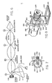
- Fig. 1 is a perspective view of a representative vibratory device for powering a work tool assembly (not shown) to be attached thereto;
- Fig. 2 is a longitudinal side elevational view, partly in section, of the vibratory device of Fig. 1;
- Fig. 3 is a perspective view of an embodiment of the vibratory endodontic device of the invention;
- Fig. 4 is view of the work tool assembly of the device of Fig. 3 partially in section, taken along line 3-3 in Fig. 3, the vibratory device and the endodontic file being abbreviated to conserve space;
- Fig. 5 is a cross-sectional view along line 5-5 of Fig. 4 illustrating the offset location of the stop means;
- Fig. 6 is a schematic diagram of the vibrational characteristics of a device according to the present invention, particularly illustrating the simultaneous vertical and horizontal components of vibratory motion of the endodontic file;
- Fig. 7 is a cross-sectional view of another embodiment of the stop means holding and adjusting mechanism of the present invention;
- Fig. 8 is a perspective view of another embodiment of the stop means holding and adjusting mechanism of the present invention;
- Fig. 9 is a perspective view of another embodiment of the stop means holding and adjusting mechanism of the present invention;
- Fig. 10 is a perspective view of another embodiment of the stop means holding and adjusting mechanism of the present invention;
- Fig. 11 is a cross-sectional view of another embodiment of the stop means holding and adjusting mechanism of the present invention;
- Fig. 12 is a cross-sectional view of another embodiment of the stop means holding and adjusting mechanism of the present invention;
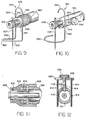
- Fig. 13 is an enlarged side view, partially in section, of another embodiment of a work tool assembly of the present invention, shown incorporating fluid transport means;
- Fig. 14 is a perspective view of another embodiment of the file and stop means holding and adjusting mechanism of the present invention;
- Fig. 15 is a cross-sectional view of the embodiment of the file and stop means holding and adjusting mechanism of the present invention, taken along line 15-15 in Fig. 14;
- Fig. 16 is a cross-sectional view of the embodiment of the file and,stop means holding and adjusting mechanism of the present invention, taken along line 16-16 in Fig. 15;
- Fig. 17 is an exploded view of another embodiment of the stop member and endodontic tool holding and adjusting means of the present invention;
- Fig. 18 is a top view of the embodiment of Fig. 17, shown assembled together;
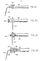
- Fig. 19 is a side elevational view of another embodiment of the endodontic tool holding means of the present invention;
- Fig. 20 is a side elevational view of another embodiment of the endodontic tool holding means of the present invention;
- Fig. 21 is a side elevational view of another embodiment of the endodontic tool holding means of the present invention; and
- Fig. 22 is a side elevational view, partly in section, of another embodiment of the endodontic tool holding means of the present invention.
- With reference to the drawings, the
vibratory device 10 comprises a housing having ahandle 12 which includes abarrel 14 and aneck 16. Attached to thedistal end 18 of thevibrator 10 is atip holder 20.Tip holder 20 is adapted to receive the shank of a work tool such as an endodontic file, as will be described more fully hereinafter. As shown in detail in the cross-sectional view of Fig. 2,handle 12 provides an elongated casing within which is mounted support means comprising a first orfront support 30 including a pair of 0-rings 31. A .second or rear resilient support is provided by acylindrical tube 32 of resilient material which is sleevably engaged about aboss portion 34 secured to a rigidrear support 36.Boss portion 34 has retaininggrooves 38 circumferentially disposed thereon for retaining resilientrear support 32 by means of retainingring 40. Disposed substantially coaxially with respect toelongated handle 12 is a vibratable, substantially rigid,hollow shaft 42.Tip holder 20 is threadedly connected to thedistal end 44 ofhollow shaft 42 via an internally threadedshaft extension 43. The proximal end ofshaft 42 is formed with retaininggrooves 48 for engaging resilientrear support 32 therein. Apin 73 is provided onshaft 42 for engaging awall 75 of a slot inrear support 36 to oppose twisting forces applied toshaft 42 during engagement or disengagement oftip holder 20 with or from the distal end ofshaft 42.Rear support 32 is retained within retaininggrooves 48 onshaft 42 by means of aretaining ring 50. - As seen most clearly in Fig. 2,
shaft 42 is formed with anintermediate section 51 having a diameter greater than the diameter of those portions ofshaft 42adjacent section 51.Outlet ports 70 are formed in the wall ofshaft 42 in theintermediate section 51 and serve to provide fluid communication for fluid media means from the inside oftubular shaft 42 to the spaceadjacent side wall 64 ofshaft 42. Centrally and axially disposed aboveintermediate portion 51 ofshaft 42 is rotor means 60, which defines agap 62 between itsinner surface 61 andside wall 64 ofshaft 42 into which fluid media is directed fromoutlet ports 70. - With reference to Figs. 1 and 2, a fluid medium, such as compressed air, is supplied from a source (not shown) through a
supply tube 74 which passes through an axially disposed opening 81 inend cap 82. The connection to the source may be made by a swivelable, quick connect coupling. The flow of compressed air passes intoplenum 76 in throughpassageway 72 andshaft 42 to fluidmedia outlet ports 70. The flow of compressed air which exhausts throughoutlet ports 70 strikes theinner wall 61 ofrotor 60 and urgesrotor 60 to rotate aboutshaft 42. Each of theoutlet ports 70 has an axis which is offset or spaced at a distance from the longitudinal axis ofshaft 42. In that configuration no port axis intersects the longitudinal axis ofshaft 42 and each ofports 70 directs a jet of air at a glancing angle with respect to theinner wall 61 ofrotor 60 so as to impart rotational movement to rotor. 60. The air passes through the end sections ofgap 62 into the main barrel section and subsequently passes through muffler means 80 which are supported on rigidrear support 36 to exhaust throughoutlet ports 56. - Stop means 78 are disposed in indented sections or
grooves 79 inouter surface 64 ofshaft 42. Typically, stop means 78 comprise O-rings sleevably engaged aboutshaft 42. Stop means 78 prevent excessive travel ofrotor 60 so thatrotor 60 is at least partially disposed about outlet means 70 at all times, including the time prior to activation of the instrument with compressed air. Thus, when air is supplied to the instrument, the air flowing throughoutlet ports 70 will contact at least a portion ofrotor 60 and initiate its rotational movement aboutshaft 42. Innormal operation rotor 60 will not contact stop means 78. A more detailed description of the manner in which the spinningrotor 60 imparts vibrational movement toshaft 42 and other aspects of the vibrator may be found in the U.S. Patents Re. 29,687 and No. 4,330,282, the disclosures of which are incorporated herein by reference. - The vibrator can include means for transporting water or other fluids (e.g. medicated irrigants) from an external source to a work tool at its operative end. The fluid supply can be continuous or controllable at the option of the operator and the source does not form a part of the present invention. A first
fluid transport hose 100 located at the rearward or proximal end ofvibrator 10 is mounted in adetachable coupling 101. Firstfluid hose 100 is connected to an external source of fluid (not shown), the forward end of the hose being connected to one end of arigid tube 103 which passes through a passageway insupport body 102.Tube 103 is disposed substantially coaxially with respect tohollow shaft 42.Fluid transport tube 103 extends throughhollow shaft 42 toward the distal end ofscaler 10 and terminates distally fromfluid seal assembly 110.Tube 103 is covered with an elastomeric tube covering 104 to dampen vibration build-up withintube 103. The forward ordistal end 106 offluid tube 103 extends intoplenum 108. -
Fluid tube end 106 is supportably received within afluid seal assembly 110 located at the forward or distal end ofvibrator 10.Fluid seal assembly 110 comprises acylindrical body 112 having apassageway 114 coaxially disposed with respect to the axis ofbody 112. Running circumferentially about the outer side wall ofcylindrical body 112 are a pair of spacedannular grooves 116, one adjacent each endcylindrical body 112. Disposed within each ofgrooves 116 is an O-ring 118 fabricated of a resilient material. O-rings 118 serve to positioncylindrical body 112 within the forward end ofhollow shaft 42 by frictional engagement of 0-rings 118 with portions ofinner wall 120 ofshaft 42. Within a midportion ofcylindrical body 112 is a chamber formed by anannular groove 122 running circumferentially along a portion ofinner wall 124 ofbody 112 betweengrooves 116. Contained withingroove 122 is an O-ring 126 which is in frictional engagement with the walls ofgroove 122 and with a portion offluid tube 106. O-ring 126 helps to properly positiontube 104 centrally withinhollow shaft 42. Positioning of the center of gravity offluid seal assembly 110 slightly forwardly offirst support 30, i.e., toward the distal end ofscaler 10, imparts a force oncylindrical body 112 tending to move it in a forward axial direction toward the distal end ofscaler 10, thereby ensuring continuous contact betweencylindrical body 112 andshoulder 132 ofshaft 42. A more detailed description of the manner in which sealing between thewater assembly 110 andshaft 42 is effected is provided , in U.S. Patent No. 4,260,380, the disclosure of which is incorporated herein by reference. - In a preferred embodiment of the invention, the
tip holder 20 of thevibratory device 10 is replaced by an assembly having a vibration-isolatedextension 201 and avibratable mandrel 202 for supporting anendodontic file 207. This embodiment is illustrated in Figs. 3, 4 and 5. An end 210 ofextension 201 is retained on thevibrator 10 by means of alocking ring 300 having an internally threadedportion 302 which is received on an externally threadedportion 304 of thedistal end 18 ofhandle 12. Depending on the vibrator to which the attachment assembly is connected, a spacer element 306 can be disposed betweenhandle 12 andextension 201 to adjust the position of the depth stop 216 with respect to thefile 207. The other end ofextension 201 is formed as a threadedend 211 adapted to engage aretaining ring 213 which is internally threaded.Extension 201 is formed with anupper slot 308 and alower hole 218 to receive an adjustable stop 214 (or depth stop). Stop 214 is formed with anupper leg 215 and a dependingstop surface 216 from the lower end of theleg 215. A cushionedportion 310 can be provided onstop surface 216, for example by surrounding the stop surface with a resilient material such as a rubber or plastic tube or by dippingstop surface 216 in a resilient material that will adhere to it, to cushion the impact between the depth stop and a tooth.Leg 215 is adapted to pass throughopenings ring 213 is threaded forwardly towardstop 214 such that it forcesleg 215 forwardly until it is fixedly retained inopenings slot 308 andhole 218 are offset from the central longitudinal axis of the vibrator so as not to interfere withmandrel 202. -
Mandrel 202 is formed with a threadedend 203 which is adapted to be received by threadedextension 43 ofhollow shaft 42. The other end ofmandrel 202 extends from the forward end ofextension 201 and is also formed with a threadedend 204. Avertical bore 206 is formed inmandrel 202 and is adapted to receive anendodontic file 207. Typically, file 207 is formed with anenlarged head 208 to prevent it from slipping downwardly throughbore 206. A threadednut 205 is provided on the threadedend 204 ofmandrel 202 to firmlysecure file 207 withinbore 206. Acollar 209 is optionally provided betweenfile 207 and the end ofextension 201 in order to lessen the possibility of shearingfile 207 whennut 205 is tightened. - In a preferred embodiment of the invention, as illustrated in the schematic drawing of Fig. 6, threaded
nut 205 is selected to have a optimal weight, depending on the size of thevibrator 10 andmandrel 202.Nut 205 is preferrably disposed to define a node (A) of the vibrational system formed byvibrator 10,mandrel 202 and file 207 depending upon the nut's weight, and, therefore acts as a seismic mass. Thebore 206, and therefore file 207, are disposed between nodes of the vibrational system, causing a working end 312 offile 207 to move in an eliptical or circular path in which the elipse or circle is disposed at an angle to the longitudinal axis of the vibrator, giving working end 312 an up-and-down motion (proportional to the amplitude of the vibration at that off-tuned point of attachment) simultaneous with the circular or eliptical motion. Both the circular or eliptical motion and the up-and-down motion have been individually found to be very efficient to enlarge root canals and the like in teeth. The simultaneous combination of these horizontal and vertical motion components, as caused by the preferred tuning and structure of the device of the present invention, gives rise to an optimal mechanical advantage for endodontic procedures. - As can be seen from the structure previously described (See Figs. 2 and 4), the
stop member 214 is isolated from the vibrational transfer fromhollow shaft 42 since it is suspended fromhousing 12, and not mandrel 202 which is directly connected to the vibrating member. Sincehollow shaft 42 is resiliently supported withinhousing 12 bysupports hollow shaft 42 andhousing 12. The use of optional cushionedportion 310 further prevents the transfer of vibration between a tooth being operated on and stopmember 214.Stop member 214 is thereby effectively isolated from the vibrational transfer, making accurate depth placement of the end offile 207 is possible. Furthermore, because minimal vibrations are transferred to stopmember 214, the failure life ofstop member 214 is accordingly extended. -
Stop member 214 is advantageously formed from a square wire or a rectangular wire such that it can be automatically oriented with respect to thefile 207 in the proper position by placement in a rectangular or square-shaped opening such as 218 and 308 . It then is only necessary that thestop member 214 be moved vertically up or down to position it with respect to the end offile 207 for proper placement. Stopsurface 216 is conveniently placed such that it circumscribes at least a portion offile 207 but does not touch the file during any of the vibratory motion imparted thereto. In that configuration, stopsurface 216 is positioned to contact the tooth surface during use without regard to the particular orientation'of thevibratory device 10 when thefile 207 is located within the tooth during use. - In many instances it is desirable to provide a fluid, often containing a medicament, to the working end of
file 207. Such can be accomplished by utilizing the vibrator described in Fig. 2 and the work tool assemby, particularly as illustrated in Fig. 4. As shown in Fig. 4, themandrel 202 is formed with alongitudinal bore 220 into which is inserted atube 221. Adistal end 314 oftube 221 conveniently extends a short distance out from anopening 316 in adistal end member 318 ofmandrel 202, and fluid flow can be directed directly on to file 207 or on to a tooth being operated on. Aproximal end 320 oftube 221 is in fluid communication withplenum 108 to receive and transport fluid from the vibratory device. - Various alternative embodiments for attaching the
file 207 and stopmember 214 to themandrel 202 are illustrated in Figs. 7 - 22. For example, an internal stop member holding embodiment is illustrated in Fig. 7, where astop member 214 is shown disposed throughopenings Stop member 214 has anenlarged portion 330 to prevent it from accidentally falling through the openings. A threadedmember 332 slidingly extends through a side ofextension 201, past the point through which the stop member passes, and is connected to ablock 334. A reciprocally threadedmember 336, which also has anenlarged end 338, is disposed on threadedmember 332. By tightening the reciprocally threadedmember 336, the threadedmember 332 is urged towards the side wall ofextension 201, thereby tighteningblock 334 against theupper leg 215 ofstop member 214 and holding it in place. In another embodiment of the internal stop member holding concept (not shown) a conduit can be disposed betweenopenings - Turning to Fig. 8, a side slot with stop holding means embodiment is shown having a
vertical slot 340 disposed in the side wall ofextension 201, and having an uppercross-sectional portion 342 ofextension 201 and a lowercross-sectional portion 344. A stop member 346, having anupper leg 348, optionally withserrations 350 disposed into one side of it, and optionally with anenlarged portion 352 on its top, and also having alower leg 354 with a cushionedportion 356 encircling a file, is disposed in the slot. A stop member retaining means, such as aslidable sleeve 358 is disposed aboutextension 201 and has two recessedportions central tab 364 between them.Tab 364 can also have urging means 366, such as a spring loaded ball bearing, disposed on the inside thereof.Upper leg 348 optionally has a series ofmarkings 368 on its side oppositeserrations 350, so that by placing stop member 346 insideslot 340 and aligning the marking 368 with a portion of thecentral tab 364 the depth of the stop member can be selectively set and held in place by the reciprocal action of theserrations 350 receiving thecross-sections sleeve 358 is slid forward, where together with urging means 366, it holds the stop member in place. Additional retention members (such as a series of internally disposed bearings on the sleeve and a receiving groove disposed in the housing - not shown) may be associated with the sleeve in order to hold it in its closed position with respect to the stop member. Readjustment of the stop member is very easy using the invention according to this embodiment. - Turning to Fig. 9, the
extension 201 is provided with a pair ofslots 340 into which a spring cliptype stop member 370 is disposed.Stop member 370 has a pair ofupper legs top portion 376, and a pair oflower legs rounded portion 382. A threadedsleeve 384 is disposed aroundextension 201 such that by turning the sleeve, it will be urged againstupper legs top portion 376 is particularly advantageous in that it is unlikely to pierce a rubber dam. Thestop member 370 is attached by being yieldingly slid over the top ofextension 201 into the slots 340. Alternatively, as shown in Fig. 9, thesupport legs serrations 375 which will be urged against the cross-section ofhousing 201 formed by the upper and lower ends ofslots 340, thereby holdingstop member 370 in place without additional retaining means such assleeve 384. - In Fig. 10 an adjustable side pressure stop member retaining embodiment is illustrated, wherein a
stop member 386, similar to stopmember 370 is shown as having a singleupper leg 388 and alower leg 390 looping aroung afile 207.Upper leg 388 is received in aslot 340, and has a curvedupper portion 392 to avoid piercing a rubber dam. A side-mountedholding member 394 is movable againstupper leg 388 ofstop member 386 by atightenable member 396 which is received in a side ofextension 201. - Referring to Fig. 11, a
stop member 398 is shown held in place in a slot or a hole by a spring-loadedmember 400.Member 400 has ashoulder 402 designed to surround thestop member 398. The forward urging of aspring 404 maintains themember 400 against thestop 398 when asleeve 406 is slid back, thereby permitting height adjustment of thestop member 398 and at the same time preventing it from dislodging from the instrument.Member 400 must be moved back, against the force of thespring 404 in order to remove the stop member completely. The stop member can be locked in place by sliding thesleeve 406 forward. - Turning to Fig. 12, a screw thread mounted adjustable stop member is shown, wherein a
stop member 410 having a pair ofupper legs 412 and 414 disposed through a pair of receiving openings orslots extension 201 has anupper cross member 420 with a threadedopening 422 therethrough. A reciprocally threadedelongated member 424, such as a bolt, is turnably held in atop portion 426 ofextension 201 and received in theopening 422. Aknob 428 is fixedly attached to the top ofelongated member 424 for turning it and thereby raising or loweringstop member 410. - As illustrated in the alternate embodiment of Fig. 13, the head portion of
mandrel 202 can be formed withvertical bores file 207 and stopmember 214, respectively. Anend cap 223 having holes to accommodate the ends offile 207 and stop 214 is placed about the head ofmandrel 202 and can be conveniently spring loaded withspring 224 to retainfile 207 and stopmember 214 in selected positions. It will be apparent that a longitudinal bore such asbore 220 and a conduit such astube 221 can be suitably placed withinmandrel 202 which is illustrated in Fig. 4. Such an irrigation feature is considered to be within the presently preferred embodiments. - As shown in Figs. 14, 15 and 16, the
mandrel 202 can be formed with a substantiallycylindrical mandrel head 225 having avertical bore 226 and avertical bore 227 adapted to receivefile 207 and stopmember 214, respectively.Mandrel 202 can be provided with alongitudinal bore 228 which intersects bore 226 and provides a flow channel for transporting fluid to the end offile 207.File 207 and stopmember 214 are fixedly retained inhead 225 by means of a retainingtube 229 which is formed with top and bottom holes, designated as 235 and 234, respectively, to receive the upper ends offile 207 and stopmember 214. The inner diameter of retainingtube 229 is made somewhat larger than the outer diameter ofhead 225 ofmandrel 202.Mandrel 202 is provided with atransverse bore 230 which is internally threaded and adapted to receive ascrew 232 which enters retainingtube 229 through ahorizontal hole 231 formed in one side thereof. Conveniently athumb wheel 233 is connected to screw 232 to assist the operator in its inward and outward movement. As can be seen most clearly in Fig. 16, tightening ofscrew 232moves retaining tube 229 to a position which forces file 207 and stopmember 214 against the walls of their respective receiving bores inhead 225 ofmandrel 202. That force effectively maintains file 207 and stopmember 214 in fixed positions during use. - In still another embodiment, as can be seen in Figs. 17 and 18,
mandrel 202 is formed with a substantiallyrectangular head 236 havingtransverse bores vertical grooves Vertical grooves file 207 and stopmember 214, respectively, as can be seen most clearly in Fig. 18. A locatingpin 241 is conveniently fixed tohead 236. A retainingplate 242 is provided opposite the grooved face ofhead 236, and retainingplate 242 is formed with abore 243 and ahole 244.Bore 243 is adapted to receive abolt 247 and is aligned withbore 237 inhead 236.Bore 244 is adapted to receive locatingpin 241 and the interaction ofpin 241 with retainingplate 242 serves to prevent twisting of retainingplate 242 when thehead 236 and retainingplate 242 are fastened together.Vertical grooves plate 242 and are adapted to receivefile 207 and stopmember 214, respectively, as can again be seen most clearly in Fig. 18. A substantially cylindrical groove extending vertically along the other face of retainingplate 242 is provided andgroove 251 is dimensioned to mate withcurved surface 249 formed onbolt 247. Retainingplate 242 andhead 236 are secured by the engagement ofbolt 247 on its threadedend 248 and a threadednut 250.Bolt 247 extends throughbores bore 254 innut 250. Aspring 252 is provided inbore 238 to loadstop member 214 and minimize the vibration transmitted to stopmember 214 during use of the instrument. Awasher 253, as seen most clearly in Fig. 18, can be interposed betweennut 250 and the end ofspring 252 to effectively retainspring 252 withinbore 238. - As shown in Fig. 19,
mandrel 202 is provided with asplit end 255 having a threaded bore and ascrew 256 inserted therein.File 207 is inserted within the legs formed insplit end 255 and can be retained therein by the pressure ofscrew 256. In Fig. 20,mandrel 202 is provided with an internally threaded bore 257 in which is inserted a threadedscrew 258 which bears againstfile 207 to retain it thereon. In Fig. 21, themandrel 202 is formed with a threadedend 260 having a bore there through to receivefile 207. A captured, threadednut 261 is positioned betweenfile 207 and the vibratory portion of the device and can be tightened to press file 207 toward the forward end ofend 260 to retain it thereon. In Fig. 22,mandrel 202 is provided with atapered bore 262 into which is inserted acollet 263 having split, tapered ends. Anut 264 having an internaltapered surface 265 is threadely received on the threaded end ofmandrel 202.File 207 is received incollet 263 and whennut 264 is tightened, the tapered ends ofcollet 263 interact with the corresponding tapered surfaces ofnut 264 and bore 262 to firmly gripfile 207 and hold it in place. - While this invention has been described with reference to specific embodiments thereof, it should be understood by those skilled in this art that various changes may be made and an equivalents may be substituted without departing from the true spirit and scope of the invention. For example, the stop member of the invention can be used with mechanically driven devices which oscillate the file in a rotary or linear fashion. It can also be used with other dental instruments such as drills and manual files, or with other surgical instruments such as bone cutting and drilling instruments used in orthopedic, neurological and similar procedures. It is, however, particularly suited for use within the limited space of the mouth. In addition, the various novel elements, as described herein can be used individually or collectively, as desired. All such modifications are intended to be within the scope of the Claims appended hereto.
Claims (25)
Applications Claiming Priority (4)
| Application Number | Priority Date | Filing Date | Title |
|---|---|---|---|
| US06/433,075 US4484891A (en) | 1982-10-06 | 1982-10-06 | Vibratory endodontic device |
| US433075 | 1982-10-06 | ||
| US06/523,833 US4571183A (en) | 1982-10-06 | 1983-08-18 | Vibratory endodontic device |
| US523833 | 1983-08-18 |
Publications (3)
| Publication Number | Publication Date |
|---|---|
| EP0106632A2 true EP0106632A2 (en) | 1984-04-25 |
| EP0106632A3 EP0106632A3 (en) | 1984-07-11 |
| EP0106632B1 EP0106632B1 (en) | 1989-01-25 |
Family
ID=27029741
Family Applications (1)
| Application Number | Title | Priority Date | Filing Date |
|---|---|---|---|
| EP83306043A Expired EP0106632B1 (en) | 1982-10-06 | 1983-10-05 | Vibratory device, dental or surgical instrument, and depth stop and attachment assembly therefor |
Country Status (3)
| Country | Link |
|---|---|
| US (1) | US4571183A (en) |
| EP (1) | EP0106632B1 (en) |
| CA (1) | CA1231261A (en) |
Cited By (11)
| Publication number | Priority date | Publication date | Assignee | Title |
|---|---|---|---|---|
| EP0139960A1 (en) * | 1983-09-30 | 1985-05-08 | Dentsply International, Inc. | Endodontic unit |
| WO1986005967A1 (en) * | 1985-04-15 | 1986-10-23 | Sven Karl Lennart Goof | Tool, in particular for use in cleansing tooth root canals, and drive instrument for such tool |
| FR2599241A2 (en) * | 1982-11-03 | 1987-12-04 | Micro Mega Sa | Device for holding a boring tool in a vibrationally moving dental instrument |
| FR2623998A1 (en) * | 1987-12-02 | 1989-06-09 | Micro Mega Sa | Device for holding a tool for drilling dental root canals |
| DE3911853A1 (en) * | 1989-04-11 | 1990-10-25 | Aesculap Ag | MEDICAL HANDPIECE |
| WO1998031295A1 (en) * | 1997-01-14 | 1998-07-23 | Kaltenbach & Voigt Gmbh & Co. | Medical or dental handpiece for treating by chip-removal or abrasion preferably tissue from the human or animal body |
| GB2302285B (en) * | 1995-06-16 | 1998-12-09 | Zeev Ram | Dental apparatus including multiple-use electrically-oscillated handpiece |
| EP0962192A1 (en) * | 1998-06-05 | 1999-12-08 | Kaltenbach & Voigt Gmbh & Co. | Medical or dental instrument for cutting body tissue and tool therefore |
| EP1175873A1 (en) * | 2000-07-24 | 2002-01-30 | Mani, Inc. | Dental handpiece with tool positioning means |
| US9668807B2 (en) | 2012-05-01 | 2017-06-06 | Covidien Lp | Simplified spring load mechanism for delivering shaft force of a surgical instrument |
| US11173013B2 (en) * | 2019-10-18 | 2021-11-16 | Joshua Maxwell | Dental system with hand piece for endodontic files |
Families Citing this family (30)
| Publication number | Priority date | Publication date | Assignee | Title |
|---|---|---|---|---|
| JPS62201151A (en) * | 1986-03-03 | 1987-09-04 | 株式会社中西歯科器械製作所 | Guide apparatus for dental treatment tool |
| CH671684A5 (en) * | 1986-06-02 | 1989-09-29 | Micro Mega Sa | |
| US4818229A (en) * | 1987-04-29 | 1989-04-04 | Engler Engineering Corporation | Dental ultrasonic endodontic unit |
| AT388283B (en) * | 1987-08-24 | 1989-05-26 | Buermoos Dentalwerk | DENTAL HANDPIECE |
| US6045362A (en) * | 1995-06-06 | 2000-04-04 | Ultradent Products, Inc. | Endodontic methods for progressively, sectionally and anatomically preparing root canals with specific instruments for each section having predetermined working lengths |
| US6585513B2 (en) | 1995-06-06 | 2003-07-01 | Ultradent Products, Inc. | Endodontic systems and methods for preparing apical portions of root canals with a set of files having large tapers |
| US6379155B1 (en) | 1996-06-06 | 2002-04-30 | Ultradent Products, Inc. | Endodontic systems and methods for the anatomical, sectional and progressive corono-apical preparation of root canals with instruments utilizing stops |
| IT1278092B1 (en) * | 1995-06-06 | 1997-11-17 | Francesco Riitano | ENDODONTIC INSTRUMENT FOR RAPID MECHANICAL ENLARGEMENT OF THE CANAL ENTRY AND TARGETED RECTIFICATION OF THE FIRST TWO THIRD THIRD PARTIES. |
| US6059572A (en) * | 1995-06-06 | 2000-05-09 | Ultradent Products, Inc. | Endodontic methods for the anatomical, sectional and progressive corono-apical preparation of root canals with three sets of dedicated instruments |
| US6558163B2 (en) | 1995-06-06 | 2003-05-06 | Ultradent Products, Inc. | Endodontic systems and methods for preparing upper portions of root canals with increasingly rigid files |
| US6042375A (en) * | 1995-06-06 | 2000-03-28 | Ultradent Products, Inc. | Endodontic systems for progressively, sectionally and anatomically preparing root canals with specific instruments for each section having predetermined working lengths |
| US6390819B2 (en) | 1995-06-06 | 2002-05-21 | Ultradent Products, Inc. | Endodontic systems and methods for the anatomical, sectional and progressive corono-apical preparation of root canals with dedicated stainless steel instruments and dedicated nickel/titanium instruments |
| DE19751682A1 (en) * | 1997-11-21 | 1999-06-17 | Kaltenbach & Voigt | Medical or dental medical treatment instrument for in particular machining treatment of body tissue or a substitute and tool for such a treatment instrument |
| DE19916114A1 (en) * | 1999-04-09 | 2000-10-12 | Kaltenbach & Voigt | Adjustment gauge for bit stop of dental or medical hand piece; has connection element to position it on hand piece with scale that extends parallel to bit stop and adjustment path of bit stop |
| DE60032144T2 (en) | 1999-07-13 | 2007-04-12 | Dentsply International Inc. | ROTATING HANDPIECE FOR AN ENDODONTIC INSTRUMENT |
| US6390814B1 (en) | 1999-08-18 | 2002-05-21 | Vernon Gardiner | Endodontic appliance which stops instruments from extending too far into a root canal during treatment |
| DE10039198B4 (en) * | 2000-08-10 | 2015-03-19 | Kaltenbach & Voigt Gmbh | Medical or dental treatment instrument with a particular pneumatic vibration drive |
| FR2831050A1 (en) * | 2001-10-19 | 2003-04-25 | Anthogyr Sa | Dental hand piece with adjustable depth stop for drilling comprises several conduits leading fluid from external conduits to tool working zone, axial locking of stop comprising guillotine |
| US6926526B2 (en) * | 2002-05-24 | 2005-08-09 | Kenneth G. Hudak | Endodontic adapter for a sonic scaler |
| US7008223B2 (en) * | 2003-11-19 | 2006-03-07 | Essential Dental Systems, Inc. | Endodontic instrument for accessing a pulp chamber |
| IL160335A0 (en) * | 2004-02-11 | 2004-07-25 | Medic Nrg Ltd | Assemblies and methods for measuring tooth apex location |
| US7156189B1 (en) * | 2004-12-01 | 2007-01-02 | The United States Of America As Represented By The Administrator Of The National Aeronautics And Space Administration | Self mountable and extractable ultrasonic/sonic anchor |
| US8043088B2 (en) | 2005-05-16 | 2011-10-25 | Johnson Douglas B | Endodontic procedure employing simultaneous liquefaction and acoustic debridgement |
| US7695280B1 (en) * | 2005-12-16 | 2010-04-13 | Yazigi Ernest M | Dental implant and drill for forming socket for the same |
| FR2906707B1 (en) * | 2006-10-06 | 2009-11-06 | Anthogyr Soc Par Actions Simpl | DENTAL HAND PIECE WITH STOP DEVICE |
| US20120255558A1 (en) * | 2011-04-05 | 2012-10-11 | Jose Luis Alvarez | Tissue guard for medical applications |
| FR2993168B1 (en) * | 2012-07-16 | 2014-08-22 | Satelec Soc | ULTRASONIC SURGICAL MICROMOTOR |
| US9839492B2 (en) * | 2013-09-05 | 2017-12-12 | Heriberto Bujanda Wong | Ultrasonic ring tip to activate endodontic instruments |
| US10595962B2 (en) * | 2017-04-04 | 2020-03-24 | Han Instruments, LLC | Ultrasonic endodontic surgical instrument |
| WO2020007865A1 (en) * | 2018-07-03 | 2020-01-09 | Woodwelding Ag | Device for perforating a dense bone layer |
Citations (6)
| Publication number | Priority date | Publication date | Assignee | Title |
|---|---|---|---|---|
| GB830142A (en) * | 1955-03-08 | 1960-03-09 | Cavitron Corp | Sonic and ultrasonic cutting tools |
| FR1325071A (en) * | 1962-03-16 | 1963-04-26 | Dental instrument, in particular, for reaming root canals | |
| US4217098A (en) * | 1974-07-30 | 1980-08-12 | Micro-Mega S.A. | Device for limiting the penetration of dental root canal instruments |
| EP0015672A1 (en) * | 1979-02-16 | 1980-09-17 | Syntex (U.S.A.) Inc. | Vibratory device, work tool assembly, and dental scaler incorporating them |
| US4229168A (en) * | 1978-08-23 | 1980-10-21 | Scholz Jr Howard W | Contra-angle ultrasonic endodontic instrument |
| DE3105424A1 (en) * | 1980-06-30 | 1982-01-21 | Howard Dr. 20910 Silver Spring Martin, Md. | HOLDING DEVICE FOR INSTRUMENTS, ESPECIALLY ENDODONTIC ULTRASONIC INSTRUMENTS |
Family Cites Families (27)
| Publication number | Priority date | Publication date | Assignee | Title |
|---|---|---|---|---|
| US349338A (en) * | 1886-09-21 | Dental tool | ||
| US29687A (en) * | 1860-08-21 | Stove | ||
| US3124878A (en) * | 1964-03-17 | Sonic dental tool | ||
| US1046560A (en) * | 1912-01-30 | 1912-12-10 | David E Coulson | Dental instrument. |
| US1821079A (en) * | 1929-07-20 | 1931-09-01 | Charles E Schultze | Dental instrument |
| US2485900A (en) * | 1947-07-02 | 1949-10-25 | Elmer L Mckeen | Guard attachment for dental tools |
| DE808873C (en) * | 1948-10-02 | 1951-07-19 | Max Nirschl | Separating handpiece with drive and clamping device for saws and sanding sheets suitable for separating teeth |
| US2690617A (en) * | 1951-09-15 | 1954-10-05 | James B Giern | Needle holding dental tool |
| DE1084870B (en) * | 1958-01-09 | 1960-07-07 | Dr Reinmar Binder | Device for the mechanical preparation of the root canals of teeth |
| US3037282A (en) * | 1958-11-21 | 1962-06-05 | Aktarian Sarkis | Adjustable twin dental handpiece |
| US3058218A (en) * | 1959-05-07 | 1962-10-16 | Cavitron Ultrasonics Inc | Methods and means for driving small diameter shafts at high rotational speeds |
| FR1397366A (en) * | 1968-05-06 | 1965-04-30 | Micro Mega Sa | Method for driving dental tools with canals and contra-angle dentistry for the implementation of this method |
| US3518766A (en) * | 1969-01-30 | 1970-07-07 | Emanuel Burt | Piezoelectric cleaning device with removable workpiece |
| DK125820B (en) * | 1971-03-31 | 1973-05-07 | S Goof | Material processing apparatus with electromagnetically moving working means. |
| CH543879A (en) * | 1971-11-12 | 1973-11-15 | Dent Jelicic Dusan Dr Med | Dental drill handpiece |
| US3892040A (en) * | 1973-03-26 | 1975-07-01 | John C Marquis | Toothpick holder |
| IT985533B (en) * | 1973-06-27 | 1974-12-10 | Cir Srl | ENDODONTIC INSTRUMENT FOR IRRIGATION OF DENAL ROOT CANALS AND THE CONTEMPORARY ASPIRATION OF WASTE LIQUID FROM THESE CHANNELS |
| CH573745A5 (en) * | 1973-11-08 | 1976-03-31 | Riitano Francesco | |
| US4019254A (en) * | 1975-06-30 | 1977-04-26 | Oscar Malmin | Endodontic operating instrument |
| US4028810A (en) * | 1975-08-11 | 1977-06-14 | Karl F. Kinkel | Root canal file |
| CH602086A5 (en) * | 1976-04-27 | 1978-07-31 | Freudiger Beat Urs | Dental drill gum protector |
| DE2733641A1 (en) * | 1977-06-13 | 1978-12-21 | Crea Sa | MEASURING ELECTRODE FOR DETERMINING THE DEGREE OF CONCENTRATION OF CONCENTRATED SULFUR ACID SOLUTIONS AND THE PROCESS FOR THEIR PRODUCTION AND USE |
| US4165562A (en) * | 1977-08-12 | 1979-08-28 | Sarfatti David E | Precision endodontic file |
| US4182040A (en) * | 1978-02-21 | 1980-01-08 | Bechtold Edmund C Jr | Endodontic file holder and gauge |
| US4295827A (en) * | 1979-12-31 | 1981-10-20 | Howard Martin | Endodontic flow through ultrasonic instrument holder attachment |
| DE3010636A1 (en) * | 1980-03-20 | 1981-10-01 | MEDTRONIC medizinisch-elektronische Gerätegesellschaft mbH, 6390 Usingen | Tool attachment for ultrasonic dental appts. - has hollow cylinder enclosing tool working surface inserted in tool handgrip |
| US4484891A (en) * | 1982-10-06 | 1984-11-27 | Syntex (U.S.A.) Inc. | Vibratory endodontic device |
-
1983
- 1983-08-18 US US06/523,833 patent/US4571183A/en not_active Expired - Fee Related
- 1983-10-05 EP EP83306043A patent/EP0106632B1/en not_active Expired
- 1983-10-05 CA CA000438394A patent/CA1231261A/en not_active Expired
Patent Citations (6)
| Publication number | Priority date | Publication date | Assignee | Title |
|---|---|---|---|---|
| GB830142A (en) * | 1955-03-08 | 1960-03-09 | Cavitron Corp | Sonic and ultrasonic cutting tools |
| FR1325071A (en) * | 1962-03-16 | 1963-04-26 | Dental instrument, in particular, for reaming root canals | |
| US4217098A (en) * | 1974-07-30 | 1980-08-12 | Micro-Mega S.A. | Device for limiting the penetration of dental root canal instruments |
| US4229168A (en) * | 1978-08-23 | 1980-10-21 | Scholz Jr Howard W | Contra-angle ultrasonic endodontic instrument |
| EP0015672A1 (en) * | 1979-02-16 | 1980-09-17 | Syntex (U.S.A.) Inc. | Vibratory device, work tool assembly, and dental scaler incorporating them |
| DE3105424A1 (en) * | 1980-06-30 | 1982-01-21 | Howard Dr. 20910 Silver Spring Martin, Md. | HOLDING DEVICE FOR INSTRUMENTS, ESPECIALLY ENDODONTIC ULTRASONIC INSTRUMENTS |
Cited By (12)
| Publication number | Priority date | Publication date | Assignee | Title |
|---|---|---|---|---|
| FR2599241A2 (en) * | 1982-11-03 | 1987-12-04 | Micro Mega Sa | Device for holding a boring tool in a vibrationally moving dental instrument |
| EP0139960A1 (en) * | 1983-09-30 | 1985-05-08 | Dentsply International, Inc. | Endodontic unit |
| WO1986005967A1 (en) * | 1985-04-15 | 1986-10-23 | Sven Karl Lennart Goof | Tool, in particular for use in cleansing tooth root canals, and drive instrument for such tool |
| FR2623998A1 (en) * | 1987-12-02 | 1989-06-09 | Micro Mega Sa | Device for holding a tool for drilling dental root canals |
| DE3911853A1 (en) * | 1989-04-11 | 1990-10-25 | Aesculap Ag | MEDICAL HANDPIECE |
| GB2302285B (en) * | 1995-06-16 | 1998-12-09 | Zeev Ram | Dental apparatus including multiple-use electrically-oscillated handpiece |
| WO1998031295A1 (en) * | 1997-01-14 | 1998-07-23 | Kaltenbach & Voigt Gmbh & Co. | Medical or dental handpiece for treating by chip-removal or abrasion preferably tissue from the human or animal body |
| EP0962192A1 (en) * | 1998-06-05 | 1999-12-08 | Kaltenbach & Voigt Gmbh & Co. | Medical or dental instrument for cutting body tissue and tool therefore |
| US6267594B1 (en) | 1998-06-05 | 2001-07-31 | Kaltenbach & Voigt Gmbh & Co. | Medical or dental-medical instrument for material-removing working of body tissue and tool for such an instrument |
| EP1175873A1 (en) * | 2000-07-24 | 2002-01-30 | Mani, Inc. | Dental handpiece with tool positioning means |
| US9668807B2 (en) | 2012-05-01 | 2017-06-06 | Covidien Lp | Simplified spring load mechanism for delivering shaft force of a surgical instrument |
| US11173013B2 (en) * | 2019-10-18 | 2021-11-16 | Joshua Maxwell | Dental system with hand piece for endodontic files |
Also Published As
| Publication number | Publication date |
|---|---|
| US4571183A (en) | 1986-02-18 |
| CA1231261A (en) | 1988-01-12 |
| EP0106632A3 (en) | 1984-07-11 |
| EP0106632B1 (en) | 1989-01-25 |
Similar Documents
| Publication | Publication Date | Title |
|---|---|---|
| US4571183A (en) | Vibratory endodontic device | |
| US4484891A (en) | Vibratory endodontic device | |
| CA1231859A (en) | Endodontic unit | |
| CA1160080A (en) | Dental scaler having scaling tip with rounded edge work surfaces particularly suitable for circular or ellipsoidal patterns of vibration | |
| AU2004253548B2 (en) | Ultrasonic dental tool having a light source | |
| EP0217890B1 (en) | Endodontic tool for use in cleansing tooth root canals, and drive instrument for such tool | |
| US6086369A (en) | Ultrasonic dental scaler insert | |
| US4283174A (en) | Dental scaler having scaling tip particularly suitable for circular or ellipsoidal patterns of vibration | |
| CA1168071A (en) | Vibratory device having tool assembly with fluid transport means | |
| US4295827A (en) | Endodontic flow through ultrasonic instrument holder attachment | |
| EP0092861A1 (en) | Vibratory device and dental scaler incorporating it | |
| JPH09509341A (en) | Work tool exchange method in dental equipment and work tool exchanged | |
| JPS5830052B2 (en) | Myelinless dental instrument holder | |
| US4260380A (en) | Vibratory device with fluid transport means | |
| JPH0318356A (en) | Hand piece for dentistry | |
| EP0233203A4 (en) | Tool holder for ultrasonic endodontic apparatus. | |
| JP2001514923A (en) | Medical or dental instruments and tools for such instruments | |
| CA1265686A (en) | Vibratory endodontic device | |
| JP5857277B2 (en) | Dental vibratory handpiece device with endoscope probe | |
| EP0626829A1 (en) | Endodontic apparatus for retrofill cavity preparation | |
| EP0015672B1 (en) | Vibratory device, work tool assembly, and dental scaler incorporating them | |
| US20070190486A1 (en) | Dental instrument with light | |
| CA1165594A (en) | Vibratory device with fluid transport means |
Legal Events
| Date | Code | Title | Description |
|---|---|---|---|
| PUAI | Public reference made under article 153(3) epc to a published international application that has entered the european phase |
Free format text: ORIGINAL CODE: 0009012 |
|
| AK | Designated contracting states |
Designated state(s): AT BE CH DE FR GB IT LI LU NL SE |
|
| PUAL | Search report despatched |
Free format text: ORIGINAL CODE: 0009013 |
|
| AK | Designated contracting states |
Designated state(s): AT BE CH DE FR GB IT LI LU NL SE |
|
| 17P | Request for examination filed |
Effective date: 19840920 |
|
| RBV | Designated contracting states (corrected) |
Designated state(s): GB |
|
| GRAA | (expected) grant |
Free format text: ORIGINAL CODE: 0009210 |
|
| AK | Designated contracting states |
Kind code of ref document: B1 Designated state(s): GB |
|
| PGFP | Annual fee paid to national office [announced via postgrant information from national office to epo] |
Ref country code: GB Payment date: 19890930 Year of fee payment: 7 |
|
| PLBE | No opposition filed within time limit |
Free format text: ORIGINAL CODE: 0009261 |
|
| STAA | Information on the status of an ep patent application or granted ep patent |
Free format text: STATUS: NO OPPOSITION FILED WITHIN TIME LIMIT |
|
| 26N | No opposition filed | ||
| PG25 | Lapsed in a contracting state [announced via postgrant information from national office to epo] |
Ref country code: GB Effective date: 19901005 |
|
| GBPC | Gb: european patent ceased through non-payment of renewal fee |