EP0107791A1 - Method of manufacturing light wave guide branchings and multi-demultiplexers using the principle of beam splitting - Google Patents
Method of manufacturing light wave guide branchings and multi-demultiplexers using the principle of beam splitting Download PDFInfo
- Publication number
- EP0107791A1 EP0107791A1 EP83109570A EP83109570A EP0107791A1 EP 0107791 A1 EP0107791 A1 EP 0107791A1 EP 83109570 A EP83109570 A EP 83109570A EP 83109570 A EP83109570 A EP 83109570A EP 0107791 A1 EP0107791 A1 EP 0107791A1
- Authority
- EP
- European Patent Office
- Prior art keywords
- filter
- mirror
- parallel
- optical fibers
- optical
- Prior art date
- Legal status (The legal status is an assumption and is not a legal conclusion. Google has not performed a legal analysis and makes no representation as to the accuracy of the status listed.)
- Granted
Links
Images

Classifications
-
- G—PHYSICS
- G02—OPTICS
- G02B—OPTICAL ELEMENTS, SYSTEMS OR APPARATUS
- G02B6/00—Light guides; Structural details of arrangements comprising light guides and other optical elements, e.g. couplings
- G02B6/24—Coupling light guides
- G02B6/26—Optical coupling means
- G02B6/28—Optical coupling means having data bus means, i.e. plural waveguides interconnected and providing an inherently bidirectional system by mixing and splitting signals
- G02B6/293—Optical coupling means having data bus means, i.e. plural waveguides interconnected and providing an inherently bidirectional system by mixing and splitting signals with wavelength selective means
- G02B6/29379—Optical coupling means having data bus means, i.e. plural waveguides interconnected and providing an inherently bidirectional system by mixing and splitting signals with wavelength selective means characterised by the function or use of the complete device
- G02B6/2938—Optical coupling means having data bus means, i.e. plural waveguides interconnected and providing an inherently bidirectional system by mixing and splitting signals with wavelength selective means characterised by the function or use of the complete device for multiplexing or demultiplexing, i.e. combining or separating wavelengths, e.g. 1xN, NxM
-
- G—PHYSICS
- G02—OPTICS
- G02B—OPTICAL ELEMENTS, SYSTEMS OR APPARATUS
- G02B6/00—Light guides; Structural details of arrangements comprising light guides and other optical elements, e.g. couplings
- G02B6/24—Coupling light guides
- G02B6/26—Optical coupling means
- G02B6/28—Optical coupling means having data bus means, i.e. plural waveguides interconnected and providing an inherently bidirectional system by mixing and splitting signals
- G02B6/293—Optical coupling means having data bus means, i.e. plural waveguides interconnected and providing an inherently bidirectional system by mixing and splitting signals with wavelength selective means
- G02B6/29346—Optical coupling means having data bus means, i.e. plural waveguides interconnected and providing an inherently bidirectional system by mixing and splitting signals with wavelength selective means operating by wave or beam interference
- G02B6/29361—Interference filters, e.g. multilayer coatings, thin film filters, dichroic splitters or mirrors based on multilayers, WDM filters
- G02B6/29368—Light guide comprising the filter, e.g. filter deposited on a fibre end
-
- Y—GENERAL TAGGING OF NEW TECHNOLOGICAL DEVELOPMENTS; GENERAL TAGGING OF CROSS-SECTIONAL TECHNOLOGIES SPANNING OVER SEVERAL SECTIONS OF THE IPC; TECHNICAL SUBJECTS COVERED BY FORMER USPC CROSS-REFERENCE ART COLLECTIONS [XRACs] AND DIGESTS
- Y10—TECHNICAL SUBJECTS COVERED BY FORMER USPC
- Y10T—TECHNICAL SUBJECTS COVERED BY FORMER US CLASSIFICATION
- Y10T29/00—Metal working
- Y10T29/49—Method of mechanical manufacture
- Y10T29/49799—Providing transitory integral holding or handling portion
Definitions
- the present invention relates to a method for the production of optical waveguides and multi / demultiplexers according to the beam splitter principle according to the preamble of claim 1.
- the body connection step is carried out first by adjusting the body and the further body relative to one another and cementing them together. Then the process step for the production of the body is carried out with a filter or mirror, a separation at an angle of 45 ° or 70 ° to the fiber axes being carried out.
- the separating surface on the separating part which also has the optical waveguide of the further body, must be ground very carefully to such an extent that after connecting the separating parts, the light reflected by the filter or mirror from an optical waveguide of one body by the assigned optical waveguide of the further body can be detected. This step is time-consuming and critical with regard to the yield of branching elements.
- the object of the invention is therefore to improve the method of the type mentioned in that the time-consuming and critical in terms of yield There is no need to grind one parting surface.
- the adjustment effort in the body connection step can be greatly reduced if, according to claim 2, bodies are used with reference surfaces which can be placed on a stop surface in the body connection step and are parallel to the planes spanned by the paired optical waveguides. As a result, the entire adjustment can be reduced to a linear displacement in the direction of the severed optical fiber axes, which can also be controlled by means of microprocessors.
- a body is preferably produced in accordance with claim 3.
- Base bodies which are preferably used for the bodies are specified in claim 8.
- the wavelength-selective filter or the partially transparent mirror is usually applied by vapor deposition. Difficulties arise in the manufacture of branches and multi- or demultiplexers with fiber tails because the fiber tails interfere with the recipient. To avoid these difficulties, the procedure can be as set out in claim 9. Due to the double severing, a fiber-tail-free separating part with a polished separating surface to be steamed can be obtained, which can be steamed without interference in the recipient. Additional coupling losses have to be accepted with this method, but these are low.
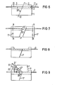
- FIGS. 6 to 9 show individual process steps of a process for producing an optical waveguide branch or multiplexer / demultiplexer with fiber tails using the example of a multiplexer / demultiplexer with a 70 "filter.
- Figures 1 and 2 show in a side or fragmentary end view the one body used in the manufacture of the branch or multi / demultiplexer with 45 ° mirror or filter.
- This has a base body, which consists of a support body 1, for example made of quartz glass, to which a silicon plate 2 is glued.
- a plurality of equidistant, V-shaped grooves 21 have been produced in the silicon wafer 2 by anisotropic etching, which grooves run parallel according to FIGS. 1 to 5 and are arranged in the flat side surface 20 of the silicon wafer facing away from the support body 1.
- Optical waveguides 4 in the form of glass fibers, in particular core-cladding glass fibers, are cemented into these grooves 21 with the aid of a glass cover plate 3.
- the body according to FIGS. 1 and 2 is severed vertically to the plane of the drawing along the section line I - I drawn in FIG. 1 and enclosing an angle of 45 ° with the fiber axes, and the separation Surfaces 51 and 61 ground and optically polished on the resulting separating parts shown in FIG. 3.
- the cut can expediently also be made at an angle of, for example, 70 ° to the fiber axes.
- a partially transparent mirror layer or filter layer is vapor-deposited, which must be wavelength-selective in multi / demultiplexers. This layer is designated by 7 in FIG.
- the cover plate 3 is ground off from the body with filter or mirror shown in FIG. To reduce reflection losses, part of the fiber cladding of the fibers 4 can also be ground off if necessary.
- the further body can basically be constructed in the same way as the one body according to FIGS. 1 and 2. That is, it can consist of a base body, for example a support body 1 ', onto which a silicon plate 2' is glued, in the free surface of which by anisotropy Etching several equidistant V-shaped grooves 21 'have been produced, in which optical fibers 4' are cemented with the aid of a cover body 3 '. But it is important that the optical waveguides 4 ′ end in a side surface 81 of the further body 8, ie this surface 81 has fiber end faces. This surface 81 is ground and polished together with the fiber end faces.
- the further body 8 is placed with its end face 81 on the ground surface 82 of the body with the filter or mirror 7 and then the two bodies are adjusted to one another so that the light coupled out of a fiber 4 on the filter or mirror 7 into the its associated fiber 4 'of the further body 8 is coupled.
- the two bodies are cemented to one another, so that the branch or multi- / demultiplexer shown in FIG. 5 has arisen.
- the assembled body according to FIG. 5 can be sawn into individual branches or multi / demultiplexers parallel to a plane spanned by a fiber 4 and the fiber 4 ′ assigned to it.
- glass bodies or other plastically deformable bodies can also be used as the base body, into which V-shaped grooves are scored, sawn, pressed or embossed.
- FIG. 6 shows in the same side view as in FIG. 1 the one body used in this production, which is identical to the carrier body according to FIGS. 1 and 2 except for the fiber tails projecting beyond the body on both sides.
- the fibers projecting beyond a body are designated 9 and 9 'in FIGS. 6 to 9.
- the body according to FIG. 1 is severed along the section line II-II enclosing an angle of 70 ° with the fiber axes, vertical to the plane of the drawing, so that the two separating parts 5 ', 6' shown in FIG. 7 with the separating surfaces 51 'and 61' are produced .
- a frequency-selective filter layer 7 ' is evaporated onto one of the two ground and polished separating surfaces, for example the separating surface 51', and then the two separating parts 5 'and 6' are reassembled and connected to one another in such a way that a body identical to that of FIG filter layer is created.
- the one body can first be cut along the section line A - A or B - B at an angle of 70 ° or 45 ° before cutting. After vapor deposition, all three or four parts of the body have to be adjusted to each other again. If the body is cut both along the section line A - A and the section line B - B, the structure of the taps or multi- / demultiplexers can be carried out as in the method according to FIGS. 1 to 5, by initially only using the one between the Cut lines A - A and B - B lying middle section of the body worked becomes. Only when a composite body corresponding to FIG.
- the cover plate 3 of the body formed in both cases with a filter or mirror and at least one additional construction joint is ground down to put on the further body 8.
- a complete grinding of the cover plate 3 must be avoided here because of the risk of breaking the protruding fibers.
- the cover plate 3 is therefore only removed in a central section of the body in which the further body is to be placed. In end sections of one body, remnants of the small plate remain, so that the body shown in FIG. 8 is formed. In the middle section, a part of the jacket of the fibers can also be removed if necessary.
- the removal of the cover plate 3 and possibly the fiber sheaths in some areas can be accomplished, for example, with a fine-grained diamond disc.
- Figure 9 shows the finished end product after the body joining step.
- the fibers 9 'of the further body 8 of the end product branch off in accordance with the law of reflection and the 70 ° angle between the fibers 9 and the filter 7' at an angle of 40 ° to the fibers 9.
Landscapes
- Physics & Mathematics (AREA)
- General Physics & Mathematics (AREA)
- Optics & Photonics (AREA)
- Optical Integrated Circuits (AREA)
- Optical Couplings Of Light Guides (AREA)
Abstract
Es wird ein Verfahren zur Herstellung von Lchtwellenleiter-Verzwegern und -Multi-/Demultiplexern nach dem Strahlteilerprinzip beschrieben, bei dem zuerst ein an einer Seitenfläche (82) parallele Lichtwellenleiter tragender Körper mit einer Filter- oder Spiegelschicht (7) erzeugt wird, die im inneren des Körpers angeordnet ist und die Achsen der fluchtenden Lichtwellenleiter schräg schneidet. Ein weiterer Körper (8), der ebenfalls parallele Lichtwellenleiter (4') trägt, die an einer seiner Seitenflächen enden (81) wird mit dieser Seitenfläche auf die eine Seitenfläche (82) des Körpers mit dem Filter oder Spiegel so aufgesetzt, daß die Enden der Lichtwellenleiter (4') an der einen Seitenfläche des weiteren Körpers in der Nähe des Filters oder Spiegels so einjustiert werden, daß an dem Filter oder Spiegel (7) reflektierte Strahlund aus einem Lichtwellenleiter auf dem Körper mit Fiter oder Spiegel in einem, diesem Lichtwellenleiter auf dem Körper mit Fiter oder Spiegel in einem, diesem Lichtwellenleiter zugeordneten Lichtwellenleiter des weiteren Körpers (8) eingekoppelt wird. Durch dieses Verfahren wird das bisher notwendige, zeitraubende und hinsichtlich der Ausbeute kritische Abschleifen einer bestimmten Trennfläche bis zu den Lichtewellenleiterenden des weiteren Körpers vermieden.A method for the production of optical waveguide delayers and multiplexers / demultiplexers according to the beam splitter principle is described, in which a body carrying a parallel waveguide on one side surface (82) is produced with a filter or mirror layer (7) which is inside of the body is arranged and intersects the axes of the aligned optical waveguide at an angle. Another body (8), which also carries parallel optical fibers (4 ') which end at one of its side surfaces (81) is placed with this side surface on one side surface (82) of the body with the filter or mirror so that the ends the optical waveguide (4 ') on one side surface of the further body in the vicinity of the filter or mirror are adjusted such that the beam reflected from the filter or mirror (7) and from an optical waveguide on the body with a filter or mirror in one, this optical waveguide is coupled onto the body with a filter or mirror in an optical waveguide of the further body (8) assigned to this optical waveguide. This method avoids the previously necessary, time-consuming and, with regard to the yield, critical grinding of a certain separating surface down to the ends of the optical waveguide of the further body.
Description
Die vorliegende Erfindung betrifft ein Verfahren zur Herstellung von Lichtwellenleiter-Abzweigern und -Multi-/Demultiplexern nach dem Strahlteilerprinzip gemäß dem Oberbegriff des Patentanspruchs 1.The present invention relates to a method for the production of optical waveguides and multi / demultiplexers according to the beam splitter principle according to the preamble of claim 1.
Verfahren der genannten Art sind bekannt (DE-OS 29 20 957 DE-OS 30 12 184; Appl. Optics 20 (1981) S. 3128). Bei diesen bekannten Verfahren wird zuerst der Körper-Verbindungsschritt vorgenommen, indem der Körper und der weitere Körper zueinander justiert und miteinander verkittet werden. Dann wird der Verfahrensschritt zur Herstellung des Körpers mit Filter oder Spiegel vorgenommen, wobei eine Durchtrennung im Winkel von 45° oder 70° zu den Faserachsen durchgeführt wird. Die Trennfläche auf dem Trennteil, das auch die Lichtwellenleiter des weiteren Körpers aufweist, muß sehr sorgfältig so weit abgeschliffen werden, daß nach dem Verbinden der Trennteile das von dem Filter oder Spiegel reflektierte Licht aus einem Lichtwellenleiter des einen Körpers von dem zugeordneten Lichtwellenleiter des weiteren Körpers erfaßt werden kann. Dieser Arbeitsschritt ist zeitraubend und im Hinblick auf die Ausbeute an Verzweigereiementen kritisch.Methods of the type mentioned are known (DE-OS 29 20 957 DE-OS 30 12 184; Appl. Optics 20 (1981) p. 3128). In these known methods, the body connection step is carried out first by adjusting the body and the further body relative to one another and cementing them together. Then the process step for the production of the body is carried out with a filter or mirror, a separation at an angle of 45 ° or 70 ° to the fiber axes being carried out. The separating surface on the separating part, which also has the optical waveguide of the further body, must be ground very carefully to such an extent that after connecting the separating parts, the light reflected by the filter or mirror from an optical waveguide of one body by the assigned optical waveguide of the further body can be detected. This step is time-consuming and critical with regard to the yield of branching elements.
Aufgabe der Erfindung ist es daher, das Verfahren der eingangs genannten Art dahingehend zu verbessern, daß das zeitraubende und hinsichtlich der Ausbeute kritische Abschleifen der einen Trennfläche entfällt.The object of the invention is therefore to improve the method of the type mentioned in that the time-consuming and critical in terms of yield There is no need to grind one parting surface.
Diese Aufgabe wird durch die im kennzeichnenden Teil des Patentanspruchs 1 angegebenen Merkmale gelöst.This object is achieved by the features specified in the characterizing part of patent claim 1.
Bei dieser Lösung muß zwar bei dem Körper-Verbindungsschritt eine etwas aufwendigere Justierung als bisher in Kauf genommen werden - eine Verschiebung in zwei linearen Koordinaten und eine Rotation - , jedoch steht dieser Aufwand in keinem Verhältnis zu dem Aufwand für den bisherigen und jetzt entfallenden zeitraubenden und kritischen Arbeitsschritt.With this solution, a somewhat more complex adjustment than previously has to be accepted in the body-connecting step - a shift in two linear coordinates and a rotation - but this effort is in no relation to the effort for the previous and now omitted time-consuming and critical work step.
Der Justieraufwand beim Körper-Verbindungsschritt kann stark reduziert werden, wenn gemäß Anspruch 2 Körper mit Bezugsflächen verwendet werden, die beim Körper-Verbindungsschritt an eine Ahschlagfläche anlegbar sind und dabei parallel zu den von den paarweise einander zugeordneten Lichtwellenleitern aufgespannten Ebenen sind. Dadurch kann die gesamte Justierung auf eine lineare Verschiebung in Richtung der durchtrennten Lichtwellenleiterachsen reduziert werden, die außerdem noch mittels Mikroprozessoren gesteuert werden kann.The adjustment effort in the body connection step can be greatly reduced if, according to
Bevorzugterweise wird ein Körper nach Maßgabe des Anspruchs 3 hergestellt.A body is preferably produced in accordance with
Dabei ist es zweckmäßig, gemäß Anspruch 4 einen Deckkörperabtrag vorzunehmen, bevorzugterweise gemäß Anspruch 5 am Körper mit Filter oder Spiegel selbst und zweckmäßig ist es auch, gemäß Anspruch 6 einen Teil des Mantels der aus Kern-Mantel-Glasfasern bestehenden Lichtwellenleiter abzutragen, weil dadurch Reflexionsverluste verringert werden können.It is expedient, according to claim 4, to remove the cover body, preferably according to claim 5 on the body with filter or mirror itself, and it is also expedient, according to
Bei der Herstellung von Verzweigern und Multi- oder Demultiplexern mit Faserschwänzen ist es zweckmäßig, gemäß Anspruch 7 den Deckkörper und gegebenenfalls die Fasermäntel nur in einem Mittelabschnitt abzutragen, so daß Endabschnitte des Deckkörpers auf dem Körper stehenbleiben. Dadurch wird die bei völligem Abtrag des Deckkörpers bestehende Gefahr des Brechens der Lichtwellenleiter stark reduziert oder beseitigt.In the manufacture of branches and multi- or demultiplexers with fiber tails, it is appropriate, according to Claim 7 to remove the cover body and possibly the fiber sheath only in a central section, so that end sections of the cover body remain on the body. This greatly reduces or eliminates the risk of the optical waveguide breaking when the cover body is completely removed.
Bevorzugt verwendete Grundkörper für die Körper sind im Anspruch 8 angegeben.Base bodies which are preferably used for the bodies are specified in
Das Aufbringen des wellenlängenselektiven Filters oder des.teildurchlässigen Spiegels erfolgt üblicherweise durch Aufdampfen. Bei der Herstellung von Verzweigern und Multi- oder Demultiplexern mit Faserschwänzen treten Schwierigkeiten auf, weil die Faserschwänze im Rezipien--ten stören. Zur Vermeidung dieser Schwierigkeiten kann so vorgegangen werden, wie es im Anspruch 9 angegeben ist. Durch die doppelte Durchtrennung kann ein faserschwanzfreies Trennteil mit einer zu bedampfenden polierten Trennfläche erhalten werden, die störungsfrei im Rezipienten bedampft werden kann. Zwar müssen bei diesem Verfahren zusätzliche Koppelverluste in Kauf genommen werden, jedoch sind diese gering.The wavelength-selective filter or the partially transparent mirror is usually applied by vapor deposition. Difficulties arise in the manufacture of branches and multi- or demultiplexers with fiber tails because the fiber tails interfere with the recipient. To avoid these difficulties, the procedure can be as set out in claim 9. Due to the double severing, a fiber-tail-free separating part with a polished separating surface to be steamed can be obtained, which can be steamed without interference in the recipient. Additional coupling losses have to be accepted with this method, but these are low.
Bei der Herstellung der Verzweiger oder Multi-/Demultiplexer müssen nach dem üblichen Feinschleifen von Seitenflächen nur diejenigen Flächen auch noch poliert werden, auf die.entweder eine Spiegelschicht bzw. ein Filter aufgedampft wird, oder die zugleich eine Faserstirnfläche enthalten, auf die ein Steckerflansch justiert wird.In the manufacture of the branches or multi- / demultiplexers, after the usual fine grinding of side surfaces, only those surfaces must also be polished onto which either a mirror layer or a filter is vapor-deposited or which also contain a fiber end surface to which a plug flange adjusts becomes.
Die Erfindung wird beispielhaft anhand der Figuren in der folgenden Beschreibung näher erläutert. Es zeigen die Figuren 1 bis 5 einzelne Verfahrensstufen eines erfindungsgemäßen Verfahrens zur Herstellung eines Lichtwellenleiterabzweiges oder -Multi-/Demultiplexers ohne Faserschwänze mit 45°-Schnitt, undThe invention is explained in more detail by way of example with reference to the figures in the following description. Show it Figures 1 to 5 individual process steps of a method according to the invention for producing an optical fiber branch or multi / demultiplexer without fiber tails with a 45 ° cut, and
die Figuren 6 bis 9 einzelne Verfahrensstufen eines - Verfahrens zur Herstellung eines Lichtwellenleiter-Abzweigers oder -Multi-/Demultiplexers mit Faserschwänzen am Beispiel eines Multi-/ Demultiplexers mit 70"-Filter.FIGS. 6 to 9 show individual process steps of a process for producing an optical waveguide branch or multiplexer / demultiplexer with fiber tails using the example of a multiplexer / demultiplexer with a 70 "filter.
In beiden Figurengruppen bezeichnen gleiche Bezugsziffern einander entsprechende Elemente.In both groups of figures, the same reference numerals designate corresponding elements.
Die Figuren 1 und 2 zeigen in einer Seiten- bzw. bruchstückhaften Stirnansicht den bei der Herstellung des Abzweiges bzw. Multi-/Demultiplexers mit 45°-Spiegel bzw. -Filter verwendeten einen Körper. Dieser weist einen Grundkörper auf, der aus einem Stützkörper 1, beispielsweise aus Quarzglas, besteht, auf den ein Siliziumplättchen 2 aufgeklebt ist. In dem Siliziumplättchen 2 sind durch anisotropes Ätzen mehrere äquidistante, V-förmige Nuten 21 erzeugt worden, die gemäß den Figuren 1 bis 5 parallel verlaufen und in der von dem Stützkörper 1 abgewandten ebenen Seitenfläche 20 des Siliziumplättchens angeordnet sind. In diese.Nuten 21 sind Lichtwellenleiter 4 in Form von Glasfasern, insbesondere Kern-Mantel-Glasfasern mit Hilfe eines Deckplättchens 3 aus Glas eingekittet.Figures 1 and 2 show in a side or fragmentary end view the one body used in the manufacture of the branch or multi / demultiplexer with 45 ° mirror or filter. This has a base body, which consists of a support body 1, for example made of quartz glass, to which a
Der Körper nach den Figuren 1 und 2 wird längs der in Figur 1 eingezeichneten, mit den Faserachsen einen Winkel von 45° einschließenden Schnittlinie I - I vertikal zur Zeichenebene durchtrennt und die Trennflächen 51 und 61 auf den dabei entstehenden und in der Figur 3 dargestellten Trennteilen geschliffen und optisch poliert. Bei der Herstellung von Multi-/Demultiplexern kann der Schnitt zweckmäßigerweise auch unter einem Winkel von beispielsweise 70° zu den Faserachsen geführt werden.The body according to FIGS. 1 and 2 is severed vertically to the plane of the drawing along the section line I - I drawn in FIG. 1 and enclosing an angle of 45 ° with the fiber axes, and the
Auf eine der beiden Trennflächen 51 und 61, beispielsweise die Trennfläche 51, wird eine teildurchlässige Spiegelschicht oder auch Filterschicht aufgedampft, die bei Multi-/Demultiplexern wellenlängenselektiv-sein muß. In der Figur 3 ist diese Schicht mit 7 bezeichnet.On one of the two
Danach werden die beiden Trennteile 5 und 6 wieder zusammengefügt und miteinander verbunden, so daß ein dem K rper nach Figur 1 gleichender Körper mit Filter oder Spiegel entsteht, wie er in der Figur 4 dargestellt ist. .Then the two separating
Von dem in Figur 4 dargestellten Körper mit Filter oder Spiegel wird das Deckplättchen 3 abgeschliffen. Zur Verringerung von Reflexionsverlusten kann gegebenenfalls auch ein Teil des Fasermantels der Fasern 4 abgeschliffen werden.The
Dann wird auf die abgeschliffene Fläche des Körpers .mit dem Filter oder Spiegel 7 ein weiterer Körper aufgesetzt, so wie es in der Figur 5 dargestellt ist. Der weitere Körper kann grundsätzlich so aufgebaut sein, wie der eine Körper nach den Figuren 1 und 2. D.h. er kann aus einem Grundkörper bestehen, beispielsweise aus einem Stützkörper 1', auf den ein Siliziumplättchen 2'geklebt ist, in dessen freie Oberfläche durch anisotropes Ätzen mehrere äquidistante V-förmige Nuten 21' erzeugt worden sind, in die Lichtwellenleiter 4' mit Hilfe eines Deckkörpers 3' eingekittet sind. Wichtig ist aber, daß die Lichtwellenleiter 4' in einer Seitenfläche 81 des weiteren Körpers 8 enden, d.h. diese Fläche 81 weist Fasernstirnflächen auf. Diese Fläche 81 wird zusammen mit den Faserstirnflächen geschliffen und poliert.Then another body is placed on the ground surface of the body with the filter or mirror 7, as shown in FIG. The further body can basically be constructed in the same way as the one body according to FIGS. 1 and 2. That is, it can consist of a base body, for example a support body 1 ', onto which a silicon plate 2' is glued, in the free surface of which by anisotropy Etching several equidistant V-shaped grooves 21 'have been produced, in which optical fibers 4' are cemented with the aid of a cover body 3 '. But it is important that the optical waveguides 4 ′ end in a
Nach dem Polieren wird der weitere Körper 8 mit seiner Stirnfläche 81 auf die geschliffene Fläche 82 des Körpers mit dem Filter oder Spiegel 7 aufgesetzt und dann die beiden Körper so zueinander justiert, daß das am Filter oder Spiegel 7 aus einer Faser 4 ausgekoppelte Licht in die ihr zugeordnete Faser 4' des weiteren Körpers 8 eingekoppelt wird. In diesem Zustand werden die beiden Körper miteinander verkittet, so daß der in Figur 5 dargestellte Abzweig oder Multi-/Demultiplexer entstanden ist.After polishing, the
Nach abschließender Facettierung und Politur der externen Flächen kann der zusammengesetzte Körper nach Figur 5 parallel zu einer Ebene, die durch eine Faser 4 und die ihr zugeordnete Faser 4' aufgespannt wird, in einzelne Abzweige bzw. Multi-/Demultiplexer zersägt werden.After the final faceting and polishing of the external surfaces, the assembled body according to FIG. 5 can be sawn into individual branches or multi / demultiplexers parallel to a plane spanned by a fiber 4 and the fiber 4 ′ assigned to it.
Anstelle des aus einem Glaskörper 1 und einem aufgeklebten Siliziumplättchen 2 bestehenden Grundkörpers können als Grundkörper auch Glaskörper oder andere plastisch verformbare Körper verwendet werden, in die V-förmige Nuten geritzt, gesägt, gepreßt oder geprägt sind.Instead of the base body consisting of a glass body 1 and a glued-on
Ähnlich sind die Verfahrensschritte bei der Herstellung von Lichtwellenleiter-Abzweigen und -Multi-/Demultiplexern mit Faserschwänzen. Die Herstellung wird am Beispiel eines Multi-/Demultiplexers anhand der Figuren 6 bis 9 erläutert.The process steps in the production of optical fiber branches and multi / demultiplexers with fiber tails are similar. The production is explained using the example of a multi- / demultiplexer with reference to FIGS. 6 to 9.
Die Figur 6 zeigt in der gleichen Seitenansicht wie in Figur 1 den bei dieser Herstellung verwendeten einen Körper, der bis auf die beidseitig über den Körper hinausstehenden Faserschwänze mit dem Trägerkörper nach den Figuren 1 und 2 identisch ist. Die über einen Körper hinausstehenden Fasern sind in den Figuren 6 bis 9 im Unterschied zu den Fasern der Figuren 1 bis-5 mit 9 bzw. 9' bezeichnet.FIG. 6 shows in the same side view as in FIG. 1 the one body used in this production, which is identical to the carrier body according to FIGS. 1 and 2 except for the fiber tails projecting beyond the body on both sides. In contrast to the fibers of FIGS. 1 to -5, the fibers projecting beyond a body are designated 9 and 9 'in FIGS. 6 to 9.
Der Körper nach Figur 1 wird längs der mit den Faserachsen einen Winkel von 70° einschließenden Schnittlinie II - II vertikal zur Zeichenebene durchtrennt, so daß die in Figur 7 dargestellten beiden Trennteile 5', 6' mit den Trennflächen 51' bzw. 61' entstehen. Auf eine der beiden geschliffenen und polierten Trennflächen, beispielsweise die Trennfläche 51', wird eine frequenzselektive Filterschicht 7' aufgedampft, und dann die beiden Trennteile 5' und 6' wieder so zusammengefügt und miteinander verbunden, daß ein den Trägerkörper nach Figur 6 gleichender Körper mit filterschicht entsteht.The body according to FIG. 1 is severed along the section line II-II enclosing an angle of 70 ° with the fiber axes, vertical to the plane of the drawing, so that the two separating parts 5 ', 6' shown in FIG. 7 with the
Da beim Aufdampfen die Faserschwänze im Rezipienten stören, kann der eine Körper vor dem Durchtrennen unter dem Winkel von 70° oder 45° zunächst längs der Schnittlinie A - A oder auch B - B durchtrennt werden. Nach dem Aufdampfen müssen dann alle drei oder vier Teile des Körpers wieder zueinander justiert werden. Wird der Körper sowohl längs der Schnittlinie A - A als auch der Schnittlinie B - B durchtrennt, so kann beim Aufbau der Abzweiger oder Multi-/Demultiplexer wie in dem Verfahren nach den Figuren 1 bis 5 vorgegangen werden, indem vorerst nur mit dem zwischen den Schnittlinien A - A und B - B liegenden Mittelabschnitt des Körpers gearbeitet wird. Erst wenn ein der Figur 5 entsprechender zusammengesetzter Körper hergestellt worden ist, werden die links der Schnittlinie A - A und rechts der Schnittlinie B - B in Figur 7 liegenden Endabschnitte des Körpers wieder so anjustiert, daß die Lichtwellenleiter wieder fluchten. Bei diesem Verfahren müssen jedoch geringe zusätzliche Koppelverluste in Kauf genommen werden.Since the fiber tails in the recipient interfere with vapor deposition, the one body can first be cut along the section line A - A or B - B at an angle of 70 ° or 45 ° before cutting. After vapor deposition, all three or four parts of the body have to be adjusted to each other again. If the body is cut both along the section line A - A and the section line B - B, the structure of the taps or multi- / demultiplexers can be carried out as in the method according to FIGS. 1 to 5, by initially only using the one between the Cut lines A - A and B - B lying middle section of the body worked becomes. Only when a composite body corresponding to FIG. 5 has been produced, are the end sections of the body lying on the left of section line A - A and on the right of section line B - B in FIG. 7 adjusted again so that the optical waveguides are aligned again. With this method, however, small additional coupling losses have to be accepted.
Das Deckplättchen 3 des in beiden Fällen entstehenden Körpers mit Filter oder Spiegel und zumindest einer zusätzlichen Arbeitsfuge wird zum Aufsetzen des weiteren Körpers 8 abgeschliffen. Ein völliges Abschleifen des Deckplättchens 3 muß jedoch hier wegen der Gefahr des Brechens der überstehenden Fasern vermieden werden. Deshalb wird das Deckplättchen 3 nur in einem Mittelabschnitt des Körpers, in dem der weitere Körper aufzusetzen ist, abgetragen. In Endabschnitten des einen Körpers bleiben Reste des Detkplätchens stehen,-so daß der in Figur 8 dargestellte Körper entsteht. In dem Mittelabschnitt kann auch gegebenenfalls wieder ein Teil des Mantels der Fasern mit abgetragen werden. Das bereichsweise Abtragen des Deckplättchens 3 und gegebenenfalls der Fasermäntel kann beispielsweise mit einer feinkörnigen Diamantscheibe bewerkstelligt werden.The
Figur 9 zeigt das fertige Endprodukt nach dem Körper-Verbindungsschritt. Die Fasern 9' des weiteren Körpers 8 des Endproduktes zweigen entsprechend dem Reflexionsgesetz und dem 70°-Winkel zwischen den Fasern 9 und dem Filter 7' in einem Winkel von 40° zu den Fasern 9 ab.Figure 9 shows the finished end product after the body joining step. The fibers 9 'of the
Claims (9)
Applications Claiming Priority (2)
| Application Number | Priority Date | Filing Date | Title |
|---|---|---|---|
| DE19823236149 DE3236149A1 (en) | 1982-09-29 | 1982-09-29 | METHOD FOR THE PRODUCTION OF OPTICAL WAVE LEADERS AND MULTI / DEMULTIPLEXERS IN ACCORDANCE WITH THE RADIO DIVIDER PRINCIPLE |
| DE3236149 | 1982-09-29 |
Publications (2)
| Publication Number | Publication Date |
|---|---|
| EP0107791A1 true EP0107791A1 (en) | 1984-05-09 |
| EP0107791B1 EP0107791B1 (en) | 1987-12-16 |
Family
ID=6174520
Family Applications (1)
| Application Number | Title | Priority Date | Filing Date |
|---|---|---|---|
| EP83109570A Expired EP0107791B1 (en) | 1982-09-29 | 1983-09-26 | Method of manufacturing light wave guide branchings and multi-demultiplexers using the principle of beam splitting |
Country Status (4)
| Country | Link |
|---|---|
| US (1) | US4541159A (en) |
| EP (1) | EP0107791B1 (en) |
| JP (1) | JPS5983109A (en) |
| DE (2) | DE3236149A1 (en) |
Cited By (2)
| Publication number | Priority date | Publication date | Assignee | Title |
|---|---|---|---|---|
| EP0292331A2 (en) * | 1987-05-22 | 1988-11-23 | The Furukawa Electric Co., Ltd. | Multiple-fiber optical component and method for manufacturing the same |
| EP0646812A1 (en) * | 1993-10-01 | 1995-04-05 | Nippon Hoso Kyokai | Optical coupler with inclined endfaces |
Families Citing this family (9)
| Publication number | Priority date | Publication date | Assignee | Title |
|---|---|---|---|---|
| EP0204980A1 (en) * | 1985-06-03 | 1986-12-17 | Siemens Aktiengesellschaft | Method of producing a three-way or multiple-port optical-waveguide connector employing the beam-splitting principle |
| EP0234280A1 (en) * | 1986-01-31 | 1987-09-02 | Siemens Aktiengesellschaft | Communication system light switch having three light connections |
| FR2608785B1 (en) * | 1986-12-19 | 1989-08-04 | Thomson Csf | DEVICE FOR CONNECTING OPTICAL FIBERS TO AN INTEGRATED OPTICAL CIRCUIT AND METHOD FOR PRODUCING THE SAME |
| JPH0284601A (en) * | 1988-06-29 | 1990-03-26 | Furukawa Electric Co Ltd:The | Optical parts and its production |
| JPH0321905A (en) * | 1989-06-19 | 1991-01-30 | Fujitsu Ltd | Polarization coupler |
| GB9203128D0 (en) * | 1992-02-14 | 1992-04-01 | Lucas Ind Plc | Alignment device for optical fibre |
| US5562657A (en) * | 1994-09-19 | 1996-10-08 | Griffin; Stephen E. | Side fire laser catheter method and apparatus |
| US6819871B1 (en) * | 2001-03-16 | 2004-11-16 | 4 Wave, Inc. | Multi-channel optical filter and multiplexer formed from stacks of thin-film layers |
| WO2013176135A1 (en) * | 2012-05-22 | 2013-11-28 | 日本電気株式会社 | Optical path converter, and method of manufacturing same |
Citations (4)
| Publication number | Priority date | Publication date | Assignee | Title |
|---|---|---|---|---|
| EP0012188A1 (en) * | 1978-11-29 | 1980-06-25 | Siemens Aktiengesellschaft | Method of manufacturing a fibre-optical separator |
| EP0026379A1 (en) * | 1979-09-25 | 1981-04-08 | Siemens Aktiengesellschaft | Device for laterally coupling the light in an optical glass fiber wave guide |
| GB2072876A (en) * | 1980-04-02 | 1981-10-07 | Int Standard Electric Corp | Bidirectional coupler for communication over a single fibre |
| EP0037057A1 (en) * | 1980-03-28 | 1981-10-07 | Siemens Aktiengesellschaft | Low-polarisation optical waveguide coupler |
Family Cites Families (7)
| Publication number | Priority date | Publication date | Assignee | Title |
|---|---|---|---|---|
| US3820396A (en) * | 1971-04-22 | 1974-06-28 | A Gamer | Fluid signal indicator |
| DE2851667A1 (en) * | 1978-11-29 | 1980-07-10 | Siemens Ag | BRANCHING ELEMENT FOR MONOMODE LIGHTWAVE GUIDE AND METHOD FOR THE PRODUCTION THEREOF |
| DE2920957C2 (en) * | 1979-05-23 | 1984-08-23 | Siemens AG, 1000 Berlin und 8000 München | Method of manufacturing a branching element |
| DE3008029A1 (en) * | 1980-03-03 | 1981-09-10 | Siemens AG, 1000 Berlin und 8000 München | Multiplexer or demultiplexer optical element - has core with zigzag guide path between blocks carrying light guides or photodiodes |
| DE3008106A1 (en) * | 1980-03-03 | 1981-09-10 | Siemens AG, 1000 Berlin und 8000 München | MULTIPLE BRANCH ELEMENT |
| US4336047A (en) * | 1981-01-02 | 1982-06-22 | The United States Of America As Represented By The Secretary Of The Navy | Method for fabricating single-mode and multimode fiber optic access couplers |
| DE3112801A1 (en) * | 1981-03-31 | 1982-10-14 | Siemens AG, 1000 Berlin und 8000 München | Method for producing fibre couplers according to the beam splitter principle |
-
1982
- 1982-09-29 DE DE19823236149 patent/DE3236149A1/en not_active Withdrawn
-
1983
- 1983-07-08 US US06/511,840 patent/US4541159A/en not_active Expired - Fee Related
- 1983-09-26 EP EP83109570A patent/EP0107791B1/en not_active Expired
- 1983-09-26 DE DE8383109570T patent/DE3374963D1/en not_active Expired
- 1983-09-28 JP JP58180067A patent/JPS5983109A/en active Pending
Patent Citations (4)
| Publication number | Priority date | Publication date | Assignee | Title |
|---|---|---|---|---|
| EP0012188A1 (en) * | 1978-11-29 | 1980-06-25 | Siemens Aktiengesellschaft | Method of manufacturing a fibre-optical separator |
| EP0026379A1 (en) * | 1979-09-25 | 1981-04-08 | Siemens Aktiengesellschaft | Device for laterally coupling the light in an optical glass fiber wave guide |
| EP0037057A1 (en) * | 1980-03-28 | 1981-10-07 | Siemens Aktiengesellschaft | Low-polarisation optical waveguide coupler |
| GB2072876A (en) * | 1980-04-02 | 1981-10-07 | Int Standard Electric Corp | Bidirectional coupler for communication over a single fibre |
Cited By (5)
| Publication number | Priority date | Publication date | Assignee | Title |
|---|---|---|---|---|
| EP0292331A2 (en) * | 1987-05-22 | 1988-11-23 | The Furukawa Electric Co., Ltd. | Multiple-fiber optical component and method for manufacturing the same |
| EP0292331A3 (en) * | 1987-05-22 | 1989-07-12 | The Furukawa Electric Co., Ltd. | Multiple-fiber optical component and method for manufacturing the same |
| US4900118A (en) * | 1987-05-22 | 1990-02-13 | Furukawa Electric Co., Ltd. | Multiple-fiber optical component and method for manufacturing of the same |
| EP0646812A1 (en) * | 1993-10-01 | 1995-04-05 | Nippon Hoso Kyokai | Optical coupler with inclined endfaces |
| US5497438A (en) * | 1993-10-01 | 1996-03-05 | Nippon Hoso Kyokai | Optical transmission and reception module having coupled optical waveguide chips |
Also Published As
| Publication number | Publication date |
|---|---|
| DE3374963D1 (en) | 1988-01-28 |
| US4541159A (en) | 1985-09-17 |
| JPS5983109A (en) | 1984-05-14 |
| EP0107791B1 (en) | 1987-12-16 |
| DE3236149A1 (en) | 1984-03-29 |
Similar Documents
| Publication | Publication Date | Title |
|---|---|---|
| EP0037057B1 (en) | Low-polarisation optical waveguide coupler | |
| DE69924051T2 (en) | Fiber optic wavelength filter and method for its production | |
| DE2910291A1 (en) | COMPONENT WITH OPTICAL FOCUS | |
| DE3413703A1 (en) | OPTICAL MULTIPLEXER / DEMULTIPLEXER | |
| DE3038048A1 (en) | FIBER OPTICAL DIRECTIONAL COUPLING DEVICE AND METHOD FOR PRODUCING THE SAME | |
| EP0723670B9 (en) | Process for manufacturing prisms, in particular microprisms and beam splitters | |
| DE3707290A1 (en) | OPTICAL DEMULTIPLEXER AND / OR MULTIPLEXER CIRCUIT | |
| DE2840493A1 (en) | FREQUENCY SELECTIVE OPTICAL LIGHT DISTRIBUTION ELEMENT AND METHOD FOR THE PRODUCTION THEREOF | |
| DE3920416A1 (en) | OPTICAL COMPONENT, AND METHOD FOR THE PRODUCTION THEREOF | |
| EP0012188B1 (en) | Method of manufacturing a fibre-optical separator | |
| EP0107791A1 (en) | Method of manufacturing light wave guide branchings and multi-demultiplexers using the principle of beam splitting | |
| DE2851625C2 (en) | ||
| DE2920957A1 (en) | BRANCHING ELEMENT AND METHOD FOR THE PRODUCTION THEREOF | |
| EP0204980A1 (en) | Method of producing a three-way or multiple-port optical-waveguide connector employing the beam-splitting principle | |
| EP0388642A2 (en) | Micromechanical element | |
| EP0012901B1 (en) | Method of manufacturing connectors for optical waveguides | |
| DE4243342C2 (en) | Optical waveguide branch or combiner, components therefor and methods for producing such components | |
| DE3801764A1 (en) | WAVELENGTH MULTIPLEXER OR DEMULTIPLEXER, AND METHOD FOR PRODUCING THE WAVELENGTH MULTIPLEXER OR DEMULTIPLEXER | |
| EP0090999B1 (en) | Method of manufacturing a body having a lay-out of light guides | |
| EP0123865A2 (en) | Branching for beamwave guides, its application and method of manufacturing it | |
| DE3010971A1 (en) | METHOD FOR PRODUCING AN OPTICAL 4-DOOR COUPLER | |
| DE2851654C2 (en) | ||
| DE2930454A1 (en) | Mfg. system for fibre optic coupler - uses block split into two halves with optical conductors in grooves, subsequently attached to plate | |
| DE3402258A1 (en) | COLOR DEGRADING COMPONENT | |
| DE3413704A1 (en) | Optical power divider |
Legal Events
| Date | Code | Title | Description |
|---|---|---|---|
| PUAI | Public reference made under article 153(3) epc to a published international application that has entered the european phase |
Free format text: ORIGINAL CODE: 0009012 |
|
| AK | Designated contracting states |
Designated state(s): DE FR GB |
|
| 17P | Request for examination filed |
Effective date: 19841109 |
|
| 17Q | First examination report despatched |
Effective date: 19860613 |
|
| GRAA | (expected) grant |
Free format text: ORIGINAL CODE: 0009210 |
|
| AK | Designated contracting states |
Kind code of ref document: B1 Designated state(s): DE FR GB |
|
| REF | Corresponds to: |
Ref document number: 3374963 Country of ref document: DE Date of ref document: 19880128 |
|
| ET | Fr: translation filed | ||
| GBT | Gb: translation of ep patent filed (gb section 77(6)(a)/1977) | ||
| PLBE | No opposition filed within time limit |
Free format text: ORIGINAL CODE: 0009261 |
|
| STAA | Information on the status of an ep patent application or granted ep patent |
Free format text: STATUS: NO OPPOSITION FILED WITHIN TIME LIMIT |
|
| 26N | No opposition filed | ||
| PG25 | Lapsed in a contracting state [announced via postgrant information from national office to epo] |
Ref country code: GB Effective date: 19890926 |
|
| GBPC | Gb: european patent ceased through non-payment of renewal fee | ||
| PG25 | Lapsed in a contracting state [announced via postgrant information from national office to epo] |
Ref country code: FR Effective date: 19900531 |
|
| PG25 | Lapsed in a contracting state [announced via postgrant information from national office to epo] |
Ref country code: DE Effective date: 19900601 |
|
| REG | Reference to a national code |
Ref country code: FR Ref legal event code: ST |