EP0112104A2 - Apparatus for peritoneal dialysis - Google Patents
Apparatus for peritoneal dialysis Download PDFInfo
- Publication number
- EP0112104A2 EP0112104A2 EP83307358A EP83307358A EP0112104A2 EP 0112104 A2 EP0112104 A2 EP 0112104A2 EP 83307358 A EP83307358 A EP 83307358A EP 83307358 A EP83307358 A EP 83307358A EP 0112104 A2 EP0112104 A2 EP 0112104A2
- Authority
- EP
- European Patent Office
- Prior art keywords
- dialysate
- unit
- patient
- fluid circuit
- storage unit
- Prior art date
- Legal status (The legal status is an assumption and is not a legal conclusion. Google has not performed a legal analysis and makes no representation as to the accuracy of the status listed.)
- Granted
Links
- 238000000502 dialysis Methods 0.000 title claims abstract description 13
- 239000012530 fluid Substances 0.000 claims abstract description 16
- 238000010438 heat treatment Methods 0.000 claims abstract description 15
- 239000007924 injection Substances 0.000 claims description 11
- 238000002347 injection Methods 0.000 claims description 11
- 238000005303 weighing Methods 0.000 claims description 3
- 229920003002 synthetic resin Polymers 0.000 claims 1
- 239000000057 synthetic resin Substances 0.000 claims 1
- 230000003204 osmotic effect Effects 0.000 description 6
- 238000011109 contamination Methods 0.000 description 4
- 239000002131 composite material Substances 0.000 description 3
- 238000010586 diagram Methods 0.000 description 3
- 239000000385 dialysis solution Substances 0.000 description 3
- 239000000243 solution Substances 0.000 description 3
- 238000004891 communication Methods 0.000 description 2
- 239000000463 material Substances 0.000 description 2
- 238000000034 method Methods 0.000 description 2
- XLYOFNOQVPJJNP-UHFFFAOYSA-N water Substances O XLYOFNOQVPJJNP-UHFFFAOYSA-N 0.000 description 2
- 208000031481 Pathologic Constriction Diseases 0.000 description 1
- 230000001580 bacterial effect Effects 0.000 description 1
- 239000008280 blood Substances 0.000 description 1
- 210000004369 blood Anatomy 0.000 description 1
- 230000036760 body temperature Effects 0.000 description 1
- 238000010276 construction Methods 0.000 description 1
- 239000011521 glass Substances 0.000 description 1
- 210000003734 kidney Anatomy 0.000 description 1
- 239000000203 mixture Substances 0.000 description 1
- 238000012544 monitoring process Methods 0.000 description 1
- 210000004303 peritoneum Anatomy 0.000 description 1
- 229920003023 plastic Polymers 0.000 description 1
- 239000004033 plastic Substances 0.000 description 1
- 238000005086 pumping Methods 0.000 description 1
- 239000011347 resin Substances 0.000 description 1
- 229920005989 resin Polymers 0.000 description 1
- 231100000331 toxic Toxicity 0.000 description 1
- 230000002588 toxic effect Effects 0.000 description 1
Images


Classifications
-
- A—HUMAN NECESSITIES
- A61—MEDICAL OR VETERINARY SCIENCE; HYGIENE
- A61M—DEVICES FOR INTRODUCING MEDIA INTO, OR ONTO, THE BODY; DEVICES FOR TRANSDUCING BODY MEDIA OR FOR TAKING MEDIA FROM THE BODY; DEVICES FOR PRODUCING OR ENDING SLEEP OR STUPOR
- A61M1/00—Suction or pumping devices for medical purposes; Devices for carrying-off, for treatment of, or for carrying-over, body-liquids; Drainage systems
- A61M1/14—Dialysis systems; Artificial kidneys; Blood oxygenators ; Reciprocating systems for treatment of body fluids, e.g. single needle systems for hemofiltration or pheresis
- A61M1/28—Peritoneal dialysis ; Other peritoneal treatment, e.g. oxygenation
-
- A—HUMAN NECESSITIES
- A61—MEDICAL OR VETERINARY SCIENCE; HYGIENE
- A61M—DEVICES FOR INTRODUCING MEDIA INTO, OR ONTO, THE BODY; DEVICES FOR TRANSDUCING BODY MEDIA OR FOR TAKING MEDIA FROM THE BODY; DEVICES FOR PRODUCING OR ENDING SLEEP OR STUPOR
- A61M1/00—Suction or pumping devices for medical purposes; Devices for carrying-off, for treatment of, or for carrying-over, body-liquids; Drainage systems
- A61M1/14—Dialysis systems; Artificial kidneys; Blood oxygenators ; Reciprocating systems for treatment of body fluids, e.g. single needle systems for hemofiltration or pheresis
- A61M1/16—Dialysis systems; Artificial kidneys; Blood oxygenators ; Reciprocating systems for treatment of body fluids, e.g. single needle systems for hemofiltration or pheresis with membranes
- A61M1/1621—Constructional aspects thereof
- A61M1/1643—Constructional aspects thereof with weighing of fresh and used dialysis fluid
-
- A—HUMAN NECESSITIES
- A61—MEDICAL OR VETERINARY SCIENCE; HYGIENE
- A61M—DEVICES FOR INTRODUCING MEDIA INTO, OR ONTO, THE BODY; DEVICES FOR TRANSDUCING BODY MEDIA OR FOR TAKING MEDIA FROM THE BODY; DEVICES FOR PRODUCING OR ENDING SLEEP OR STUPOR
- A61M2205/00—General characteristics of the apparatus
- A61M2205/33—Controlling, regulating or measuring
- A61M2205/3379—Masses, volumes, levels of fluids in reservoirs, flow rates
- A61M2205/3393—Masses, volumes, levels of fluids in reservoirs, flow rates by weighing the reservoir
-
- A—HUMAN NECESSITIES
- A61—MEDICAL OR VETERINARY SCIENCE; HYGIENE
- A61M—DEVICES FOR INTRODUCING MEDIA INTO, OR ONTO, THE BODY; DEVICES FOR TRANSDUCING BODY MEDIA OR FOR TAKING MEDIA FROM THE BODY; DEVICES FOR PRODUCING OR ENDING SLEEP OR STUPOR
- A61M5/00—Devices for bringing media into the body in a subcutaneous, intra-vascular or intramuscular way; Accessories therefor, e.g. filling or cleaning devices, arm-rests
- A61M5/44—Devices for bringing media into the body in a subcutaneous, intra-vascular or intramuscular way; Accessories therefor, e.g. filling or cleaning devices, arm-rests having means for cooling or heating the devices or media
- A61M5/445—Devices for bringing media into the body in a subcutaneous, intra-vascular or intramuscular way; Accessories therefor, e.g. filling or cleaning devices, arm-rests having means for cooling or heating the devices or media the media being heated in the reservoir, e.g. warming bloodbags
Abstract
Description
- This invention relates to apparatus for peritoneal dialysis. More particularly, this invention is concerned with automatic apparatus for peritoneal dialysis which provides an essentially closed controlled fluid circuit for the dialysate.
- Peritoneal dialysis is a method for removing toxic materials from the blood using the peritoneum. Recently several attempts have been made to automate peritoneal dialysis by the use of a fluid circuit. When compared with an artifical kidney, this system is easier to operate and hence has gradually gained an increased acceptance. However, conventional peritoneal dialysis systems often use a solution tank for storing the dialysate, and the fluid circuit includes a large number of circuit portions making up the circulation system, so that management of the quantity and quality of the dialysate cannot be done very conveniently.
- Figure 1 illustrates a typical conventional automatic system as disclosed in Japanese Patent Publication No. JP-A-2679/1972. Referring now to Figure 1, it can be seen that the system consists of a dialysate-feeding unit 1, a constant-temperature tank 2, a dialysate transfer machine 3, a dialysate storage tank 4, a selector 5, and
transfer tubing 6 connecting the members 1 to 5. - The dialysate feeding unit 1 usually consists of a single large solution tank or two or more solution bottles connected in series. A transfer tube 6A transfers dialysate from the dialysate feeding unit 1 to the constant-temperature tank 2, while a
transfer tube 6B returns dialysate in excess of a predetermined injection quantity to the dialysate-feeding unit 1 from a circulation circuit. The constant-temperature tank 2 heats the dialysate to be injected into the patient to a temperature substantially equal to body temperature. Heating is effected by coiling the transfer tubing into a spiral and immersing it in a hot-water tank, or by passing hot air over the transfer tubing. The dialysate transfer machine 3 transfers a quantity of dialysate sufficient to be injected into the patient from the dialysate-feeding unit 1 to the dialysate storage tank 4. A low-speed pump or the like is used as the transfer machine 3. The dialysate storage tank 4 stores the quantity of the dialysate for injection into the patient and consists of a container equipped with aninlet passage 6C, an outlet passage 6D, and areturn passage 6E returning dialysate in excess of the predetermined quantity to the transfer machine 3. The desired predetermined quantity is decided by positioning a graduated scale on the wall and moving the end of the tube of thereturn passage 6E to an appropriate height. The selector 5 injects the dialysate sent from the dialysate storage tank 4 into the patient, and removes and discharges the dialysate from the patient after the passage of a predetermined period of time. For this reason, thetransfer tubing 6 is formed into a T-shape within the selector 5. The first branch of the T-shaped tubing communicates with the dialysate storage tank 4, the second with the patient, and the third is for discharge. The transfer passage connected to the patient is used in common for both injection and discharge. - The critical problem with the prior art apparatus is that the dialysate frequently becomes contaminated. The possibility of contamination is greater for the tank type of dialysate-feeding unit than for the series of bottles type, but even if the dialysate-feeding unit is of the series of bottles type, contamination is likely to increase whenever the dialysate in the injection quantity is topped off. Moreover, since the circulation system is used to maintain the temperature, all the dialysate throughout the entire apparatus must be replaced at the same time in order to refresh the dialysate. Furthermore, the apparatus includes a number of portions which are exposed to the atmosphere, including the dialysate storage tank, and this results in contamination problems. Differences in osmotic pressure resulting from the different components of the dialysate have a strong influence on the condition of the patient; but in the prior-art apparatus, it has been difficult to set the osmotic pressure in the dialysate-feeding unit accurately, and to control, in practice, how much dialysate is injected into and discharged from the patient's body.
- The present invention provides apparatus for peritoneal dialysis comprising a dialysate-feeding unit comprising a dialysate container or containers of the same type, a dialysate storage unit for temporarily storing dialysate removed from the dialysate-feeding unit, means for transferring dialysate from the feeding unit to the storage unit, a heater for heating the dialysate before it is injected into a patient's body, and a dialysate discharge unit for receiving the dialysate after it has been passed through the patient's body, all of the units being connected into a controllable fluid circuit by transfer tubing, characterised in that the or each dialysate container is removably affixed, in parallel to any others, to the fluid circuit, such that the dialysate of the container or each of them can be simultaneously removed and admixed with the dialysate from any other containers at the inlet of the transfer tubing.
- In the accompanying drawings:-
- Figure 1, as mentioned above, is a schematic circuit diagram of a typical prior-art automatic apparatus for peritoneal dialysis;
- Figure 2 is a front view of an embodiment of an automatic apparatus for peritoneal dialysis in accordance with the present invention; and
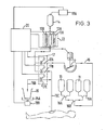
- Figure 3 is a schematic circuit diagram of the apparatus shown in Figure 2.
- In Figure 2, apparatus for peritoneal dialysis includes
dialysate bags 11, a dialysate-feeding unit which, in this instance, is apump 12 which pumps the dialysate from thedialysate bags 11, aheater 13, adialysate storage bag 14 and adialysate discharge meter 15A acting in conjunction with adialysate discharge tank 15 to form a discharge unit. Themembers 11 to 15A are connected bytransfer tubing 16 to form a fluid circuit. The apparatus also includes atransfer tubing switch 17 which changes the direction and branching of the circuit, andload cells - Figure 3 is a schematic circuit diagram of the construction of the apparatus described above, and is useful for explaining its function. In the present invention, the dialysate-feeding unit consists of
dialysate bags 11, which are of the same size and type, positioned at the same height, and connected in parallel with one another byconfluent transfer tubing pump 12. - If a large number of dialysate bags containing dialysate of different compositions are combined as shown in Figure 3, a composite dialysate having a desired osmotic pressure suitable for the condition of the patient can be obtained by combining the several kinds of dialysates when mounting the
dialysate bags 11. The osmotic pressure of the composite dialysate can be finely adjusted by replacing only one of thedialysate bags 11 in accordance with the condition of the patient. It is also possible to use resin or glass bottles instead of bags, but in this case, the interiors of the bottles must be kept at atmospheric pressure. - The composite dialysate prepared in the manner described above is pumped by
pump 12 to thetransfer tubing switch 17. This switch consists of a stricture device having clamps that constrict the transfer tubing, which is flexible at at least this part of the apparatus, to cut off the communication of the fluid or to establish open communication. It is equipped with a metering clamp 17A, aninjection clamp 17B, and adischarge clamp 17C, and the branching and direction of the fluid circuit are altered by instructions from acontroller 20. The dialysate, which is pumped through the tubing bypump 12, passes through the metering clamp 17A and is transferred to thedialysate storage bag 14. During this time, theinjection clamp 17B is kept closed. When the metering clamp 17A opens, the weight of dialysate is measured by theload cell 18A using thedialysate storage bag 14 as a metering bag, and when the weight reaches a predesired weight set in advance in thecontroller 20, thepump 12 is stopped by an instruction from the controller. Next, while the metering clamp 17A and thedischarge clamp 17C are kept closed, theinjection clamp 17B is opened so that the dialysate in thestorage bag 14 is injected into the patient's body through thetransfer tubing 16C by the head of pressure. In the interim, theload cell 18A continues to monitor the weight of thedialysate storage bag 14, so that its change in weight can be used as a means of monitoring the weight of fluid injected. - Finally, the
injection clamp 17B is closed and thedischarge clamp 17C is opened while the metering clamp 17A is kept closed, the discharge passage for the dialysate is opened, so that the dialysate flowing from inside the patient's body flows back through thetransfer tubing 16C, throughdischarge clamp 17C and through transfer tubing 16D intodialysate discharge tank 15. Adialysate discharge meter 15A acting in conjunction withload cell 18B weighs the discharged dialysate in the same manner as that of theload cell 18A. The quantities of dialysate injected and discharged can therefore be determined by calculating the difference between the injected weight and the discharged weight. The discharge operation can be effected simultaneously with the pumping and metering operation of the dialysate into thedialysate storage tank 14. - The
heater 13 consists of aheating bag 13A of a synthetic plastics material through which the dialysate flows, and two flatelectric heaters controller 20, and sandwich theheating bag 13A between them so as to heat the dialysate by thermal conduction. Since the apparatus of the present invention does not use hot water or the like as the heating medium, as in the conventional prior-art apparatus, the size of the dialyser as a whole can be made more compact and the control and use of the apparatus becomes much easier. Moreover, the use of this heater avoids the need for a circulation circuit for heating, and the dialysate can be kept at the optimum temperature by heating only the dialysate flowing through theheating bag 13A, both when the dialysate is being pumped into the dialysate storage unit, and when it is being injected into the human body. - - The
pump 12, theheater 13, and thetransfer tubing switch 17 are all connected to thecontroller 20 by electric circuits, and the injections and discharge operations of the dialysate are under sequence control based on a timer incorporated within thecontroller 20. Thecontroller 20, which is equipped with calculation means and display means, receives the values of the injections weight and discharged weight as monitored by theload cells - As described above, the automatic apparatus for peritoneal dialysis in accordance with the present invention enables a desired osmotic pressure of the dialysate to be selected by the combination of dialysates of differing osmotic pressures, which have previously been limited to only a few kinds of dialysates in the prior-art apparatus, and can also enable the quantity of dialysate injected into the patient to be delicately set in units of 10 grams. Moreover, temperature control can be easily effected. Since the apparatus, including the structure of the dialysate-feeding unit, the method of measuring the weight, and the position of the heating unit can all be arranged in a closed circuit, the number of connections in the transfer tubing is smaller than that in the prior apparatus, which makes the apparatus of the invention extemely hygienic.
- The above described automatic apparatus of the present invention is easy for a doctor or nurse to handle, has a reduced likelihood of bacterial contamination, and can control the quality, quantity and temperature of the dialysate according to the condition of the patient.
Claims (6)
Applications Claiming Priority (2)
| Application Number | Priority Date | Filing Date | Title |
|---|---|---|---|
| JP57215497A JPS59105458A (en) | 1982-12-10 | 1982-12-10 | Automatic abdominal membrane irrigation apparatus |
| JP215497/82 | 1982-12-10 |
Publications (3)
| Publication Number | Publication Date |
|---|---|
| EP0112104A2 true EP0112104A2 (en) | 1984-06-27 |
| EP0112104A3 EP0112104A3 (en) | 1984-09-26 |
| EP0112104B1 EP0112104B1 (en) | 1988-05-18 |
Family
ID=16673364
Family Applications (1)
| Application Number | Title | Priority Date | Filing Date |
|---|---|---|---|
| EP83307358A Expired EP0112104B1 (en) | 1982-12-10 | 1983-12-02 | Apparatus for peritoneal dialysis |
Country Status (3)
| Country | Link |
|---|---|
| EP (1) | EP0112104B1 (en) |
| JP (1) | JPS59105458A (en) |
| DE (1) | DE3376623D1 (en) |
Cited By (15)
| Publication number | Priority date | Publication date | Assignee | Title |
|---|---|---|---|---|
| WO1987006140A1 (en) * | 1986-04-11 | 1987-10-22 | Rolitron Müszaki-Fejlesztö Kisszövetkezet | Process and device for introducing a fluid in human or animal organisms as well as process and heating means for temperature regulation |
| WO1993011829A1 (en) * | 1991-12-10 | 1993-06-24 | Baxter International Inc. | Connector apparatus and system |
| NL1001528C2 (en) * | 1995-10-30 | 1997-05-02 | Cerato B V | Dialysis device. |
| EP0865794A2 (en) * | 1997-03-20 | 1998-09-23 | Konrad Hageneder | Medical liquid disposal device |
| AT404226B (en) * | 1997-03-20 | 1998-09-25 | Hageneder Konrad | Appliance for the disposal of fluids |
| EP0956080A1 (en) * | 1995-11-01 | 1999-11-17 | Femrx, Inc. | System for fluid retention management |
| WO2001019430A1 (en) * | 1999-09-16 | 2001-03-22 | Gambro Lundia Ab | Method and cycler for peritoneal dialysis |
| US6238366B1 (en) | 1996-10-31 | 2001-05-29 | Ethicon, Inc. | System for fluid retention management |
| EP1195171A3 (en) * | 2000-10-04 | 2004-03-03 | Terumo Kabushiki Kaisha | Peritoneal dialysis apparatus |
| US7207966B2 (en) | 1995-11-01 | 2007-04-24 | Ethicon, Inc. | System for fluid retention management |
| EP1872814A1 (en) * | 2006-06-27 | 2008-01-02 | Debiotech S.A. | Medical system for performing a fluidic treatment |
| US9861733B2 (en) | 2012-03-23 | 2018-01-09 | Nxstage Medical Inc. | Peritoneal dialysis systems, devices, and methods |
| US9907897B2 (en) | 2011-03-23 | 2018-03-06 | Nxstage Medical, Inc. | Peritoneal dialysis systems, devices, and methods |
| US11207454B2 (en) | 2018-02-28 | 2021-12-28 | Nxstage Medical, Inc. | Fluid preparation and treatment devices methods and systems |
| US11628242B2 (en) | 2020-09-10 | 2023-04-18 | Fresenius Medical Care Holdings, Inc. | Spent dialysate container for disposing spent dialysate in a dialysis system |
Families Citing this family (6)
| Publication number | Priority date | Publication date | Assignee | Title |
|---|---|---|---|---|
| JPS6053155A (en) * | 1983-09-01 | 1985-03-26 | バクスター、インターナショナル、インコーポレイテッド | Automatic abdominal membrane infusion apparatus |
| JPS6124056U (en) * | 1984-07-18 | 1986-02-13 | 株式会社 日本メデイカル・サプライ | automatic peritoneal irrigation device |
| JP2000107286A (en) * | 1998-10-07 | 2000-04-18 | Akira Sakai | Perfusion apparatus for peritoneal dialyzate and perfusion method |
| JP4837842B2 (en) * | 2001-06-19 | 2011-12-14 | テルモ株式会社 | Peritoneal dialysis machine |
| CN104689397A (en) * | 2015-03-05 | 2015-06-10 | 昆山韦睿医疗科技有限公司 | Peritoneal dialysis system |
| CN104689398B (en) * | 2015-03-05 | 2017-08-29 | 昆山韦睿医疗科技有限公司 | A kind of peritoneal dialysis system and control joint of many liquid bags |
Citations (6)
| Publication number | Priority date | Publication date | Assignee | Title |
|---|---|---|---|---|
| FR2035926A1 (en) * | 1969-03-27 | 1970-12-24 | Thermolyne Corp | |
| DE2734075A1 (en) * | 1976-07-30 | 1978-02-09 | Inst Nat Sante Rech Med | HAEMODIALYSIS METHOD AND EQUIPMENT |
| DE2755214B2 (en) * | 1977-12-10 | 1980-04-10 | Dr. Eduard Fresenius Chemisch-Pharmazeutische Industrie Kg Apparatebau Kg, 6380 Bad Homburg | Device for periodic irrigation of the abdominal cavity |
| GB2052303A (en) * | 1979-06-01 | 1981-01-28 | Instrumentarium Oy | Dialysis apparatus |
| EP0028371A1 (en) * | 1979-10-26 | 1981-05-13 | Vincenzo Buoncristiani | Apparatus for the automatic semicontinuous peritoneal dialysis |
| EP0097432A2 (en) * | 1982-06-18 | 1984-01-04 | Joseph E. Dadson | Apparatus for peritoneal dialysis |
Family Cites Families (2)
| Publication number | Priority date | Publication date | Assignee | Title |
|---|---|---|---|---|
| JPS509293A (en) * | 1973-05-29 | 1975-01-30 | ||
| JPS5239333U (en) * | 1975-09-11 | 1977-03-19 |
-
1982
- 1982-12-10 JP JP57215497A patent/JPS59105458A/en active Pending
-
1983
- 1983-12-02 DE DE8383307358T patent/DE3376623D1/en not_active Expired
- 1983-12-02 EP EP83307358A patent/EP0112104B1/en not_active Expired
Patent Citations (6)
| Publication number | Priority date | Publication date | Assignee | Title |
|---|---|---|---|---|
| FR2035926A1 (en) * | 1969-03-27 | 1970-12-24 | Thermolyne Corp | |
| DE2734075A1 (en) * | 1976-07-30 | 1978-02-09 | Inst Nat Sante Rech Med | HAEMODIALYSIS METHOD AND EQUIPMENT |
| DE2755214B2 (en) * | 1977-12-10 | 1980-04-10 | Dr. Eduard Fresenius Chemisch-Pharmazeutische Industrie Kg Apparatebau Kg, 6380 Bad Homburg | Device for periodic irrigation of the abdominal cavity |
| GB2052303A (en) * | 1979-06-01 | 1981-01-28 | Instrumentarium Oy | Dialysis apparatus |
| EP0028371A1 (en) * | 1979-10-26 | 1981-05-13 | Vincenzo Buoncristiani | Apparatus for the automatic semicontinuous peritoneal dialysis |
| EP0097432A2 (en) * | 1982-06-18 | 1984-01-04 | Joseph E. Dadson | Apparatus for peritoneal dialysis |
Cited By (35)
| Publication number | Priority date | Publication date | Assignee | Title |
|---|---|---|---|---|
| EP0242724A1 (en) * | 1986-04-11 | 1987-10-28 | ROLITRON Müszaki-Fejlesztö Kisszövetkezet | Method and device for injection of a liquid into the human or animal body as well as method and heating device for temperature control |
| US4844074A (en) * | 1986-04-11 | 1989-07-04 | Rolitron Muszaki-Fejleszto Kisszovetkezet | Method and apparatus for introducing a fluid into a human or animal organism as well as method and heating device for temperature control |
| WO1987006140A1 (en) * | 1986-04-11 | 1987-10-22 | Rolitron Müszaki-Fejlesztö Kisszövetkezet | Process and device for introducing a fluid in human or animal organisms as well as process and heating means for temperature regulation |
| WO1993011829A1 (en) * | 1991-12-10 | 1993-06-24 | Baxter International Inc. | Connector apparatus and system |
| NL1001528C2 (en) * | 1995-10-30 | 1997-05-02 | Cerato B V | Dialysis device. |
| WO1997016214A1 (en) * | 1995-10-30 | 1997-05-09 | Cerato B.V. | Dialysis device |
| EP0956080A1 (en) * | 1995-11-01 | 1999-11-17 | Femrx, Inc. | System for fluid retention management |
| US7207966B2 (en) | 1995-11-01 | 2007-04-24 | Ethicon, Inc. | System for fluid retention management |
| EP0956080A4 (en) * | 1995-11-01 | 2000-03-15 | Femrx Inc | System for fluid retention management |
| US6238366B1 (en) | 1996-10-31 | 2001-05-29 | Ethicon, Inc. | System for fluid retention management |
| EP0865794A3 (en) * | 1997-03-20 | 1998-12-16 | Konrad Hageneder | Medical liquid disposal device |
| AT404226B (en) * | 1997-03-20 | 1998-09-25 | Hageneder Konrad | Appliance for the disposal of fluids |
| EP0865794A2 (en) * | 1997-03-20 | 1998-09-23 | Konrad Hageneder | Medical liquid disposal device |
| US6319221B1 (en) | 1998-12-14 | 2001-11-20 | Ethicon, Inc. | System for fluid retention management |
| WO2001019430A1 (en) * | 1999-09-16 | 2001-03-22 | Gambro Lundia Ab | Method and cycler for peritoneal dialysis |
| EP1195171A3 (en) * | 2000-10-04 | 2004-03-03 | Terumo Kabushiki Kaisha | Peritoneal dialysis apparatus |
| EP1872814A1 (en) * | 2006-06-27 | 2008-01-02 | Debiotech S.A. | Medical system for performing a fluidic treatment |
| US11135348B2 (en) | 2011-03-23 | 2021-10-05 | Nxstage Medical, Inc. | Peritoneal dialysis systems, devices, and methods |
| US10046100B2 (en) | 2011-03-23 | 2018-08-14 | Nxstage Medical, Inc. | Peritoneal dialysis systems, devices, and methods |
| US11717601B2 (en) | 2011-03-23 | 2023-08-08 | Nxstage Medical, Inc. | Dialysis systems, devices, and methods |
| US11224684B2 (en) | 2011-03-23 | 2022-01-18 | Nxstage Medical, Inc. | Peritoneal dialysis systems, devices, and methods |
| US10610630B2 (en) | 2011-03-23 | 2020-04-07 | Nxstage Medical, Inc. | Peritoneal dialysis systems, devices, and methods |
| US10688234B2 (en) | 2011-03-23 | 2020-06-23 | Nxstage Medical, Inc. | Peritoneal dialysis systems, devices, and methods |
| US10688235B2 (en) | 2011-03-23 | 2020-06-23 | Nxstage Medical, Inc. | Peritoneal dialysis systems, devices, and methods |
| US10898630B2 (en) | 2011-03-23 | 2021-01-26 | Nxstage Medical, Inc. | Peritoneal dialysis systems, devices, and methods |
| US11690941B2 (en) | 2011-03-23 | 2023-07-04 | Nxstage Medical, Inc. | Peritoneal dialysis systems, devices, and methods |
| US9907897B2 (en) | 2011-03-23 | 2018-03-06 | Nxstage Medical, Inc. | Peritoneal dialysis systems, devices, and methods |
| US10603424B2 (en) | 2011-03-23 | 2020-03-31 | Nxstage Medical, Inc. | Peritoneal dialysis systems, devices, and methods |
| US11433169B2 (en) | 2011-03-23 | 2022-09-06 | Nxstage Medical, Inc. | Dialysis systems, devices, and methods |
| US11433170B2 (en) | 2011-03-23 | 2022-09-06 | Nxstage Medical, Inc. | Dialysis systems, devices, and methods |
| US9861733B2 (en) | 2012-03-23 | 2018-01-09 | Nxstage Medical Inc. | Peritoneal dialysis systems, devices, and methods |
| US11364328B2 (en) | 2018-02-28 | 2022-06-21 | Nxstage Medical, Inc. | Fluid preparation and treatment devices methods and systems |
| US11872337B2 (en) | 2018-02-28 | 2024-01-16 | Nxstage Medical, Inc. | Fluid preparation and treatment devices methods and systems |
| US11207454B2 (en) | 2018-02-28 | 2021-12-28 | Nxstage Medical, Inc. | Fluid preparation and treatment devices methods and systems |
| US11628242B2 (en) | 2020-09-10 | 2023-04-18 | Fresenius Medical Care Holdings, Inc. | Spent dialysate container for disposing spent dialysate in a dialysis system |
Also Published As
| Publication number | Publication date |
|---|---|
| JPS59105458A (en) | 1984-06-18 |
| EP0112104A3 (en) | 1984-09-26 |
| DE3376623D1 (en) | 1988-06-23 |
| EP0112104B1 (en) | 1988-05-18 |
Similar Documents
| Publication | Publication Date | Title |
|---|---|---|
| EP0112104A2 (en) | Apparatus for peritoneal dialysis | |
| EP2116269B1 (en) | Blood purification system | |
| US4728433A (en) | Ultrafiltration regulation by differential weighing | |
| US6595944B2 (en) | Dialysis machine and method of operating a dialysis machine | |
| US5141493A (en) | Peritoneal dialysis system | |
| US4267040A (en) | Hemodialysis apparatus | |
| US5344568A (en) | Hemofiltration system and method | |
| EP1543853B1 (en) | Blood purifying device | |
| CA2134075C (en) | User interface for automated peritoneal dialysis systems | |
| US3620215A (en) | Apparatus for peritoneal dialysis | |
| EP1434646B1 (en) | Method and apparatus for controlling a dialysis apparatus | |
| US4191646A (en) | Apparatus for conducting fluids in a dialysis system | |
| EP0643591B1 (en) | Peritoneal dialysis systems employing a liquid distribution and pump cassette with self-contained air isolation and removal | |
| JP2607798Y2 (en) | System for performing continuous peritoneal dialysis | |
| EP0856321B1 (en) | Pumping apparatus for a peritoneal dialysis system | |
| JPS63122462A (en) | Treatment apparatus for extracorporeal circulation blood | |
| JPH0352296B2 (en) | ||
| EP0659092A1 (en) | Peritoneal dialysis system | |
| JPH0211262B2 (en) | ||
| CN112823325B (en) | Fluid warming device of extracorporeal blood treatment equipment and detection method of fluid temperature at outlet of fluid warming device | |
| EP1261386A2 (en) | Method and system for hemodialysis for use in a non-clinical environment | |
| JP2000084070A (en) | Peritoneal dialysis device | |
| JPH01201263A (en) | Ultrafiltration control device | |
| JP4172261B2 (en) | Continuous blood purification device | |
| KR100652083B1 (en) | Blood purifying device |
Legal Events
| Date | Code | Title | Description |
|---|---|---|---|
| PUAI | Public reference made under article 153(3) epc to a published international application that has entered the european phase |
Free format text: ORIGINAL CODE: 0009012 |
|
| AK | Designated contracting states |
Designated state(s): DE FR GB SE |
|
| PUAL | Search report despatched |
Free format text: ORIGINAL CODE: 0009013 |
|
| AK | Designated contracting states |
Designated state(s): DE FR GB SE |
|
| 17P | Request for examination filed |
Effective date: 19850306 |
|
| 17Q | First examination report despatched |
Effective date: 19860327 |
|
| GRAA | (expected) grant |
Free format text: ORIGINAL CODE: 0009210 |
|
| AK | Designated contracting states |
Kind code of ref document: B1 Designated state(s): DE FR GB SE |
|
| REF | Corresponds to: |
Ref document number: 3376623 Country of ref document: DE Date of ref document: 19880623 |
|
| ET | Fr: translation filed | ||
| PLBE | No opposition filed within time limit |
Free format text: ORIGINAL CODE: 0009261 |
|
| STAA | Information on the status of an ep patent application or granted ep patent |
Free format text: STATUS: NO OPPOSITION FILED WITHIN TIME LIMIT |
|
| 26N | No opposition filed | ||
| PGFP | Annual fee paid to national office [announced via postgrant information from national office to epo] |
Ref country code: FR Payment date: 19941025 Year of fee payment: 12 |
|
| PGFP | Annual fee paid to national office [announced via postgrant information from national office to epo] |
Ref country code: GB Payment date: 19941201 Year of fee payment: 12 |
|
| PGFP | Annual fee paid to national office [announced via postgrant information from national office to epo] |
Ref country code: SE Payment date: 19941216 Year of fee payment: 12 |
|
| REG | Reference to a national code |
Ref country code: FR Ref legal event code: CD |
|
| PGFP | Annual fee paid to national office [announced via postgrant information from national office to epo] |
Ref country code: DE Payment date: 19950124 Year of fee payment: 12 |
|
| EAL | Se: european patent in force in sweden |
Ref document number: 83307358.8 |
|
| PG25 | Lapsed in a contracting state [announced via postgrant information from national office to epo] |
Ref country code: GB Effective date: 19951202 |
|
| PG25 | Lapsed in a contracting state [announced via postgrant information from national office to epo] |
Ref country code: SE Effective date: 19951203 |
|
| GBPC | Gb: european patent ceased through non-payment of renewal fee |
Effective date: 19951202 |
|
| PG25 | Lapsed in a contracting state [announced via postgrant information from national office to epo] |
Ref country code: FR Effective date: 19960830 |
|
| PG25 | Lapsed in a contracting state [announced via postgrant information from national office to epo] |
Ref country code: DE Effective date: 19960903 |
|
| REG | Reference to a national code |
Ref country code: FR Ref legal event code: ST |