EP0112295A2 - Pressure cooker for food for use in a microwave range - Google Patents
Pressure cooker for food for use in a microwave range Download PDFInfo
- Publication number
- EP0112295A2 EP0112295A2 EP83810589A EP83810589A EP0112295A2 EP 0112295 A2 EP0112295 A2 EP 0112295A2 EP 83810589 A EP83810589 A EP 83810589A EP 83810589 A EP83810589 A EP 83810589A EP 0112295 A2 EP0112295 A2 EP 0112295A2
- Authority
- EP
- European Patent Office
- Prior art keywords
- pressure
- pressure vessel
- microwave
- vessel according
- food
- Prior art date
- Legal status (The legal status is an assumption and is not a legal conclusion. Google has not performed a legal analysis and makes no representation as to the accuracy of the status listed.)
- Withdrawn
Links
Images

Classifications
-
- A—HUMAN NECESSITIES
- A47—FURNITURE; DOMESTIC ARTICLES OR APPLIANCES; COFFEE MILLS; SPICE MILLS; SUCTION CLEANERS IN GENERAL
- A47J—KITCHEN EQUIPMENT; COFFEE MILLS; SPICE MILLS; APPARATUS FOR MAKING BEVERAGES
- A47J36/00—Parts, details or accessories of cooking-vessels
- A47J36/02—Selection of specific materials, e.g. heavy bottoms with copper inlay or with insulating inlay
- A47J36/027—Cooking- or baking-vessels specially adapted for use in microwave ovens; Accessories therefor
-
- A—HUMAN NECESSITIES
- A47—FURNITURE; DOMESTIC ARTICLES OR APPLIANCES; COFFEE MILLS; SPICE MILLS; SUCTION CLEANERS IN GENERAL
- A47J—KITCHEN EQUIPMENT; COFFEE MILLS; SPICE MILLS; APPARATUS FOR MAKING BEVERAGES
- A47J27/00—Cooking-vessels
- A47J27/08—Pressure-cookers; Lids or locking devices specially adapted therefor
- A47J27/088—Pressure-cookers; Lids or locking devices specially adapted therefor adapted to high-frequency heating
Definitions
- the invention relates to a steam pressure vessel for the preparation of food, with a container and a pressure-tight lid, and its use in a microwave oven.
- the water vapor is directly affected by microwaves in the vessel water is generated.
- the effect on the cookware is therefore twofold: on the one hand direct microwave radiation and absorption and on the other hand the influence of water vapor under excess pressure and elevated ambient temperature. This enables food to be defrosted and cooked gently and in an energy-saving manner in a short time.
- the whole pressure vessel i.e. Lid and container made of polypropylene.
- This has the advantage of low porosity (compared to ceramics that can also be used), so that no fat deposits can form in the walls, which would absorb microwave energy and thus lead to excessive heating in the walls.
- polypropylene has better mechanical properties than material for pressure vessels.
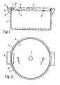
- FIG. 1 and 2 show an embodiment of the steam pressure vessel according to the invention which has a container 1 and a cover 2 which can be placed thereon in a pressure-tight manner.
- Lid and container are out Injection molded polypropylene and have a wall thickness of approx. 10 mm.
- the plan of the vessel is circular, which ensures an optimal distribution of forces in the pressure state. Since the heat transfer does not take place through the vessel walls, e.g. the bottom, but rather the heat is generated in the vessel itself, the design of the vessel shape is not limited by the requirements in this regard. In particular, the bottom of the container can be slightly curved in order to achieve good standing properties.
- an annular projection 8 is formed on the inside of the container wall 1 as a support for the cover 2.
- a groove 8 extends in the container wall to receive a sealing ring 3 with pull tab 10.
- the sealing ring with tab is made of silicone rubber, the material properties are used in Mikrowellenfeld.gelast.
- the cover 2 and the edge of the container can also be shaped such that the cover engages over the container edge and can be fastened to it in the manner of a bayonet catch.
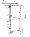
- stems are to be provided on the container and lid, which allow the lid to be attached and detached (FIG. 5).
- the cover 2 is essentially flat trained and has a central handle 7 for placing and lifting the lid. Furthermore, bores 4 and 5 are arranged therein for mounting an overpressure safety device 11 and an adjustable overpressure valve.
- the overpressure safety device 11 (FIG. 3) consists of a crushing plate 12 made of plastic, over which a protective cover 13, also made of plastic, is screwed to the cover 2.
- the breaking plate 12 is dimensioned in such a way that it opens at 1.5 bar in the event that the pressure relief valve fails or a sudden, sharp rise in pressure occurs.
- the broken crushing plate 12 can be easily replaced.
- the pressure relief valve 14 (FIG. 4) is screwed into one of the bores 4, 5. It is infinitely adjustable to pressures between 0 and 1.1 bar in that the preload of a valve spring 18, which presses a valve body 17 against the valve side, can be adjusted by screwing in a valve cover 15 to a greater or lesser extent.
- the cover 2 also has a coupling for connecting a pressure hose made of thick-walled silicone rubber.
- the hose is connected to a manometer, which is provided in the microwave oven and can be observed from the outside. This measure is particularly advantageous in the case of large-volume vessels for use in gastronomy and industry, since it is possible to monitor the pressure curve.
- the pressure vessel has a cover 2 with a stem 20, in which a pressure connection 21 is integrated.
- a corresponding Bore connects the interior of the pressure vessel with an orifice at the end of the stem 20.
- the pressure relief arrangement 25 has a valve which is opened by opening the cooking chamber door of the oven, so that pressure relief takes place in the vessel 2. Then the .Vessel can be pulled from the quick coupling 22 without pressure and opened immediately, since it is connected to the outside through the bore.
- the vessel can be provided with a safety valve 26 instead of a crushing plate.
- This version has the advantage that it can be used safely by laypersons, as pressure relief is automatically set when the oven door is opened.
- the vessels provided with the food to be cooked and some water are closed and placed in a microwave device of a type known per se.
- the water is heated in the microwave field until steam is formed.
- the steam temperature is approx. 130 C.
- the food is heated directly by the microwaves. The combination of the two effects ensures gentle, energy-saving thawing and cooking of the (possibly frozen) food.
- the microwaves act directly on the water or steam, ie the heat is not supplied by heat conduction, the steam pressure or steam temperature can be influenced more quickly than with conventional steam cookers.
- the vessel described can be used in microwave devices for the household, catering and industry, its volume being adapted to the available microwave device.
Abstract
Description
Die Erfindung betrifft ein Dampfdruckgefäss für die Zubereitung von Nahrungsmitteln, mit einem Behälter und einem druckdicht aufsetzbaren Deckel, sowie dessen Verwendung in einem Mikrowellengerät.The invention relates to a steam pressure vessel for the preparation of food, with a container and a pressure-tight lid, and its use in a microwave oven.
Es ist bekannt, dass Nahrungsmittel unter dem Einfluss von Mikrowellen schonend und in kurzer Zeit aufgetaut und gegart werden können. Dabei werden die Wasser- und Fettmoleküle in den Nahrungsmitteln von den eindringenden Mikrowellen angeregt, woraus sich ein Erwärmungseffekt ergibt. Andererseits ist es ebenfalls bekannt, Nahrungsmittel im Dampfkochtopf unter Ueberdruck im Wasserdampf zu garen. Dabei wird die Wärme in der Regel durch Wärmeleitung auf den Dampfkochtopf übertragen und unter dem Einfluss dieser Wärme Wasser verdampft, was eine relativ lange Aufwärmzeit beansprucht und Energieverluste nach sich zieht. Mit der Erfindung wird bezweckt, diese Nachteile zu vermeiden.It is known that food can be thawed and cooked gently and quickly under the influence of microwaves. The water and fat molecules in the food are stimulated by the penetrating microwaves, which results in a heating effect. On the other hand, it is also known to cook food in the pressure cooker under excess pressure in the steam. The heat is usually transferred to the pressure cooker by heat conduction and water is evaporated under the influence of this heat, which takes a relatively long warm-up time and results in energy losses. The aim of the invention is to avoid these disadvantages.
Dies gelingt mittels eines Dampfdruckgefässes nach Anspruch 1 und dessen Verwendung in einem Mikrowellengerät.This is achieved by means of a steam pressure vessel according to
Dabei wird der Wasserdampf unmittelbar durch die Einwirkung von Mikrowellen auf im Gefäss befindliches Wasser erzeugt. Die Wirkung auf das Kochgut Lst damit eine zweifache: einerseits direkte MikrowelLenbestrahlung und-absorption und andererseits Einwircung des Wasserdampfes unter Ueberdruck und erhöhter Umgebungstemperatur. Damit gelingt es, Lebensmittel schonend und energiesparend in kurzer Zeit aufzutauen und zu garen.The water vapor is directly affected by microwaves in the vessel water is generated. The effect on the cookware is therefore twofold: on the one hand direct microwave radiation and absorption and on the other hand the influence of water vapor under excess pressure and elevated ambient temperature. This enables food to be defrosted and cooked gently and in an energy-saving manner in a short time.
Vorzugsweise ist das ganze Druckgefäss, d.h. Deckel und Behälter aus Polypropylen ausgebildet. Dieses hat den Vorteil geringer Porosität (im Vergleich etwa zu ebenfalls verwendbaren Keramik), so dass sich keine Fettanlagerungen in den Wänden bilden können, welche Mikrowellenenergie absorbieren und damit zu starken Erwärmungen in den Wänden führen würden. Im Vergleich zum ebenfalls verwendbaren Glas besitzt Polypropylen bessere mechanische Eigenschaften als Material für Druckgefässe.Preferably the whole pressure vessel, i.e. Lid and container made of polypropylene. This has the advantage of low porosity (compared to ceramics that can also be used), so that no fat deposits can form in the walls, which would absorb microwave energy and thus lead to excessive heating in the walls. Compared to the glass that can also be used, polypropylene has better mechanical properties than material for pressure vessels.
Nachfolgend wird ein Ausführungsbeispiel der Erfindung anhand der beiliegenden Zeichnung näher beschrieben. Darin zeigen:
- Fig. 1 eine Schnittansicht eines Dampfdruckgefässes nach der Erfindung;
- Fig. 2 eine Aufsicht auf das Gefäss nach Fig. l;
- Fig. 3-eine Ueberdruckzwangssicherung in Schnittansicht zur Anbringung am Dampfdruckgefäss nach Fig. 1;
- Fig. 4 ein einstellbares Ueberdruckventil in Schnittansicht zur Anbringung am Dampfdruckgefäss nach Fig. l, und
- Fig. 5 eine Schnittansicht einer weiteren Ausführungsform der Erfindung.
- Figure 1 is a sectional view of a steam pressure vessel according to the invention.
- Fig. 2 is a plan view of the vessel of Fig. 1;
- 3 shows an overpressure safety device in a sectional view for attachment to the steam pressure vessel according to FIG. 1;
- F ig. 4 an adjustable pressure relief valve in a sectional view for attachment to the steam pressure vessel according to FIG. 1, and
- Fig. 5 is a sectional view of another embodiment of the invention.
In den Fig. 1 und 2 ist eine Ausführung des erfindungsgemässen Dampfdruckgefässes gezeigt, das einen Behälter 1 und einen druckdicht darauf aufsetzbaren Deckel 2 besitzt. Deckel und Behälter sind aus Polypropylen gespritzt und weisen eine Wandstärke von ca. 10 mm auf. Die Grundrissform des Gefässes ist kreisrund, was eine optimale Kräfteverteilung im Druckzustand gewährleistet. Da die Wärmeübertragung nicht durch die Gefässwände, z.B..den Boden, erfolgt, sondern die Wärmeerzeugung im Gefäss selbst stattfindet, ist die Auslegung der Gefässform-nicht durch diesbezügliche Anforderungen beschränkt. Insbesondere kann der Behälterboden leicht gewölbt ausgebildet sein, um gute Standeigenschaften zu erreichen.1 and 2 show an embodiment of the steam pressure vessel according to the invention which has a
Wie aus Fig. 1 ersichtlich ist, ist in die Behälterwand 1 innenseitig ein ringartiger Vorsprung 8 als Auflager für den Deckel 2 eingeformt. Um die Deckelwandstärke nach oben-versetzt, verläuft eine Nut 8 in der Behälterwand zur Aufnahme eines Dichtungsringes 3 mit Zuglasche 10. Der Dichtungsring mit Lasche besteht aus Silikongummi, dessen Materialeigenschaften zum Einsatz im Mikrowellenfeld.geeignet sind. Beim Aufbau des Dampfdruckes im Gefäss wird der Deckel 2 nach oben gegen den Dichtungsring 3 gepresst, wodurch ein druckdichter Abschluss entsteht. An der Behälteraussenseite sind zwei Traggriffe 6 angeformt, welche einen Stiel überflüssig machen. Dies erlaubt eine bessere Raumausnutzung im Mikrowellengerät.As can be seen from FIG. 1, an annular projection 8 is formed on the inside of the
Als mögliche Abwandlung des beschriebenen Ausführungsbeispieles kann der Deckel 2 und der Rand des Behälter auch derart geformt sein, dass der Deckel den Behälterrand übergreift und in der Art eines Bajonettverschlusses daran befestigbar ist. Bei einer solchen, konstruktiv aufwendigeren.Ausführung sind allerdings Stiele an Behälter und Deckel vorzusehen, welche das Befestigen und Lösen des Deckels erlauben (Fig. 5).As a possible modification of the described embodiment, the
Bei dem in den Fig. 1 und 2 gezeigten Ausführungsbeispiel ist der Deckel 2 im wesentlichen eben ausgebildet und besitzt einen zentralen Griff 7 zum Aufsetzen und Abheben des Deckels. Ferner sind darin Bohrungen 4 und 5 zur Montage einer Ueberdruckzwangssicherung 11 und eines einstellbaren Ueberdruckventils angeordnet.In the embodiment shown in FIGS. 1 and 2, the
Die Ueberdruckzwangssicherung 11 (Fig. 3) besteht aus einer Brechplatte 12 aus Kunststoff, über welcher ein Schutzdeckel 13, ebenfalls aus Kunststoff, am Deckel 2 festgeschraubt ist. Die.Brechplatte 12 ist so dimensioniert, dass sie bei 1.5 bar öffnet, falls das Ueberdruckventil versagt oder ein plötzlicher starker Druckanstieg auftritt. Die gebrochene Brechplatte 12 kann leicht ausgewechselt werden.The overpressure safety device 11 (FIG. 3) consists of a crushing
Das Ueberdruckventil 14 (Fig. 4) wird in eine der Bohrungen 4,5 eingeschraubt. Es ist.stufenlos auf Drucke zwischen 0 und 1.1 bar einstellbar, indem die Vorspannung einer Ventilfeder 18, die einen-Ventilkörper 17 gegen den Ventilseitz presst, durch mehr oder weniger tiefes Einschrauben eines Ventildeckels 15 verstellbar ist.The pressure relief valve 14 (FIG. 4) is screwed into one of the
Bei einem nicht gezeigten Ausführungsbeispiel weist der Deckel 2 überdies eine Kupplung zum Anschluss eines Druckschlauches aus dickwandigem Silikongummi auf. Der Schlauch wird an ein Manometer angeschlossen, das im Mikrowellengerät vorgesehen und von aussen beobachtbar ist. Diese Massnahme ist insbesondere bei grossvolumigen Gefässen zur Verwendung in der Gastronomie und Industrie vorteilhaft, indem eine Ueberwachung des Druckverlaufes möglich ist.In an embodiment not shown, the
In Fig. 5 ist eine weitere Ausführung dargestellt, welche im wesentlichen der vorbeschriebenen entspricht, so dass hier nur auf die Abwandlungen vom Beschriebenen eingegangen wird. Das Druckgefäss weist einen Deckel 2 mit einem Stiel 20 auf, in den ein Druckanschluss 21 integriert ist. Eine entsprechende Bohrung verbindet den Innenraum des Druckgefässes mit einer Mündung am Ende des Stiels 20. Damit wird das Gefäss beim Einschieben auf der Bodenplatte 28 in den Mikrowellenherd mittels einer an der Rückwand des Herdes angeordneten, dichtenden Schnellkupplung 22 mit einer Leitung im Herd verbunden, die einerseits über ein Ventil 24 zu einem Manometer 23 führt.und andererseits mit einer Druckablassanordnung 25 verbunden ist. Die Druckablassandordnung 25 weist ein Ventil auf, das durch das Oeffnen der Garraumtüre des Herdes geöffnet wird, so dass eine Druckentlastung im Gefäss 2 stattfindet. Danach kann das .Gefäss drucklos aus der Schnellkupplung 22 gezogen und unmittelbar geöffnet werden, da es durch die Bohrung mit der Aussenseite verbunden ist. Das Gefäss kann statt mit einer Brechplatte.mit einem Sicherheitsventil 26 versehen sein.5 shows a further embodiment which essentially corresponds to that described above, so that only the modifications of what has been described are discussed here. The pressure vessel has a
Diese Ausführung hat den Vorteil einer gefahrlosen Verwendung auch durch Laien, indem sich beim Oeffnen der Garraumtüre automatisch eine Druckentlastung einstellt.This version has the advantage that it can be used safely by laypersons, as pressure relief is automatically set when the oven door is opened.
Für den Betrieb werdezdie mit dem Kochgut und etwas Wasser versehenenGefässe verschlossen und in ein Mikrowellengerät an sich bekannter Bauart eingesetzt. Im Mikrowellenfeld wird das Wasser bis zur Dampfbildung erwärmt. Bei einem Dampfüberdruck von ca. 1.1 bar beträgt die Dampftemperatur ca. 130 C. Zugleich wird das Kochgut durch.die Mikrowellen direkt erhitzt. Die Kombination der beiden Einwirkungen gewährleistet ein schonendes, energiesparendes Auftauen und Garen des (ev. tiefgefrorenen) Kochgutes.For the operation, the vessels provided with the food to be cooked and some water are closed and placed in a microwave device of a type known per se. The water is heated in the microwave field until steam is formed. At a steam pressure of approx. 1.1 bar, the steam temperature is approx. 130 C. At the same time, the food is heated directly by the microwaves. The combination of the two effects ensures gentle, energy-saving thawing and cooking of the (possibly frozen) food.
Da die Einwirkung der Mikrowellen auf das Wasser bzw. den Dampf direkt erfolgt, die Wärme also nicht durch Wärmeleitung zugeführt wird, kann der Dampfdruck bzw. die Dampftemperatur rascher beeinflusst werden, als bei herkömmlichen Dampfkochgefässen.Since the microwaves act directly on the water or steam, ie the heat is not supplied by heat conduction, the steam pressure or steam temperature can be influenced more quickly than with conventional steam cookers.
Das beschriebene Gefäss kann in Mikrowellengeräten für den Haushalt, die Gastronomie sowie die Industrie verwendet werden, wobei sein Volumen dem zur Verfügung stehenden Mikrowellengerät angepasst ist.The vessel described can be used in microwave devices for the household, catering and industry, its volume being adapted to the available microwave device.
Es verlangt keine besondere Anordnung des Mikrowellenfeldes, weil das Gefäss selbst das Feld nicht wesentlich beeinflusst.No special arrangement of the microwave field is required because the vessel itself does not significantly influence the field.
Claims (11)
Applications Claiming Priority (2)
| Application Number | Priority Date | Filing Date | Title |
|---|---|---|---|
| CH730282 | 1982-12-15 | ||
| CH7302/82 | 1982-12-15 |
Publications (2)
| Publication Number | Publication Date |
|---|---|
| EP0112295A2 true EP0112295A2 (en) | 1984-06-27 |
| EP0112295A3 EP0112295A3 (en) | 1984-07-25 |
Family
ID=4323009
Family Applications (1)
| Application Number | Title | Priority Date | Filing Date |
|---|---|---|---|
| EP83810589A Withdrawn EP0112295A3 (en) | 1982-12-15 | 1983-12-14 | Pressure cooker for food for use in a microwave range |
Country Status (1)
| Country | Link |
|---|---|
| EP (1) | EP0112295A3 (en) |
Cited By (17)
| Publication number | Priority date | Publication date | Assignee | Title |
|---|---|---|---|---|
| EP0288862A1 (en) * | 1987-04-18 | 1988-11-02 | Kabushiki Kaisha Nakamuraya | Container with whistling device for thermally cooking food |
| JPH01175626U (en) * | 1988-05-25 | 1989-12-14 | ||
| WO1990006461A1 (en) * | 1988-11-25 | 1990-06-14 | Lautenschlaeger Werner | Sample container for the digestion of sample material |
| WO1990015515A1 (en) * | 1989-06-07 | 1990-12-13 | Wolfgang Moshammer | Process and device for irradiating material containing or mixed with water with microwave energy |
| EP0438080A1 (en) * | 1990-01-11 | 1991-07-24 | Matsushita Electric Industrial Co., Ltd. | A pressure cooker |
| JPH0395820U (en) * | 1990-01-19 | 1991-09-30 | ||
| DE4133524C1 (en) * | 1991-10-10 | 1993-04-29 | Fissler Gmbh, 6580 Idar-Oberstein, De | |
| DE19601071A1 (en) * | 1996-01-13 | 1997-07-24 | Achim Luft | Pressurised packaging container with lid, seal and container |
| DE102005060290B3 (en) * | 2005-12-15 | 2006-12-21 | Ritter Gmbh | Stiff, one-time haemodialysis salt container has sealing foil bridging ventilation opening that breaks on reaching defined pressure difference between air pressure outside container, reduced pressure inside produced by dialysis device |
| USD673808S1 (en) | 2012-03-10 | 2013-01-08 | Wki Holding Company, Inc. | Container lid |
| USD673807S1 (en) | 2012-03-10 | 2013-01-08 | Wki Holding Company, Inc. | Container lid |
| USD675057S1 (en) | 2012-03-09 | 2013-01-29 | Wki Holding Company, Inc. | Lid |
| US8376181B2 (en) | 2010-05-21 | 2013-02-19 | Wki Holding Company, Inc. | Container assembly with flexible lid seal and releasing arrangement |
| JP2013120004A (en) * | 2011-12-07 | 2013-06-17 | Panasonic Corp | High-frequency heating device |
| EP2604399A3 (en) * | 2011-12-13 | 2013-09-04 | Weber Maschinenbau GmbH Breidenbach | Device for processing food products |
| US8733550B2 (en) | 2012-03-09 | 2014-05-27 | Wki Holding Company, Inc. | Nesting container lids with snap on wings |
| US8899443B2 (en) | 2008-12-15 | 2014-12-02 | Wki Holding Company, Inc. | Container assembly with flexible seal |
Citations (8)
| Publication number | Priority date | Publication date | Assignee | Title |
|---|---|---|---|---|
| US1546127A (en) * | 1921-10-13 | 1925-07-14 | Frederick S Hadley | Apparatus for cooking |
| CH273354A (en) * | 1947-09-11 | 1951-02-15 | Fritjof Andersson Bjorn | Pressure cooker. |
| US2622187A (en) * | 1947-01-14 | 1952-12-16 | Raytheon Mfg Co | Microwave pressure cooker |
| DE867289C (en) * | 1950-09-29 | 1953-02-16 | Franz Lautenschlaeger | Steam sterilizer for sterilization containers placed one behind the other |
| FR1077042A (en) * | 1953-03-18 | 1954-11-03 | Multipurpose kitchen implement | |
| GB741678A (en) * | 1952-03-29 | 1955-12-07 | Harald Nissen | Improvements in or relating to a method of heat treating the contents of closed containers |
| US3941967A (en) * | 1973-09-28 | 1976-03-02 | Asahi Kasei Kogyo Kabushiki Kaisha | Microwave cooking apparatus |
| US3983260A (en) * | 1974-09-20 | 1976-09-28 | Ball Corporation | Quick cooling pressure cooker system |
-
1983
- 1983-12-14 EP EP83810589A patent/EP0112295A3/en not_active Withdrawn
Patent Citations (8)
| Publication number | Priority date | Publication date | Assignee | Title |
|---|---|---|---|---|
| US1546127A (en) * | 1921-10-13 | 1925-07-14 | Frederick S Hadley | Apparatus for cooking |
| US2622187A (en) * | 1947-01-14 | 1952-12-16 | Raytheon Mfg Co | Microwave pressure cooker |
| CH273354A (en) * | 1947-09-11 | 1951-02-15 | Fritjof Andersson Bjorn | Pressure cooker. |
| DE867289C (en) * | 1950-09-29 | 1953-02-16 | Franz Lautenschlaeger | Steam sterilizer for sterilization containers placed one behind the other |
| GB741678A (en) * | 1952-03-29 | 1955-12-07 | Harald Nissen | Improvements in or relating to a method of heat treating the contents of closed containers |
| FR1077042A (en) * | 1953-03-18 | 1954-11-03 | Multipurpose kitchen implement | |
| US3941967A (en) * | 1973-09-28 | 1976-03-02 | Asahi Kasei Kogyo Kabushiki Kaisha | Microwave cooking apparatus |
| US3983260A (en) * | 1974-09-20 | 1976-09-28 | Ball Corporation | Quick cooling pressure cooker system |
Cited By (27)
| Publication number | Priority date | Publication date | Assignee | Title |
|---|---|---|---|---|
| AU616882B2 (en) * | 1987-04-18 | 1991-11-14 | Furubayashi Shiko Kabushiki Kaisha | Container with whistling device for thermally cooking food |
| EP0288862A1 (en) * | 1987-04-18 | 1988-11-02 | Kabushiki Kaisha Nakamuraya | Container with whistling device for thermally cooking food |
| JPH01175626U (en) * | 1988-05-25 | 1989-12-14 | ||
| WO1990006461A1 (en) * | 1988-11-25 | 1990-06-14 | Lautenschlaeger Werner | Sample container for the digestion of sample material |
| WO1990015515A1 (en) * | 1989-06-07 | 1990-12-13 | Wolfgang Moshammer | Process and device for irradiating material containing or mixed with water with microwave energy |
| US5122633A (en) * | 1989-06-07 | 1992-06-16 | Wolfgang Moshammer | Method and apparatus for radiation microwave energy into material containing water or mixed with water |
| US5229563A (en) * | 1990-01-11 | 1993-07-20 | Matsushita Electric Industrial Co., Ltd. | Pressure cooker |
| EP0438080A1 (en) * | 1990-01-11 | 1991-07-24 | Matsushita Electric Industrial Co., Ltd. | A pressure cooker |
| AU621778B2 (en) * | 1990-01-11 | 1992-03-19 | Matsushita Electric Industrial Co., Ltd. | A pressure cooker |
| JPH0395820U (en) * | 1990-01-19 | 1991-09-30 | ||
| DE4133524C2 (en) * | 1991-10-10 | 1996-08-29 | Fissler Gmbh | Pressure cooker |
| US5297473A (en) * | 1991-10-10 | 1994-03-29 | Fissler Gmbh | Pressure cooker |
| DE4133524C1 (en) * | 1991-10-10 | 1993-04-29 | Fissler Gmbh, 6580 Idar-Oberstein, De | |
| DE19601071A1 (en) * | 1996-01-13 | 1997-07-24 | Achim Luft | Pressurised packaging container with lid, seal and container |
| DE19601071C2 (en) * | 1996-01-13 | 1999-03-18 | Achim Luft | Overpressure packaging container and method and device for filling and closing the packaging |
| DE102005060290B3 (en) * | 2005-12-15 | 2006-12-21 | Ritter Gmbh | Stiff, one-time haemodialysis salt container has sealing foil bridging ventilation opening that breaks on reaching defined pressure difference between air pressure outside container, reduced pressure inside produced by dialysis device |
| US9427511B2 (en) | 2005-12-15 | 2016-08-30 | Ritter Gmbh | Hemodialysis salt container with ventilation |
| US8899443B2 (en) | 2008-12-15 | 2014-12-02 | Wki Holding Company, Inc. | Container assembly with flexible seal |
| US8376181B2 (en) | 2010-05-21 | 2013-02-19 | Wki Holding Company, Inc. | Container assembly with flexible lid seal and releasing arrangement |
| JP2013120004A (en) * | 2011-12-07 | 2013-06-17 | Panasonic Corp | High-frequency heating device |
| EP2604399A3 (en) * | 2011-12-13 | 2013-09-04 | Weber Maschinenbau GmbH Breidenbach | Device for processing food products |
| USD675057S1 (en) | 2012-03-09 | 2013-01-29 | Wki Holding Company, Inc. | Lid |
| US8733550B2 (en) | 2012-03-09 | 2014-05-27 | Wki Holding Company, Inc. | Nesting container lids with snap on wings |
| US9187223B2 (en) | 2012-03-09 | 2015-11-17 | Wki Holding Company, Inc. | Nesting container lids with snap on wings |
| US9663276B2 (en) | 2012-03-09 | 2017-05-30 | Wki Holding Company, Inc. | Compressible seal member for container |
| USD673807S1 (en) | 2012-03-10 | 2013-01-08 | Wki Holding Company, Inc. | Container lid |
| USD673808S1 (en) | 2012-03-10 | 2013-01-08 | Wki Holding Company, Inc. | Container lid |
Also Published As
| Publication number | Publication date |
|---|---|
| EP0112295A3 (en) | 1984-07-25 |
Similar Documents
| Publication | Publication Date | Title |
|---|---|---|
| EP0112295A2 (en) | Pressure cooker for food for use in a microwave range | |
| DE2736464C3 (en) | Microwave cooking or baking device | |
| CH686607A5 (en) | High temp. adiabatic cooking device | |
| DE2043631A1 (en) | Electric cooker with a smooth top | |
| DE19729661A1 (en) | Heating system especially for electric cooking operations | |
| DE2851671A1 (en) | DEVICE FOR TREATMENT OF FOOD WITH STEAM | |
| DE102020105146A1 (en) | Cooking device and method of operation | |
| DE4401642A1 (en) | Steam cooking device | |
| DE3026979A1 (en) | COOKER | |
| EP0029179A1 (en) | Combined stove for microwave and for conventional resistance heating | |
| DE1642134A1 (en) | Autoclave | |
| DE4333585A1 (en) | Cooker with a baking chamber usable as a steam-cooking chamber | |
| DE3433794C2 (en) | ||
| DE3618587A1 (en) | Warming-up receptacle | |
| DE3026312C2 (en) | Pressure cooker | |
| DE3337200A1 (en) | Cooking vessel | |
| DE10025825B4 (en) | Cooker for boiling Chinese herbs | |
| DE3941322A1 (en) | Steam cooking device mounted on wall of oven - ensures humidification of cooking space by evapn. of water in container surrounded by electric heating coil | |
| CH652293A5 (en) | Pressure-cooker for pressure-cooking products by means of steam | |
| DE2946766A1 (en) | COMBINED OVEN FOR MICROWAVE AND CONVENTIONAL RESISTANCE HEATING | |
| DE972296C (en) | Cooking vessel, the upper edge of which can be heated by a heated lid | |
| DE3711441C2 (en) | ||
| DE4116592C2 (en) | ||
| DE3343553A1 (en) | Cooking and heating vessel | |
| DE2451130A1 (en) | Pressure cooker with rapid cool down and min of steam - has insulated pressure release chamber drawing off heat to cool inner steam |
Legal Events
| Date | Code | Title | Description |
|---|---|---|---|
| PUAI | Public reference made under article 153(3) epc to a published international application that has entered the european phase |
Free format text: ORIGINAL CODE: 0009012 |
|
| PUAL | Search report despatched |
Free format text: ORIGINAL CODE: 0009013 |
|
| AK | Designated contracting states |
Designated state(s): DE FR GB |
|
| AK | Designated contracting states |
Designated state(s): DE FR GB |
|
| STAA | Information on the status of an ep patent application or granted ep patent |
Free format text: STATUS: THE APPLICATION IS DEEMED TO BE WITHDRAWN |
|
| 18D | Application deemed to be withdrawn |
Effective date: 19850719 |
|
| RIN1 | Information on inventor provided before grant (corrected) |
Inventor name: SANWALD, WILLY |