EP0112498A2 - Apparatus for automatically cleaning windows - Google Patents
Apparatus for automatically cleaning windows Download PDFInfo
- Publication number
- EP0112498A2 EP0112498A2 EP83111698A EP83111698A EP0112498A2 EP 0112498 A2 EP0112498 A2 EP 0112498A2 EP 83111698 A EP83111698 A EP 83111698A EP 83111698 A EP83111698 A EP 83111698A EP 0112498 A2 EP0112498 A2 EP 0112498A2
- Authority
- EP
- European Patent Office
- Prior art keywords
- window
- receiver
- light
- transmitter
- arrangement according
- Prior art date
- Legal status (The legal status is an assumption and is not a legal conclusion. Google has not performed a legal analysis and makes no representation as to the accuracy of the status listed.)
- Granted
Links
Images
Classifications
-
- A—HUMAN NECESSITIES
- A47—FURNITURE; DOMESTIC ARTICLES OR APPLIANCES; COFFEE MILLS; SPICE MILLS; SUCTION CLEANERS IN GENERAL
- A47L—DOMESTIC WASHING OR CLEANING; SUCTION CLEANERS IN GENERAL
- A47L1/00—Cleaning windows
Definitions
- the invention relates to an arrangement for the automatic cleaning of windows according to the preamble of claim 1.
- cloud height and visual measuring devices as well as certain types of distance measuring devices, all of which operate on the principle of optical radar, which means that short light pulses are emitted by a transmitter.
- optical radar which means that short light pulses are emitted by a transmitter.
- the receiver of the measuring device When the light pulse hits a cloud or some other reflective object, reflections occur on that object and a small part of the reflected light is collected by the receiver of the measuring device, which is arranged next to the transmitter. The time it takes for the light to travel the distance from the transmitter to the reflecting object and from this back to the receiver is measured, and from this the cloud height or the line of sight or the distance can be calculated based on the known speed of light.
- Transmitter and receiver are built into a so-called transceiver, which also contains the optics and the necessary electronic equipment.
- the emitted light passes through a transmitter window and the reflected light passes through a receiver window before it reaches a signal detector via the receiver optics.
- window wipers with wiper blades such as those used for cleaning headlights and windows in cars, cannot be used, and also not in conjunction with a washing liquid, since they press relatively strongly against the glass.
- the signals detected by the signal detector are greatly reduced by precipitation in the form of rain and snow on the windows.
- the signals detected by the signal detector are greatly reduced by precipitation in the form of rain and snow on the windows.
- This cleaning must be carried out continuously during the entire period of precipitation in order to keep the windows sufficiently clean.
- the invention has for its object to develop an arrangement of the type mentioned, which ensures reliable and convenient way for an automatic cleaning of windows, and which is particularly suitable for keeping the windows of cloud height and visual measuring devices clean.
- the degree of soiling of the windows is continuously monitored, and as soon as a certain soiling limit is exceeded, a cleaning device is started that removes water and dirt from the window.
- the arrangement is designed so that there are no scratches on the window surfaces. When the windows are clean are or a sufficient degree of cleanliness has been reached, the cleaning device is stopped.
- the arrangement according to the. Invention is designed so that it does not affect the normal course of operation of a cloud height or visual measuring device.
- the window glass used in measuring devices in which measuring radiation passes through the glass is normally treated with anti-reflection in order not to cause greater attenuation of the light signals itself.
- the arrangement according to the invention uses the light reflected in this way as information that a foreign layer, for example rain or snow, is on the outside of the window.
- the logic unit of the cloud height measuring device processes the measured reflection values, and if the measured reflection signal exceeds a certain value, a cleaning device is activated.
- the cleaning device can operate by blowing high pressure air along the window.
- Another possibility is to use a swinging or rotating drying arm that is close to the glass surface lies, has an open gap or a row of holes directed towards the glass, compressed air and / or a rinsing liquid being fed through the hollow drying arm in such a way that a film or a veil of compressed air and / or liquid forms between the drying arm and the glass and slides over the glass.
- the cleaning sequence can be controlled in such a way that rinsing and then drying by blowing with heated high-pressure air are carried out lengthways along the window. If the measured value for the light reflected on the surface of the glass becomes zero or falls below a low comparison value, the cleaning device is stopped.
- the measuring device shown equally in FIGS. 1 and 2 for measuring the cloud height, visibility or a distance comprises parts 1 to 9.
- the measuring device works on the principle of optical radar.
- the transmitter part includes the transmitter 1, the transmitter optics 2 and the transmitter window 3.
- the receiver part includes the receiver window 4, the receiver optics 5, the receiver 6 and the signal detector 7.
- the processor 8 contains the electronic equipment which, among other things, activates the laser transmitter and the Measurement course controls, counts the pulses and transmits data 9 to be written and / or displayed devices.
- the cleaning arrangement according to the invention includes a light guide 10 and a feed element 11 for the cleaning device 12. Otherwise, the cleaning arrangement uses the transmitter and receiver units already present in the measuring device.
- the cleaning arrangement according to FIG. 2 contains its own transmitter 13 with feed element 14 and its own receiver 15 with signal detector 16 as well as the cleaning device 18 with feed element 17, via which the cleaning device is switched on.
- Both embodiments of the invention work on the same principle.
- the foreign layer (dirt, snow, rain) on the outside of the transmitter window is detected by measuring the radiation reflected by this layer. Since the spatial distance between the transmitter window and the receiver window is small, it can be assumed that the foreign layer is the same on both windows. In principle, there can also be a common window for the transmitter and receiver.
- the radiation reflected by the foreign layer e.g. water drops
- the radiation reflected by the foreign layer e.g. water drops
- the transmitter and receiver of the measuring device itself are used to detect a possible foreign layer.
- the light reflected from the outside of the transmitter window 3 is collected and passed directly to the receiver 6 via the light guide 10.
- a special measurement sequence is programmed in the processor 8 for this reflection measurement, and the corresponding reflected signal is processed by the processor.
- the reflection measurement for detecting the foreign layer is controlled by the processor so that it is either before or after a cloud height or visibility measurement done so as not to disturb the latter.
- the value of the measured reflected light is compared in processor 8 with a predetermined comparison value which corresponds to the maximum permissible contamination of the transmitter window. If the comparison value is exceeded, the processor 8 sends a signal to the feed element 11 which sets the cleaning device 12 in motion.
- the cleaning arrangement has its own transmitter 13 with its own feed element 14 for illuminating the transmitter window 3 and its own receptions @ Xit detector 16 for measuring the light reflected from the transmitter window.
- the processor 8 takes on the same function in this cleaning arrangement as in FIG. 1. It therefore controls the transmitter 13 and receiver 15, converts the reflected light into a measured value for the degree of soiling of the window, compares this value with a predetermined comparison value which is the highest permissible pollution corresponds, and activates the feed member 17 of the cleaning device 18 when the measured value exceeds the comparison value.
- the cleaning devices 12 and 18 in FIG. 1 and FIG. 2 are the same device, but, as already mentioned, can be designed in different ways.
- the device can be a high-pressure unit which blows heated air along windows 3 and 4.
- an additional cleaning device can be used to achieve a better cleaning effect.
- the supplement can consist of a back-and-forth or rotating wiper blade with a soft contact edge on the outside of the transmitter window.
- the cleaning process can be programmed, for example, in such a way that first rinsing and then drying by blowing with heated compressed air takes place.
- the cleaning device is automatically stopped after the window has been cleaned, i.e. as soon as no or only a small amount of light is reflected on the outside of the window.
- the measurement can of course be carried out on the transmitter and receiver window or only on one of the windows. If the measurement is carried out on the receiver window, a light guide is used in the embodiment according to FIG. 1, which transmits light from the transmitter for illuminating the receiver window.
- the embodiment according to FIG. 2 can be used for the receiver window in the same way as for the transmitter window. It is also possible to work only with a separate transmitter 13 and, for example, the own receiver 6 of the cloud height measuring device, the receiver 6 collecting the reflections caused by the foreign layer on the window glass. If disturbing reflections from the foreign layer measurement on the glass can occur or if the cloud height measuring system of the cloud height measuring device is used, the measurement of the Foreign window layer are made in such a way that the cloud height or visibility measurement is not disturbed.
Abstract
Description
Die Erfindung betrifft eine Anordnung zur selbsttätigen Reinigung von Fenstern gemäß dem Oberbegriff des Anspruches 1.The invention relates to an arrangement for the automatic cleaning of windows according to the preamble of claim 1.
Ein wichtiges Anwendungsgebiet für eine solche Anordnung sind Wolkenhöhen- und Sichtmeßgeräte sowie bestimmte Arten von Abstandsmeßgeräten, die alle nach dem Prinzip des optischen Radars arbeiten, was bedeutet, daß kurze Lichtimpulse von einem Sender ausgesandt werden. Wenn der Lichtimpuls eine Wolke oder irgendeinen anderen reflektierenden Gegenstand trifft, treten an diesem Gegenstand Reflexionen auf, und ein kleiner Teil des reflektierten Lichtes wird von dem Empfänger des Meßgerätes, der neben dem Sender angeordnet ist, aufgefangen. Die Zeit, die das Licht für das Durchlaufen der Strecke vom Sender zum reflektierenden Gegenstand und von diesem zurück zum Empfänger braucht, wird gemessen, und hieraus läßt sich aufgrund der bekannten Lichtgeschwindigkeit die Wolkenhöhe bzw. die Sichtstrecke oder der Abstand berechnen.An important area of application for such an arrangement is cloud height and visual measuring devices as well as certain types of distance measuring devices, all of which operate on the principle of optical radar, which means that short light pulses are emitted by a transmitter. When the light pulse hits a cloud or some other reflective object, reflections occur on that object and a small part of the reflected light is collected by the receiver of the measuring device, which is arranged next to the transmitter. The time it takes for the light to travel the distance from the transmitter to the reflecting object and from this back to the receiver is measured, and from this the cloud height or the line of sight or the distance can be calculated based on the known speed of light.
Sender und Empfänger sind in einen sog. Sendeempfänger (transceiver) eingebaut, der auch die Optik und die erforderliche elektronische Ausrüstung enthält. Das ausgesandte Licht passiert ein Senderfenster, und das reflektierte Licht passiert ein Empfängerfenster, bevor es über die Empfängeroptik zu einem Signaldetektor gelangt.Transmitter and receiver are built into a so-called transceiver, which also contains the optics and the necessary electronic equipment. The emitted light passes through a transmitter window and the reflected light passes through a receiver window before it reaches a signal detector via the receiver optics.
Es ist sehr wichtig, daß die genannten Fenster des Sendeempfängers nicht durch eine Fremdschicht aus Schmutz, Regen, Schnee o. dgl. verunreinigt sind, da diese Schicht den Durchtritt der Lichtsignale erschweren würde. Bisher wurden diese Fenster manuell gereinigt. Dabei werden gewisse Reinigungsintervalle eingehalten, die - je nach den örtlichen Verhältnissen - von einer Woche bis zu einem Monat variieren können.It is very important that the windows of the transceiver mentioned are not contaminated by a foreign layer of dirt, rain, snow or the like, since this layer would make it difficult for the light signals to pass through. So far, these windows have been cleaned manually. Certain cleaning intervals are observed, which - depending on the local conditions - can vary from one week to one month.
Es hat sich gezeigt, daß eine Fremdschicht aus beispielsweise Wassertropfen auf den Fenstern eine Dämpfung des am Signaldetektor eintreffenden reflektierten Lichtes von etwa einem Viertel bis einem Sechstel verursachen kann im Vergleich zu sauberen Fenstern. Da das erfaßbare reflektier6-te Licht ohnehin nur ein sehr kleiner Teil des ausgesandten Lichtimpulses ist, hat die weitere Reduzierung der empfangenen Signalstärke durch eine Fremdschicht auf den Fenstern eine unsichere Messung zur Folge. Die an die Signaldetektoren zu stellenden hohen Ansprüche werden dadurch noch weiter vergrößert.It has been shown that a foreign layer of, for example, water drops on the windows can cause the reflected light arriving at the signal detector to be attenuated by about a quarter to a sixth compared to clean windows. Since the detectable reflected light is only a very small part of the emitted light pulse, the further reduction in the signal strength received due to an external layer on the windows results in an uncertain measurement. This further increases the high demands placed on the signal detectors.
Eine Reinigung der Fenstergläser darf möglichst keine Kratzer verursachen, da diese unerwünschte Reflektionen und eine unerwünschte Ausbreitung des Lichtsignals zur Folge haben. Aus diesem Grunde können Fensterwischer mit Wischerblättern, wie sie beispielsweise zur Reinigung von Scheinwerfern und Fenstern von Autos verwendet werden, nicht verwendet werden, und zwar auch nicht in Verbindung mit einer Spülflüssigkeit, da sie verhältnismäßig stark gegen das Glas andrücken.Cleaning the window glasses should not cause any scratches as possible, as these result in undesired reflections and an undesired propagation of the light signal. For this reason, window wipers with wiper blades, such as those used for cleaning headlights and windows in cars, cannot be used, and also not in conjunction with a washing liquid, since they press relatively strongly against the glass.
Insbesondere bei Wolkenhöhenmeßgeräten, bei welchen die Fensterflächen in der horizontalen Ebene liegen, werden die vom Signaldetektor erfaßten Signale durch Niederschlag in Form von Regen und Schnee auf den Fenstern stark reduziert. Bei der bisher bekannten Art der Reinigung ergibt sich hierbei auch die Unannehmlichkeit, daß gerade bei schlechtem Wetter die Notwendigkeit besteht, zum Sendeempfänger zu gehen, um die Fenster zu reinigen. Diese Reinigung muß während der gesamten Dauer eines Niederschlags fortlaufend durchgeführt werden, um die Fenster ausreichend sauber zu halten.Particularly in the case of cloud height measuring devices in which the window surfaces lie in the horizontal plane, the signals detected by the signal detector are greatly reduced by precipitation in the form of rain and snow on the windows. With the previously known type of cleaning results there is also the inconvenience that, especially in bad weather, there is a need to go to the transceiver to clean the windows. This cleaning must be carried out continuously during the entire period of precipitation in order to keep the windows sufficiently clean.
Da das Herabfallen von Schmutz und anderen Substanzen zeitlich völlig unregelmäßig erfolgt, ist die häufig empfohlene Reinigung in periodischen Abständen keine Garantie dafür, daß die durch eine Fremdschicht auf den Fenstern verursachte Dämpfung ausreichend klein bleibt.Since dirt and other substances fall at irregular intervals, the frequently recommended cleaning at regular intervals is no guarantee that the damping caused by a foreign layer on the windows will remain sufficiently small.
Der Erfindung liegt die Aufgabe zugrunde, eine Anordnung der eingangs genannten Art zu entwickeln, die in zuverlässiger und bequemer Weise für eine selbsttätige Reinigung von Fenstern sorgt, und die insbesondere zur Reinhaltung der Fenster von Wolkenhöhen- und Sichtmeßgeräten geeignet ist.The invention has for its object to develop an arrangement of the type mentioned, which ensures reliable and convenient way for an automatic cleaning of windows, and which is particularly suitable for keeping the windows of cloud height and visual measuring devices clean.
Zur Lösung dieser Aufgabe wird eine Anordnung nach dem Oberbegriff des Anspruches 1 vorgeschlagen, die erfindungsgemäß die im kennzeichnenden Teil des Anspruches 1 genannten Merkmale hat.To solve this problem, an arrangement according to the preamble of claim 1 is proposed, which according to the invention has the features mentioned in the characterizing part of claim 1.
Vorteilhafte Weiterbildungen der Erfindung sind in den Unteransprüchen genannt.Advantageous developments of the invention are mentioned in the subclaims.
Mit einer Anordnung gemäß der Erfindung ist es möglich, die oben genannten Schwierigkeiten zu beseitigen. Der Verschmutzungsgrad der Fenster wird kontinuierlich überwacht, und sobald eine bestimmte Verschmutzungsgrenze überschritten ist, wird eine Reinigungsvorrichtung in Gang gesetzt, die Wasser und Schmutz vom Fenster entfernt. Die Anordnung ist so ausgebildet, daß keine Kratzer auf den Fensterflächen entstehen. Wenn die Fenster sauber sind oder ein ausreichender Sauberkeitsgrad erreicht worden ist, wird die Reinigungsvorrichtung stillgesetzt.With an arrangement according to the invention it is possible to overcome the above-mentioned difficulties. The degree of soiling of the windows is continuously monitored, and as soon as a certain soiling limit is exceeded, a cleaning device is started that removes water and dirt from the window. The arrangement is designed so that there are no scratches on the window surfaces. When the windows are clean are or a sufficient degree of cleanliness has been reached, the cleaning device is stopped.
Auf diese Weise wird erreicht, daß stets ein genau definiertes oberes Dämpfungsniveau und somit eine genau definierte maximal mögliche Signalschwächung durch die auf dem Glas vorhandene Fremdschicht gegeben ist. Dies hat zur Folge, daß der Signaldetektor und die übrige Elektronik besser für die eigentliche Messung genutzt werden können, wodurch die Leistung des Meßgerätes erheblich verbessert wird.In this way it is achieved that there is always a precisely defined upper attenuation level and thus a precisely defined maximum possible signal weakening by the foreign layer present on the glass. The result of this is that the signal detector and the remaining electronics can be better used for the actual measurement, which considerably improves the performance of the measuring device.
Die Anordnung gemäß der. Erfindung ist so ausgebildet, daß sie bei einem Wolkenhöhen- oder Sichtmeßgerät dessen normalen Betriebsablauf nicht beeinflußt.The arrangement according to the. Invention is designed so that it does not affect the normal course of operation of a cloud height or visual measuring device.
Das Fensterglas, das in Meßgeräten verwendet wird, in denen eine Meßstrahlung durch das Glas tritt, ist normalerweise antireflektionsbehandelt, um nicht selbst eine größere Dämpfung der Lichtsignale zu verursachen.The window glass used in measuring devices in which measuring radiation passes through the glass is normally treated with anti-reflection in order not to cause greater attenuation of the light signals itself.
Wenn auf dem Senderfenster beispielsweise eines Wolkenhöhenmeßgerätes eine Fremdschicht aus beispielsweise Regentropfen liegt, treten an dieser Schicht Reflexionen auf. Die Anordnung gemäß der Erfindung benutzt das auf diese Weise reflektierte Licht als Information darüber, daß eine Fremdschicht, z.B. Regen oder Schnee, auf der Außenseite des Fensters liegt. Die Logikeinheit des Wolkenhöhenmeßgerätes verarbeitet die gemessenen Reflektionswerte, und wenn das gemessene Reflexionssignal einen bestimmten Wert überschreitet, wird eine Reinigungsvorrichtung aktiviert. Die Reinigungsvorrichtung kann in der Weise arbeiten, daß sie unter hohem Druck stehende Luft am Fenster entlangbläst. Eine andere Möglichkeit besteht in der Verwendung eines hin- und herschwingenden oder rotierenden Trockenarmes, der nahe an der Glasoberfläche liegt, einen auf das Glas gerichteten offenen Spalt oder eine Lochreihe hat, wobei Druckluft und/oder eine Spülflüssigkeit derart durch den hohlen Trockenarm zugeführt wird, daß sich zwischen dem Trockenarm und dem Glas ein Film oder ein Schleier aus Druckluft und/oder Flüssigkeit bildet und über das Glas hinweggleitet. Der Reinigungsablauf kann so gesteuert werden, daß zunächst eine Spülung und anschließend ein Trocknen durch Blasen mit erwärmter Hochdruckluft längs zum Fenster erfolgt. Wenn der Meßwert für das an der Oberfläche des Glases reflektierte Licht Null wird oder einen niedrigen Vergleichswert unterschreitet, wird die Reinigungsvorrichtung stillgesetzt.If there is a foreign layer of, for example, raindrops on the transmitter window of a cloud height measuring device, for example, reflections occur on this layer. The arrangement according to the invention uses the light reflected in this way as information that a foreign layer, for example rain or snow, is on the outside of the window. The logic unit of the cloud height measuring device processes the measured reflection values, and if the measured reflection signal exceeds a certain value, a cleaning device is activated. The cleaning device can operate by blowing high pressure air along the window. Another possibility is to use a swinging or rotating drying arm that is close to the glass surface lies, has an open gap or a row of holes directed towards the glass, compressed air and / or a rinsing liquid being fed through the hollow drying arm in such a way that a film or a veil of compressed air and / or liquid forms between the drying arm and the glass and slides over the glass. The cleaning sequence can be controlled in such a way that rinsing and then drying by blowing with heated high-pressure air are carried out lengthways along the window. If the measured value for the light reflected on the surface of the glass becomes zero or falls below a low comparison value, the cleaning device is stopped.
Anhand der in den Figuren gezeigten Ausführungsbeispiele soll die Erfindung näher erläutert werden. Es zeigen
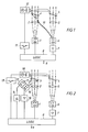
- Fig. 1 ein erstes Ausführungsbeispiel gemäß der Erfindung angewendet bei einem Meßgerät zur Messung der Wolkenhöhe oder der Sichtweite,
- Fig. 2 ein zweites Ausführungsbeispiel einer Anordnung gemäß der Erfindung angewendet bei einem gleichen Meßgerät wie in Fig. 1.
- 1 shows a first embodiment according to the invention applied to a measuring device for measuring cloud height or visibility,
- FIG. 2 shows a second exemplary embodiment of an arrangement according to the invention applied to the same measuring device as in FIG. 1.
Das in den Figuren 1 und 2 gleichermaßen dargestellte Meßgerät zur Messung der Wolkenhöhe, der Sichtweite oder eines Abstandes umfaßt die Teile 1 bis 9. Das Meßgerät arbeitet nach dem Prinzip des optischen Radars. Zum Senderteil gehören der Sender 1, die Sendeoptik 2 und das Senderfenster 3. Zum Empfängerteil gehören das Empfängerfenster 4, die Empfängeroptik 5, der Empfänger 6 und der Signaldetektor 7. Der Prozessor 8 enthält die elektronische Ausrüstung, die unter anderem den Lasersender aktiviert und den Meßverlauf steuert, die Impulse zählt und Daten 9 zu schreibenden und/oder anzeigenden Geräten überträgt.The measuring device shown equally in FIGS. 1 and 2 for measuring the cloud height, visibility or a distance comprises parts 1 to 9. The measuring device works on the principle of optical radar. The transmitter part includes the transmitter 1, the
Zu der Reinigungsanordnung gemäß der Erfindung gehören in Fig. 1 ein Lichtleiter 10 und ein Speiseglied 11 für die Reinigungsvorrichtung 12. Im übrigen bedient sich die Reinigungsanordnung der im Meßgerät bereits vorhandenen Sende- und Empfängereinheiten.In FIG. 1, the cleaning arrangement according to the invention includes a
Die Reinigungsanordnung gemäß Figur 2 enthält einen eigenen Sender 13 mit Speiseglied 14 und einen eigenen Empfänger 15 mit Signaldetektor 16 sowie die Reinigungsvorrichtung 18 mit Speiseglied 17, über welches die Reinigungsvorrichtung eingeschaltet wird.The cleaning arrangement according to FIG. 2 contains its
Beide Ausführungsformen der Erfindung arbeiten nach dem gleichen Prinzip. Die auf der Außenseite des Senderfensters vorhandene Fremdschicht (Schmutz, Schnee, Regen) wird dadurch erfaßt, daß die von dieser Schicht reflektierte Strahlung gemessen wird. Da der räumliche Abstand zwischen Senderfenster und Empfängerfenster klein ist, kann davon ausgegangen werden, da3 die Fremdschicht auf beiden Fenstern gleich ist. Im Prinzip kann auch ein gemeinsames Fenster für den Sender und Empfänger vorhanden sein. Die von der Fremdschicht (z.B. Wassertropfen) auf der Außenseite des Fensters reflektierte Strahlung wird auf den Empfänger geleitet und steuert die Einschaltung des Reinigungsaggregats 12 bzw. 17.Both embodiments of the invention work on the same principle. The foreign layer (dirt, snow, rain) on the outside of the transmitter window is detected by measuring the radiation reflected by this layer. Since the spatial distance between the transmitter window and the receiver window is small, it can be assumed that the foreign layer is the same on both windows. In principle, there can also be a common window for the transmitter and receiver. The radiation reflected by the foreign layer (e.g. water drops) on the outside of the window is directed to the receiver and controls the activation of the
Bei der in Figur 1 gezeigten Ausführungsform werden Sender und Empfänger des Meßgerätes selbst genutzt, um eine eventuelle Fremdschicht zu erkennen. Das von der Außenseite des Senderfensters 3 reflektierte Licht wird gesammelt und über den Lichtleiter 10 direkt zum Empfänger 6 geleitet. Im Prozessor 8 ist für diese Reflexionsmessung eine besondere Meßfolge programmiert, und das entsprechende reflektierte Signal wird von dem Prozessor verarbeitet. Die Reflexionsmessung zur Erfassung der Fremdschicht wird vom Prozessor so gesteuert, daß sie entweder vor oder nach einer Wolkenhöhen- oder Sichtmessung erfolgt, um die letztere nicht zu stören. Der Wert des gemessenen reflektierten Lichtes wird im Prozessor 8 mit einem vorgegebenen Vergleichswert verglichen, der der maximal zulässigen Verschmutzung des Senderfensters entspricht. Wird der Vergleichswert überschritten, so geht vom Prozessor 8 ein Signal an das Speiseglied 11, welches die Reinigungsvorrichtung 12 in Gang setzt.In the embodiment shown in FIG. 1, the transmitter and receiver of the measuring device itself are used to detect a possible foreign layer. The light reflected from the outside of the
In der Ausführungsform nach Figur 2 gehört zur Reinigungsanordnung ein eigener Sender 13 mit einem eigenen Speiseglied 14 für die Beleuchtung des Senderfensters 3 sowie ein eigener Empfänge@Xit Detektor 16 zur Messung des vom Senderfenster reflektierten Lichtes. Der Prozessor 8 übernimmt in dieser Reinigungsanordnung die gleiche Funktion wie in Figur 1. Er steuert also den Sender 13 und Empfänger 15, wandelt das reflektierte Licht in einen Meßwert für den Verschmutzungsgrad des Fensters um, vergleicht diesen Wert mit einem vorgegebenen Vergleichswert, der der höchst zulässigen Verschmutzung entspricht, und aktiviert das Speiseglied 17 der Reinigungsvorrichtung 18, wenn der Meßwert den Vergleichswert überschreitet.In the embodiment according to FIG. 2, the cleaning arrangement has its
Bei den Reinigungsvorrichtungen 12 und 18 in Figur 1 bzw. Figur 2 handelt es sich um dieselbe Vorrichtung, die jedoch, wie bereits erwähnt, in verschiedener Weise ausgebildet sein kann. In ihrer einfachsten Form kann die Vorrichtung ein Hochdruckaggregat sein, welches erwärmte Luft an den Fenstern 3 und 4 entlangbläst. In Gebieten mit starker Luftverunreinigung, z.B. Industriegebieten, wo mit einer starken Verschmutzung der Fenstergläser zu rechnen ist, kann zur Erzielung einer besseren Reinigungswirkung eine ergänzte Reinigungsvorrichtung verwendet werden. Die Ergänzung kann aus einem hin- und herschwingenden oder rotierenden Wischerblatt mit weicher Anlagekante an der Außenseite des Senderfensters bestehen. Wegen der hierbei auftretenden Kratzgefahr ist es zweckmäßig, den weichen Teil des Wischerblattes durch einen Trockenarm zu ersetzen, der einen auf das Glas gerichteten offenen Spalt oder eine Lochreihe hat, durch den/die Druckluft oder Spülflüssigkeit zugeführt wird, so daß sich ein Film aus Druckluft oder Flüssigkeit zwischen dem Fensterglas und dem nahe über dem Glas sich bewegenden Trockenarm ausbildet. Der Reinigungsvorgang kann beispielsweise in der Art programmiert werden, daß zunächst ein Spülen und anschließend ein Trocknen durch das Beblasen mit erwärmter Druckluft stattfindet.The
Bei beiden Ausführungsformen wird die Reinigungsvorrichtung automatisch stillgesetzt, nachdem das Fenster gereinigt worden ist, d.h., sobald kein oder-nur eine geringe Menge von Licht an der Außenseite des Fensters reflektiert wird.In both embodiments, the cleaning device is automatically stopped after the window has been cleaned, i.e. as soon as no or only a small amount of light is reflected on the outside of the window.
Eine Anordnung nach der Erfindung ist nicht auf die gezeigten beiden Ausführungsformen beschränkt, sondern kann im Rahmen des offenbarten Erfindungsgedankens in vielfacher Weise variiert werden.An arrangement according to the invention is not limited to the two embodiments shown, but can be varied in many ways within the scope of the disclosed inventive concept.
Die Messung kann natürlich sowohl am Sender- und Empfängerfenster vorgenommen werden oder nur an einem der Fenster. Wird die Messung am Empfängerfenster durchgeführt, so wird bei der Ausführung nach Figur 1 ein Lichtleiter verwendet, der Licht vom Sender zur Beleuchtung des Empfängerfensters überträgt. Die Ausführungsform gemäß Figur 2 kann für das Empfängerfenster in gleicher Weise wie für das Senderfenster verwendet werden. Es kann auch nur mit einem separaten Sender 13 und beispielsweise dem eigenen Empfänger 6 des Wolkenhöhenmeßgerätes gearbeitet werden, wobei der Empfänger 6 die durch die Femdschicht auf dem Fensterglas bedingten Reflexionen auffängt. Wenn störende Reflexionen von der Fremdschichtmessung auf dem Glas auftreten können oder wenn das Wolkenhöhenmeßsystem des Wolkenhöhenmeßgeräts benutzt wird, muß das Messen der Fensterfremdschicht auf solche Weise vorgenommen werden, daß die Wolkenhöhen- oder Sichtmessung nicht gestört wird.The measurement can of course be carried out on the transmitter and receiver window or only on one of the windows. If the measurement is carried out on the receiver window, a light guide is used in the embodiment according to FIG. 1, which transmits light from the transmitter for illuminating the receiver window. The embodiment according to FIG. 2 can be used for the receiver window in the same way as for the transmitter window. It is also possible to work only with a
Claims (10)
Applications Claiming Priority (2)
| Application Number | Priority Date | Filing Date | Title |
|---|---|---|---|
| SE8206819 | 1982-11-30 | ||
| SE8206819A SE453539B (en) | 1982-11-30 | 1982-11-30 | DEVICE FOR CLEANING WINDOWS FOR CLOUD HEIGHT AND VIEW METERS |
Publications (3)
| Publication Number | Publication Date |
|---|---|
| EP0112498A2 true EP0112498A2 (en) | 1984-07-04 |
| EP0112498A3 EP0112498A3 (en) | 1986-12-17 |
| EP0112498B1 EP0112498B1 (en) | 1989-02-01 |
Family
ID=20348799
Family Applications (1)
| Application Number | Title | Priority Date | Filing Date |
|---|---|---|---|
| EP19830111698 Expired EP0112498B1 (en) | 1982-11-30 | 1983-11-23 | Apparatus for automatically cleaning windows |
Country Status (4)
| Country | Link |
|---|---|
| EP (1) | EP0112498B1 (en) |
| JP (1) | JPS59109878A (en) |
| DE (1) | DE3379098D1 (en) |
| SE (1) | SE453539B (en) |
Cited By (51)
| Publication number | Priority date | Publication date | Assignee | Title |
|---|---|---|---|---|
| DE19615333A1 (en) * | 1995-07-24 | 1997-01-30 | Hewlett Packard Co | Gas analyser partic. for human breath - incorporates an in-situ system using carbon di:oxide snow for cleaning optical surfaces and thus allowing the analysis chamber to remain closed |
| DE29621783U1 (en) * | 1996-12-16 | 1998-04-16 | Hohe Gmbh & Co Kg | Glass cleaning device, in particular for vehicles |
| WO1998035221A1 (en) * | 1997-02-08 | 1998-08-13 | Temic Telefunken Microelectronic Gmbh | Optical transmitting and receiving device |
| DE19912971C1 (en) * | 1999-03-23 | 2000-09-21 | Daimler Chrysler Ag | Method for detecting the light output of a transmission diode of an optical monitoring unit and suitable circuit arrangement |
| GB2426577A (en) * | 2005-05-27 | 2006-11-29 | Thorn Security | An optical detector with a reflector outside of its housing, and a plurality of sensors inside of its housing |
| US7875047B2 (en) | 2002-04-19 | 2011-01-25 | Pelikan Technologies, Inc. | Method and apparatus for a multi-use body fluid sampling device with sterility barrier release |
| US7901365B2 (en) | 2002-04-19 | 2011-03-08 | Pelikan Technologies, Inc. | Method and apparatus for penetrating tissue |
| US7909775B2 (en) | 2001-06-12 | 2011-03-22 | Pelikan Technologies, Inc. | Method and apparatus for lancet launching device integrated onto a blood-sampling cartridge |
| US7909774B2 (en) | 2002-04-19 | 2011-03-22 | Pelikan Technologies, Inc. | Method and apparatus for penetrating tissue |
| US7909777B2 (en) | 2002-04-19 | 2011-03-22 | Pelikan Technologies, Inc | Method and apparatus for penetrating tissue |
| US7909778B2 (en) | 2002-04-19 | 2011-03-22 | Pelikan Technologies, Inc. | Method and apparatus for penetrating tissue |
| US7914465B2 (en) | 2002-04-19 | 2011-03-29 | Pelikan Technologies, Inc. | Method and apparatus for penetrating tissue |
| US7976476B2 (en) | 2002-04-19 | 2011-07-12 | Pelikan Technologies, Inc. | Device and method for variable speed lancet |
| US7981055B2 (en) | 2001-06-12 | 2011-07-19 | Pelikan Technologies, Inc. | Tissue penetration device |
| US7981056B2 (en) | 2002-04-19 | 2011-07-19 | Pelikan Technologies, Inc. | Methods and apparatus for lancet actuation |
| US7988645B2 (en) | 2001-06-12 | 2011-08-02 | Pelikan Technologies, Inc. | Self optimizing lancing device with adaptation means to temporal variations in cutaneous properties |
| US8007446B2 (en) | 2002-04-19 | 2011-08-30 | Pelikan Technologies, Inc. | Method and apparatus for penetrating tissue |
| US8062231B2 (en) | 2002-04-19 | 2011-11-22 | Pelikan Technologies, Inc. | Method and apparatus for penetrating tissue |
| US8079960B2 (en) | 2002-04-19 | 2011-12-20 | Pelikan Technologies, Inc. | Methods and apparatus for lancet actuation |
| US8221334B2 (en) | 2002-04-19 | 2012-07-17 | Sanofi-Aventis Deutschland Gmbh | Method and apparatus for penetrating tissue |
| US8251921B2 (en) | 2003-06-06 | 2012-08-28 | Sanofi-Aventis Deutschland Gmbh | Method and apparatus for body fluid sampling and analyte sensing |
| US8262614B2 (en) | 2003-05-30 | 2012-09-11 | Pelikan Technologies, Inc. | Method and apparatus for fluid injection |
| US8267870B2 (en) | 2002-04-19 | 2012-09-18 | Sanofi-Aventis Deutschland Gmbh | Method and apparatus for body fluid sampling with hybrid actuation |
| US8296918B2 (en) | 2003-12-31 | 2012-10-30 | Sanofi-Aventis Deutschland Gmbh | Method of manufacturing a fluid sampling device with improved analyte detecting member configuration |
| US8333710B2 (en) | 2002-04-19 | 2012-12-18 | Sanofi-Aventis Deutschland Gmbh | Tissue penetration device |
| US8360992B2 (en) | 2002-04-19 | 2013-01-29 | Sanofi-Aventis Deutschland Gmbh | Method and apparatus for penetrating tissue |
| US8382682B2 (en) | 2002-04-19 | 2013-02-26 | Sanofi-Aventis Deutschland Gmbh | Method and apparatus for penetrating tissue |
| US8435190B2 (en) | 2002-04-19 | 2013-05-07 | Sanofi-Aventis Deutschland Gmbh | Method and apparatus for penetrating tissue |
| US8439872B2 (en) | 1998-03-30 | 2013-05-14 | Sanofi-Aventis Deutschland Gmbh | Apparatus and method for penetration with shaft having a sensor for sensing penetration depth |
| US8556829B2 (en) | 2002-04-19 | 2013-10-15 | Sanofi-Aventis Deutschland Gmbh | Method and apparatus for penetrating tissue |
| US8574895B2 (en) | 2002-12-30 | 2013-11-05 | Sanofi-Aventis Deutschland Gmbh | Method and apparatus using optical techniques to measure analyte levels |
| US8579831B2 (en) | 2002-04-19 | 2013-11-12 | Sanofi-Aventis Deutschland Gmbh | Method and apparatus for penetrating tissue |
| US8641644B2 (en) | 2000-11-21 | 2014-02-04 | Sanofi-Aventis Deutschland Gmbh | Blood testing apparatus having a rotatable cartridge with multiple lancing elements and testing means |
| US8668656B2 (en) | 2003-12-31 | 2014-03-11 | Sanofi-Aventis Deutschland Gmbh | Method and apparatus for improving fluidic flow and sample capture |
| US8702624B2 (en) | 2006-09-29 | 2014-04-22 | Sanofi-Aventis Deutschland Gmbh | Analyte measurement device with a single shot actuator |
| US8721671B2 (en) | 2001-06-12 | 2014-05-13 | Sanofi-Aventis Deutschland Gmbh | Electric lancet actuator |
| US8784335B2 (en) | 2002-04-19 | 2014-07-22 | Sanofi-Aventis Deutschland Gmbh | Body fluid sampling device with a capacitive sensor |
| US8828203B2 (en) | 2004-05-20 | 2014-09-09 | Sanofi-Aventis Deutschland Gmbh | Printable hydrogels for biosensors |
| US8945910B2 (en) | 2003-09-29 | 2015-02-03 | Sanofi-Aventis Deutschland Gmbh | Method and apparatus for an improved sample capture device |
| US8965476B2 (en) | 2010-04-16 | 2015-02-24 | Sanofi-Aventis Deutschland Gmbh | Tissue penetration device |
| US9144401B2 (en) | 2003-06-11 | 2015-09-29 | Sanofi-Aventis Deutschland Gmbh | Low pain penetrating member |
| US9226699B2 (en) | 2002-04-19 | 2016-01-05 | Sanofi-Aventis Deutschland Gmbh | Body fluid sampling module with a continuous compression tissue interface surface |
| US9248267B2 (en) | 2002-04-19 | 2016-02-02 | Sanofi-Aventis Deustchland Gmbh | Tissue penetration device |
| US9314194B2 (en) | 2002-04-19 | 2016-04-19 | Sanofi-Aventis Deutschland Gmbh | Tissue penetration device |
| US9351680B2 (en) | 2003-10-14 | 2016-05-31 | Sanofi-Aventis Deutschland Gmbh | Method and apparatus for a variable user interface |
| US9375169B2 (en) | 2009-01-30 | 2016-06-28 | Sanofi-Aventis Deutschland Gmbh | Cam drive for managing disposable penetrating member actions with a single motor and motor and control system |
| US9386944B2 (en) | 2008-04-11 | 2016-07-12 | Sanofi-Aventis Deutschland Gmbh | Method and apparatus for analyte detecting device |
| US9427532B2 (en) | 2001-06-12 | 2016-08-30 | Sanofi-Aventis Deutschland Gmbh | Tissue penetration device |
| US9775553B2 (en) | 2004-06-03 | 2017-10-03 | Sanofi-Aventis Deutschland Gmbh | Method and apparatus for a fluid sampling device |
| US9795747B2 (en) | 2010-06-02 | 2017-10-24 | Sanofi-Aventis Deutschland Gmbh | Methods and apparatus for lancet actuation |
| US9820684B2 (en) | 2004-06-03 | 2017-11-21 | Sanofi-Aventis Deutschland Gmbh | Method and apparatus for a fluid sampling device |
Families Citing this family (2)
| Publication number | Priority date | Publication date | Assignee | Title |
|---|---|---|---|---|
| JP2579554Y2 (en) * | 1991-03-11 | 1998-08-27 | 富士通テン株式会社 | Inter-vehicle distance measuring device |
| GB2426578A (en) | 2005-05-27 | 2006-11-29 | Thorn Security | A flame detector having a pulsing optical test source that simulates the frequency of a flame |
Citations (4)
| Publication number | Priority date | Publication date | Assignee | Title |
|---|---|---|---|---|
| DE2346582A1 (en) * | 1973-09-15 | 1975-03-27 | Fraunhofer Ges Forschung | Window-cleaning robot controlled by mini-computer - has mechanical cleaning mechanism and position monitoring mechanism defining range of movement |
| JPS55141641A (en) * | 1979-04-23 | 1980-11-05 | Satake Eng Co Ltd | Dustproof device of particle color screening device |
| JPS55141657A (en) * | 1979-04-23 | 1980-11-05 | Nippon Kokan Kk <Nkk> | Surface inspecting apparatus |
| EP0061883A1 (en) * | 1981-03-26 | 1982-10-06 | Satake Engineering Co., Ltd. | Device for cleaning transparent plates of detecting sections of color sorting apparatus |
-
1982
- 1982-11-30 SE SE8206819A patent/SE453539B/en unknown
-
1983
- 1983-11-23 DE DE8383111698T patent/DE3379098D1/en not_active Expired
- 1983-11-23 EP EP19830111698 patent/EP0112498B1/en not_active Expired
- 1983-11-28 JP JP22400983A patent/JPS59109878A/en active Pending
Patent Citations (4)
| Publication number | Priority date | Publication date | Assignee | Title |
|---|---|---|---|---|
| DE2346582A1 (en) * | 1973-09-15 | 1975-03-27 | Fraunhofer Ges Forschung | Window-cleaning robot controlled by mini-computer - has mechanical cleaning mechanism and position monitoring mechanism defining range of movement |
| JPS55141641A (en) * | 1979-04-23 | 1980-11-05 | Satake Eng Co Ltd | Dustproof device of particle color screening device |
| JPS55141657A (en) * | 1979-04-23 | 1980-11-05 | Nippon Kokan Kk <Nkk> | Surface inspecting apparatus |
| EP0061883A1 (en) * | 1981-03-26 | 1982-10-06 | Satake Engineering Co., Ltd. | Device for cleaning transparent plates of detecting sections of color sorting apparatus |
Non-Patent Citations (2)
| Title |
|---|
| PATENT ABSTRACTS OF JAPAN, unexamined applications, Field P, Band 5, Nr. 13, 27 Janner 1981 THE PATENT OFFICE JAPANESE GOVERNMENT Seite 10 p 46 & JP-A-55 141 657 (NIPPON) * |
| PATENT ABSTRACTS OF JAPAN, unexamined applications, Field P, Band 5, Nr. 13, 27 Janner 1981 THE PATENT OFFICE JAPANESE GOVERNMENT Seite 6 P 46 & JP-A-55 141 641 (SATAKE) * |
Cited By (113)
| Publication number | Priority date | Publication date | Assignee | Title |
|---|---|---|---|---|
| DE19615333A1 (en) * | 1995-07-24 | 1997-01-30 | Hewlett Packard Co | Gas analyser partic. for human breath - incorporates an in-situ system using carbon di:oxide snow for cleaning optical surfaces and thus allowing the analysis chamber to remain closed |
| US5720650A (en) * | 1995-07-24 | 1998-02-24 | Hewlett-Packard Company | Gas analyzer with arrangement for spray-cleaning optical element |
| DE29621783U1 (en) * | 1996-12-16 | 1998-04-16 | Hohe Gmbh & Co Kg | Glass cleaning device, in particular for vehicles |
| EP1422513A2 (en) * | 1997-02-08 | 2004-05-26 | Conti Temic microelectronic GmbH | Optical transmitting and receiving device |
| US6624418B1 (en) | 1997-02-08 | 2003-09-23 | Conti Temic Microelectronic Gmbh | Optical transmitting and receiving device |
| EP1422513A3 (en) * | 1997-02-08 | 2006-05-24 | Conti Temic microelectronic GmbH | Optical transmitting and receiving device |
| WO1998035221A1 (en) * | 1997-02-08 | 1998-08-13 | Temic Telefunken Microelectronic Gmbh | Optical transmitting and receiving device |
| US8439872B2 (en) | 1998-03-30 | 2013-05-14 | Sanofi-Aventis Deutschland Gmbh | Apparatus and method for penetration with shaft having a sensor for sensing penetration depth |
| DE19912971C1 (en) * | 1999-03-23 | 2000-09-21 | Daimler Chrysler Ag | Method for detecting the light output of a transmission diode of an optical monitoring unit and suitable circuit arrangement |
| EP1039279A2 (en) * | 1999-03-23 | 2000-09-27 | DaimlerChrysler AG | Method for assessing the optical power of an emitting diode in a monitoring unit and suitable circuitry |
| EP1039279A3 (en) * | 1999-03-23 | 2001-03-21 | DaimlerChrysler AG | Method for assessing the optical power of an emitting diode in a monitoring unit and suitable circuitry |
| US6486945B1 (en) | 1999-03-23 | 2002-11-26 | Daimlerchrysler Ag | Method and circuit arrangement for measuring the light output of an emitter diode of an optical monitoring unit |
| US8641644B2 (en) | 2000-11-21 | 2014-02-04 | Sanofi-Aventis Deutschland Gmbh | Blood testing apparatus having a rotatable cartridge with multiple lancing elements and testing means |
| US8721671B2 (en) | 2001-06-12 | 2014-05-13 | Sanofi-Aventis Deutschland Gmbh | Electric lancet actuator |
| US9937298B2 (en) | 2001-06-12 | 2018-04-10 | Sanofi-Aventis Deutschland Gmbh | Tissue penetration device |
| US8211037B2 (en) | 2001-06-12 | 2012-07-03 | Pelikan Technologies, Inc. | Tissue penetration device |
| US9427532B2 (en) | 2001-06-12 | 2016-08-30 | Sanofi-Aventis Deutschland Gmbh | Tissue penetration device |
| US8845550B2 (en) | 2001-06-12 | 2014-09-30 | Sanofi-Aventis Deutschland Gmbh | Tissue penetration device |
| US8216154B2 (en) | 2001-06-12 | 2012-07-10 | Sanofi-Aventis Deutschland Gmbh | Tissue penetration device |
| US8679033B2 (en) | 2001-06-12 | 2014-03-25 | Sanofi-Aventis Deutschland Gmbh | Tissue penetration device |
| US9694144B2 (en) | 2001-06-12 | 2017-07-04 | Sanofi-Aventis Deutschland Gmbh | Sampling module device and method |
| US8641643B2 (en) | 2001-06-12 | 2014-02-04 | Sanofi-Aventis Deutschland Gmbh | Sampling module device and method |
| US7981055B2 (en) | 2001-06-12 | 2011-07-19 | Pelikan Technologies, Inc. | Tissue penetration device |
| US8622930B2 (en) | 2001-06-12 | 2014-01-07 | Sanofi-Aventis Deutschland Gmbh | Tissue penetration device |
| US9802007B2 (en) | 2001-06-12 | 2017-10-31 | Sanofi-Aventis Deutschland Gmbh | Methods and apparatus for lancet actuation |
| US7988645B2 (en) | 2001-06-12 | 2011-08-02 | Pelikan Technologies, Inc. | Self optimizing lancing device with adaptation means to temporal variations in cutaneous properties |
| US7909775B2 (en) | 2001-06-12 | 2011-03-22 | Pelikan Technologies, Inc. | Method and apparatus for lancet launching device integrated onto a blood-sampling cartridge |
| US8016774B2 (en) | 2001-06-12 | 2011-09-13 | Pelikan Technologies, Inc. | Tissue penetration device |
| US8382683B2 (en) | 2001-06-12 | 2013-02-26 | Sanofi-Aventis Deutschland Gmbh | Tissue penetration device |
| US8360991B2 (en) | 2001-06-12 | 2013-01-29 | Sanofi-Aventis Deutschland Gmbh | Tissue penetration device |
| US8123700B2 (en) | 2001-06-12 | 2012-02-28 | Pelikan Technologies, Inc. | Method and apparatus for lancet launching device integrated onto a blood-sampling cartridge |
| US8343075B2 (en) | 2001-06-12 | 2013-01-01 | Sanofi-Aventis Deutschland Gmbh | Tissue penetration device |
| US8162853B2 (en) | 2001-06-12 | 2012-04-24 | Pelikan Technologies, Inc. | Tissue penetration device |
| US8337421B2 (en) | 2001-06-12 | 2012-12-25 | Sanofi-Aventis Deutschland Gmbh | Tissue penetration device |
| US8282577B2 (en) | 2001-06-12 | 2012-10-09 | Sanofi-Aventis Deutschland Gmbh | Method and apparatus for lancet launching device integrated onto a blood-sampling cartridge |
| US8206317B2 (en) | 2001-06-12 | 2012-06-26 | Sanofi-Aventis Deutschland Gmbh | Tissue penetration device |
| US8206319B2 (en) | 2001-06-12 | 2012-06-26 | Sanofi-Aventis Deutschland Gmbh | Tissue penetration device |
| US9560993B2 (en) | 2001-11-21 | 2017-02-07 | Sanofi-Aventis Deutschland Gmbh | Blood testing apparatus having a rotatable cartridge with multiple lancing elements and testing means |
| US8414503B2 (en) | 2002-04-19 | 2013-04-09 | Sanofi-Aventis Deutschland Gmbh | Methods and apparatus for lancet actuation |
| US8784335B2 (en) | 2002-04-19 | 2014-07-22 | Sanofi-Aventis Deutschland Gmbh | Body fluid sampling device with a capacitive sensor |
| US9907502B2 (en) | 2002-04-19 | 2018-03-06 | Sanofi-Aventis Deutschland Gmbh | Method and apparatus for penetrating tissue |
| US9839386B2 (en) | 2002-04-19 | 2017-12-12 | Sanofi-Aventis Deustschland Gmbh | Body fluid sampling device with capacitive sensor |
| US8267870B2 (en) | 2002-04-19 | 2012-09-18 | Sanofi-Aventis Deutschland Gmbh | Method and apparatus for body fluid sampling with hybrid actuation |
| US8202231B2 (en) | 2002-04-19 | 2012-06-19 | Sanofi-Aventis Deutschland Gmbh | Method and apparatus for penetrating tissue |
| US7875047B2 (en) | 2002-04-19 | 2011-01-25 | Pelikan Technologies, Inc. | Method and apparatus for a multi-use body fluid sampling device with sterility barrier release |
| US8333710B2 (en) | 2002-04-19 | 2012-12-18 | Sanofi-Aventis Deutschland Gmbh | Tissue penetration device |
| US8197423B2 (en) | 2002-04-19 | 2012-06-12 | Pelikan Technologies, Inc. | Method and apparatus for penetrating tissue |
| US8337420B2 (en) | 2002-04-19 | 2012-12-25 | Sanofi-Aventis Deutschland Gmbh | Tissue penetration device |
| US8337419B2 (en) | 2002-04-19 | 2012-12-25 | Sanofi-Aventis Deutschland Gmbh | Tissue penetration device |
| US8157748B2 (en) | 2002-04-19 | 2012-04-17 | Pelikan Technologies, Inc. | Methods and apparatus for lancet actuation |
| US8360992B2 (en) | 2002-04-19 | 2013-01-29 | Sanofi-Aventis Deutschland Gmbh | Method and apparatus for penetrating tissue |
| US8079960B2 (en) | 2002-04-19 | 2011-12-20 | Pelikan Technologies, Inc. | Methods and apparatus for lancet actuation |
| US8062231B2 (en) | 2002-04-19 | 2011-11-22 | Pelikan Technologies, Inc. | Method and apparatus for penetrating tissue |
| US8382682B2 (en) | 2002-04-19 | 2013-02-26 | Sanofi-Aventis Deutschland Gmbh | Method and apparatus for penetrating tissue |
| US8388551B2 (en) | 2002-04-19 | 2013-03-05 | Sanofi-Aventis Deutschland Gmbh | Method and apparatus for multi-use body fluid sampling device with sterility barrier release |
| US8403864B2 (en) | 2002-04-19 | 2013-03-26 | Sanofi-Aventis Deutschland Gmbh | Method and apparatus for penetrating tissue |
| US8007446B2 (en) | 2002-04-19 | 2011-08-30 | Pelikan Technologies, Inc. | Method and apparatus for penetrating tissue |
| US8430828B2 (en) | 2002-04-19 | 2013-04-30 | Sanofi-Aventis Deutschland Gmbh | Method and apparatus for a multi-use body fluid sampling device with sterility barrier release |
| US8435190B2 (en) | 2002-04-19 | 2013-05-07 | Sanofi-Aventis Deutschland Gmbh | Method and apparatus for penetrating tissue |
| US7988644B2 (en) | 2002-04-19 | 2011-08-02 | Pelikan Technologies, Inc. | Method and apparatus for a multi-use body fluid sampling device with sterility barrier release |
| US8491500B2 (en) | 2002-04-19 | 2013-07-23 | Sanofi-Aventis Deutschland Gmbh | Methods and apparatus for lancet actuation |
| US8496601B2 (en) | 2002-04-19 | 2013-07-30 | Sanofi-Aventis Deutschland Gmbh | Methods and apparatus for lancet actuation |
| US8556829B2 (en) | 2002-04-19 | 2013-10-15 | Sanofi-Aventis Deutschland Gmbh | Method and apparatus for penetrating tissue |
| US8562545B2 (en) | 2002-04-19 | 2013-10-22 | Sanofi-Aventis Deutschland Gmbh | Tissue penetration device |
| US9795334B2 (en) | 2002-04-19 | 2017-10-24 | Sanofi-Aventis Deutschland Gmbh | Method and apparatus for penetrating tissue |
| US8574168B2 (en) | 2002-04-19 | 2013-11-05 | Sanofi-Aventis Deutschland Gmbh | Method and apparatus for a multi-use body fluid sampling device with analyte sensing |
| US8579831B2 (en) | 2002-04-19 | 2013-11-12 | Sanofi-Aventis Deutschland Gmbh | Method and apparatus for penetrating tissue |
| US7981056B2 (en) | 2002-04-19 | 2011-07-19 | Pelikan Technologies, Inc. | Methods and apparatus for lancet actuation |
| US8636673B2 (en) | 2002-04-19 | 2014-01-28 | Sanofi-Aventis Deutschland Gmbh | Tissue penetration device |
| US7976476B2 (en) | 2002-04-19 | 2011-07-12 | Pelikan Technologies, Inc. | Device and method for variable speed lancet |
| US7959582B2 (en) | 2002-04-19 | 2011-06-14 | Pelikan Technologies, Inc. | Method and apparatus for penetrating tissue |
| US9724021B2 (en) | 2002-04-19 | 2017-08-08 | Sanofi-Aventis Deutschland Gmbh | Method and apparatus for penetrating tissue |
| US7938787B2 (en) | 2002-04-19 | 2011-05-10 | Pelikan Technologies, Inc. | Method and apparatus for penetrating tissue |
| US8690796B2 (en) | 2002-04-19 | 2014-04-08 | Sanofi-Aventis Deutschland Gmbh | Method and apparatus for penetrating tissue |
| US7901365B2 (en) | 2002-04-19 | 2011-03-08 | Pelikan Technologies, Inc. | Method and apparatus for penetrating tissue |
| US7914465B2 (en) | 2002-04-19 | 2011-03-29 | Pelikan Technologies, Inc. | Method and apparatus for penetrating tissue |
| US8221334B2 (en) | 2002-04-19 | 2012-07-17 | Sanofi-Aventis Deutschland Gmbh | Method and apparatus for penetrating tissue |
| US8808201B2 (en) | 2002-04-19 | 2014-08-19 | Sanofi-Aventis Deutschland Gmbh | Methods and apparatus for penetrating tissue |
| US7909774B2 (en) | 2002-04-19 | 2011-03-22 | Pelikan Technologies, Inc. | Method and apparatus for penetrating tissue |
| US7909778B2 (en) | 2002-04-19 | 2011-03-22 | Pelikan Technologies, Inc. | Method and apparatus for penetrating tissue |
| US8845549B2 (en) | 2002-04-19 | 2014-09-30 | Sanofi-Aventis Deutschland Gmbh | Method for penetrating tissue |
| US8905945B2 (en) | 2002-04-19 | 2014-12-09 | Dominique M. Freeman | Method and apparatus for penetrating tissue |
| US9498160B2 (en) | 2002-04-19 | 2016-11-22 | Sanofi-Aventis Deutschland Gmbh | Method for penetrating tissue |
| US7909777B2 (en) | 2002-04-19 | 2011-03-22 | Pelikan Technologies, Inc | Method and apparatus for penetrating tissue |
| US9339612B2 (en) | 2002-04-19 | 2016-05-17 | Sanofi-Aventis Deutschland Gmbh | Tissue penetration device |
| US9072842B2 (en) | 2002-04-19 | 2015-07-07 | Sanofi-Aventis Deutschland Gmbh | Method and apparatus for penetrating tissue |
| US9089678B2 (en) | 2002-04-19 | 2015-07-28 | Sanofi-Aventis Deutschland Gmbh | Method and apparatus for penetrating tissue |
| US9089294B2 (en) | 2002-04-19 | 2015-07-28 | Sanofi-Aventis Deutschland Gmbh | Analyte measurement device with a single shot actuator |
| US9314194B2 (en) | 2002-04-19 | 2016-04-19 | Sanofi-Aventis Deutschland Gmbh | Tissue penetration device |
| US9186468B2 (en) | 2002-04-19 | 2015-11-17 | Sanofi-Aventis Deutschland Gmbh | Method and apparatus for penetrating tissue |
| US9226699B2 (en) | 2002-04-19 | 2016-01-05 | Sanofi-Aventis Deutschland Gmbh | Body fluid sampling module with a continuous compression tissue interface surface |
| US9248267B2 (en) | 2002-04-19 | 2016-02-02 | Sanofi-Aventis Deustchland Gmbh | Tissue penetration device |
| US9034639B2 (en) | 2002-12-30 | 2015-05-19 | Sanofi-Aventis Deutschland Gmbh | Method and apparatus using optical techniques to measure analyte levels |
| US8574895B2 (en) | 2002-12-30 | 2013-11-05 | Sanofi-Aventis Deutschland Gmbh | Method and apparatus using optical techniques to measure analyte levels |
| US8262614B2 (en) | 2003-05-30 | 2012-09-11 | Pelikan Technologies, Inc. | Method and apparatus for fluid injection |
| US8251921B2 (en) | 2003-06-06 | 2012-08-28 | Sanofi-Aventis Deutschland Gmbh | Method and apparatus for body fluid sampling and analyte sensing |
| US9144401B2 (en) | 2003-06-11 | 2015-09-29 | Sanofi-Aventis Deutschland Gmbh | Low pain penetrating member |
| US10034628B2 (en) | 2003-06-11 | 2018-07-31 | Sanofi-Aventis Deutschland Gmbh | Low pain penetrating member |
| US8945910B2 (en) | 2003-09-29 | 2015-02-03 | Sanofi-Aventis Deutschland Gmbh | Method and apparatus for an improved sample capture device |
| US9351680B2 (en) | 2003-10-14 | 2016-05-31 | Sanofi-Aventis Deutschland Gmbh | Method and apparatus for a variable user interface |
| US9561000B2 (en) | 2003-12-31 | 2017-02-07 | Sanofi-Aventis Deutschland Gmbh | Method and apparatus for improving fluidic flow and sample capture |
| US8668656B2 (en) | 2003-12-31 | 2014-03-11 | Sanofi-Aventis Deutschland Gmbh | Method and apparatus for improving fluidic flow and sample capture |
| US8296918B2 (en) | 2003-12-31 | 2012-10-30 | Sanofi-Aventis Deutschland Gmbh | Method of manufacturing a fluid sampling device with improved analyte detecting member configuration |
| US8828203B2 (en) | 2004-05-20 | 2014-09-09 | Sanofi-Aventis Deutschland Gmbh | Printable hydrogels for biosensors |
| US9261476B2 (en) | 2004-05-20 | 2016-02-16 | Sanofi Sa | Printable hydrogel for biosensors |
| US9775553B2 (en) | 2004-06-03 | 2017-10-03 | Sanofi-Aventis Deutschland Gmbh | Method and apparatus for a fluid sampling device |
| US9820684B2 (en) | 2004-06-03 | 2017-11-21 | Sanofi-Aventis Deutschland Gmbh | Method and apparatus for a fluid sampling device |
| GB2426577A (en) * | 2005-05-27 | 2006-11-29 | Thorn Security | An optical detector with a reflector outside of its housing, and a plurality of sensors inside of its housing |
| US8702624B2 (en) | 2006-09-29 | 2014-04-22 | Sanofi-Aventis Deutschland Gmbh | Analyte measurement device with a single shot actuator |
| US9386944B2 (en) | 2008-04-11 | 2016-07-12 | Sanofi-Aventis Deutschland Gmbh | Method and apparatus for analyte detecting device |
| US9375169B2 (en) | 2009-01-30 | 2016-06-28 | Sanofi-Aventis Deutschland Gmbh | Cam drive for managing disposable penetrating member actions with a single motor and motor and control system |
| US8965476B2 (en) | 2010-04-16 | 2015-02-24 | Sanofi-Aventis Deutschland Gmbh | Tissue penetration device |
| US9795747B2 (en) | 2010-06-02 | 2017-10-24 | Sanofi-Aventis Deutschland Gmbh | Methods and apparatus for lancet actuation |
Also Published As
| Publication number | Publication date |
|---|---|
| SE8206819D0 (en) | 1982-11-30 |
| EP0112498B1 (en) | 1989-02-01 |
| SE8206819L (en) | 1984-05-31 |
| EP0112498A3 (en) | 1986-12-17 |
| SE453539B (en) | 1988-02-18 |
| DE3379098D1 (en) | 1989-03-09 |
| JPS59109878A (en) | 1984-06-25 |
Similar Documents
| Publication | Publication Date | Title |
|---|---|---|
| EP0112498B1 (en) | Apparatus for automatically cleaning windows | |
| DE3515194C2 (en) | ||
| EP0344404B1 (en) | Method and device for controlling the position of an automatic door | |
| DE3735267C3 (en) | Visibility measurement device | |
| DE4340756C5 (en) | Laser range finding device | |
| EP1302784A2 (en) | Method for determining visibility | |
| DE3536659C2 (en) | ||
| DE3926228C2 (en) | ||
| EP0122609B1 (en) | Method and embodiment for controlling the transmitted energy of a cloud height measurement apparatus | |
| EP0958493B1 (en) | Optical transmitting and receiving device | |
| EP0264860A2 (en) | Obstacle detection device for a motor vehicle | |
| DE4345446C2 (en) | Laser range finder, e.g. for driverless transport system | |
| DE2844679A1 (en) | DEVICE FOR INSPECTING THE SIDE WALLS OF BOTTLES | |
| DE2256736B2 (en) | Measuring arrangement for the automatic testing of the surface quality and evenness of a workpiece surface | |
| EP0152894B1 (en) | Device for optically detecting local inhomogeneities in the structure of tested objects | |
| DE3235590C2 (en) | Device for the optical detection of foreign bodies | |
| EP0063761A1 (en) | Method and device for testing areas limited by circular lines | |
| DE3602008C2 (en) | ||
| DE2717064C2 (en) | Measuring device for the optical measurement of a predetermined property of flowing granulate | |
| DE2833635C2 (en) | Method for measuring the contamination of optical interfaces in optical receivers and device for carrying out the method | |
| EP0211803A1 (en) | Apparatus with a telecentric F-theta lens for a contactless measuring system, and use of said apparatus | |
| DE4229491A1 (en) | Vehicular windscreen wiper controller with optical moisture detector - responds to encoded light pulse reflection in raindrops with increase in frequency of wiper motor operation | |
| DE3129808C2 (en) | Method for testing transparent material webs | |
| EP0402380A1 (en) | Process and device for testing transparent webs | |
| DE2154086C3 (en) | Device for photoelectrically scanning a continuously moving sheet of flat glass for automatic error detection |
Legal Events
| Date | Code | Title | Description |
|---|---|---|---|
| PUAI | Public reference made under article 153(3) epc to a published international application that has entered the european phase |
Free format text: ORIGINAL CODE: 0009012 |
|
| AK | Designated contracting states |
Designated state(s): DE FR GB |
|
| PUAL | Search report despatched |
Free format text: ORIGINAL CODE: 0009013 |
|
| AK | Designated contracting states |
Kind code of ref document: A3 Designated state(s): DE FR GB |
|
| 17P | Request for examination filed |
Effective date: 19870408 |
|
| 17Q | First examination report despatched |
Effective date: 19880125 |
|
| GRAA | (expected) grant |
Free format text: ORIGINAL CODE: 0009210 |
|
| AK | Designated contracting states |
Kind code of ref document: B1 Designated state(s): DE FR GB |
|
| REF | Corresponds to: |
Ref document number: 3379098 Country of ref document: DE Date of ref document: 19890309 |
|
| ET | Fr: translation filed | ||
| PLBE | No opposition filed within time limit |
Free format text: ORIGINAL CODE: 0009261 |
|
| STAA | Information on the status of an ep patent application or granted ep patent |
Free format text: STATUS: NO OPPOSITION FILED WITHIN TIME LIMIT |
|
| 26N | No opposition filed | ||
| PGFP | Annual fee paid to national office [announced via postgrant information from national office to epo] |
Ref country code: FR Payment date: 19941013 Year of fee payment: 12 |
|
| PGFP | Annual fee paid to national office [announced via postgrant information from national office to epo] |
Ref country code: GB Payment date: 19941026 Year of fee payment: 12 Ref country code: DE Payment date: 19941026 Year of fee payment: 12 |
|
| PG25 | Lapsed in a contracting state [announced via postgrant information from national office to epo] |
Ref country code: GB Effective date: 19951123 |
|
| GBPC | Gb: european patent ceased through non-payment of renewal fee |
Effective date: 19951123 |
|
| PG25 | Lapsed in a contracting state [announced via postgrant information from national office to epo] |
Ref country code: FR Effective date: 19960731 |
|
| PG25 | Lapsed in a contracting state [announced via postgrant information from national office to epo] |
Ref country code: DE Effective date: 19960801 |
|
| REG | Reference to a national code |
Ref country code: FR Ref legal event code: ST |