EP0112663A2 - Nuclear magnetic resonance methods and apparatus - Google Patents
Nuclear magnetic resonance methods and apparatus Download PDFInfo
- Publication number
- EP0112663A2 EP0112663A2 EP83307292A EP83307292A EP0112663A2 EP 0112663 A2 EP0112663 A2 EP 0112663A2 EP 83307292 A EP83307292 A EP 83307292A EP 83307292 A EP83307292 A EP 83307292A EP 0112663 A2 EP0112663 A2 EP 0112663A2
- Authority
- EP
- European Patent Office
- Prior art keywords
- gradient
- slices
- field
- nuclear magnetic
- magnetic resonance
- Prior art date
- Legal status (The legal status is an assumption and is not a legal conclusion. Google has not performed a legal analysis and makes no representation as to the accuracy of the status listed.)
- Granted
Links
Images

Classifications
-
- G—PHYSICS
- G01—MEASURING; TESTING
- G01R—MEASURING ELECTRIC VARIABLES; MEASURING MAGNETIC VARIABLES
- G01R33/00—Arrangements or instruments for measuring magnetic variables
- G01R33/20—Arrangements or instruments for measuring magnetic variables involving magnetic resonance
- G01R33/44—Arrangements or instruments for measuring magnetic variables involving magnetic resonance using nuclear magnetic resonance [NMR]
- G01R33/48—NMR imaging systems
- G01R33/483—NMR imaging systems with selection of signals or spectra from particular regions of the volume, e.g. in vivo spectroscopy
- G01R33/4833—NMR imaging systems with selection of signals or spectra from particular regions of the volume, e.g. in vivo spectroscopy using spatially selective excitation of the volume of interest, e.g. selecting non-orthogonal or inclined slices
- G01R33/4835—NMR imaging systems with selection of signals or spectra from particular regions of the volume, e.g. in vivo spectroscopy using spatially selective excitation of the volume of interest, e.g. selecting non-orthogonal or inclined slices of multiple slices
Definitions
- This invention relates to methods for obtaining a representation of the spatial distribution in a body of a quantity relating to nuclear magnetic resonance (NMR) and apparatus for use therein.
- NMR nuclear magnetic resonance
- NMR methods have been used for the chemical analysis of materials for many years. More recently NMR methods have been used to obtain images representing the distribution over a selected cross-sectional slice of a body of a chosen quantity, e.g. the density of chosen nuclei for example hydrogen nuclei, or of NMR spin relaxation time constants. The time taken to obtain such images is determined primarily by the NMR spin relaxation time constants, and can amount to an appreciable period, particularly if images of more than one slice are required.
- a method of obtaining a representation of the spatial distribution in a plurality of substantially parallel slices of a body of a quantity relating to nuclear magnetic rtsonance includes: applying a uniform magnetic field to said body; imposing a first gradient on said field in a chosen direction; applying a plurality of r.f.
- At least one further gradient parallel to the planes of said slices is imposed on said field so as to disperse the resonance within each of said slices.
- the invention also provides an apparatus arranged to obtain a representation of the spatial distribution in a plurality of substantially parallel slices of a body of a quantity relating to nuclear magnetic resonance including: means arranged to apply a uniform nagnetic field; means arranged to impose a first gradient on said field in a chosen direction; means arranged to apply a plurality of r.f. field pulses each within a different discrete frequency band; means arranged to remove said first magnetic field, and subsequently apply a second gradient on said field in said chosen direction, the direction of said second gradient being periodically reversed; means arranged to detect nuclear magnetic resonance signals occurring while said second gradient is imposed; and means arranged to process said signals to derive data relating to each of said plurality of slices.
- the method is performed using an apparatus similar to that described in U.K. Patent Specification No..1578910 or No.2056078, to which reference should be made for a fuller description, appropriately programmed to apply a sequence of magnetic field gradient and r.f. pulses and analyse the resulting signals as hereafter described.
- the first coil system comprises coils 1 capable of providing a steady uniform magnetic field in the Z direction; coils 3 capable of imposing a magnetic field gradient in the X direction, coils 5 capable of imposing a magnetic field gradient in the Y direction; and coils 7 capable of imposing a magnetic field gradient in the Z direction.
- the apparatus includes a second coil system 9 whereby r.f. magnetic fields can be applied to the body under examination in a plane normal to the direction of the steady uniform magnetic field produced by the first coil system, and whereby r.f. magnetic fields resulting from nuclei in the body under examination which have been excited to nuclear Magnetic resonance with a spin vector component other than in the Z direction can be detected.
- the various coils 1, 3, 5, 7 and 9 are driven by drive amplifiers 11, 12, 13, 15, 17 and 19 respectively, controlled by control circuits 21, 23 25 and 27 respectively.
- These circuits may take various forms which are well known to those with experience of NMR equipment and other apparatus using coil induced magnetic fields.
- the circuits 21, 23, 25 and 27 are controlled by a central processing and control unit 29 with which are associated inputs and other peripherals 31, for the provision of commands and instructions to the apparatus, and a display 33.
- the NMR signals detected by the coils 9 are applied via an amplifier 35 to a signal handling system 37.
- the signal handling system is arranged to make any appropriate calibration and correction of the signals, but essentially transmits the signals to the processing for application to the display to produce an image representing the distribution of an NMR quantity in the body being examined.
- the signal handling system 37 may conveniently form part of the unit 29.
- the apparatus also includes field measurement and error signal circuits 39 which receive signals via amplifiers 41 from field probes X 1 , X 2' Y 1 and Y 2 which are disposed at suitable positions in relation to the portion 43 of the body being examined, as illustrated in Figure 2, to monitor the applied magnetic fields.
- the R.F. control circuit 27 includes an arrangement shown schematically in Figure 3.
- This comprises a pulse generator 45 capable of simultaneously generating four r.f. pulses each having a limited bandwidth, e.g. of about 5 KHz, and each centred on a different one of four frequencies fl, f2, f3 and f4 such that the frequency bands of the pulses are discrete.
- the various outputs from the pulse generator 45 are combined in mixer 47, to produce a composite r.f. pulse which is fed via the r.f. drive amplifier 19 to the second coil system 9.
- Bo is applied by the first coil system to the body under examination in the Z direction.
- This field serves to define the equilibrium axis of magnetic alignment of nuclei in the body, i.e. along the Z direction, and remains constant throughout the examination procedure.
- An additional magnetic field Bz in the Z direction such as to impose a magnetic field gradient Gz in the Z direction is then applied by the coils 7, together with an r.f. magnetic field pulse B 1 produced by the arrangement shown in Figure 3.
- the magnetic field pulse B 1 is thus a composite pulse consisting of four component pulses having frequencies centred at fl, f2, f3 and f4.
- Each of these fre- queneies is chosen to be the Larmor frequency for hydrogen nuclei in a different one of four spaced parallel slices of the portion 43 of the body normal to the Z direction, S l , S 2 , S 3 and S 4 respectively, defined by four particular values of the magnetic field along the Z direction.
- the integral of the components of the pulse B 1 are chosen to be just sufficient to tip the spins of the excited nuclei into the X-Y plane, the spins then precessing in the X-Y plane round the Z axis.
- the gradient Gz is then removed and replaced by a gradient in the opposite sense - Gz.
- This causes the rephasing the spins within the four slices which have been selectively excited by the combination of the r.f. pulse B l , the steady uniform field Bo, and the gradient field Bz, the dephasing having been caused by the gradient through each of the slices S 1 , S 2 , S 3 , S 4 .
- the magnitude of -Gz is such that the spins are ally all rephased at the time at which this gradient is switched off as described, for example, in the above mentioned U.K. patent specification No. 1,578,910 the excited spins within the four slices then precessing at the same frequency within tbe same magnetic field.
- a further magnetic field in the Z direction is then applied by the coils 3, 5 such as to impose a gradient G R in direction orthogonal to the Z direction, this further filed being a composite of two fields respectively imposing gradients in the X and Y directions.
- a gradient G 2 z of substantially greater magnetude than G R is also imposed on the field along the Z direction, the direction of the gradient G 2 z being periodically reversed. The effect of the reversing of the gradient G 2 z is to generate a series of spin echoes after the initial free induction delay signal within each of the four chosen slices S 1 , S 2 , S 3 , S 4 .
- the effect of the G R gradient is to cause a frequecy dispersion of the resonance across each of the four slices in the direction of the G R gradient.
- the r.f. signals generated by the excited nuclei within the four slices are sampled, and the data thus derived is subjected to a Fourier Transformation process. Due to the fact that a periodic time dependence is introduced by the periodic reversal of the gradient G 2 z, a discreteness of the signals from along the Z direction is introduced.
- the Fourier Transformation process yields four spectra, one for each of the slices S 1 , S 2 , S 3 and S 4 , each centred on one of four different frequencies.
- Each spectra has a frequency distribution which contains information about the spatial distribution of frequency of the whole of each of the respective slices as projected onto the direction of G R within the slices.
- the r.f. and gradient filed sequence together with the processing sequence described herebefore is repceted for each of a large number of different orientations e.g. 180 within the X-Y plane.
- the images for the four slices are then obtained from the four sets of spatial distribution data for each orientation by a reconstruction technique such as the back projection processing technique.
- a method in accordance with the invention may alternatively use a two-dimensional Fourier Transformation technique to construct an image, such as described, for example, in J.Mag.Res.29, p.355-373 (1978), J.Mag.Res.18, p.69-83 (1975) and U.K. Patent Specification No. 2056078.
Abstract
Description
- This invention relates to methods for obtaining a representation of the spatial distribution in a body of a quantity relating to nuclear magnetic resonance (NMR) and apparatus for use therein.
- NMR methods have been used for the chemical analysis of materials for many years. More recently NMR methods have been used to obtain images representing the distribution over a selected cross-sectional slice of a body of a chosen quantity, e.g. the density of chosen nuclei for example hydrogen nuclei, or of NMR spin relaxation time constants. The time taken to obtain such images is determined primarily by the NMR spin relaxation time constants, and can amount to an appreciable period, particularly if images of more than one slice are required.
- It is an object of the present invention to provide a method of obtaining a representation of the spatial distribution of a quantity relating to NMR wherein this problem is alleviated by obtaining representations of several discrete slices of a body substantially simultaneously.
- According to the present invention a method of obtaining a representation of the spatial distribution in a plurality of substantially parallel slices of a body of a quantity relating to nuclear magnetic rtsonance includes: applying a uniform magnetic field to said body; imposing a first gradient on said field in a chosen direction; applying a plurality of r.f. field pulses each within a different discrete frequency band so as to excite nuclear magnetic resonance preferentially in a plurality of spaced parallel planar slices of said body whose planes lie perpendicular to said chosen direction; removing acid first gradient, and subsequently applying a second gradient on said field in said chosen direction, the direction of said second gradient being periodically reversed; detecting nuclear magnetic resonance signals occurring while said second gradient is imposed; and processing said signals to derive data relating to each of said plurality of slices.
- Preferably at least one further gradient parallel to the planes of said slices is imposed on said field so as to disperse the resonance within each of said slices.
- The invention also provides an apparatus arranged to obtain a representation of the spatial distribution in a plurality of substantially parallel slices of a body of a quantity relating to nuclear magnetic resonance including: means arranged to apply a uniform nagnetic field; means arranged to impose a first gradient on said field in a chosen direction; means arranged to apply a plurality of r.f. field pulses each within a different discrete frequency band; means arranged to remove said first magnetic field, and subsequently apply a second gradient on said field in said chosen direction, the direction of said second gradient being periodically reversed; means arranged to detect nuclear magnetic resonance signals occurring while said second gradient is imposed; and means arranged to process said signals to derive data relating to each of said plurality of slices.
- One method in accordance with the invention together with apparatus arranged to carry out this method will now be described, by way of example only, with reference to the accompanying drawings in which:
- Figures 1 and 2 illustrate the apparatus diagrammatically;
- Figure 3 is a schematic diagram of a detail of part of the apparatus of Figure 1; and
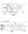
- Figure 4 illustrates the magnetic field sequence employed in the method.
- The method is performed using an apparatus similar to that described in U.K. Patent Specification No..1578910 or No.2056078, to which reference should be made for a fuller description, appropriately programmed to apply a sequence of magnetic field gradient and r.f. pulses and analyse the resulting signals as hereafter described.
- The essential features of such an apparatus in so far as is required for an understanding of the present invention are as follows:
- The apparatus includes a first coil system whereby a magnetic field can be applied to a body to be examined in a given direction, mormally designated the Z-direction, with a gradient in any one or more of the three orthogonal directions i.e. X, Y and Z directions.
- Referring to Figure 1, the first coil system comprises coils 1 capable of providing a steady uniform magnetic field in the Z direction;
coils 3 capable of imposing a magnetic field gradient in the X direction,coils 5 capable of imposing a magnetic field gradient in the Y direction; and coils 7 capable of imposing a magnetic field gradient in the Z direction. - In addition, the apparatus includes a
second coil system 9 whereby r.f. magnetic fields can be applied to the body under examination in a plane normal to the direction of the steady uniform magnetic field produced by the first coil system, and whereby r.f. magnetic fields resulting from nuclei in the body under examination which have been excited to nuclear Magnetic resonance with a spin vector component other than in the Z direction can be detected. - In the drawing a single pair of
coils 9 is shown for both applying and detecting r.f. fields, but in certain circumstances it may be preferable to provide separate coils for detecting the r.f. fields. - The
various coils drive amplifiers control circuits - The
circuits control unit 29 with which are associated inputs andother peripherals 31, for the provision of commands and instructions to the apparatus, and adisplay 33. - The NMR signals detected by the
coils 9 are applied via anamplifier 35 to asignal handling system 37. The signal handling system is arranged to make any appropriate calibration and correction of the signals, but essentially transmits the signals to the processing for application to the display to produce an image representing the distribution of an NMR quantity in the body being examined. - It will be appreciated that whilst shown separately to clarify the present description, the
signal handling system 37 may conveniently form part of theunit 29. - The apparatus also includes field measurement and
error signal circuits 39 which receive signals viaamplifiers 41 from field probes X1, X2' Y1 and Y2 which are disposed at suitable positions in relation to the portion 43 of the body being examined, as illustrated in Figure 2, to monitor the applied magnetic fields. - The apparatus, however, differs from the known forms of apparatus, in that the R.F.
control circuit 27 includes an arrangement shown schematically in Figure 3. This comprises apulse generator 45 capable of simultaneously generating four r.f. pulses each having a limited bandwidth, e.g. of about 5 KHz, and each centred on a different one of four frequencies fl, f2, f3 and f4 such that the frequency bands of the pulses are discrete. The various outputs from thepulse generator 45 are combined inmixer 47, to produce a composite r.f. pulse which is fed via the r.f. driveamplifier 19 to thesecond coil system 9. - Referring now to Figure 4, in use of the apparatus a steady uniform magnetic field, Bo is applied by the first coil system to the body under examination in the Z direction. This field serves to define the equilibrium axis of magnetic alignment of nuclei in the body, i.e. along the Z direction, and remains constant throughout the examination procedure. An additional magnetic field Bz in the Z direction such as to impose a magnetic field gradient Gz in the Z direction is then applied by the coils 7, together with an r.f. magnetic field pulse B1 produced by the arrangement shown in Figure 3. The magnetic field pulse B1 is thus a composite pulse consisting of four component pulses having frequencies centred at fl, f2, f3 and f4. Each of these fre- queneies is chosen to be the Larmor frequency for hydrogen nuclei in a different one of four spaced parallel slices of the portion 43 of the body normal to the Z direction, Sl, S2, S3 and S4 respectively, defined by four particular values of the magnetic field along the Z direction. The integral of the components of the pulse B1 are chosen to be just sufficient to tip the spins of the excited nuclei into the X-Y plane, the spins then precessing in the X-Y plane round the Z axis.
- The gradient Gz is then removed and replaced by a gradient in the opposite sense - Gz. This causes the rephasing the spins within the four slices which have been selectively excited by the combination of the r.f. pulse Bl, the steady uniform field Bo, and the gradient field Bz, the dephasing having been caused by the gradient through each of the slices S1, S2, S3, S4. The magnitude of -Gz is such that the spins are ally all rephased at the time at which this gradient is switched off as described, for example, in the above mentioned U.K. patent specification No. 1,578,910 the excited spins within the four slices then precessing at the same frequency within tbe same magnetic field. A further magnetic field in the Z direction is then applied by the
coils - In order to obtain a two-dimensional NMR image of each of the slices S17 S2, S3, S4 the r.f. and gradient filed sequence together with the processing sequence described herebefore is repceted for each of a large number of different orientations e.g. 180 within the X-Y plane. The images for the four slices are then obtained from the four sets of spatial distribution data for each orientation by a reconstruction technique such as the back projection processing technique.
- It will be appreciated that although the method described herebefore is a method using a projection reconstruction technique, a method in accordance with the invention may alternatively use a two-dimensional Fourier Transformation technique to construct an image, such as described, for example, in J.Mag.Res.29, p.355-373 (1978), J.Mag.Res.18, p.69-83 (1975) and U.K. Patent Specification No. 2056078.
- It will also be appreciated that although the method described herebefore relates to obtaining the spatial distribution of a quantity relating to hydrogen nuclei within the body, the method is equally applicable to any other nuclei having a magnetic spin by appropriate choice of the r.f. pulse frequencies.
- It will also be appreciated that whilst the method described herebefore relates to obtaining images of a number of slices whose planes are orthogonal to the direction of Bo by using a slice selection gradient parallel to Bo, it is equally applicable to a number of slices whose planes lie at a different angle to the direction of Bo by appropriate choice of the direction of the slice selection gradient. In particular in medical applications images of transverse, sagittal and coronal slices may be obtained without moving the patient.
Claims (4)
Applications Claiming Priority (2)
| Application Number | Priority Date | Filing Date | Title |
|---|---|---|---|
| GB8236043 | 1982-12-17 | ||
| GB8236043 | 1982-12-17 |
Publications (3)
| Publication Number | Publication Date |
|---|---|
| EP0112663A2 true EP0112663A2 (en) | 1984-07-04 |
| EP0112663A3 EP0112663A3 (en) | 1985-07-03 |
| EP0112663B1 EP0112663B1 (en) | 1989-01-18 |
Family
ID=10535071
Family Applications (1)
| Application Number | Title | Priority Date | Filing Date |
|---|---|---|---|
| EP83307292A Expired EP0112663B1 (en) | 1982-12-17 | 1983-11-30 | Nuclear magnetic resonance methods and apparatus |
Country Status (5)
| Country | Link |
|---|---|
| US (1) | US4558278A (en) |
| EP (1) | EP0112663B1 (en) |
| JP (1) | JPS59132346A (en) |
| DE (1) | DE3378994D1 (en) |
| GB (1) | GB2131957B (en) |
Cited By (6)
| Publication number | Priority date | Publication date | Assignee | Title |
|---|---|---|---|---|
| DE3545391A1 (en) * | 1984-12-21 | 1986-07-03 | Hitachi, Ltd., Tokio/Tokyo | METHOD FOR GENERATING A MAGNETIC CORE RESONANCE OF AN OBJECT, AND A DEVICE FOR IMPLEMENTING IT |
| EP0213858A2 (en) * | 1985-08-16 | 1987-03-11 | Siemens Aktiengesellschaft | Multiplexed magnetic resonance imaging of volumetric regions |
| EP0460761A1 (en) * | 1990-06-08 | 1991-12-11 | Koninklijke Philips Electronics N.V. | RF coil system in a magnetic resonance imaging apparatus |
| US5093619A (en) * | 1989-08-16 | 1992-03-03 | Spectrospin Ag | Method for the simultaneous measurement of nmr signals, in particular for determining flow rates in nuclear spin tomography by means of the multiple slice fourier flow (muff) method |
| EP0554584A1 (en) * | 1991-11-29 | 1993-08-11 | Koninklijke Philips Electronics N.V. | Magnetic resonance device and signal combination device |
| EP0637756A1 (en) * | 1993-08-06 | 1995-02-08 | Toshiba American Mri, Inc. | Method and apparatus for substantially simultaneously exciting a plurality of slices in NMR imaging |
Families Citing this family (13)
| Publication number | Priority date | Publication date | Assignee | Title |
|---|---|---|---|---|
| IL76009A (en) * | 1985-08-02 | 1989-08-15 | Elscint Ltd | Method for acquiring in-vivo magnetic resonance spectroscopic data |
| US4673880A (en) * | 1985-08-16 | 1987-06-16 | Technicare Corporation | Phase sensitive detection in multislice magnetic resonance imaging systems |
| JPH0811117B2 (en) * | 1986-06-26 | 1996-02-07 | 株式会社東芝 | Pulse sequence method in MRI |
| DE3631039A1 (en) * | 1986-09-12 | 1988-03-24 | Philips Patentverwaltung | Nuclear spin tomography method and nuclear spin tomography for performing the method |
| IL81580A (en) * | 1987-02-16 | 1990-07-26 | Elscint Ltd | Spatial separation of spectral components |
| DE68920782T2 (en) * | 1988-05-13 | 1995-08-10 | Nikon Corp | Automatic focusing device. |
| EP0361190A1 (en) * | 1988-09-23 | 1990-04-04 | Siemens Aktiengesellschaft | Surface coil arrangement for examinations with the aid of nuclear magnetic resonance |
| DE3838792A1 (en) * | 1988-11-17 | 1990-05-31 | Philips Patentverwaltung | Nuclear spin tomography method for determining the core magnetization in a number of parallel layers |
| US5154178A (en) * | 1990-10-09 | 1992-10-13 | Sri International | Method and apparatus for obtaining in-vivo nmr data from a moving subject |
| DE4137217C2 (en) * | 1991-11-13 | 1993-10-07 | Hennig Juergen | Magnetic resonance imaging |
| US6272370B1 (en) | 1998-08-07 | 2001-08-07 | The Regents Of University Of Minnesota | MR-visible medical device for neurological interventions using nonlinear magnetic stereotaxis and a method imaging |
| US6463317B1 (en) | 1998-05-19 | 2002-10-08 | Regents Of The University Of Minnesota | Device and method for the endovascular treatment of aneurysms |
| WO2004106947A2 (en) * | 2003-05-23 | 2004-12-09 | Johns Hopkins University | Steady state free precession based magnetic resonance |
Citations (6)
| Publication number | Priority date | Publication date | Assignee | Title |
|---|---|---|---|---|
| GB2026172A (en) * | 1978-07-20 | 1980-01-30 | Univ California | Method and apparatus for determining the relative densities of nuclei within an object using nuclear magnetic resonance |
| GB1578910A (en) * | 1978-05-25 | 1980-11-12 | Emi Ltd | Imaging systems |
| GB2052753A (en) * | 1979-05-23 | 1981-01-28 | Emi Ltd | NMR systems |
| DE2951537A1 (en) * | 1979-12-20 | 1981-07-02 | Siemens AG, 1000 Berlin und 8000 München | TEMPERATURE METHOD |
| EP0055058A1 (en) * | 1980-12-11 | 1982-06-30 | Picker International Limited | Method of imaging by nuclear magnetic resonance imaging apparatus |
| GB2101327A (en) * | 1981-06-22 | 1983-01-12 | Siemens Ag | Equipment for producing an nmr image as a planar projection |
Family Cites Families (7)
| Publication number | Priority date | Publication date | Assignee | Title |
|---|---|---|---|---|
| GB1580787A (en) * | 1976-04-14 | 1980-12-03 | Mansfield P | Nuclear magnetic resonance apparatus and methods |
| GB1596160A (en) * | 1976-12-15 | 1981-08-19 | Nat Res Dev | Nuclear magnetic resonance apparatus and methods |
| US4318043A (en) * | 1978-07-20 | 1982-03-02 | The Regents Of The University Of California | Method and apparatus for rapid NMR imaging of nuclear densities within an object |
| GB2056078B (en) * | 1979-08-03 | 1984-02-29 | Emi Ltd | Nuclear magnetic resonance systems |
| GB2057142B (en) * | 1979-08-10 | 1983-09-14 | Emi Ltd | Nuclear magnetic resonance systems |
| US4319190A (en) * | 1980-03-06 | 1982-03-09 | Bell Telephone Laboratories, Incorporated | Nuclear magnetic resonance imaging in space and frequency coordinates |
| US4471306A (en) * | 1982-02-03 | 1984-09-11 | General Electric Company | Method of NMR imaging which overcomes T2 * effects in an inhomogeneous static magnetic field |
-
1983
- 1983-11-29 US US06/556,010 patent/US4558278A/en not_active Expired - Fee Related
- 1983-11-30 GB GB08331966A patent/GB2131957B/en not_active Expired
- 1983-11-30 EP EP83307292A patent/EP0112663B1/en not_active Expired
- 1983-11-30 DE DE8383307292T patent/DE3378994D1/en not_active Expired
- 1983-12-16 JP JP58236474A patent/JPS59132346A/en active Pending
Patent Citations (6)
| Publication number | Priority date | Publication date | Assignee | Title |
|---|---|---|---|---|
| GB1578910A (en) * | 1978-05-25 | 1980-11-12 | Emi Ltd | Imaging systems |
| GB2026172A (en) * | 1978-07-20 | 1980-01-30 | Univ California | Method and apparatus for determining the relative densities of nuclei within an object using nuclear magnetic resonance |
| GB2052753A (en) * | 1979-05-23 | 1981-01-28 | Emi Ltd | NMR systems |
| DE2951537A1 (en) * | 1979-12-20 | 1981-07-02 | Siemens AG, 1000 Berlin und 8000 München | TEMPERATURE METHOD |
| EP0055058A1 (en) * | 1980-12-11 | 1982-06-30 | Picker International Limited | Method of imaging by nuclear magnetic resonance imaging apparatus |
| GB2101327A (en) * | 1981-06-22 | 1983-01-12 | Siemens Ag | Equipment for producing an nmr image as a planar projection |
Cited By (10)
| Publication number | Priority date | Publication date | Assignee | Title |
|---|---|---|---|---|
| DE3545391A1 (en) * | 1984-12-21 | 1986-07-03 | Hitachi, Ltd., Tokio/Tokyo | METHOD FOR GENERATING A MAGNETIC CORE RESONANCE OF AN OBJECT, AND A DEVICE FOR IMPLEMENTING IT |
| US4757260A (en) * | 1984-12-21 | 1988-07-12 | Hitachi, Ltd. | Method of producing nuclear magnetic resonance of an object and an apparatus therefor |
| EP0213858A2 (en) * | 1985-08-16 | 1987-03-11 | Siemens Aktiengesellschaft | Multiplexed magnetic resonance imaging of volumetric regions |
| EP0213858A3 (en) * | 1985-08-16 | 1988-03-02 | Technicare Corporation | Multiplexed magnetic resonance imaging of volumetric regions |
| US5093619A (en) * | 1989-08-16 | 1992-03-03 | Spectrospin Ag | Method for the simultaneous measurement of nmr signals, in particular for determining flow rates in nuclear spin tomography by means of the multiple slice fourier flow (muff) method |
| EP0460761A1 (en) * | 1990-06-08 | 1991-12-11 | Koninklijke Philips Electronics N.V. | RF coil system in a magnetic resonance imaging apparatus |
| US5272437A (en) * | 1990-06-08 | 1993-12-21 | U.S. Philips Corporation | RF coil system in a magnetic resonance imaging apparatus |
| EP0554584A1 (en) * | 1991-11-29 | 1993-08-11 | Koninklijke Philips Electronics N.V. | Magnetic resonance device and signal combination device |
| EP0637756A1 (en) * | 1993-08-06 | 1995-02-08 | Toshiba American Mri, Inc. | Method and apparatus for substantially simultaneously exciting a plurality of slices in NMR imaging |
| US5422572A (en) * | 1993-08-06 | 1995-06-06 | Toshiba America Mri, Inc. | Method and apparatus for substantially simultaneously exciting a plurality of slices in NMR imaging |
Also Published As
| Publication number | Publication date |
|---|---|
| EP0112663A3 (en) | 1985-07-03 |
| US4558278A (en) | 1985-12-10 |
| GB2131957A (en) | 1984-06-27 |
| JPS59132346A (en) | 1984-07-30 |
| GB8331966D0 (en) | 1984-01-04 |
| EP0112663B1 (en) | 1989-01-18 |
| GB2131957B (en) | 1986-09-24 |
| DE3378994D1 (en) | 1989-02-23 |
Similar Documents
| Publication | Publication Date | Title |
|---|---|---|
| US4558278A (en) | Nuclear magnetic resonance methods and apparatus | |
| US4563647A (en) | Nuclear magnetic resonance methods and apparatus | |
| US4734646A (en) | Method for obtaining T1-weighted and T2-weighted NMR images for a plurality of selected planes in the course of a single scan | |
| US4520828A (en) | Nuclear magnetic resonance method and apparatus | |
| EP0167350B1 (en) | Nuclear magnetic resonance method and apparatus | |
| EP0100183B1 (en) | Nuclear magnetic resonance method and apparatus | |
| US4902973A (en) | Separation of spectral components | |
| US4733183A (en) | Nuclear magnetic resonance methods and apparatus | |
| US4642568A (en) | Nuclear magnetic resonance methods and apparatus | |
| EP0103388B1 (en) | Nuclear magnetic resonance methods and apparatus | |
| EP0109238B1 (en) | Nuclear magnetic resonance method and apparatus | |
| US4684892A (en) | Nuclear magnetic resonance apparatus | |
| US4646023A (en) | Nuclear magnetic resonance imaging | |
| EP0217578B1 (en) | Nuclear magnetic resonance methods and apparatus | |
| EP0106472B1 (en) | Nuclear magnetic resonance method and apparatus | |
| US4703269A (en) | Nuclear magnetic resonance imaging methods and apparatus | |
| EP0129356A2 (en) | Nuclear magnetic resonance method and apparatus | |
| US4721911A (en) | Nuclear magnetic resonance tomography apparatus | |
| JPS6266846A (en) | Nmr examination apparatus using chemical shift value | |
| EP0109517B1 (en) | Nuclear magnetic resonance diagnostic apparatus | |
| JP2695594B2 (en) | MRI equipment | |
| GB2160660A (en) | Nuclear magnetic resonance (NMR) imaging |
Legal Events
| Date | Code | Title | Description |
|---|---|---|---|
| PUAI | Public reference made under article 153(3) epc to a published international application that has entered the european phase |
Free format text: ORIGINAL CODE: 0009012 |
|
| AK | Designated contracting states |
Designated state(s): DE FR NL |
|
| PUAL | Search report despatched |
Free format text: ORIGINAL CODE: 0009013 |
|
| AK | Designated contracting states |
Designated state(s): DE FR NL |
|
| 17P | Request for examination filed |
Effective date: 19851212 |
|
| 17Q | First examination report despatched |
Effective date: 19870514 |
|
| GRAA | (expected) grant |
Free format text: ORIGINAL CODE: 0009210 |
|
| AK | Designated contracting states |
Kind code of ref document: B1 Designated state(s): DE FR NL |
|
| REF | Corresponds to: |
Ref document number: 3378994 Country of ref document: DE Date of ref document: 19890223 |
|
| ET | Fr: translation filed | ||
| PGFP | Annual fee paid to national office [announced via postgrant information from national office to epo] |
Ref country code: FR Payment date: 19891030 Year of fee payment: 7 |
|
| PLBE | No opposition filed within time limit |
Free format text: ORIGINAL CODE: 0009261 |
|
| STAA | Information on the status of an ep patent application or granted ep patent |
Free format text: STATUS: NO OPPOSITION FILED WITHIN TIME LIMIT |
|
| PGFP | Annual fee paid to national office [announced via postgrant information from national office to epo] |
Ref country code: NL Payment date: 19891130 Year of fee payment: 7 |
|
| 26N | No opposition filed | ||
| PGFP | Annual fee paid to national office [announced via postgrant information from national office to epo] |
Ref country code: DE Payment date: 19900125 Year of fee payment: 7 |
|
| PG25 | Lapsed in a contracting state [announced via postgrant information from national office to epo] |
Ref country code: NL Effective date: 19910601 |
|
| NLV4 | Nl: lapsed or anulled due to non-payment of the annual fee | ||
| PG25 | Lapsed in a contracting state [announced via postgrant information from national office to epo] |
Ref country code: FR Effective date: 19910731 |
|
| PG25 | Lapsed in a contracting state [announced via postgrant information from national office to epo] |
Ref country code: DE Effective date: 19910801 |
|
| REG | Reference to a national code |
Ref country code: FR Ref legal event code: ST |