EP0117177B1 - Sac à vide préétabli pour conservation de produits divers - Google Patents
Sac à vide préétabli pour conservation de produits divers Download PDFInfo
- Publication number
- EP0117177B1 EP0117177B1 EP84400148A EP84400148A EP0117177B1 EP 0117177 B1 EP0117177 B1 EP 0117177B1 EP 84400148 A EP84400148 A EP 84400148A EP 84400148 A EP84400148 A EP 84400148A EP 0117177 B1 EP0117177 B1 EP 0117177B1
- Authority
- EP
- European Patent Office
- Prior art keywords
- bag
- auxiliary pocket
- hole
- added sheet
- Prior art date
- Legal status (The legal status is an assumption and is not a legal conclusion. Google has not performed a legal analysis and makes no representation as to the accuracy of the status listed.)
- Expired
Links
Images
Classifications
-
- B—PERFORMING OPERATIONS; TRANSPORTING
- B65—CONVEYING; PACKING; STORING; HANDLING THIN OR FILAMENTARY MATERIAL
- B65D—CONTAINERS FOR STORAGE OR TRANSPORT OF ARTICLES OR MATERIALS, e.g. BAGS, BARRELS, BOTTLES, BOXES, CANS, CARTONS, CRATES, DRUMS, JARS, TANKS, HOPPERS, FORWARDING CONTAINERS; ACCESSORIES, CLOSURES, OR FITTINGS THEREFOR; PACKAGING ELEMENTS; PACKAGES
- B65D31/00—Bags or like containers made of paper and having structural provision for thickness of contents
- B65D31/12—Bags or like containers made of paper and having structural provision for thickness of contents with two or more compartments
-
- B—PERFORMING OPERATIONS; TRANSPORTING
- B65—CONVEYING; PACKING; STORING; HANDLING THIN OR FILAMENTARY MATERIAL
- B65D—CONTAINERS FOR STORAGE OR TRANSPORT OF ARTICLES OR MATERIALS, e.g. BAGS, BARRELS, BOTTLES, BOXES, CANS, CARTONS, CRATES, DRUMS, JARS, TANKS, HOPPERS, FORWARDING CONTAINERS; ACCESSORIES, CLOSURES, OR FITTINGS THEREFOR; PACKAGING ELEMENTS; PACKAGES
- B65D81/00—Containers, packaging elements, or packages, for contents presenting particular transport or storage problems, or adapted to be used for non-packaging purposes after removal of contents
- B65D81/18—Containers, packaging elements, or packages, for contents presenting particular transport or storage problems, or adapted to be used for non-packaging purposes after removal of contents providing specific environment for contents, e.g. temperature above or below ambient
- B65D81/20—Containers, packaging elements, or packages, for contents presenting particular transport or storage problems, or adapted to be used for non-packaging purposes after removal of contents providing specific environment for contents, e.g. temperature above or below ambient under vacuum or superatmospheric pressure, or in a special atmosphere, e.g. of inert gas
- B65D81/2007—Containers, packaging elements, or packages, for contents presenting particular transport or storage problems, or adapted to be used for non-packaging purposes after removal of contents providing specific environment for contents, e.g. temperature above or below ambient under vacuum or superatmospheric pressure, or in a special atmosphere, e.g. of inert gas under vacuum
- B65D81/2023—Containers, packaging elements, or packages, for contents presenting particular transport or storage problems, or adapted to be used for non-packaging purposes after removal of contents providing specific environment for contents, e.g. temperature above or below ambient under vacuum or superatmospheric pressure, or in a special atmosphere, e.g. of inert gas under vacuum in a flexible container
-
- B—PERFORMING OPERATIONS; TRANSPORTING
- B65—CONVEYING; PACKING; STORING; HANDLING THIN OR FILAMENTARY MATERIAL
- B65D—CONTAINERS FOR STORAGE OR TRANSPORT OF ARTICLES OR MATERIALS, e.g. BAGS, BARRELS, BOTTLES, BOXES, CANS, CARTONS, CRATES, DRUMS, JARS, TANKS, HOPPERS, FORWARDING CONTAINERS; ACCESSORIES, CLOSURES, OR FITTINGS THEREFOR; PACKAGING ELEMENTS; PACKAGES
- B65D81/00—Containers, packaging elements, or packages, for contents presenting particular transport or storage problems, or adapted to be used for non-packaging purposes after removal of contents
- B65D81/18—Containers, packaging elements, or packages, for contents presenting particular transport or storage problems, or adapted to be used for non-packaging purposes after removal of contents providing specific environment for contents, e.g. temperature above or below ambient
- B65D81/20—Containers, packaging elements, or packages, for contents presenting particular transport or storage problems, or adapted to be used for non-packaging purposes after removal of contents providing specific environment for contents, e.g. temperature above or below ambient under vacuum or superatmospheric pressure, or in a special atmosphere, e.g. of inert gas
- B65D81/2007—Containers, packaging elements, or packages, for contents presenting particular transport or storage problems, or adapted to be used for non-packaging purposes after removal of contents providing specific environment for contents, e.g. temperature above or below ambient under vacuum or superatmospheric pressure, or in a special atmosphere, e.g. of inert gas under vacuum
- B65D81/2038—Containers, packaging elements, or packages, for contents presenting particular transport or storage problems, or adapted to be used for non-packaging purposes after removal of contents providing specific environment for contents, e.g. temperature above or below ambient under vacuum or superatmospheric pressure, or in a special atmosphere, e.g. of inert gas under vacuum with means for establishing or improving vacuum
Definitions
- the invention relates to a bag with flexible walls and a tight closure for the vacuum storage of various products.
- Document FR-A-2 428 587 already discloses a package for the packaging of products under high vacuum composed of two plastic sheets which are first joined by welding on three sides; the bag thus formed is filled by the side left open and the latter is also sealed. One of the sheets is provided with a valve which is then used to connect the packaging to a vacuum chamber in order to draw the air contained in this packaging. It is therefore necessary to have a source of vacuum when filling the bag, which is precisely what the invention wants to avoid.
- the subject of the invention is a bag in which a vacuum reserve is established in advance so that the use of this bag does not require the user to have a machine or an apparatus for evacuating when it encloses in the bag of the products to be preserved.
- a bag with flexible walls and with tight closure for the vacuum storage of various products according to the invention contains an auxiliary pocket limiting a volume which is empty of air before the bag is used; this auxiliary pocket is provided with a means of communicating its volume with that of the bag when the latter has been sealed.
- auxiliary pocket into the bag and to limit the volume thereof by a wall which is common with at least one wall of the bag, and by an attached sheet and fixed to the face. inside of the bag.
- the insert sheet is preferably pleated or embossed to give the bag minimum bulk when it is empty of air.
- the attached sheet may have a central zone of tearable weakening constituting a means of communication between the pocket and the bag.
- this means may consist of a hole provided in the attached sheet and of a plate closing this hole with a breaking groove in this plate passing in front of the hole; the same means can also be constituted by a pointed central protuberance enabling the perforated sheet to be perforated. This pointed central protuberance can be suspended on one side of the attached sheet in front of an opposing washer pierced with a hole and fixed on the other side of the attached sheet.
- the auxiliary pocket is a box made of rigid material provided with an easily breakable appendage having an internal channel which opens onto the interior volume of the auxiliary pocket.
- the auxiliary pocket is advantageously provided with elastic means tending to restore it to its original shape after crushing.
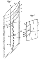
- the bag of Figure 1 is shown open, in section through a longitudinal plane passing through its middle, the front part drawn in phantom being assumed to be removed to reveal the rear part drawn in solid line.
- This bag can be made of any suitable material, transparent or opaque, flexible; for example the flexible walls 2, 3 can be produced from two polyethylene sheets which are welded on three sides to leave an upper filling opening 4. It is capable of being sealed in a leaktight manner after filling, in a known manner , either by hot welding, or by means of a transverse strip 5 of adhesive material provided a little below the upper opening 4.
- the invention is compatible with any type of bag and with any sealing method.
- the bag 1 contains an auxiliary pocket 6 which limits a volume which has been emptied of its air at the time of manufacture.
- the auxiliary pocket 6 is obtained using an additional sheet 7 added of flexible material which is welded to the inner face of one of the walls 3 of the bag 1.
- the welding is carried out along the four edges of the additional sheet 7.
- the latter is folded or corrugated, thanks to corrugations 8 which prevent the two opposite walls of the auxiliary pocket 6 from adhering to each other when the vacuum has been created in the latter and which allow the pocket to inflate when air enters it.
- Wrinkling or waving is not always necessary; other means can be used to prevent adhesion of the opposite walls of the auxiliary pocket 6 while allowing it to swell.
- an area 9 of the additional sheet 7 is smooth; it is used for fixing, for example by gluing, a plate 10, better visible in Figure 2, which constitutes a means of communication, when desired, the interior of the bag 1 with the empty volume d air from the auxiliary pocket 6.
- the additional sheet 7 is pierced with a hole 11 which is covered and closed by a flat main face 10A of the wafer 10.
- the wafer 10 On its opposite main face 10B the wafer 10 has a transverse groove 12 which constitutes a starting point and which passes in front of the hole 11. This groove 12 could be on the main face 1 OA just in front of the hole 11 if it did not extend to the two opposite edges of the wafer 10.
- the pocket 6 is emptied of its air. After filling the bag 1 in products to be stored under vacuum, it is sealed in the usual manner provided, then, through the walls 2, 3 one grasps the plate 10 and breaks it along the groove 12. The hole 11 then allows the air contained in the bag 1 to enter the auxiliary pocket 6 which inflates.
- the air pressure in the assembly consisting of the bag 1 and the auxiliary pocket 6 is reduced by the same amount and it becomes significantly lower than atmospheric pressure, according to the ratio between the volume of the bag 1, its degree of filling, the volume of the auxiliary bag 6 and the degree of vacuum produced in it at the time of manufacture.
- the plate 10 is fixed to the outside face of the additional sheet 7 relative to the pocket 6. It could be fixed over the hole 11 on the inside face of this sheet 7, that is to say ie inside the pocket 6. It would then serve to prevent the adhesion of the two opposite sheets 7 and 3 of this pocket.
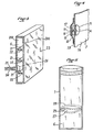
- FIG 4 shows an alternative embodiment of the communication means.
- the additional sheet 7 is not pierced.
- an opposing washer 13 pierced with a central hole 14.
- a second washer 15 having a central hole 16 and a pointed central protuberance 17 held suspended by means of a flexible sheet 18. The latter is welded at its periphery to the additional sheet 7 and it is pierced with a hole 19 just opposite the hole 16.
- the pointed central protuberance 17 is located opposite the hole 14 of the first opposing washer 13.
- the auxiliary pocket 6 is incorporated into the bag 1, inside of it, at the very time of its manufacture. It will be noted that the auxiliary pocket 6 could be made outside the bag 1 by fitting and fixing the additional sheet 7 outside the wall 3. In this case, it is this which would be provided a means of communication.
- FIG. 3 shows an auxiliary pocket 6 made of rigid molded material, having two opposite main walls 20A, 20B held spaced apart by internal partitions 21 pierced with communication holes 22 which could be replaced by total interruptions of the partitions 21, for example at one end of it.
- the auxiliary pocket is analogous to a box; it is independent of the bag into which it is introduced when the latter is used; preferably it has an outer face covered with a layer of adhesive material 23 which makes it possible, if it is deemed desirable, to fix it to an inner face of a bag 1.
- the auxiliary pocket 6 of FIG. 3 is provided with an appendage 24 in which is formed an interior channel 25 which communicates with the interior volume of the pocket 6 but which is closed relative to the exterior.
- Appendix 24 is easily breakable; it can have predetermined breaking lines, if desired. It is easily broken through the walls 2, 3 of the bag 1 when the latter has been filled and sealed.
- the channel 25 of the appendix 24 is preferably filled with a porous material allowing the air to circulate slowly between the bag 1 and the auxiliary pocket 6.
- the appendix 24 could be provided with a base 26 similar to a washer cut out from the wall of the box, as indicated in phantom. This washer could be attached to the additional sheet 7, the hole 11 thereof in Figure 2 being in the extension of the channel 25. There would thus be, with an auxiliary pocket 6 incorporated in the bag 1, another means of setting communication between the bag and the auxiliary pocket.
- FIG. 5 shows a bag 1 in which the auxiliary pocket 6 is produced using a transverse partition (attached sheet 27) which has a raised edge 28 by which it is welded to the inner face of the bag 1, after making of the last.
- This partition 27 has a central zone 29 of predetermined weakening which makes it possible to crack it when one pulls on either side of this zone 29, through the walls of the bag 1 previously filled and sealed.
- the vacuum in the auxiliary pocket 6 of the invention is obtained by any available means.
- Air can be drawn in using an air pump.
- the auxiliary pocket 6 has rigid walls as in the example in FIG. 3, it retains its shape. After filling the bag 1 with products to be preserved, as soon as this auxiliary bag 6 is placed in communication with the bag 1, the residual air spreads itself in this bag 6.
- FIG. 5 relates to an example of an auxiliary bag and pocket where the walls are of semi-rigid and elastic material tending to retain or resume their initial shape after the air has been drawn in.
- auxiliary pocket 6 when the auxiliary pocket 6 is provided with elastic means, a vacuum can be created there without using an air pump. Just flatten this pocket before closing it tightly. When it then returns to its original shape, it is empty of air.
- the auxiliary pocket 6 can be given suitable elasticity by making it with semi-rigid and elastic walls capable of resuming their initial shape after crushing. If the walls are not capable of resuming their initial shape alone, an internal spring can be provided which tends to spread these walls apart; in Figure 1 there is drawn in phantom an inner spring 30 of spacing. This spring 30 is held in its place by guide means, not shown.
- the elastic means are incorporated into the walls of the auxiliary pocket 6 or attached to this pocket as elastic spacer elements.
- the volume filled with air from the auxiliary pocket 6 need not be of considerable importance. If the bag 1 to be filled has a volume V, after filling, it contains only a residual volume of air v which may be very small. If the pocket auxiliary 6 filled with air has a volume equal to 10 v, when it has been emptied of its air to a practically zero pressure and then it is placed in communication with the residual air volume v, the pressure in the bag 1 becomes one tenth of the atmospheric pressure. The largest fraction of the residual air is then found in the auxiliary pocket 6. The communication means in all cases has only a very small passage section, in particular when an appendage 24 with an internal channel is used. 25 filled with porous material. As a result, the largest fraction of the residual air is trapped in the auxiliary pocket and isolated from the products contained in the bag. The latter can therefore be used by anyone in any place without a vacuum machine.
Description
- L'invention concerne un sac à parois souples et à fermeture étanche pour la conservation sous vide de produits divers.
- On connaît déjà par le document FR-A-2 428 587 un emballage pour le conditionnement de produits sous vide poussé composé de deux feuilles en matière plastique qui sont d'abord réunies par soudure sur trois côtés; le sac ainsi formé est rempli par le côté laissé ouvert puis ce dernier est scellé aussi. L'une des feuilles est pourvue d'une valve que l'on utilise alors pour relier l'emballage à une chambre de vide afin d'aspirer l'air contenu dans cet emballage. Il est donc nécessaire de disposer d'une source de vide au moment où on remplit le sac, ce qui est précisément ce que l'invention veut éviter.
- L'invention a pour objet un sac dans lequel est établie à l'avance une réserve de vide de sorte que l'emploi de ce sac ne nécessite pas que l'utilisateur dispose d'une machine ou d'un appareil pour faire le vide au moment où il enferme dans le sac des produits à conserver.
- Un sac à parois souples et à fermeture étanche pour la conservation sous vide de produits divers conforme à l'invention contient une poche auxiliaire limitant un volume qui est vide d'air avant l'utilisation du sac; cette poche auxiliaire est munie d'un moyen de mise en communication de son volume avec celui du sac quand celui-ci a été fermé de façon étanche.
- Il est préférable, bien que non obligatoire, d'incorporer au sac la poche auxiliaire et de limiter le volume de celle-ci par une paroi qui est commune avec au moins une paroi du sac, et par une feuille rapportée et fixée à la face intérieure du sac.
- La feuille rapportée est, de préférence, plissée ou gaufrée pour donner un encombrement minimum à la poche quand elle est vide d'air.
- La feuille rapportée peut présenter une zone centrale d'affaiblissement déchirable constituant un moyen de mise en communication entre la poche et le sac. En variante, ce moyen peut consister en un trou prévu dans la feuille rapportée et en une plaquette obturant ce trou avec une rainure de rupture dans cette plaquette passant devant le trou; le même moyen peut encore être constitué par une protubérance centrale pointue permettant de perforer la feuille rapportée. Cette protubérance centrale pointue peut être suspendue d'un côté de la feuille rapportée en face d'une rondelle antagoniste percée d'un trou et fixée de l'autre côté de la feuille rapportée.
- Selon un mode de réalisation de l'invention, la poche auxiliaire est une boîte en matière rigide pourvue d'un appendice facilement cassable ayant un canal intérieur qui s'ouvre sur le volume intérieur de la poche auxiliaire.
- La poche auxiliaire est avantageusement pourvue de moyens élastiques tendant à lui redonner sa forme initiale après écrasement.
- On donnera maintenant, sans intention limitative es sans exclure aucune variante, une description de plusieurs exemples de sacs conformes à l'invention. On se reportera aux dessins annexés dans lesquels:
- la figure 1 est une vue générale en perspective et en coupe d'un sac conforme à l'invention, la partie manquante étant représentée en trait mixte,
- la figure 2 est une vue partielle agrandie, en coupe, et en perspective montrant un moyen de communication entre le sac et la poche auxiliaire,
- la figure 3 est une vue en perspective et en coupe d'un autre moyen de communication entre le sac et la poche auxiliaire,
- la figure 4 est une vue en perspective et en coupe d'un autre moyen de communication entre le sac et la poche auxiliaire,
- la figure 5 est une vue en perspective d'une variante de réalisation d'un sac selon l'invention.
- Le sac de la figure 1 est représenté ouvert, en coupe par un plan longitudinal passant par son milieu, la partie avant dessinée en trait mixte étant supposée enlevée pour laisser voir la partie arrière dessinée en trait plein. Ce sac peut être réalisé en toute matière convenable, transparente ou opaque, souple; par example les parois souples 2, 3 sont réalisable à partir de deux feuilles de polyéthylène qui sont soudées sur trois côtés pour laisser une ouverture supérieure de remplissage 4. Il est susceptible d'être scellé, de façon étanche après son remplissage, de manière connue, soit par soudure à chaud, soit grâce à une bande transversale 5 de matière adhésive prévue un peu en dessous de l'ouverture supérieure 4. Linven- tion est compatible avec tout type de sac et avec tout procédé de fermeture étanche.
- Selon l'invention le sac 1 contient une poche auxiliaire 6 qui limite un volume que l'on a vidé de son air au moment de la fabrication.
- Sur la figure 1, la poche auxiliaire 6 est obtenue à l'aide d'une feuille supplémentaire 7 rapportée de matière souple qui est soudée à la face intérieure de l'une des parois 3 du sac 1. La soudure est faite le long des quatre bords de la feuille supplémentaire 7. De préférence, cette dernière est plissée ou ondulée, grâce à des ondulations 8 qui empêchent que les deux parois opposées de la poche auxiliaire 6 adhèrent l'une à l'autre quand le vide a été fait dans cette dernière et qui permettent à la poche de se gonfler quand de l'air y entre.
- Le plissement ou les ondulations ne sont pas toujours nécessaires; d'autres moyens peuvent servir à empêcher l'adhérence des parois opposées de la poche auxiliaire 6 tout en autorisant son gonflement.
- Dans l'exemple de la figure 1, une zone 9 de la feuille supplémentaire 7 est lisse; elle sert à la fixation, par exemple par collage, d'une plaquette 10, mieux visible sur la figure 2, qui constitue un moyen de mise en communication, quand on le désire, de l'intérieur du sac 1 avec le volume vide d'air de la poche auxiliaire 6. A cet effet, la feuille supplémentaire 7 est percée d'un trou 11 qui est recouvert et obturé par une face principale plane 10A de la plaquette 10. Sur sa face principale opposée 10B la plaquette 10 présente une rainure transversale 12 qui constitue une amorce de rupture et qui passe devant le trou 11. Cette rainure 12 pourrait se trouver sur la face principale 1 OA juste devant le trou 11 si elle ne s'étendait pas jusqu'aux deux bords opposés de la plaquette 10.
- Au moment de la fabrication du sac 1, la poche 6 est vidée de son air. Après remplissage du sac 1 en produits à conserver sous vide, on le scelle de la manière habituelle prévue, puis, à travers les parois 2, 3 on saisit la plaquette 10 et on la casse le long de la rainure 12. Le trou 11 permet alors à l'air contenu dans le sac 1 de pénétrer dans la poche auxiliaire 6 qui se gonfle. La pression de l'air dans l'ensemble composé du sac 1 et de la poche auxiliaire 6 est réduite d'autant et elle devient notablement inférieure à la pression atmosphérique, selon le rapport entre le volume du sac 1, son degré de remplissage, le volume de la poche auxiliaire 6 et le degré de vide réalisé dans celle-ci au moment de la fabrication.
- On remarquera sur la figure 2 que la plaquette 10 est fixée à la face extérieure de la feuille supplémentaire 7 par rapport à la poche 6. On pourrait la fixer par dessus le trou 11 sur la face intérieure de cette feuille 7, c'est-à-dire à l'intérieur de la poche 6. Elle servirait alors à empêcher l'adhérence des deux feuilles opposées 7 et 3 de cette poche.
- La figure 4 montre une variante de réalisation du moyen de mise en communication. Dans ce cas, la feuille supplémentaire 7 n'est pas percée. Sur sa face intérieure 7A est fixée une rondelle antagoniste 13 percée d'un trou central 14. Du côté de la face opposée 7B une seconde rondelle 15 ayant un trou central 16 et une protubérance centrale pointue 17 esttenue suspendue au moyen d'une feuille souple 18. Celle-ci est soudée à son pourtour à la feuille supplémentaire 7 et elle est percée d'un trou 19 juste en face du trou 16. La protubérance centrale pointue 17 se trouve en face du trou 14 de la première rondelle antagoniste 13. Quand on serre entre les doigts les deux rondelles 13, 15, après avoir rempli et scellé le sac, la protubérance perfore la feuille supplémentaire 7 et l'air peut passer par les trous 19, 16, 14.
- Dans l'exemple décrit ci-dessus, la poche auxiliaire 6 est incorporée au sac 1, à l'intérieur de celui-ci, au moment même de sa fabrication. On notera que l'on pourrait réaliser la poche auxiliaire 6 à l'extérieur du sac 1 en rapportant et en fixant la feuille supplémentaire 7 à l'extérieur de la paroi 3. Dans ce cas, c'est celle-ci qui serait pourvue d'un moyen de mise en communication.
- La figure 3 montre une poche auxiliaire 6 réalisée en matière moulée rigide, ayant deux parois principales opposées 20A, 20B tenues espacées par des cloisons intérieures 21 percées de trous de communication 22 qui pourraient être remplacés par des interruptions totales des cloisons 21, par exemple à une extrémité de celle-ci. La poche auxiliaire est analogue à une boîte; elle est indépendante du sac dans lequel on l'introduit au moment de l'utilisation de ce dernier; de préférence elle a une face extérieure recouverte d'une couche de matière adhésive 23 qui permet, si on le juge souhaitable, de la fixer à une face intérieure d'un sac 1. La poche auxiliaire 6 de la figure 3 est pourvue d'un appendice 24 dans lequel est ménagé un canal intérieur 25 qui communique avec le volume intérieur de la poche 6 mais qui est obturé par rapport à l'extérieur. L'appendice 24 est facilement cassable; il peut présenter des lignes prédéterminées de rupture, si on le souhaite. On le brise facilement à travers les parois 2, 3 du sac 1 quand celui-ci a été rempli et scellé. Le canal 25 de l'appendice 24 est rempli de préférence d'une matière poreuse laissant l'air circuler lentement entre le sac 1 et la poche auxiliaire 6.
- On remarquera que l'appendice 24 pourrait être pourvu d'une base 26 analogue à une rondelle découpée dans la paroi de la boite, comme indiqué en trait mixte. Cette rondelle pourrait être fixée à la feuille supplémentaire 7, le trou 11 de celle-ci sur la figure 2 étant dans le prolongement du canal 25. On aurait ainsi, avec une poche auxiliaire 6 incorporée au sac 1, un autre moyen de mise en communication entre le sac et la poche auxiliaire.
- La figure 5 montre un sac 1 dans lequel la poche auxiliaire 6 est réalisée à l'aide d'une cloison transversale (feuille rapportée 27) qui a un bord relevé 28 par lequel elle est soudée à la face intérieure du sac 1, après confection de ce dernier. Cette cloison 27 a une zone centrale 29 d'affaiblissement prédéterminé qui permet de la fissurer quand on tire de part et d'autre de cette zone 29, à travers les parois du sac 1 préalablement rempli et scellé.
- Le vide d'air réalisé dans la poche auxiliaire 6 de l'invention s'obtient par tous moyens disponibles.
- On peut aspirer l'air à l'aide d'une pompe à air. Quand la poche auxiliaire 6 a des parois rigides comme dans l'exemple de la figure 3, elle conserve sa forme. Après remplissage du sac 1 en produits à conserver, dès la mise en communication de cette poche auxiliaire 6 avec le sac 1, l'air résiduel se répand de lui-même dans cette poche 6.
- Quand la poche auxiliaire 6 n'a pas des parois totalement rigides, elle s'aplatit quand elle a été vidée de son air. Il est souhaitable de lui donner des moyens élastiques qui tendent à lui faire reprendre sa forme initiale après la création du vide, soit avant soit après l'établissement de la communication entre cette poche auxiliaire 6 et le volume intérieur du sac 1. La figure 5 se rapporte à un exemple de sac et de poche auxiliaire où les parois sont en matière semi-rigide et élastique tendant à conserver ou à reprendre leur forme initiale après l'aspiration de l'air.
- Il est intéressant de noter que lorsque la poche auxiliaire 6 est pourvu de moyens élastiques, on peut y faire le vide sans se servir d'une pompe à air. Il suffit d'aplatir cette poche avant de la fermer hermétiquement. Quand elle reprend ensuite sa forme initiale, elle est vide d'air.
- On peut donner à la poche auxiliaire 6 une élasticité convenable en la réalisant avec des parois semi- rigides et élastiques capables de reprendre leur forme initiale après écrasement. Si les parois ne sont pas capables de reprendre seules leur forme initiale, on peut prévoir un ressort intérieur qui tend à écarter ces parois; sur la figure 1 on a dessiné en trait mixte un ressort intérieur 30 d'écartement. Ce ressort 30 est tenu à sa place par des moyens de guidage non représentés.
- Par conséquent, les moyens élastiques sont incorporés aux parois de la poche auxiliaire 6 ou rapportés à cette poche comme des éléments élastiques d'écartement.
- On notera que le volume rempli d'air de la poche auxiliaire 6 n'a pas besoin d'avoir une importance considérable. Si le sac 1 à remplir a un volume V, après remplissage, il ne contient plus qu'un volume d'air résiduel v qui peut être très petit. Si la poche auxiliaire 6 remplie d'air a un volume égal à 10 v, lorsqu'elle a été vidée de son air jusqu'à une pression pratiquement nulle et qu'elle est mise ensuite en communication avec le volume d'air résiduel v, la pression dans le sac 1 devient le dixième de la pression atmosphérique. La plus grande fraction de l'air résiduel se trouve alors dans la poche auxiliaire 6. Le moyen de mise en communication n'a dans tous les cas qu'une section de passage très réduite, notamment quand on emploie un appendice 24 à canal intérieur 25 rempli de matière poreuse. Il en résulte que la plus grande fraction de l'air résiduel est emprisonnée dans la poche auxiliaire et isolée des produits contenus dans le sac. Ce dernier est donc utilisable par toute personne en tout endroit dépourvu de machine à faire le vide.
Claims (11)
Applications Claiming Priority (2)
| Application Number | Priority Date | Filing Date | Title |
|---|---|---|---|
| FR8301077 | 1983-01-25 | ||
| FR8301077A FR2539709A1 (fr) | 1983-01-25 | 1983-01-25 | Sac a vide preetabli pour conservation de produits divers |
Publications (2)
| Publication Number | Publication Date |
|---|---|
| EP0117177A1 EP0117177A1 (fr) | 1984-08-29 |
| EP0117177B1 true EP0117177B1 (fr) | 1986-11-20 |
Family
ID=9285252
Family Applications (1)
| Application Number | Title | Priority Date | Filing Date |
|---|---|---|---|
| EP84400148A Expired EP0117177B1 (fr) | 1983-01-25 | 1984-01-24 | Sac à vide préétabli pour conservation de produits divers |
Country Status (4)
| Country | Link |
|---|---|
| US (1) | US4576283A (fr) |
| EP (1) | EP0117177B1 (fr) |
| DE (2) | DE117177T1 (fr) |
| FR (1) | FR2539709A1 (fr) |
Families Citing this family (56)
| Publication number | Priority date | Publication date | Assignee | Title |
|---|---|---|---|---|
| US5314069A (en) * | 1985-03-28 | 1994-05-24 | Deltagraph A/S | Process for obtaining a package containing mutually reactive particulate materials and a package containing such materials |
| US4756422A (en) * | 1985-09-23 | 1988-07-12 | Kristen Hanns J | Plastic bag for vacuum sealing |
| USRE34929E (en) * | 1985-09-23 | 1995-05-09 | Tilia, Inc. | Plastic bag for vacuum sealing |
| JPH01215262A (ja) * | 1988-02-25 | 1989-08-29 | Yoshio Tanaka | 真空包装ドナリエラ藻体含有食品の製造法 |
| EP0489269B1 (fr) * | 1990-12-05 | 1995-09-13 | Firmenich Sa | Emballage en matière plastique à compartiments multiples pour produits liquides et solides |
| US5544752A (en) * | 1995-02-09 | 1996-08-13 | Cox; Dean M. | Evacuable storage bag |
| US5839582A (en) * | 1997-12-30 | 1998-11-24 | Strong; William P. | Self vacuum storage bag |
| BR0015575A (pt) * | 1999-11-10 | 2003-07-22 | Scholle Corp | Recipiente dobravel para dosagem de lìquidos e método |
| US6260705B1 (en) * | 1999-11-15 | 2001-07-17 | Cryovac, Inc. | Heat shrinkable pouch |
| US7017781B2 (en) * | 2000-04-13 | 2006-03-28 | Dr Pepper/Seven-Up, Inc. | Collapsible container for liquids |
| JP2004519356A (ja) * | 2001-02-21 | 2004-07-02 | イ、ゴルジュ | 流路を有する真空包装用フィルムの製造方法 |
| US6991109B1 (en) | 2001-04-17 | 2006-01-31 | Foodfresh Technologies Llc | Vacuum sealable bag apparatus and method |
| US7270238B2 (en) * | 2001-04-17 | 2007-09-18 | Foodfresh Technologies, Llc | Vacuum sealable bag apparatus and method |
| US6715644B2 (en) | 2001-11-09 | 2004-04-06 | David S. Smith Packaging Limited | Flexible plastic container |
| US20040007494A1 (en) * | 2002-07-15 | 2004-01-15 | Popeil Ronald M. | Apparatus and method to more effectively vacuum package foods and other objects |
| US20040050745A1 (en) * | 2002-09-13 | 2004-03-18 | Lee William Jonathon | Bag for vacuum sealing an item within |
| US7131250B2 (en) * | 2002-10-04 | 2006-11-07 | Jcs/Thg, Llp | Appliance for vacuum sealing food containers |
| US20050037163A1 (en) * | 2003-03-05 | 2005-02-17 | Tilia International, Inc. | Sealable bag having an integrated timer/sensor for use in vacuum packaging |
| US20050037164A1 (en) * | 2003-03-05 | 2005-02-17 | Tilia International, Inc. | Liquid-trapping bag for use in vacuum packaging |
| US20050065007A1 (en) * | 2003-03-05 | 2005-03-24 | Tilia International, Inc. | Method for manufacturing a sealable bag having an integrated valve structure for use in vacuum packaging |
| US7138025B2 (en) * | 2003-03-05 | 2006-11-21 | Tilia International, Inc. | Method for manufacturing a sealable bag having an integrated tray for use in vacuum packaging |
| US20050036718A1 (en) * | 2003-03-05 | 2005-02-17 | Tilia International, Inc. | Sealable bag having an integrated valve structure for use in vacuum packaging |
| US20050036717A1 (en) * | 2003-03-05 | 2005-02-17 | Tilia International, Inc. | Sealable bag having an integrated zipper for use in vacuum packaging |
| US20050029704A1 (en) * | 2003-03-05 | 2005-02-10 | Tilia International, Inc. | Method for manufacturing a sealable bag having an indicia for use in vacuum packaging |
| US20050036719A1 (en) * | 2003-03-05 | 2005-02-17 | Tilia International, Inc. | Sealable bag having an indicia for use in vacuum packaging |
| US20050035020A1 (en) * | 2003-03-05 | 2005-02-17 | Tilia International, Inc. | Sealable bag having an integrated tray for use in vacuum packaging |
| US20050034806A1 (en) | 2003-03-05 | 2005-02-17 | Tilia International, Inc. | Method for manufacturing liquid-trapping bag for use in vacuum packaging |
| US7087130B2 (en) * | 2003-03-05 | 2006-08-08 | Tilia International, Inc. | Method for manufacturing a sealable bag having an integrated zipper for use in vacuum packaging |
| US20050043158A1 (en) * | 2003-03-05 | 2005-02-24 | Tilia International, Inc. | Method for manufacturing a sealable bag having an integrated timer/sensor for use in vacuum packaging |
| US7517484B2 (en) * | 2003-03-24 | 2009-04-14 | Sunbeam Products, Inc. | Forming evacuation channels during single and multi-layer extrusion process |
| US7004632B2 (en) * | 2003-03-31 | 2006-02-28 | The Glad Products Company | Ventable storage bag |
| US7220053B2 (en) * | 2003-12-16 | 2007-05-22 | Sunbeam Products, Inc. | Flexible composite bag for vacuum sealing |
| US20050220942A1 (en) * | 2004-03-15 | 2005-10-06 | Hongyu Wu | Easy to peal vacuum packaging bags |
| US20060013514A1 (en) * | 2004-07-19 | 2006-01-19 | Hongyu Wu | Vacuum packaging bags with gussets and methods for using and manufacturing vacuum packaging bags with gussets |
| US7534039B2 (en) * | 2004-07-22 | 2009-05-19 | Sunbeam Products, Inc. | Vacuum packaging films patterned with protruding cavernous structures |
| US20060072860A1 (en) * | 2004-09-17 | 2006-04-06 | Hongyu Wu | Multi-layer film for forming a vacuum packaging bag and method of manufacture |
| US7972064B2 (en) * | 2004-12-22 | 2011-07-05 | Cti Industries Corporation | One way valve and container |
| US20070025648A1 (en) * | 2005-07-27 | 2007-02-01 | Kenneth Micnerski | Collapsible bag for dispensing liquids and method |
| US20070217718A1 (en) * | 2006-03-14 | 2007-09-20 | Kenneth Micnerski | Collapsible bag for dispensing liquids and method |
| US20080159660A1 (en) * | 2006-12-29 | 2008-07-03 | Roell Iii Robert L | System to remove air from a bag |
| US7784160B2 (en) | 2007-03-16 | 2010-08-31 | S.C. Johnson & Son, Inc. | Pouch and airtight resealable closure mechanism therefor |
| US7886412B2 (en) | 2007-03-16 | 2011-02-15 | S.C. Johnson Home Storage, Inc. | Pouch and airtight resealable closure mechanism therefor |
| US7887238B2 (en) | 2007-06-15 | 2011-02-15 | S.C. Johnson Home Storage, Inc. | Flow channels for a pouch |
| US8096329B2 (en) * | 2007-06-15 | 2012-01-17 | S. C. Johnson & Son, Inc. | Hand-held vacuum pump |
| US7857515B2 (en) | 2007-06-15 | 2010-12-28 | S.C. Johnson Home Storage, Inc. | Airtight closure mechanism for a reclosable pouch |
| US7946766B2 (en) | 2007-06-15 | 2011-05-24 | S.C. Johnson & Son, Inc. | Offset closure mechanism for a reclosable pouch |
| US7874731B2 (en) | 2007-06-15 | 2011-01-25 | S.C. Johnson Home Storage, Inc. | Valve for a recloseable container |
| US7967509B2 (en) | 2007-06-15 | 2011-06-28 | S.C. Johnson & Son, Inc. | Pouch with a valve |
| US8517609B2 (en) * | 2007-07-19 | 2013-08-27 | Christopher W. Conner | Resizable food container |
| AU2009202886B2 (en) * | 2008-07-18 | 2014-07-31 | Cryovac Australia Pty Ltd | A Bag of a Heat-Shrinkable Gas-Barrier Thermoplastic Film |
| US8475365B2 (en) * | 2009-10-15 | 2013-07-02 | Rebecca L. Modin | Hand-held medical device protective sleeve |
| US9623622B2 (en) | 2010-02-24 | 2017-04-18 | Michael Baines | Packaging materials and methods |
| US10792471B2 (en) | 2015-04-10 | 2020-10-06 | Edwards Lifesciences Corporation | Expandable sheath |
| CN105460360B (zh) * | 2015-12-30 | 2018-08-31 | 安徽康宇生物科技工程有限公司 | 一种无接触自抛式包装袋 |
| CN105819077B (zh) * | 2016-06-12 | 2018-04-10 | 云和漫行者玩具有限公司 | 一种能减少接触空气取料的化工原料软包装 |
| CN110199965A (zh) * | 2019-06-26 | 2019-09-06 | 李伟坚 | 一种鱼饵及其制作方法和专用真空包装袋 |
Family Cites Families (12)
| Publication number | Priority date | Publication date | Assignee | Title |
|---|---|---|---|---|
| DE644941C (de) * | 1937-05-18 | Otto Loechel & Co | Druckfester Beutel aus Papier o. dgl. | |
| US2778173A (en) * | 1950-11-29 | 1957-01-22 | Wilts United Dairies Ltd | Method of producing airtight packages |
| US2756875A (en) * | 1955-09-08 | 1956-07-31 | Wallace A Erickson & Co | Compartmented bag and package |
| US2870954A (en) * | 1956-05-15 | 1959-01-27 | Reynolds Metals Co | Vacuum package |
| US3095291A (en) * | 1961-05-12 | 1963-06-25 | Albert A Robbins | Cooling envelope with breakable diaphragm |
| JPS4862596A (fr) * | 1971-08-16 | 1973-08-31 | ||
| US3756389A (en) * | 1971-08-24 | 1973-09-04 | F Firth | Multiple compartment package with frangible internal barrier means |
| DE2211152A1 (de) * | 1972-03-08 | 1973-09-20 | K Horst Knopf | Dem erhalten des frischzustandes in flaschen dienender verschluss |
| IT971505B (it) * | 1972-12-04 | 1974-05-10 | Goglio L | Valvola di degasamento per conte nitori flessibili a chiusura erme tica e contenitore corredato della valvola |
| US3980226A (en) * | 1975-05-05 | 1976-09-14 | Franz Charles F | Evacuateable bag |
| US4155453A (en) * | 1978-02-27 | 1979-05-22 | Ono Dan D | Inflatable grip container |
| IT7821849V0 (it) * | 1978-05-12 | 1978-05-12 | Goglio Spa Luigi Milano | Contenitore per il confezionamento di prodotti sotto vuoto spinto. |
-
1983
- 1983-01-25 FR FR8301077A patent/FR2539709A1/fr active Granted
-
1984
- 1984-01-24 EP EP84400148A patent/EP0117177B1/fr not_active Expired
- 1984-01-24 DE DE198484400148T patent/DE117177T1/de active Pending
- 1984-01-24 DE DE8484400148T patent/DE3461363D1/de not_active Expired
- 1984-01-25 US US06/573,668 patent/US4576283A/en not_active Expired - Fee Related
Also Published As
| Publication number | Publication date |
|---|---|
| DE117177T1 (de) | 1984-12-20 |
| FR2539709B1 (fr) | 1985-04-26 |
| EP0117177A1 (fr) | 1984-08-29 |
| DE3461363D1 (en) | 1987-01-08 |
| US4576283A (en) | 1986-03-18 |
| FR2539709A1 (fr) | 1984-07-27 |
Similar Documents
| Publication | Publication Date | Title |
|---|---|---|
| EP0117177B1 (fr) | Sac à vide préétabli pour conservation de produits divers | |
| EP1051338B1 (fr) | Etui pour produits tels que des lingettes humides | |
| EP0494132B1 (fr) | Emballage distributeur pour produit pâteux et procédé de fabrication d'un tel emballage | |
| EP0746507B1 (fr) | Enceinte etanche,particulierment sachet tubulaire, procede de fabrication de cette enceinte et procede pour conditionner une boisson dans cette enceinte | |
| WO1997018143A1 (fr) | Enceinte etanche et procede de conditionnement d'un liquide dans cette enceinte | |
| EP1718417A1 (fr) | Poche souple deformable et dispositif pour le conditionnement et la distribution de produits fluides | |
| EP0631560B1 (fr) | Emballage fabrique a partir d'une feuille mince plissee formant un sachet pour produits en vrac | |
| FR2796368A1 (fr) | Distributeur de produit fluide du type echantillon | |
| FR2772009A1 (fr) | Etui pour produits, et article obtenu | |
| EP1657180B1 (fr) | Perfectionnements aux sacs en papier multi-plis, comprenant un film ou similaire imperméable à l'air, interposé entre deux plis de papier | |
| FR2907428A1 (fr) | Poignee pour sac obtenu dans une matiere plastique souple | |
| BE1011164A3 (fr) | Bouchon souple pour bouteilles a fermeture dite laminaire. | |
| FR2724155A3 (fr) | Emballage, notamment pour de la glace comestible | |
| EP1471014A1 (fr) | Emballage et article de confiserie glacée emballé | |
| FR2685289A1 (fr) | Contenant realise en matiere souple et resistante destine a contenir des produits liquides, pateux ou pulverulents. | |
| WO1995000413A1 (fr) | Recipient a paroi souple munie d'un bec verseur | |
| WO2002042176A1 (fr) | Distributeur de produit fluide du type echantillon | |
| WO2017125650A1 (fr) | Emballage renforcé à deux chambres, procédé d'ouverture et procédé de fabrication de ce dernier | |
| BE1010711A3 (fr) | Emballage et son procede de fabrication. | |
| CH372240A (fr) | Emballage | |
| FR2628396A1 (fr) | Sac d'emballage souple equipe d'une valve de remplissage | |
| EP2228314A1 (fr) | Sac d'emballage avec fermeture temporaire repositionnable | |
| EP0561698A1 (fr) | Conditionnement pour produit pâteux | |
| WO1995030600A1 (fr) | Dispositif d'ouverture facile et controlee d'un sachet souple et sachet ainsi obtenu | |
| FR2876674A1 (fr) | Conditionnement en un materiau semi-rigide, equipe ou destine a etre equipe d'une gaine interne en matiere plastique |
Legal Events
| Date | Code | Title | Description |
|---|---|---|---|
| PUAI | Public reference made under article 153(3) epc to a published international application that has entered the european phase |
Free format text: ORIGINAL CODE: 0009012 |
|
| 17P | Request for examination filed |
Effective date: 19840130 |
|
| AK | Designated contracting states |
Designated state(s): DE FR GB IT |
|
| ITCL | It: translation for ep claims filed |
Representative=s name: BARZANO'E ZANARDO S.P.A. |
|
| DET | De: translation of patent claims | ||
| ITF | It: translation for a ep patent filed |
Owner name: BARZANO'E ZANARDO S.P.A. |
|
| GRAA | (expected) grant |
Free format text: ORIGINAL CODE: 0009210 |
|
| AK | Designated contracting states |
Kind code of ref document: B1 Designated state(s): DE FR GB IT |
|
| REF | Corresponds to: |
Ref document number: 3461363 Country of ref document: DE Date of ref document: 19870108 |
|
| PLBE | No opposition filed within time limit |
Free format text: ORIGINAL CODE: 0009261 |
|
| STAA | Information on the status of an ep patent application or granted ep patent |
Free format text: STATUS: NO OPPOSITION FILED WITHIN TIME LIMIT |
|
| 26N | No opposition filed | ||
| ITTA | It: last paid annual fee | ||
| PGFP | Annual fee paid to national office [announced via postgrant information from national office to epo] |
Ref country code: DE Payment date: 19890314 Year of fee payment: 6 |
|
| PGFP | Annual fee paid to national office [announced via postgrant information from national office to epo] |
Ref country code: GB Payment date: 19890430 Year of fee payment: 6 |
|
| PG25 | Lapsed in a contracting state [announced via postgrant information from national office to epo] |
Ref country code: GB Effective date: 19900124 |
|
| PGFP | Annual fee paid to national office [announced via postgrant information from national office to epo] |
Ref country code: FR Payment date: 19900615 Year of fee payment: 7 |
|
| GBPC | Gb: european patent ceased through non-payment of renewal fee | ||
| PG25 | Lapsed in a contracting state [announced via postgrant information from national office to epo] |
Ref country code: DE Effective date: 19901002 |
|
| PG25 | Lapsed in a contracting state [announced via postgrant information from national office to epo] |
Ref country code: FR Effective date: 19910930 |
|
| REG | Reference to a national code |
Ref country code: FR Ref legal event code: ST |