EP0117602A2 - Catalytic converter substrate - Google Patents
Catalytic converter substrate Download PDFInfo
- Publication number
- EP0117602A2 EP0117602A2 EP84300122A EP84300122A EP0117602A2 EP 0117602 A2 EP0117602 A2 EP 0117602A2 EP 84300122 A EP84300122 A EP 84300122A EP 84300122 A EP84300122 A EP 84300122A EP 0117602 A2 EP0117602 A2 EP 0117602A2
- Authority
- EP
- European Patent Office
- Prior art keywords
- modules
- metal foil
- stack
- catalytic converter
- substrate
- Prior art date
- Legal status (The legal status is an assumption and is not a legal conclusion. Google has not performed a legal analysis and makes no representation as to the accuracy of the status listed.)
- Granted
Links
- 239000000758 substrate Substances 0.000 title claims abstract description 36
- 230000003197 catalytic effect Effects 0.000 title claims abstract description 13
- 239000011888 foil Substances 0.000 claims abstract description 35
- 239000002184 metal Substances 0.000 claims abstract description 29
- 239000003054 catalyst Substances 0.000 description 9
- 239000000919 ceramic Substances 0.000 description 6
- 238000004519 manufacturing process Methods 0.000 description 5
- 238000010276 construction Methods 0.000 description 4
- 239000011248 coating agent Substances 0.000 description 3
- 238000000576 coating method Methods 0.000 description 3
- 239000007789 gas Substances 0.000 description 3
- 230000000717 retained effect Effects 0.000 description 3
- 125000006850 spacer group Chemical group 0.000 description 3
- 238000003466 welding Methods 0.000 description 3
- 238000002485 combustion reaction Methods 0.000 description 2
- 239000000470 constituent Substances 0.000 description 2
- 238000009434 installation Methods 0.000 description 2
- 238000005304 joining Methods 0.000 description 2
- 230000013011 mating Effects 0.000 description 2
- 238000005728 strengthening Methods 0.000 description 2
- 238000004804 winding Methods 0.000 description 2
- 241000237983 Trochidae Species 0.000 description 1
- 230000004888 barrier function Effects 0.000 description 1
- 239000010953 base metal Substances 0.000 description 1
- 239000011324 bead Substances 0.000 description 1
- 230000015572 biosynthetic process Effects 0.000 description 1
- 238000007796 conventional method Methods 0.000 description 1
- 230000002950 deficient Effects 0.000 description 1
- 238000013461 design Methods 0.000 description 1
- 238000001125 extrusion Methods 0.000 description 1
- 230000004927 fusion Effects 0.000 description 1
- 230000012010 growth Effects 0.000 description 1
- 230000001788 irregular Effects 0.000 description 1
- 230000014759 maintenance of location Effects 0.000 description 1
- 239000000463 material Substances 0.000 description 1
- 229910044991 metal oxide Inorganic materials 0.000 description 1
- 150000004706 metal oxides Chemical class 0.000 description 1
- 230000002265 prevention Effects 0.000 description 1
- 238000012545 processing Methods 0.000 description 1
- 238000012546 transfer Methods 0.000 description 1
Images


Classifications
-
- F—MECHANICAL ENGINEERING; LIGHTING; HEATING; WEAPONS; BLASTING
- F01—MACHINES OR ENGINES IN GENERAL; ENGINE PLANTS IN GENERAL; STEAM ENGINES
- F01N—GAS-FLOW SILENCERS OR EXHAUST APPARATUS FOR MACHINES OR ENGINES IN GENERAL; GAS-FLOW SILENCERS OR EXHAUST APPARATUS FOR INTERNAL COMBUSTION ENGINES
- F01N3/00—Exhaust or silencing apparatus having means for purifying, rendering innocuous, or otherwise treating exhaust
- F01N3/08—Exhaust or silencing apparatus having means for purifying, rendering innocuous, or otherwise treating exhaust for rendering innocuous
- F01N3/10—Exhaust or silencing apparatus having means for purifying, rendering innocuous, or otherwise treating exhaust for rendering innocuous by thermal or catalytic conversion of noxious components of exhaust
- F01N3/24—Exhaust or silencing apparatus having means for purifying, rendering innocuous, or otherwise treating exhaust for rendering innocuous by thermal or catalytic conversion of noxious components of exhaust characterised by constructional aspects of converting apparatus
- F01N3/28—Construction of catalytic reactors
- F01N3/2839—Arrangements for mounting catalyst support in housing, e.g. with means for compensating thermal expansion or vibration
- F01N3/2853—Arrangements for mounting catalyst support in housing, e.g. with means for compensating thermal expansion or vibration using mats or gaskets between catalyst body and housing
- F01N3/2857—Arrangements for mounting catalyst support in housing, e.g. with means for compensating thermal expansion or vibration using mats or gaskets between catalyst body and housing the mats or gaskets being at least partially made of intumescent material, e.g. unexpanded vermiculite
-
- B—PERFORMING OPERATIONS; TRANSPORTING
- B01—PHYSICAL OR CHEMICAL PROCESSES OR APPARATUS IN GENERAL
- B01D—SEPARATION
- B01D53/00—Separation of gases or vapours; Recovering vapours of volatile solvents from gases; Chemical or biological purification of waste gases, e.g. engine exhaust gases, smoke, fumes, flue gases, aerosols
- B01D53/34—Chemical or biological purification of waste gases
- B01D53/74—General processes for purification of waste gases; Apparatus or devices specially adapted therefor
- B01D53/86—Catalytic processes
-
- F—MECHANICAL ENGINEERING; LIGHTING; HEATING; WEAPONS; BLASTING
- F01—MACHINES OR ENGINES IN GENERAL; ENGINE PLANTS IN GENERAL; STEAM ENGINES
- F01N—GAS-FLOW SILENCERS OR EXHAUST APPARATUS FOR MACHINES OR ENGINES IN GENERAL; GAS-FLOW SILENCERS OR EXHAUST APPARATUS FOR INTERNAL COMBUSTION ENGINES
- F01N3/00—Exhaust or silencing apparatus having means for purifying, rendering innocuous, or otherwise treating exhaust
- F01N3/08—Exhaust or silencing apparatus having means for purifying, rendering innocuous, or otherwise treating exhaust for rendering innocuous
- F01N3/10—Exhaust or silencing apparatus having means for purifying, rendering innocuous, or otherwise treating exhaust for rendering innocuous by thermal or catalytic conversion of noxious components of exhaust
- F01N3/24—Exhaust or silencing apparatus having means for purifying, rendering innocuous, or otherwise treating exhaust for rendering innocuous by thermal or catalytic conversion of noxious components of exhaust characterised by constructional aspects of converting apparatus
- F01N3/28—Construction of catalytic reactors
- F01N3/2803—Construction of catalytic reactors characterised by structure, by material or by manufacturing of catalyst support
- F01N3/2807—Metal other than sintered metal
- F01N3/281—Metallic honeycomb monoliths made of stacked or rolled sheets, foils or plates
- F01N3/2814—Metallic honeycomb monoliths made of stacked or rolled sheets, foils or plates all sheets, plates or foils being corrugated
-
- F—MECHANICAL ENGINEERING; LIGHTING; HEATING; WEAPONS; BLASTING
- F01—MACHINES OR ENGINES IN GENERAL; ENGINE PLANTS IN GENERAL; STEAM ENGINES
- F01N—GAS-FLOW SILENCERS OR EXHAUST APPARATUS FOR MACHINES OR ENGINES IN GENERAL; GAS-FLOW SILENCERS OR EXHAUST APPARATUS FOR INTERNAL COMBUSTION ENGINES
- F01N2330/00—Structure of catalyst support or particle filter
- F01N2330/02—Metallic plates or honeycombs, e.g. superposed or rolled-up corrugated or otherwise deformed sheet metal
-
- F—MECHANICAL ENGINEERING; LIGHTING; HEATING; WEAPONS; BLASTING
- F01—MACHINES OR ENGINES IN GENERAL; ENGINE PLANTS IN GENERAL; STEAM ENGINES
- F01N—GAS-FLOW SILENCERS OR EXHAUST APPARATUS FOR MACHINES OR ENGINES IN GENERAL; GAS-FLOW SILENCERS OR EXHAUST APPARATUS FOR INTERNAL COMBUSTION ENGINES
- F01N2330/00—Structure of catalyst support or particle filter
- F01N2330/30—Honeycomb supports characterised by their structural details
- F01N2330/42—Honeycomb supports characterised by their structural details made of three or more different sheets, foils or plates stacked one on the other
-
- F—MECHANICAL ENGINEERING; LIGHTING; HEATING; WEAPONS; BLASTING
- F01—MACHINES OR ENGINES IN GENERAL; ENGINE PLANTS IN GENERAL; STEAM ENGINES
- F01N—GAS-FLOW SILENCERS OR EXHAUST APPARATUS FOR MACHINES OR ENGINES IN GENERAL; GAS-FLOW SILENCERS OR EXHAUST APPARATUS FOR INTERNAL COMBUSTION ENGINES
- F01N2450/00—Methods or apparatus for fitting, inserting or repairing different elements
- F01N2450/02—Fitting monolithic blocks into the housing
-
- F—MECHANICAL ENGINEERING; LIGHTING; HEATING; WEAPONS; BLASTING
- F01—MACHINES OR ENGINES IN GENERAL; ENGINE PLANTS IN GENERAL; STEAM ENGINES
- F01N—GAS-FLOW SILENCERS OR EXHAUST APPARATUS FOR MACHINES OR ENGINES IN GENERAL; GAS-FLOW SILENCERS OR EXHAUST APPARATUS FOR INTERNAL COMBUSTION ENGINES
- F01N2450/00—Methods or apparatus for fitting, inserting or repairing different elements
- F01N2450/22—Methods or apparatus for fitting, inserting or repairing different elements by welding or brazing
Definitions
- This invention relates to catalytic converters and more particularly to those with a catalyst coated metal substrate of curved cross-sectional profile.
- Metal foil honeycomb substrates have been proposed in avoidance of such problems: however, they are typically deficient in some respect and/or present their own problems from a manufacturing and/or functional standpoint.
- the whiskers on such foil are metal oxide growths and as a result, form both a metallurgical and mechanical barrier preventing intimate contact between the base metal of adjacent layers of the foil and thereby the strong fusion welding thereof which is normally necessary to form a suitable honeycomb substrate for the catalyst.
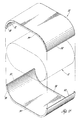
- the substrate is constructed with a stack of modules individually formed of folded metal foil having contacting layers defining passages therebetween.
- the modules are individually formed of folded and interleaved sheets of smooth and corrugated foil.
- the sheets have a single fold permitting their interleaving in a manner so that the halves of the corrugated sheet are arranged to alternate with the halves of the smooth sheet to form a row of passages between the adjacent foil layers.
- the modules are simply individually forced of a single corrugated sheet that has a zigzag or herringbone pattern of corrugations and is folded directly on itself a certain number of times to obtain the desired rows of passages.
- the substrate modules are provided with a uniform thickness and length but various widths so as to be stackable on each other and conformable to the curved cross-sectional outline or profile of the desired substrate cross-section. As such, their assembly is ideally suited for high speed production using simple shuttle type equipment.
- a sheet metal retainer comprising a pair of identical shells is provided for the stacked modules and conjointly exactly conform about their interior to the desired substrate cross-section profile whereas the free stack height of the modules is made oversize. A substantial compressive load is thus applied to the modules crosswise thereof by clamping action of the retainer shells when they are forced together and affixed along abutting longitudinal edges by welding.
- the stacked modules are thereafter frictionally held together with the thus retained compressive load which is determined so as to prevent relative sliding movement of the substrate foil layers under the harshest conditions expected to be experienced in the exhaust system environment.
- the retainer shells are provided with an inwardly projecting flange at their opposite ends which extends over the corners of the stacked modules to positively prevent any longitudinal movement between the substrate foil layers and the retainer.
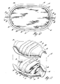
- the catalytic converter is particularly adapted with a low profile cross-section of oval shape for installation in an automobile exhaust system and generally comprises a housing 10 enclosing a retainer and monolith assembly 12 as best seen in Figures 1-3, 10 and 11.
- the housing 10 comprises a pair of identical sheet metal shells 14 having semi-cylindrical end sections 16 and an intermediately located semi-oval section 18.
- the housing shells' semi-oval sections 18 conjointly conform to the periphery of a monolith retainer 20 of assembly 12 so as to receive same in direct contact while the semicylindrical end sections 16 cooperate to define cylindrical inlet and outlet openings at opposite ends of a monolith 22 of assembly 12,adapting the converter for connection in an en g ine's exhaust pipe system (not shown).
- the housing shells 14 are formed midway of their oval section 18 with an internal semi-annular groove 24 which is adapted to receive a split ring seal 26 extending about the middle of the monolith retainer.
- the seal 26 is made of resilient heat expandable intumescent material such as that supplied under the tradename Interam by Technical Ceramics Products Division, 3M Company.
- the housing shells 14 are formed along their edge on each side with an outwardly projecting flange 28 extending from one end to the other so that when the housing shells are forced together about the retainer and monolith assembly 12 these flanges mate and then may be sealingly secured together to complete the converter assembly.
- the mating flanges 28 are initially held together by a plurality of spot welds 30 whereafter they are permanently fixed and sealed along their entire length by an edge weld 32.
- the retainer 20 comprises a pair of identical sheet metal shells 34 as best seen in Figures 2, 4 and 8 while the monolith or substrate 22 which is retained thereby as disclosed in more detail later, is constructed of metal foil modules 36.
- the modules 36 are individually formed of folded and interleaved sheets 38 and 40 of smooth and corrugated metal foil respectively.
- the two sheets 38 and 40 have a single fold 42 and 44 respectively permitting their interleaving in a manner so that the halves 46 of the smooth foil sheet alternate with the halves 48 of the corrugated foil sheet to form a row of straight-through passages 50 between the adjacent foil layers (i.e. two rows).
- the modules can be constructed in the form 36' shown in Figures 6 and 7 by simply individually forming them of a single sheet 40' of corrugated metal foil having a zigzag or herringbone pattern such as disclosed in U.S. Patent 4,318,88E assigned to the assignee of the present invention and which is hereby incorporated by reference.
- This permits folding of the sheet 40' directly on itself without nesting to form two rows of passages 50' with the same module thickness (T) as the Figure 5 module.
- the herringbone pattern of corrugations provides the passages 50' with multiple turns whose number and angular direction can be varied for better heat and mass transfer behavior with low pressure drop (i.e. better converter efficiency).
- the foil used in the construction of the modules 36 and 36' is whisker-covered metal foil which has been found to be ideally suited to retain a catalyst coating as disclosed in the afore-mentioned U.S. Patents 4,318,828 and 4,331,631 assigned to the assignee of the present invention and which are hereby incorporated by reference.
- the modules 36 or 36' are provided with a uniform thickness (T) and length (L) but various widths (W) so as to be stackable on each other as best seen in Figure 8 and conformable to the outline or profile of the desired substrate cross-section as seen in Figure 10.
- the two retainer shells 34 provided for the stacked modules conjointly exactly conform about their interior to the desired substrate cross-sectional profile whereas the free or unloaded stack height of the modules 36 or 36' is made oversize so that a predetermined compressive load is applied to the modules crosswise thereof by clamping action of the retainer shells when they are forced to engage each other on opposite sides along mating longitudinal edges 52 which then are permanently joined by seam welds 54.
- the stacked modules 36 or 36' are thereafter frictionally held together with the thus retained compressive load which is determined so as to prevent relative sliding movement of the substrate foil layers under the harshest conditions expected to be experienced in the exhaust system. And thus there is no need for any form of mechanical strengthening or bonding of the metal foil substrate layers.
- the module R as best seen in Figure 9, was formed of 0.051 mm flat sheet 60 and 1.12 mm transverse corrugated sheet 62 producing a module thickness (T) of 1.17 mm.
- T module thickness
- the retainer shells are provided with an inwardly projecting flange 58 at their opposite ends which extends over the corners of the stacked modules.
- the retainer and monolith assembly using the whisker-covered foil may be completely assembled and thereafter needs only to be coated with a suitable catalyst as a final step before being mounted in the converter housing.
- the retainer and monolith assembly serves as a subassembly or insert that mounts in a clam shell type housing, it is also contemplated that the retainer itself could serve as the converter housing with suitable inlet and outlet sections then secured to the opposite ends thereof so as to adapt the retainer and monolith assembly for installation in an exhaust system.
- the present invention readily lends itself to the formation of other cross-sectional forms having a curved profile.
- the present invention readily lends itself to the formation of other cross-sectional forms having a curved profile.
- W width
- T thickness
- a substrate having an irregular as well as a circular cross-sectional profile can be readily constructed.
- the pairings of the modules there is a commonality of parts which further simplifies the manufacture and assembly of the retainer and substrate assembly.
Abstract
Description
- This invention relates to catalytic converters and more particularly to those with a catalyst coated metal substrate of curved cross-sectional profile.
- In the manufacture of catalytic converters used to eliminate the undesirable constituents in combustion engine exhaust gases, it is currently common practice as an alternative to bedded ceramic beads to employ a ceramic monolith or substrate that is coated with a catalyst and contained in a sheet metal housing through which the exhaust gases are directed. The ceramic is both frangible and has a much lower coefficient of expansion than the sheet metal forming the housing and as a result, an arrangement is required that will both support and maintain sealed integrity of the ceramic monolith without fracture thereof in the harsh vibratory and temperature environment of the engine exhaust system. Moreover, the ceramic monolith is normally formed by extrusion through a die and as a result a new die is required for every cross-sectional change.
- Metal foil honeycomb substrates have been proposed in avoidance of such problems: however, they are typically deficient in some respect and/or present their own problems from a manufacturing and/or functional standpoint. For example, it is known to form the honeycomb substrate by spirally winding strips of smooth and corrugated metal foil but there results the problem of relative telescoping or sliding between the layers which abrades the catalyst. With such an arrangement, it is difficult to maintain the integrity of the metal substrate without some form of mechanical strengthening or bonding of the layers. Then there remains another major problem of allowing design flexibility in the shape of the metal layered substrate cross-section to meet various space allocations while maintaining a curved profile for housing strength reasons. This is particularly important in meeting certain vehicle underflow space requirements where a low profile cross-section of, for example, oval shape is desired instead of a circular one which requires a larger height for the same area. Moreover, there is the difficulty and expense of manufacture in completely forming a metal layered substrate so as to be suitable for a final step of applying the catalyst coating. For example, a whisker-covered metal foil has been developed that is ideally suited to retain a catalyst coating as disclosed in U.S. Patents 4,318,828 and 4,331,631 assigned to the assignee of the present invention. However, the whiskers on such foil are metal oxide growths and as a result, form both a metallurgical and mechanical barrier preventing intimate contact between the base metal of adjacent layers of the foil and thereby the strong fusion welding thereof which is normally necessary to form a suitable honeycomb substrate for the catalyst.
- The present invention solves such problems and is a substantial departure from the conventional method of winding foil to form the substrate. According to the present invention, the substrate is constructed with a stack of modules individually formed of folded metal foil having contacting layers defining passages therebetween. In one embodiment, the modules are individually formed of folded and interleaved sheets of smooth and corrugated foil. The sheets have a single fold permitting their interleaving in a manner so that the halves of the corrugated sheet are arranged to alternate with the halves of the smooth sheet to form a row of passages between the adjacent foil layers. In another embodiment, the modules are simply individually forced of a single corrugated sheet that has a zigzag or herringbone pattern of corrugations and is folded directly on itself a certain number of times to obtain the desired rows of passages.
- The substrate modules are provided with a uniform thickness and length but various widths so as to be stackable on each other and conformable to the curved cross-sectional outline or profile of the desired substrate cross-section. As such, their assembly is ideally suited for high speed production using simple shuttle type equipment. A sheet metal retainer comprising a pair of identical shells is provided for the stacked modules and conjointly exactly conform about their interior to the desired substrate cross-section profile whereas the free stack height of the modules is made oversize. A substantial compressive load is thus applied to the modules crosswise thereof by clamping action of the retainer shells when they are forced together and affixed along abutting longitudinal edges by welding. With such joining of the retainer shells, the stacked modules are thereafter frictionally held together with the thus retained compressive load which is determined so as to prevent relative sliding movement of the substrate foil layers under the harshest conditions expected to be experienced in the exhaust system environment. Moreover, the retainer shells are provided with an inwardly projecting flange at their opposite ends which extends over the corners of the stacked modules to positively prevent any longitudinal movement between the substrate foil layers and the retainer. Thus, it will be appreciated that the above novel arrangement permits use of the afore-mentioned whisker-covered foil without requiring welding together of the foil layers and the resulting containerized preloaded whisker-covered metal substrate need only be coated with a suitable catalyst as a final step before being mounted in a suitable converter housing or otherwise adapted for use.
- These and other objects, advantages and features of the present invention will become more apparent from the following description and drawings in which:
- Figure 1 is a plan view with parts broken away of a catalytic converter constructed according to the present invention.
- Figure 2 is a side elevation but with parts broken away of the converter in Figure 1.
- Figure 3 is an end elevation taken along the line 3-3 in Figure 1.
- Figure 4 is an exploded perspective view of a retainer in the converter in Figure 1.
- Figure 5 is an enlarged end view of one embodiment of modules forming a substrate in the converter in Figure 1.
- Figure 6 is an enlarged end view of another embodiment of the modules which may be used to form the substrate in the converter in Figure 1.
- Figure 7 is a plan view but with parts broken away taken along the line 7-7 in Figure 6.
- Figure 8 is an enlarged cross-sectional view showing the assembly of the substrate modules in Figure 5 in the retainer of Figure 4 with the top shell of the latter exploded.
- Figure 9 is an enlarged sectional view taken along the line 9-9 in Figure 8.
- Figure 10 is an enlarged cross-sectional view taken along the line 10-10 in Figure 1.
- Figure 11 is a perspective view of the converter in Figure 1 with the top housing shell exploded.
- Referring to the drawings, there is shown a catalytic converter constructed according to the present invention and intended for use in eliminating undesirable constituents in internal combustion engine exhaust gases. The catalytic converter is particularly adapted with a low profile cross-section of oval shape for installation in an automobile exhaust system and generally comprises a
housing 10 enclosing a retainer andmonolith assembly 12 as best seen in Figures 1-3, 10 and 11. Thehousing 10 comprises a pair of identicalsheet metal shells 14 havingsemi-cylindrical end sections 16 and an intermediately locatedsemi-oval section 18. The housing shells'semi-oval sections 18 conjointly conform to the periphery of amonolith retainer 20 ofassembly 12 so as to receive same in direct contact while thesemicylindrical end sections 16 cooperate to define cylindrical inlet and outlet openings at opposite ends of a monolith 22 ofassembly 12,adapting the converter for connection in an engine's exhaust pipe system (not shown). In addition, thehousing shells 14 are formed midway of theiroval section 18 with an internalsemi-annular groove 24 which is adapted to receive asplit ring seal 26 extending about the middle of the monolith retainer. Theseal 26 is made of resilient heat expandable intumescent material such as that supplied under the tradename Interam by Technical Ceramics Products Division, 3M Company. Thehousing shells 14 are formed along their edge on each side with an outwardly projectingflange 28 extending from one end to the other so that when the housing shells are forced together about the retainer andmonolith assembly 12 these flanges mate and then may be sealingly secured together to complete the converter assembly. For purposes of processing themating flanges 28 are initially held together by a plurality ofspot welds 30 whereafter they are permanently fixed and sealed along their entire length by anedge weld 32. - The
retainer 20 comprises a pair of identicalsheet metal shells 34 as best seen in Figures 2, 4 and 8 while the monolith or substrate 22 which is retained thereby as disclosed in more detail later, is constructed ofmetal foil modules 36. As best seen in Figure 5, themodules 36 are individually formed of folded and interleavedsheets sheets single fold 42 and 44 respectively permitting their interleaving in a manner so that the halves 46 of the smooth foil sheet alternate with the halves 48 of the corrugated foil sheet to form a row of straight-throughpassages 50 between the adjacent foil layers (i.e. two rows). Alternatively, the modules can be constructed in the form 36' shown in Figures 6 and 7 by simply individually forming them of a single sheet 40' of corrugated metal foil having a zigzag or herringbone pattern such as disclosed in U.S. Patent 4,318,88E assigned to the assignee of the present invention and which is hereby incorporated by reference. This permits folding of the sheet 40' directly on itself without nesting to form two rows of passages 50' with the same module thickness (T) as the Figure 5 module. Moreover, in the Figure 6 module construction, the herringbone pattern of corrugations provides the passages 50' with multiple turns whose number and angular direction can be varied for better heat and mass transfer behavior with low pressure drop (i.e. better converter efficiency). - Preferably, the foil used in the construction of the
modules 36 and 36' is whisker-covered metal foil which has been found to be ideally suited to retain a catalyst coating as disclosed in the afore-mentioned U.S. Patents 4,318,828 and 4,331,631 assigned to the assignee of the present invention and which are hereby incorporated by reference. - The
modules 36 or 36' are provided with a uniform thickness (T) and length (L) but various widths (W) so as to be stackable on each other as best seen in Figure 8 and conformable to the outline or profile of the desired substrate cross-section as seen in Figure 10. The tworetainer shells 34 provided for the stacked modules conjointly exactly conform about their interior to the desired substrate cross-sectional profile whereas the free or unloaded stack height of themodules 36 or 36' is made oversize so that a predetermined compressive load is applied to the modules crosswise thereof by clamping action of the retainer shells when they are forced to engage each other on opposite sides along matinglongitudinal edges 52 which then are permanently joined byseam welds 54. With such joining of the retainer shells, the stackedmodules 36 or 36' are thereafter frictionally held together with the thus retained compressive load which is determined so as to prevent relative sliding movement of the substrate foil layers under the harshest conditions expected to be experienced in the exhaust system. And thus there is no need for any form of mechanical strengthening or bonding of the metal foil substrate layers. - For example, in an actual construction of the converter shown having the
modules 36 with a thickness (T) of about 2.36 mm using 1.12 mm corrugated stock and 0.051mm flat or smooth stock and wherein the oval cross-sectional shape had a major axis length of about 147 mm, a minor axis length of about 76 mm and a length (L) in one case of about 90 mm and in another case of about 114 mm, it was determined that a compressive load of about 681-908 Kg. (1500-2000 pounds) proved satisfactory (i.e. did not crush the passages or exceed the modules of elasticity of the foil while maintaining desired retention under the harshest conditions). This result was produced with the stack of modules listed in the substrate layout chart below having reference to Figure 8 and alphabetical designation of the modules as - indicated:
- As seen in the above chart, this was accomplished primarily with pairings of equal width (A-0, A'-O') located on opposite sides of the major axis while two pairs of identical width modules P, P' and Q, Q' were used either side of a central relatively non-compliant corrugated spacer module 56(R) to gain the necessary oversize which in this case was determined to be about 5 mm or about 7%. For spacer purposes the module R as best seen in Figure 9, was formed of 0.051 mm
flat sheet 60 and 1.12 mm transverse corrugated sheet 62 producing a module thickness (T) of 1.17 mm. However, it will be understood that such spacer is not necessary to practicing the invention in that the thickness of themodules 36 and 36' can be varied to meet the desired oversize. Then as further prevention against relative movement of the substrate layers as well as to positively prevent movement thereof relative to the retainer, the retainer shells are provided with an inwardly projectingflange 58 at their opposite ends which extends over the corners of the stacked modules. - Thus it will be appreciated that the retainer and monolith assembly using the whisker-covered foil may be completely assembled and thereafter needs only to be coated with a suitable catalyst as a final step before being mounted in the converter housing. Moreover, while in the preferred construction shown the retainer and monolith assembly serves as a subassembly or insert that mounts in a clam shell type housing, it is also contemplated that the retainer itself could serve as the converter housing with suitable inlet and outlet sections then secured to the opposite ends thereof so as to adapt the retainer and monolith assembly for installation in an exhaust system.
- Furthermore, it will be appreciated while the catalytic converter shown has an oval cross-sectional profile, the present invention readily lends itself to the formation of other cross-sectional forms having a curved profile. For example, using the above stacking arrangement with either of the
module embodiments 36 or 36' and by simply varying the width (W) and/or thickness (T) of the modules and/or their number, it can be seen that a substrate having an irregular as well as a circular cross-sectional profile can be readily constructed. It will also be appreciated that with the pairings of the modules there is a commonality of parts which further simplifies the manufacture and assembly of the retainer and substrate assembly. - The above described preferred embodiments are thus illustrative of the invention which may be modified within the scope of the appended claims.
Claims (5)
Applications Claiming Priority (2)
| Application Number | Priority Date | Filing Date | Title |
|---|---|---|---|
| US06/470,159 US4559205A (en) | 1983-02-28 | 1983-02-28 | Catalytic converter substrate and retainer assembly |
| US470159 | 1983-02-28 |
Publications (3)
| Publication Number | Publication Date |
|---|---|
| EP0117602A2 true EP0117602A2 (en) | 1984-09-05 |
| EP0117602A3 EP0117602A3 (en) | 1987-01-14 |
| EP0117602B1 EP0117602B1 (en) | 1989-06-14 |
Family
ID=23866514
Family Applications (1)
| Application Number | Title | Priority Date | Filing Date |
|---|---|---|---|
| EP84300122A Expired EP0117602B1 (en) | 1983-02-28 | 1984-01-10 | Catalytic converter substrate |
Country Status (6)
| Country | Link |
|---|---|
| US (1) | US4559205A (en) |
| EP (1) | EP0117602B1 (en) |
| JP (1) | JPS59162317A (en) |
| AU (1) | AU567316B2 (en) |
| CA (1) | CA1213834A (en) |
| DE (1) | DE3478664D1 (en) |
Cited By (8)
| Publication number | Priority date | Publication date | Assignee | Title |
|---|---|---|---|---|
| EP0217493A1 (en) * | 1985-09-03 | 1987-04-08 | General Motors Corporation | Catalytic converter substrate |
| EP0278597A2 (en) * | 1987-02-13 | 1988-08-17 | General Motors Corporation | Mat support/substrate subassembly and method of making a catalytic converter therewith |
| EP0375986A1 (en) * | 1988-12-30 | 1990-07-04 | Emitec Gesellschaft für Emissionstechnologie mbH | Carrier for a catalytic reactor for the purification of exhaust gases |
| EP0419906A1 (en) * | 1989-09-12 | 1991-04-03 | W.R. Grace & Co.-Conn. | Core element and core for electrically heatable catalytic converter |
| EP0434539A1 (en) * | 1989-12-22 | 1991-06-26 | Etablissements Rosi | In particular catalytic exhaust system for the exhaust gases of an internal combustion engine |
| EP0705963A1 (en) * | 1994-09-12 | 1996-04-10 | Baildon, Huta | Apparatus for catalytic purification of exhaust gas from internal combustion engines |
| EP0761939A1 (en) * | 1995-08-16 | 1997-03-12 | General Motors Corporation | Manifold converter |
| US10598068B2 (en) | 2015-12-21 | 2020-03-24 | Emissol, Llc | Catalytic converters having non-linear flow channels |
Families Citing this family (34)
| Publication number | Priority date | Publication date | Assignee | Title |
|---|---|---|---|---|
| JPH0356253Y2 (en) * | 1985-02-05 | 1991-12-17 | ||
| US5482681A (en) * | 1985-09-20 | 1996-01-09 | Tennessee Gas Pipeline Company | Catalytic converter for motor vehicles |
| US4711009A (en) * | 1986-02-18 | 1987-12-08 | W. R. Grace & Co. | Process for making metal substrate catalytic converter cores |
| JPH0716014Y2 (en) * | 1986-06-02 | 1995-04-12 | トヨタ自動車株式会社 | Diagonal flow type catalyst converter |
| JPH0621558B2 (en) * | 1986-08-25 | 1994-03-23 | カルソニック株式会社 | Metal honeycomb carrier |
| JPH0730892Y2 (en) * | 1987-07-27 | 1995-07-19 | 日産自動車株式会社 | Metal honeycomb catalyst converter |
| GB2207615B (en) * | 1987-07-31 | 1991-06-19 | Tenneco Inc | Catalytic converter and substrate support |
| US5119551A (en) * | 1989-02-06 | 1992-06-09 | Tennessee Gas Pipeline Company | Method of making a catalytic converter with one piece housing |
| US5051294A (en) * | 1989-05-15 | 1991-09-24 | General Motors Corporation | Catalytic converter substrate and assembly |
| US5187334A (en) * | 1990-07-02 | 1993-02-16 | Tennessee Gas Pipeline Company | Acoustic muffler with one-piece housing |
| US5216809A (en) * | 1990-07-02 | 1993-06-08 | Tennessee Gas Pipeline Company | Acoustic muffler with one-piece housing |
| DE4041856A1 (en) * | 1990-12-24 | 1992-06-25 | Behr Gmbh & Co | DEVICE FOR THE CATALYTIC DETOXIFICATION OF EXHAUST GAS, PREFERREDLY FROM COMBUSTION ENGINES |
| US5187142A (en) * | 1991-09-03 | 1993-02-16 | General Motors Corporation | Catalytic converter metal monolith |
| JP3222542B2 (en) * | 1992-04-24 | 2001-10-29 | 株式会社デンソー | Metal catalyst carrier |
| US5330728A (en) * | 1992-11-13 | 1994-07-19 | General Motors Corporation | Catalytic converter with angled inlet face |
| US5960529A (en) * | 1994-11-07 | 1999-10-05 | Emitec Gessellschaft Fuer Emissionstechnologie Mbh | Apparatus and method for deforming a jacket tube of a honeycomb body |
| US5575980A (en) * | 1995-08-14 | 1996-11-19 | General Motors Corporation | Valved radial flow catalytic converter |
| US5937516A (en) * | 1996-12-13 | 1999-08-17 | General Motors Corporation | Method for spin forming articles |
| US5958603A (en) * | 1997-06-09 | 1999-09-28 | Atd Corporation | Shaped multilayer metal foil shield structures and method of making |
| US5939212A (en) | 1997-06-09 | 1999-08-17 | Atd Corporation | Flexible corrugated multilayer metal foil shields and method of making |
| MXPA99011565A (en) | 1997-06-09 | 2004-09-01 | Atd Corp | Shaped multilayer metal foil shield structures and method of making. |
| PT1094740E (en) | 1998-07-09 | 2005-03-31 | Atd Corp | PORTABLE GAS GRAVEL |
| US6099809A (en) * | 1998-08-31 | 2000-08-08 | General Motors Corporation | Catalytic converter having a metal foil substrate |
| US6497847B2 (en) | 1998-10-26 | 2002-12-24 | Delphi Technologies, Inc. | Catalytic converter end plate inlet/outlet plenum length ratio |
| US6185820B1 (en) | 1998-10-26 | 2001-02-13 | General Motors Corporation | Reduced cost substrate retaining mat |
| US20020146354A1 (en) * | 2001-04-10 | 2002-10-10 | Hsin-Hong Huang | Hydroform dual-wall catalytic converter |
| DE10153283A1 (en) * | 2001-10-29 | 2003-05-15 | Emitec Emissionstechnologie | Heat-resistant filter layer, filter body and process for its production |
| US7587819B1 (en) | 2002-12-23 | 2009-09-15 | Hall Jr Herbert L | Insert for a catalytic converter and method and apparatus for forming an insert for a catalytic converter |
| DE202004000659U1 (en) * | 2004-01-17 | 2004-04-15 | Heinrich Gillet Gmbh | Silencers for motor vehicles with internal combustion engines |
| DE102004059381A1 (en) * | 2004-12-09 | 2006-06-22 | Arvinmeritor Emissions Technologies Gmbh | Housing for a component of an exhaust system |
| CN102575554B (en) * | 2009-10-28 | 2016-04-20 | 赫多特普索化工设备公司 | The method of purification of engine exhaust gas and device |
| JP5917919B2 (en) * | 2012-01-16 | 2016-05-18 | 本田技研工業株式会社 | Support structure of honeycomb carrier |
| USD786935S1 (en) | 2015-11-20 | 2017-05-16 | Baldwin Filters, Inc. | Filter element |
| US10436094B2 (en) | 2017-01-30 | 2019-10-08 | Acat Global | Swaged shell |
Citations (3)
| Publication number | Priority date | Publication date | Assignee | Title |
|---|---|---|---|---|
| FR2321591A1 (en) * | 1975-08-18 | 1977-03-18 | Honda Motor Co Ltd | REACTOR FOR EXHAUST SYSTEM OF INTERNAL COMBUSTION ENGINE AND ENGINE EQUIPPED WITH REACTOR |
| DE2856030A1 (en) * | 1978-12-23 | 1980-06-26 | Sueddeutsche Kuehler Behr | CARTRIDGE FOR EXHAUST GAS PURIFICATION |
| US4331631A (en) * | 1979-11-28 | 1982-05-25 | General Motors Corporation | Enhanced oxide whisker growth on peeled Al-containing stainless steel foil |
Family Cites Families (18)
| Publication number | Priority date | Publication date | Assignee | Title |
|---|---|---|---|---|
| US30629A (en) * | 1860-11-13 | Baileoad-joint | ||
| US3088271A (en) * | 1961-02-06 | 1963-05-07 | Minnesota Mining & Mfg | Reaction milieu and afterburner incorporating same |
| US3227659A (en) * | 1962-06-28 | 1966-01-04 | Texaco Inc | Treatment of exhaust gases using an alumina base alkali metal phosphorus-containing compound |
| US3441381A (en) * | 1965-06-22 | 1969-04-29 | Engelhard Ind Inc | Apparatus for purifying exhaust gases of an internal combustion engine |
| US3787944A (en) * | 1971-09-20 | 1974-01-29 | Ford Motor Co | Method of assembling a gas turbine regenerator assembly |
| US3785781A (en) * | 1971-10-04 | 1974-01-15 | Universal Oil Prod Co | Apparatus for catalytically converting fluid |
| DE2243251B2 (en) * | 1972-09-02 | 1976-01-02 | Paul Gillet Gmbh, 6732 Edenkoben | Device for cleaning exhaust gases from internal combustion engines |
| DE2302746A1 (en) * | 1973-01-20 | 1974-07-25 | Sueddeutsche Kuehler Behr | CARRIER MATRIX FOR A CATALYTIC REACTOR FOR EXHAUST GAS CLEANING IN COMBUSTION MACHINES, ESPEC. GASOLINE ENGINES OF MOTOR VEHICLES AND A MANUFACTURING PROCESS |
| US4182120A (en) * | 1973-03-20 | 1980-01-08 | Ethyl Corporation | Exhaust systems |
| US3830286A (en) * | 1973-03-29 | 1974-08-20 | Stalker Corp | Heat exchanger core and method of fabrication thereof |
| US4078898A (en) * | 1974-02-11 | 1978-03-14 | Gould Inc. | Catalyst-coated expanded metal foil substrate for an exhaust gas reactor |
| GB1500702A (en) | 1974-03-26 | 1978-02-08 | Rolls Royce | Heat engine |
| JPS5516395Y2 (en) * | 1975-08-29 | 1980-04-16 | ||
| US3996997A (en) * | 1975-12-22 | 1976-12-14 | Combustion Engineering, Inc. | Tightening of heating elements of a regenerative air heater |
| CA1102706A (en) * | 1977-05-06 | 1981-06-09 | Rainer Scholz | Monolithic metal catalyst for the detoxication of the exhaust gases of internal combustion engines |
| US4335078A (en) * | 1977-09-13 | 1982-06-15 | Nissan Motor Company, Limited | Catalytic reactor for automotive exhaust line |
| JPS6035523B2 (en) * | 1980-03-12 | 1985-08-15 | 本田技研工業株式会社 | Catalyst carrier support device |
| US4318888A (en) * | 1980-07-10 | 1982-03-09 | General Motors Corporation | Wound foil structure comprising distinct catalysts |
-
1983
- 1983-02-28 US US06/470,159 patent/US4559205A/en not_active Expired - Fee Related
- 1983-10-03 CA CA000438197A patent/CA1213834A/en not_active Expired
-
1984
- 1984-01-10 EP EP84300122A patent/EP0117602B1/en not_active Expired
- 1984-01-10 DE DE8484300122T patent/DE3478664D1/en not_active Expired
- 1984-01-18 AU AU23570/84A patent/AU567316B2/en not_active Ceased
- 1984-02-28 JP JP59035483A patent/JPS59162317A/en active Granted
Patent Citations (3)
| Publication number | Priority date | Publication date | Assignee | Title |
|---|---|---|---|---|
| FR2321591A1 (en) * | 1975-08-18 | 1977-03-18 | Honda Motor Co Ltd | REACTOR FOR EXHAUST SYSTEM OF INTERNAL COMBUSTION ENGINE AND ENGINE EQUIPPED WITH REACTOR |
| DE2856030A1 (en) * | 1978-12-23 | 1980-06-26 | Sueddeutsche Kuehler Behr | CARTRIDGE FOR EXHAUST GAS PURIFICATION |
| US4331631A (en) * | 1979-11-28 | 1982-05-25 | General Motors Corporation | Enhanced oxide whisker growth on peeled Al-containing stainless steel foil |
Cited By (12)
| Publication number | Priority date | Publication date | Assignee | Title |
|---|---|---|---|---|
| EP0217493A1 (en) * | 1985-09-03 | 1987-04-08 | General Motors Corporation | Catalytic converter substrate |
| EP0278597A2 (en) * | 1987-02-13 | 1988-08-17 | General Motors Corporation | Mat support/substrate subassembly and method of making a catalytic converter therewith |
| EP0278597A3 (en) * | 1987-02-13 | 1990-01-10 | General Motors Corporation | Mat support/substrate subassembly and method of making a catalytic converter therewith |
| EP0375986A1 (en) * | 1988-12-30 | 1990-07-04 | Emitec Gesellschaft für Emissionstechnologie mbH | Carrier for a catalytic reactor for the purification of exhaust gases |
| EP0419906A1 (en) * | 1989-09-12 | 1991-04-03 | W.R. Grace & Co.-Conn. | Core element and core for electrically heatable catalytic converter |
| EP0434539A1 (en) * | 1989-12-22 | 1991-06-26 | Etablissements Rosi | In particular catalytic exhaust system for the exhaust gases of an internal combustion engine |
| FR2656376A1 (en) * | 1989-12-22 | 1991-06-28 | Rosi Ets | EXHAUST, ESPECIALLY CATALYTIC, FOR BURNED GASES FROM INTERNAL COMBUSTION ENGINES. |
| EP0705963A1 (en) * | 1994-09-12 | 1996-04-10 | Baildon, Huta | Apparatus for catalytic purification of exhaust gas from internal combustion engines |
| EP0761939A1 (en) * | 1995-08-16 | 1997-03-12 | General Motors Corporation | Manifold converter |
| US6605259B1 (en) | 1995-08-16 | 2003-08-12 | Delphi Technologies, Inc. | Manifold converter |
| US10598068B2 (en) | 2015-12-21 | 2020-03-24 | Emissol, Llc | Catalytic converters having non-linear flow channels |
| US10815856B2 (en) | 2015-12-21 | 2020-10-27 | Mansour Masoudi | Catalytic converters having non-linear flow channels |
Also Published As
| Publication number | Publication date |
|---|---|
| US4559205A (en) | 1985-12-17 |
| EP0117602A3 (en) | 1987-01-14 |
| JPS59162317A (en) | 1984-09-13 |
| AU2357084A (en) | 1984-09-06 |
| AU567316B2 (en) | 1987-11-19 |
| CA1213834A (en) | 1986-11-12 |
| EP0117602B1 (en) | 1989-06-14 |
| DE3478664D1 (en) | 1989-07-20 |
| JPH0250290B2 (en) | 1990-11-01 |
Similar Documents
| Publication | Publication Date | Title |
|---|---|---|
| EP0117602A2 (en) | Catalytic converter substrate | |
| US4619912A (en) | Catalytic converter substrate | |
| EP0486276B1 (en) | Carrier for automobile exhaust gas purifying catalyst | |
| KR920009120B1 (en) | Matallic carrier base for carrying exhaust gas purifying catalyst | |
| US4782661A (en) | Mat support/substrate subassembly and method of making a catalytic converter therewith | |
| US4750251A (en) | Mat support/substrate subassembly and method of making a catalytic converter therewith | |
| US3100140A (en) | Catalytic automotive exhaust converter | |
| US5084361A (en) | Heat resistant structure | |
| EP0858367B1 (en) | Carrier body for exhaust gas catalysts | |
| JPH0542300B2 (en) | ||
| US5380501A (en) | Exhaust gas cleaning device | |
| KR100581469B1 (en) | Monolithic honeycomb bodies and method for manufacturing the same | |
| US5336472A (en) | Honeycomb structure for purifying exhaust gas and method of manufacturing same | |
| EP0933131B1 (en) | Metal thin film for metal catalyst carrier and metal catalyst converter employing the metal thin film | |
| JP3913271B2 (en) | Catalytic converter configuration with two or more exhaust inductions | |
| JPH10280949A (en) | Metallic catalyst carrier of catalytic converter for internal combustion engine | |
| KR910008726B1 (en) | Catalyst support for catalytic reactors | |
| KR100495383B1 (en) | Catalytic converter for a small-size engine and method for manufacturing the same | |
| GB2174615A (en) | Matrix for a catalytic reactor for waste gas cleaning | |
| KR20000070873A (en) | Honeycomb body with cross-sectional area framed in the interior, particularly for small-power motors | |
| GB2047557A (en) | Catalyst assembly for exhaust systems | |
| EP1230978A1 (en) | Corrugated metal reactor packing and manufacturing method thereof | |
| JPH0443702B2 (en) | ||
| EP0613997A1 (en) | Catalyst carrier body in exhaust gas cleaning system and manufacturing method of the carrier body | |
| JP3454018B2 (en) | Structure of metal catalyst support |
Legal Events
| Date | Code | Title | Description |
|---|---|---|---|
| PUAI | Public reference made under article 153(3) epc to a published international application that has entered the european phase |
Free format text: ORIGINAL CODE: 0009012 |
|
| AK | Designated contracting states |
Designated state(s): DE FR GB IT SE |
|
| PUAL | Search report despatched |
Free format text: ORIGINAL CODE: 0009013 |
|
| AK | Designated contracting states |
Kind code of ref document: A3 Designated state(s): DE FR GB IT SE |
|
| 17P | Request for examination filed |
Effective date: 19870428 |
|
| 17Q | First examination report despatched |
Effective date: 19880222 |
|
| ITF | It: translation for a ep patent filed |
Owner name: BARZANO' E ZANARDO ROMA S.P.A. |
|
| GRAA | (expected) grant |
Free format text: ORIGINAL CODE: 0009210 |
|
| AK | Designated contracting states |
Kind code of ref document: B1 Designated state(s): DE FR GB IT SE |
|
| REF | Corresponds to: |
Ref document number: 3478664 Country of ref document: DE Date of ref document: 19890720 |
|
| ET | Fr: translation filed | ||
| PLBE | No opposition filed within time limit |
Free format text: ORIGINAL CODE: 0009261 |
|
| STAA | Information on the status of an ep patent application or granted ep patent |
Free format text: STATUS: NO OPPOSITION FILED WITHIN TIME LIMIT |
|
| 26N | No opposition filed | ||
| ITTA | It: last paid annual fee | ||
| PGFP | Annual fee paid to national office [announced via postgrant information from national office to epo] |
Ref country code: SE Payment date: 19950119 Year of fee payment: 12 |
|
| EAL | Se: european patent in force in sweden |
Ref document number: 84300122.3 |
|
| PG25 | Lapsed in a contracting state [announced via postgrant information from national office to epo] |
Ref country code: SE Effective date: 19960111 |
|
| EUG | Se: european patent has lapsed |
Ref document number: 84300122.3 |
|
| PGFP | Annual fee paid to national office [announced via postgrant information from national office to epo] |
Ref country code: GB Payment date: 19961216 Year of fee payment: 14 |
|
| PGFP | Annual fee paid to national office [announced via postgrant information from national office to epo] |
Ref country code: FR Payment date: 19970129 Year of fee payment: 14 |
|
| PGFP | Annual fee paid to national office [announced via postgrant information from national office to epo] |
Ref country code: DE Payment date: 19970227 Year of fee payment: 14 |
|
| PG25 | Lapsed in a contracting state [announced via postgrant information from national office to epo] |
Ref country code: GB Free format text: LAPSE BECAUSE OF NON-PAYMENT OF DUE FEES Effective date: 19980110 |
|
| PG25 | Lapsed in a contracting state [announced via postgrant information from national office to epo] |
Ref country code: FR Free format text: THE PATENT HAS BEEN ANNULLED BY A DECISION OF A NATIONAL AUTHORITY Effective date: 19980131 |
|
| GBPC | Gb: european patent ceased through non-payment of renewal fee |
Effective date: 19980110 |
|
| PG25 | Lapsed in a contracting state [announced via postgrant information from national office to epo] |
Ref country code: DE Free format text: LAPSE BECAUSE OF NON-PAYMENT OF DUE FEES Effective date: 19981001 |
|
| REG | Reference to a national code |
Ref country code: FR Ref legal event code: ST |