EP0117699A2 - Gas mixing & flow smoothing apparatus - Google Patents
Gas mixing & flow smoothing apparatus Download PDFInfo
- Publication number
- EP0117699A2 EP0117699A2 EP19840301083 EP84301083A EP0117699A2 EP 0117699 A2 EP0117699 A2 EP 0117699A2 EP 19840301083 EP19840301083 EP 19840301083 EP 84301083 A EP84301083 A EP 84301083A EP 0117699 A2 EP0117699 A2 EP 0117699A2
- Authority
- EP
- European Patent Office
- Prior art keywords
- gases
- chamber
- mixing chamber
- valve
- flow
- Prior art date
- Legal status (The legal status is an assumption and is not a legal conclusion. Google has not performed a legal analysis and makes no representation as to the accuracy of the status listed.)
- Withdrawn
Links
Images


Classifications
-
- A—HUMAN NECESSITIES
- A61—MEDICAL OR VETERINARY SCIENCE; HYGIENE
- A61M—DEVICES FOR INTRODUCING MEDIA INTO, OR ONTO, THE BODY; DEVICES FOR TRANSDUCING BODY MEDIA OR FOR TAKING MEDIA FROM THE BODY; DEVICES FOR PRODUCING OR ENDING SLEEP OR STUPOR
- A61M16/00—Devices for influencing the respiratory system of patients by gas treatment, e.g. mouth-to-mouth respiration; Tracheal tubes
- A61M16/10—Preparation of respiratory gases or vapours
- A61M16/12—Preparation of respiratory gases or vapours by mixing different gases
-
- A—HUMAN NECESSITIES
- A61—MEDICAL OR VETERINARY SCIENCE; HYGIENE
- A61M—DEVICES FOR INTRODUCING MEDIA INTO, OR ONTO, THE BODY; DEVICES FOR TRANSDUCING BODY MEDIA OR FOR TAKING MEDIA FROM THE BODY; DEVICES FOR PRODUCING OR ENDING SLEEP OR STUPOR
- A61M16/00—Devices for influencing the respiratory system of patients by gas treatment, e.g. mouth-to-mouth respiration; Tracheal tubes
- A61M16/20—Valves specially adapted to medical respiratory devices
- A61M16/201—Controlled valves
- A61M16/202—Controlled valves electrically actuated
-
- A—HUMAN NECESSITIES
- A61—MEDICAL OR VETERINARY SCIENCE; HYGIENE
- A61M—DEVICES FOR INTRODUCING MEDIA INTO, OR ONTO, THE BODY; DEVICES FOR TRANSDUCING BODY MEDIA OR FOR TAKING MEDIA FROM THE BODY; DEVICES FOR PRODUCING OR ENDING SLEEP OR STUPOR
- A61M16/00—Devices for influencing the respiratory system of patients by gas treatment, e.g. mouth-to-mouth respiration; Tracheal tubes
- A61M16/20—Valves specially adapted to medical respiratory devices
- A61M16/208—Non-controlled one-way valves, e.g. exhalation, check, pop-off non-rebreathing valves
- A61M16/209—Relief valves
-
- Y—GENERAL TAGGING OF NEW TECHNOLOGICAL DEVELOPMENTS; GENERAL TAGGING OF CROSS-SECTIONAL TECHNOLOGIES SPANNING OVER SEVERAL SECTIONS OF THE IPC; TECHNICAL SUBJECTS COVERED BY FORMER USPC CROSS-REFERENCE ART COLLECTIONS [XRACs] AND DIGESTS
- Y10—TECHNICAL SUBJECTS COVERED BY FORMER USPC
- Y10T—TECHNICAL SUBJECTS COVERED BY FORMER US CLASSIFICATION
- Y10T137/00—Fluid handling
- Y10T137/8593—Systems
- Y10T137/87571—Multiple inlet with single outlet
- Y10T137/87652—With means to promote mixing or combining of plural fluids
-
- Y—GENERAL TAGGING OF NEW TECHNOLOGICAL DEVELOPMENTS; GENERAL TAGGING OF CROSS-SECTIONAL TECHNOLOGIES SPANNING OVER SEVERAL SECTIONS OF THE IPC; TECHNICAL SUBJECTS COVERED BY FORMER USPC CROSS-REFERENCE ART COLLECTIONS [XRACs] AND DIGESTS
- Y10—TECHNICAL SUBJECTS COVERED BY FORMER USPC
- Y10T—TECHNICAL SUBJECTS COVERED BY FORMER US CLASSIFICATION
- Y10T137/00—Fluid handling
- Y10T137/8593—Systems
- Y10T137/87571—Multiple inlet with single outlet
- Y10T137/87676—With flow control
- Y10T137/87684—Valve in each inlet
Definitions
- This invention relates to apparatus for the mixing and smoothing of gas flows and is particularly concerned with apparatus adapted to produce a smooth and regulated flow of two or more mixed gases for use in the medical field of anaesthesia apparatus.
- a patient is supplied with a mixture of at least two gases, for example, oxygen and air or nitrous oxide, the mixed gases being dosed with vapourised anaesthetic drugs.
- gases for example, oxygen and air or nitrous oxide
- vapourised anaesthetic drugs vapourised anaesthetic drugs.
- it is essential that the proportions of the various gases in the mixture supplied to the patient are precisely regulated and furthermore a particularly smooth overall flow is required.
- It has been proposed to control the relative proportions of the constituent gases by means of a pulsed control valve in the supply line of each gas, the frequency or period of the valve pulses regulating the flow rate of the gas.
- Such an arrangement is advantageous in that the proportions of the gases may be set very accurately within a wide range of possible values.
- the pulsed valves being solenoid controlled, are inherently suitable for use with electronic control circuitry.
- the invention provides apparatus for mixing and smoothing the flow of two or more gases, comprising a mixing chamber with at least two inlet ducts and an outlet duct, the mixing chamber being adapted to absorb fluctuations in the pressure of the gases therein, and a valve connected downstream of the chamber adapted to maintain a substantially constant pressure at said chamber outlet duct.
- the series arrangement of a mixing chamber which acts as a surge damper and a substantially constant back pressure valve is such that any fluctuations in the flow of the inlet gases are attenuated and a substantially smooth flow of the mixed gases may be obtained from an outlet of the back pressure valve.
- Apparatus in accordance with the invention is therefore particularly suitable for mixing and smoothing regulated flows of different gases produced by pulsed control valves in an anaesthesia system.
- the mixing chamber is cylindrical in shape, and the inlet ducts are arranged such that the gases enter the chamber tangentially in opposite directions.
- the inlet flows tend to produce toroidal currents within the chamber which are in opposed senses, and this increases the efficiency of the mixing of the gases therefore minimising instantaneous variations in the relative proportions of the constituent gases in the outlet flow.
- the mixing chamber is preferably adapted to absorb fluctuations in gas pressure through the provision of a spring loaded piston which defines one wall of the chamber and which is outwardly displaceable in response to increases in gas pressure within the chamber.
- Sealing means for the piston may take any convenient form, for example sliding O-rings disposed between the piston and the chamber wall.
- the gas pressure may act on the piston through a flexible rolling diaphragm seal which is secured across the chamber adjacent to the piston and prevents gases escaping around the periphery of the piston.
- the constant back pressure valve is a variable orifice valve adapted to produce a substantially constant back pressure over a wide range of gas flow rates.
- a required operational gas pressure within the mixing chamber for efficient flow smoothing is maintained over a wide range of flow rates, and this is particularly important in an anaesthesia system where the required total flow of gases delivered to a patient might vary considerably.
- a preferred embodiment of back pressure valve includes a gravity loaded plunger or float slidably mounted in a vertically disposed tapered passage. In use the flow of mixed gases from the mixing chamber outlet is passed upwardly through the passage such that the plunger is forced upwardly until an equilibrium position is reached where the back pressure is equal to the weight of the plunger assembly.
- the plunger includes angled slots or channels around its periphery such that the passage of gas produces a rotational torque on the plunger.
- the resulting rotation of the plunger reduces the influence of friction and mechanical shock within the valve.
- a preferred embodiment of back pressure valve has been found to produce a substantially constant back pressure over flow rates varying between two and eighteen litres per minute.
- the apparatus may include a second surge damper and constant back pressure valve arranged in series downstream of the first constant back pressure valve.
- the second surge damper may be of similar construction to the mixing chamber and thus preferably comprises an enclosed cylindrical chamber one wall of which is defined by a spring loaded damping piston.
- the mixing chamber and second surge damper are secured together in back-to-back relationship with a central connecting plate disposed therebetween.
- the gases may conveniently be transmitted to and from the chambers via conduits formed in the connecting plate.
- the back-to-back configuration of the two cylindrical chambers provides a particularly compact unit.
- the overall attenuation of a variable or pulsed flow is greatly increased through the use of two surge damper and back pressure valve combinations arranged in series. If for example the attenuation factor of each combination is 80%, then the first combination would transmit to the second combination 20% of any pulse entering the apparatus; the second combination however would reduce this transmission to 20% of 20%, that is 4% of the original pulse at the inlet.
- a preferred embodiment of the invention includes a metering device for measuring the flow.
- the preferred form of constant back pressure value discussed above may conveniently be adapted for flow measurement, since the vertical displacement of the float or plunger thereof is related to the flow rate.
- a ferromagnetic rod is secured to and extends upwardly of the plunger assembly and is movable therewith. Displacement is measured by means of an assembly of inductance coils which surround the rod, changes in inductance being indicative of vertical movements of the plunger. Where fluctuating flows occur through the valve, an integral value of inductance may be obtained such that the average flow rate over a certain period of time is measured. This reduces the possibility of errors arising due to, for example, the plunger sticking within the passage.
- the preferred form of flow meter is particularly suitable for use with electronic control circuitry adapted continuously to monitor the gas flow rate through the apparatus.
- the invention provides a method of mixing and smoothing the flow of two or more gases comprising introducing the gases into an enclosed mixing chamber, the mixing chamber being adapted to absorb fluctuations in the pressure of the gases therein, and passing the mixed gases through a valve located downstream of the mixing chamber adapted to maintain a subtantially constant pressure at the outlet of said chamber.
- the apparatus and method in accordance with the first and second aspects of the invention are particularly suited for the supply of mixed gases to a patient in an anaesthesia system.
- the invention provides gas supply apparatus for an anaesthesia system comprising two or more pulsed valves adapted to produce regulated flows of two or more gases, a mixing chamber downstream of the valves in which the gases are mixed, surge damper means and back pressure valve means for attenuating pulses in the mixed gas flow, means for directing a controlled proportion of the total gas flow to anaesthetic drug dosing means, and a second mixing chamber for remixing the dosed gases with the main gas flow.
- the outlet orifices or jets of the pulsed valves are mounted so as to be in good thermal communication with one another. This is important to minimise the effect of relative thermal expansion or contraction of the orifices which can render the relative flow rates of the two gases inaccurate. This problem is significant where only a small percentage of one gas is required and thus the cooling effect resulting from the gas flow through one valve is very much less than that occuring from the gas flow through the other valve.
- the valve jets may conveniently be disposed in suitable orifices formed in the common connecting plate between the two cylinders.
- the various components of the system are arranged on a common mounting plate or tray thus forming a compact unit.
- the system lends itself to electronic control and monitoring by a microprocessor.
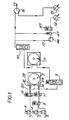
- gas supply apparatus for an anaesthesia system includes three inlet ducts 1, 2, 3 which in use are connected respectively to pressurised supplies of oxygen, nitrous oxide and air at pressures in the order of 60 p.s.i.
- the inlets 1,2,3 lead via pressure regulating valves 4 and solenoid controlled valves 5,6,7 to a mixing and flow smoothing apparatus comprising a combined mixing chamber and surge damper 8, two constant back pressure valves 9,10 and a second surge damper, all arranged in series as shown.
- a controlled proportion of the gas flow is directed in a manner to be described via a line 12 to a selector valve 14 which in use is connected to a number of vapourisers (not shown) for dosing the mixed gases with appropriate anaesthetic drugs.
- a selector valve 15 receives the dosed gases which are returned to the main flow via a line 3 and a second mixing chamber 16. The anaesthetic gases for supply to a patient leave the chamber 16 via an outlet duct 17.
- oxygen from the inlet 1 is mixed with either air or nitrous oxide, although clearly additional inlets might be provided for alternative gases.
- the solenoid controlled valve 5 selects whether nitrous oxide from the inlet 2 or air from the inlet 3 enters the system.
- the solenoid controlled valves 6 and 7 are pulsed metering valves adapted to regulate precisely the flow rates of the gases to required mean values such that the quantity of each gas supplied to a patient is accurately controlled.
- the gas pressure upstream of the valves 6, 7 is held constant by the regulating valves 4, and the flow rates through the metering valves 6,7 is therefore dependent upon the duration of the open periods of the valves 6,7.
- control circuitry for the apparatus includes means for generating a high frequency fundamental signal and the open pulses of each valve consist of an integral multiple of the period of this signal. In this way the length of the open periods of the valves 6,7 and thus the flow rates may be incrementally varied with a high degree of accuracy.
- the metering valves 6,7 produce pulsed gas flows which are introduced into the combined mixing chamber and surge damper 8 via respective valve nozzles or jets 18 having small orifices which may be adjustable to compensate for differences in density and viscosity of the gases such that the same volume of each gas is passed for a given open period of either valve 6,7.
- the size of the jet orifices may be fixed and gas density and viscosity differences may be compensated for by adjusting the pressure regulating valves 4.
- the jets 18 are mounted within a common metal plate and are therefore in mutual thermal contact. Thus relative temperature variations of the jets due to different gas flow rates therethrough are minimised.
- the chamber includes a cylindrical housing 19 closed at one end by a connecting plate 20 and at the other end by an end plate 21 including an aperture 22 open to the atmosphere.
- the end plate 21 mounts a piston 23 which is movable against the action of two coil springs 24,25 between the two extreme positions illustrated in Figure 2.
- the front face of the piston 23 defines a side wall of an enclosed mixing chamber 26.
- a perfect seal is ensured by a flexible rolling diaphragm 27 which is secured across the interior of the cylinder 19 and overlies the piston.
- Formed in the connecting plate 20 are two inlet orifices 28,29 through which the gases to be mixed are introduced into the chamber 26, and a centrally disposed outlet orifice.
- the jets of the pulsed metering valves 6,7 may conveniently be disposed in enlarged end portions 31 of the inlet orifices 28,29 thereby ensuring mutual thermal contact therebetween. It will be seen that the orifices 28,29 are arranged tangentially and that the two gas flows into the chamber 26 will tend to produce circulating currents in opposite directions; this promotes efficient mixing of the two gases and thus reduces the possibility of instantaneous variations in the relative concentrations of the constituent gases.
- the outlet 30 is connected to the valve 9 which is adapted to maintain a substantially constant back pressure over a wide range of flow rates in a manner to be described.
- the spring loaded piston 23 acts as a surge damper which absorbs increases in gas pressure within the chamber 26 owing to the pulsed inlet flow and thus the series combination of chamber and back pressure valve constitutes a mechanical resistance and compliance effective to attenuate the pulses and smooth the gas flow. Such a combination may provide an attenuation factor in the order of 80%.
- a second surge damper 11 and back pressure valve 20 are located downstream of the first.
- the surge damper 11 is of similar construction to the combined mixing chamber and surge damper 8, and is mounted in back-to-back relationship therewith to the connecting plate 20.
- the surge damper 11 includes a damping piston and rolling diaphragm which although not shown in Figure 2 are similar to the piston 23 and diaphragm 27 of the combined mixing chamber and surge damper 8.
- the surge damper 11 includes only a single inlet 31 and an outlet 32 which are again formed as bores in the common connecting plate 20. It should be noted that the gas pressure in the combined mixer and surge damper 8 will be twice that in the surge damper 11, since the effects of the valves 9 and 10 are additive. Therefore in order to match the surge damper 11 to the operating pressure, the piston thereof is biased by only a single coil spring of similar rate to springs 24,25.
- the valve 9 includes an inlet 33 and an outlet 34 connected by a vertical tapered passage 35 defined by a housing 36. Slidably mounted in the passage 35 is a plunger 37 secured to a shaft 37. The shaft 37 mounts at its lower end a weight 38 which is disposed in a closed chamber 39 in a housing 37 below the passage 35. A bush 40 locates the upper portion of the shaft 38, the bush being provided with gas flow apertures 41. Gas flowing though the passage 35 urges the plunger 37 upwardly until the difference in pressure between the gas below and above the plunger is equal to the pressure resulting from the weight of the plunger and weight assembly.
- the valve 9 further comprises a flow metering device located in a housing 42 secured to the top of the housing 36.
- the plunger shaft 38 mounts a ferromagnetic stem 43 which extends upwardly through an assembly of coils 44. Measurements of the inductance between the coils are indicative of the vertical displacement of the plunger and therefore the gas flow rate through the valve 9. Measurements are made by applying current to a central one of the coils 44 and measuring the current induced in the other coils.
- the metering device is included in the upstream rather than the downstream back pressure valve since the flow upstream of the second surge damper 11 is still fluctuating to a degree. This enables an integral measurement to be made of the average flow over a short period of time which minimises the possibility of errors due to for example sticking of the plunger at low flow rates.
- a portion of the smoothed flow of mixed gases from the second back pressure valve 10 is bypassed to an anaesthetic drug vapourising arrangement.
- the flow rate to the vapouriser selector valves 14,15 is regulated by a further pulsed metering valve 45.
- the required inlet operating pressure for the valve 45 is maintained by the combination of a booster pump 46 and a relief valve 47.
- the bypass line 12 may be connected to the main flow line before the second back pressure valve 10. In this way the pressure in the line 12 is increased and this may be necessary for low flow rates.
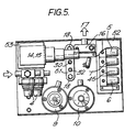
- FIG. 5 it is illustrated how the various components of the system may be arranged so as to form a compact unit.
- the various components are secured to a common mounting plate or tray 50, on the underside of which are located the combined mixer and surge dampers 8,11 and the booster pump 46 and relief valve 47 for the gas flow to the vapourisers.
- the other components are mounted to the top of the tray 50 which includes an aperture 51 providing access to the inlet and outlet ducts formed in the connecting plate 20 of the mixer and surge damper unit.
- the aperture also provides access to the outlet jets 13 of the pulsed valves.
- the solenoid valves 5,6,7,45 are enclosed in a common housing 52 which includes sound insulation; the back pressure valves 9,10 are mounted side by side opposite the second mixing chamber 16, and the inlet regulating valves 4 are secured to a common mounting next to the vapouriser selector valves 14,15.
- a printed circuit board 53 for the control circuitry may conveniently be located beneath the vapourised selector valves 14,15.
Abstract
Description
- This invention relates to apparatus for the mixing and smoothing of gas flows and is particularly concerned with apparatus adapted to produce a smooth and regulated flow of two or more mixed gases for use in the medical field of anaesthesia apparatus.
- In conventional anaesthesia apparatus a patient is supplied with a mixture of at least two gases, for example, oxygen and air or nitrous oxide, the mixed gases being dosed with vapourised anaesthetic drugs. With such apparatus it is essential that the proportions of the various gases in the mixture supplied to the patient are precisely regulated and furthermore a particularly smooth overall flow is required. It has been proposed to control the relative proportions of the constituent gases by means of a pulsed control valve in the supply line of each gas, the frequency or period of the valve pulses regulating the flow rate of the gas. Such an arrangement is advantageous in that the proportions of the gases may be set very accurately within a wide range of possible values. Furthermore, the pulsed valves, being solenoid controlled, are inherently suitable for use with electronic control circuitry. However, a major drawback with such an arrangement is that the resulting flow of the mixed gases is heavily pulsed both in terms of its instantaneous flow rate and in terms of the instantaneous relative proportions of its constituents. Such fluctuations are clearly undesirable and can be harmful to the patient.
- Viewed from a first aspect the invention provides apparatus for mixing and smoothing the flow of two or more gases, comprising a mixing chamber with at least two inlet ducts and an outlet duct, the mixing chamber being adapted to absorb fluctuations in the pressure of the gases therein, and a valve connected downstream of the chamber adapted to maintain a substantially constant pressure at said chamber outlet duct.
- The series arrangement of a mixing chamber which acts as a surge damper and a substantially constant back pressure valve is such that any fluctuations in the flow of the inlet gases are attenuated and a substantially smooth flow of the mixed gases may be obtained from an outlet of the back pressure valve. Apparatus in accordance with the invention is therefore particularly suitable for mixing and smoothing regulated flows of different gases produced by pulsed control valves in an anaesthesia system.
- In a preferred embodiment, the mixing chamber is cylindrical in shape, and the inlet ducts are arranged such that the gases enter the chamber tangentially in opposite directions. In this way the inlet flows tend to produce toroidal currents within the chamber which are in opposed senses, and this increases the efficiency of the mixing of the gases therefore minimising instantaneous variations in the relative proportions of the constituent gases in the outlet flow.
- The mixing chamber is preferably adapted to absorb fluctuations in gas pressure through the provision of a spring loaded piston which defines one wall of the chamber and which is outwardly displaceable in response to increases in gas pressure within the chamber. Sealing means for the piston may take any convenient form, for example sliding O-rings disposed between the piston and the chamber wall. Alternatively the gas pressure may act on the piston through a flexible rolling diaphragm seal which is secured across the chamber adjacent to the piston and prevents gases escaping around the periphery of the piston.
- In a particularly advantageous embodiment, the constant back pressure valve is a variable orifice valve adapted to produce a substantially constant back pressure over a wide range of gas flow rates. Thus, a required operational gas pressure within the mixing chamber for efficient flow smoothing is maintained over a wide range of flow rates, and this is particularly important in an anaesthesia system where the required total flow of gases delivered to a patient might vary considerably. A preferred embodiment of back pressure valve includes a gravity loaded plunger or float slidably mounted in a vertically disposed tapered passage. In use the flow of mixed gases from the mixing chamber outlet is passed upwardly through the passage such that the plunger is forced upwardly until an equilibrium position is reached where the back pressure is equal to the weight of the plunger assembly. Preferably the plunger includes angled slots or channels around its periphery such that the passage of gas produces a rotational torque on the plunger. The resulting rotation of the plunger reduces the influence of friction and mechanical shock within the valve. A preferred embodiment of back pressure valve has been found to produce a substantially constant back pressure over flow rates varying between two and eighteen litres per minute.
- Where particularly efficient attenuation is required the apparatus may include a second surge damper and constant back pressure valve arranged in series downstream of the first constant back pressure valve. The second surge damper may be of similar construction to the mixing chamber and thus preferably comprises an enclosed cylindrical chamber one wall of which is defined by a spring loaded damping piston. In a preferred embodiment, the mixing chamber and second surge damper are secured together in back-to-back relationship with a central connecting plate disposed therebetween. In this embodiment, the gases may conveniently be transmitted to and from the chambers via conduits formed in the connecting plate. The back-to-back configuration of the two cylindrical chambers provides a particularly compact unit.
- Clearly the overall attenuation of a variable or pulsed flow is greatly increased through the use of two surge damper and back pressure valve combinations arranged in series. If for example the attenuation factor of each combination is 80%, then the first combination would transmit to the
second combination 20% of any pulse entering the apparatus; the second combination however would reduce this transmission to 20% of 20%, that is 4% of the original pulse at the inlet. - In many instances it may be desirable to measure the rate of gas flow through the apparatus, and therefore a preferred embodiment of the invention includes a metering device for measuring the flow. The preferred form of constant back pressure value discussed above may conveniently be adapted for flow measurement, since the vertical displacement of the float or plunger thereof is related to the flow rate. In a preferred embodiment, a ferromagnetic rod is secured to and extends upwardly of the plunger assembly and is movable therewith. Displacement is measured by means of an assembly of inductance coils which surround the rod, changes in inductance being indicative of vertical movements of the plunger. Where fluctuating flows occur through the valve, an integral value of inductance may be obtained such that the average flow rate over a certain period of time is measured. This reduces the possibility of errors arising due to, for example, the plunger sticking within the passage. The preferred form of flow meter is particularly suitable for use with electronic control circuitry adapted continuously to monitor the gas flow rate through the apparatus.
- Viewed from a second aspect the invention provides a method of mixing and smoothing the flow of two or more gases comprising introducing the gases into an enclosed mixing chamber, the mixing chamber being adapted to absorb fluctuations in the pressure of the gases therein, and passing the mixed gases through a valve located downstream of the mixing chamber adapted to maintain a subtantially constant pressure at the outlet of said chamber.
- As mentioned above, the apparatus and method in accordance with the first and second aspects of the invention are particularly suited for the supply of mixed gases to a patient in an anaesthesia system. Thus, viewed from a third aspect the invention provides gas supply apparatus for an anaesthesia system comprising two or more pulsed valves adapted to produce regulated flows of two or more gases, a mixing chamber downstream of the valves in which the gases are mixed, surge damper means and back pressure valve means for attenuating pulses in the mixed gas flow, means for directing a controlled proportion of the total gas flow to anaesthetic drug dosing means, and a second mixing chamber for remixing the dosed gases with the main gas flow.
- Preferably the outlet orifices or jets of the pulsed valves are mounted so as to be in good thermal communication with one another. This is important to minimise the effect of relative thermal expansion or contraction of the orifices which can render the relative flow rates of the two gases inaccurate. This problem is significant where only a small percentage of one gas is required and thus the cooling effect resulting from the gas flow through one valve is very much less than that occuring from the gas flow through the other valve. In the preferred configuration of back-to-back cylindrical surge dampers discussed above, the valve jets may conveniently be disposed in suitable orifices formed in the common connecting plate between the two cylinders.
- In a preferred form of the invention, the various components of the system are arranged on a common mounting plate or tray thus forming a compact unit. Through the use of the preferred inductance flow meter together with solenoid controlled pulsed valves, the system lends itself to electronic control and monitoring by a microprocessor.
- A preferred embodiment of the invention will now be described, by way of example only, with reference to the accompanying drawings, wherein:
- Figure 1 is a schematic diagram illustrating gas supply apparatus for an anaesthesia system;
- Figure 2 is a sectional view through a combined mixing chamber and surge damper?
- Figure 3 is a section taken along line III-III in Figure 2;
- Figure 4 is a sectional view illustrating a preferred physical layout of the apparatus of Figure 1, and
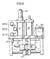
- Figure 6 is a side elevation of the apparatus shown in Figure 5.
- Referring firstly to Figure 1, gas supply apparatus for an anaesthesia system includes three
inlet ducts 1, 2, 3 which in use are connected respectively to pressurised supplies of oxygen, nitrous oxide and air at pressures in the order of 60 p.s.i. Theinlets 1,2,3 lead viapressure regulating valves 4 and solenoid controlledvalves surge damper 8, two constantback pressure valves back pressure valve 10, a controlled proportion of the gas flow is directed in a manner to be described via aline 12 to a selector valve 14 which in use is connected to a number of vapourisers (not shown) for dosing the mixed gases with appropriate anaesthetic drugs. Aselector valve 15 receives the dosed gases which are returned to the main flow via a line 3 and asecond mixing chamber 16. The anaesthetic gases for supply to a patient leave thechamber 16 via anoutlet duct 17. - In the illustrated embodiment, oxygen from the
inlet 1 is mixed with either air or nitrous oxide, although clearly additional inlets might be provided for alternative gases. The solenoid controlledvalve 5 selects whether nitrous oxide from the inlet 2 or air from the inlet 3 enters the system. The solenoid controlledvalves 6 and 7 are pulsed metering valves adapted to regulate precisely the flow rates of the gases to required mean values such that the quantity of each gas supplied to a patient is accurately controlled. The gas pressure upstream of thevalves 6, 7 is held constant by the regulatingvalves 4, and the flow rates through themetering valves 6,7 is therefore dependent upon the duration of the open periods of thevalves 6,7. In a preferred arrangement, control circuitry (not shown) for the apparatus includes means for generating a high frequency fundamental signal and the open pulses of each valve consist of an integral multiple of the period of this signal. In this way the length of the open periods of thevalves 6,7 and thus the flow rates may be incrementally varied with a high degree of accuracy. - The
metering valves 6,7 produce pulsed gas flows which are introduced into the combined mixing chamber andsurge damper 8 via respective valve nozzles orjets 18 having small orifices which may be adjustable to compensate for differences in density and viscosity of the gases such that the same volume of each gas is passed for a given open period of eithervalve 6,7. Alternatively the size of the jet orifices may be fixed and gas density and viscosity differences may be compensated for by adjusting thepressure regulating valves 4. As described below, thejets 18 are mounted within a common metal plate and are therefore in mutual thermal contact. Thus relative temperature variations of the jets due to different gas flow rates therethrough are minimised. - Referring now to Figures 2 and 3, the details of the combined mixing chamber and
surge damper 8 are illustrated. The chamber includes acylindrical housing 19 closed at one end by a connectingplate 20 and at the other end by an end plate 21 including anaperture 22 open to the atmosphere. The end plate 21 mounts apiston 23 which is movable against the action of twocoil springs piston 23 defines a side wall of anenclosed mixing chamber 26. A perfect seal is ensured by aflexible rolling diaphragm 27 which is secured across the interior of thecylinder 19 and overlies the piston. Formed in the connectingplate 20 are twoinlet orifices chamber 26, and a centrally disposed outlet orifice. The jets of thepulsed metering valves 6,7 may conveniently be disposed inenlarged end portions 31 of the inlet orifices 28,29 thereby ensuring mutual thermal contact therebetween. It will be seen that theorifices chamber 26 will tend to produce circulating currents in opposite directions; this promotes efficient mixing of the two gases and thus reduces the possibility of instantaneous variations in the relative concentrations of the constituent gases. - The
outlet 30 is connected to thevalve 9 which is adapted to maintain a substantially constant back pressure over a wide range of flow rates in a manner to be described. The spring loadedpiston 23 acts as a surge damper which absorbs increases in gas pressure within thechamber 26 owing to the pulsed inlet flow and thus the series combination of chamber and back pressure valve constitutes a mechanical resistance and compliance effective to attenuate the pulses and smooth the gas flow. Such a combination may provide an attenuation factor in the order of 80%. For further attenuation, as shown in Figure 1 asecond surge damper 11 and backpressure valve 20 are located downstream of the first. Thesurge damper 11 is of similar construction to the combined mixing chamber andsurge damper 8, and is mounted in back-to-back relationship therewith to the connectingplate 20. Thesurge damper 11 includes a damping piston and rolling diaphragm which although not shown in Figure 2 are similar to thepiston 23 anddiaphragm 27 of the combined mixing chamber andsurge damper 8. Thesurge damper 11 includes only asingle inlet 31 and anoutlet 32 which are again formed as bores in the common connectingplate 20. It should be noted that the gas pressure in the combined mixer andsurge damper 8 will be twice that in thesurge damper 11, since the effects of thevalves surge damper 11 to the operating pressure, the piston thereof is biased by only a single coil spring of similar rate tosprings - Referring now to Figure 4, details of the constant
back pressure valve 9 are illustrated. Thevalve 9 includes aninlet 33 and anoutlet 34 connected by a vertical taperedpassage 35 defined by ahousing 36. Slidably mounted in thepassage 35 is aplunger 37 secured to ashaft 37. Theshaft 37 mounts at its lower end aweight 38 which is disposed in aclosed chamber 39 in ahousing 37 below thepassage 35. Abush 40 locates the upper portion of theshaft 38, the bush being provided withgas flow apertures 41. Gas flowing though thepassage 35 urges theplunger 37 upwardly until the difference in pressure between the gas below and above the plunger is equal to the pressure resulting from the weight of the plunger and weight assembly. Such a valve has been found to maintain a substantially constant back pressure for gas flows in the range of 2 to 18 litres per minute. The restricted air gap between the outer periphery of theweight 38 and the inner wall of thechamber 39 provides damping for the plunger and prevents unwanted dynamic oscillations of the plunger which can occur with a pulsed gas flow. - The
valve 9 further comprises a flow metering device located in ahousing 42 secured to the top of thehousing 36. Theplunger shaft 38 mounts aferromagnetic stem 43 which extends upwardly through an assembly ofcoils 44. Measurements of the inductance between the coils are indicative of the vertical displacement of the plunger and therefore the gas flow rate through thevalve 9. Measurements are made by applying current to a central one of thecoils 44 and measuring the current induced in the other coils. The metering device is included in the upstream rather than the downstream back pressure valve since the flow upstream of thesecond surge damper 11 is still fluctuating to a degree. This enables an integral measurement to be made of the average flow over a short period of time which minimises the possibility of errors due to for example sticking of the plunger at low flow rates. - As mentioned above, a portion of the smoothed flow of mixed gases from the second
back pressure valve 10 is bypassed to an anaesthetic drug vapourising arrangement. The flow rate to thevapouriser selector valves 14,15 is regulated by a furtherpulsed metering valve 45. The required inlet operating pressure for thevalve 45 is maintained by the combination of abooster pump 46 and arelief valve 47. In an alternative arrangement, thebypass line 12 may be connected to the main flow line before the secondback pressure valve 10. In this way the pressure in theline 12 is increased and this may be necessary for low flow rates. - Referring finally to Figures 5 and 6, it is illustrated how the various components of the system may be arranged so as to form a compact unit. For reasons of clarity the connecting lines between the individual components have been omitted. The various components are secured to a common mounting plate or
tray 50, on the underside of which are located the combined mixer andsurge dampers booster pump 46 andrelief valve 47 for the gas flow to the vapourisers. The other components are mounted to the top of thetray 50 which includes anaperture 51 providing access to the inlet and outlet ducts formed in the connectingplate 20 of the mixer and surge damper unit. Thus the aperture also provides access to the outlet jets 13 of the pulsed valves. Thesolenoid valves common housing 52 which includes sound insulation; theback pressure valves second mixing chamber 16, and theinlet regulating valves 4 are secured to a common mounting next to thevapouriser selector valves 14,15. As mentioned above the system lends itself to automatic electronic control, and a printedcircuit board 53 for the control circuitry may conveniently be located beneath the vapourisedselector valves 14,15.
Claims (18)
Applications Claiming Priority (2)
| Application Number | Priority Date | Filing Date | Title |
|---|---|---|---|
| GB8305117 | 1983-02-24 | ||
| GB8305117A GB8305117D0 (en) | 1983-02-24 | 1983-02-24 | Gas mixing and flow smoothing apparatus |
Publications (2)
| Publication Number | Publication Date |
|---|---|
| EP0117699A2 true EP0117699A2 (en) | 1984-09-05 |
| EP0117699A3 EP0117699A3 (en) | 1987-04-01 |
Family
ID=10538519
Family Applications (1)
| Application Number | Title | Priority Date | Filing Date |
|---|---|---|---|
| EP19840301083 Withdrawn EP0117699A3 (en) | 1983-02-24 | 1984-02-20 | Gas mixing & flow smoothing apparatus |
Country Status (4)
| Country | Link |
|---|---|
| US (1) | US4576159A (en) |
| EP (1) | EP0117699A3 (en) |
| JP (1) | JPS59189927A (en) |
| GB (1) | GB8305117D0 (en) |
Cited By (8)
| Publication number | Priority date | Publication date | Assignee | Title |
|---|---|---|---|---|
| EP0361134A2 (en) * | 1988-09-27 | 1990-04-04 | Drägerwerk Aktiengesellschaft | Combined exchangeable fresh gas delivery unit for anaesthesia apparatus |
| EP0482261A1 (en) * | 1990-10-26 | 1992-04-29 | Puritan-Bennett Corporation | Ventilator control system |
| US5299568A (en) * | 1989-06-22 | 1994-04-05 | Puritan-Bennett Corporation | Method for controlling mixing and delivery of respiratory gas |
| US5323772A (en) * | 1991-06-28 | 1994-06-28 | Siemens Aktiengesellschaft | Respirator having an inspiration gas flow controlled by the expiration gas flow |
| US5335652A (en) * | 1991-04-06 | 1994-08-09 | Dragerwerk Aktiengesellschaft | Gas ratio control device for anesthetic apparatus |
| WO2007004898A1 (en) * | 2005-07-01 | 2007-01-11 | Fisher & Paykel Healthcare Limited | A breathing assistance apparatus with a manifold to add auxiliary gases to ambient gases |
| WO2017045624A1 (en) * | 2015-09-16 | 2017-03-23 | 12th Man Technologies, Inc. | Closed loop air-oxygen blender with high and low pressure air inlet |
| EP3705152B1 (en) | 2019-03-07 | 2022-10-26 | Löwenstein Medical Technology S.A. | Ventilator with mixer chamber and mixer chamber for a ventilator |
Families Citing this family (28)
| Publication number | Priority date | Publication date | Assignee | Title |
|---|---|---|---|---|
| DE3501095A1 (en) * | 1985-01-15 | 1986-07-17 | Gerd Prof. Dr. 8520 Erlangen Kobal | METHOD FOR MEASURING SENSORY QUALITIES AND DEVICE FOR IMPLEMENTING THE METHOD |
| DE3515072A1 (en) * | 1985-04-26 | 1986-11-06 | Gesellschaft für Strahlen- und Umweltforschung mbH, München, 8042 Neuherberg | PLANT FOR THE POLLUTANT GAS SUPPLY TO AN EXPOSURE CHAMBER |
| US4770168A (en) * | 1985-12-16 | 1988-09-13 | Tibor Rusz | Electrically controllable anesthesia vaporizer |
| US4932401A (en) * | 1988-04-01 | 1990-06-12 | Perkins Warren E | Two-gas variable ratio, variable dose, metering system and method of use |
| JP2715095B2 (en) * | 1988-04-11 | 1998-02-16 | 東芝機械株式会社 | Injection cylinder back pressure surge eliminator |
| DE3818280A1 (en) * | 1988-05-30 | 1989-12-07 | Draegerwerk Ag | DEVICE FOR ENRICHING BREATHING GAS WITH OXYGEN |
| US5127400A (en) * | 1990-03-23 | 1992-07-07 | Bird Products Corp. | Ventilator exhalation valve |
| US5159924A (en) * | 1990-10-03 | 1992-11-03 | Cegielski Michael J | Method and apparatus for selectively mixing gases |
| US5014694A (en) * | 1990-10-15 | 1991-05-14 | Bird Products Corporation | Ambient pressure air/oxygen blender |
| US5188455A (en) * | 1990-11-13 | 1993-02-23 | The Pennsylvania Research Corporation | Apparatus for remote mixing of fluids |
| US5664561A (en) * | 1991-04-26 | 1997-09-09 | The Boc Group Plc | High/low flow anesthetic vaporizer |
| FR2695831B1 (en) * | 1992-09-24 | 1994-11-10 | Air Liquide | Installation and method for supplying a gaseous mixture to the respiratory tract of a user. |
| FI100007B (en) * | 1994-05-06 | 1997-08-15 | Instrumentarium Oy | Arrangement with gas mixer |
| WO1996011717A1 (en) * | 1994-10-14 | 1996-04-25 | Bird Products Corporation | Portable drag compressor powered mechanical ventilator |
| JPH1130400A (en) * | 1997-07-09 | 1999-02-02 | Nippon Kuatsu Syst Kk | Pressure accumulating device |
| SE9704661D0 (en) * | 1997-12-15 | 1997-12-15 | Siemens Elema Ab | Fresh gas system and method of gasification of liquid anesthetic |
| WO2000059566A1 (en) * | 1999-04-07 | 2000-10-12 | Event Medical Limited | Breathing apparatus |
| US6135967A (en) | 1999-04-26 | 2000-10-24 | Fiorenza; Anthony Joseph | Respiratory ventilator with automatic flow calibration |
| US6240943B1 (en) | 1999-05-18 | 2001-06-05 | Loren C. Smith | Method and apparatus for maintaining a constant ratio of gases in a mixture subject to steady state and intermittent flow conditions |
| US6240919B1 (en) | 1999-06-07 | 2001-06-05 | Macdonald John J. | Method for providing respiratory airway support pressure |
| US7224285B2 (en) * | 2004-01-15 | 2007-05-29 | Honeywell Analytics, Ltd. | Gas monitor using electrochemical cell and method of operating |
| DE102006055779B3 (en) * | 2006-11-25 | 2008-03-13 | Dräger Medical AG & Co. KG | Gas mixing device for respirator, has control device designed to set operating pressure level in tank in operation type during gas dosing and to lower pressure level to another pressure level in another operation type |
| GB2446409B (en) * | 2007-02-06 | 2011-05-04 | Secretary Trade Ind Brit | Fluid mixtures |
| US20090241960A1 (en) * | 2008-04-01 | 2009-10-01 | Event Medical, Inc. | Dual high and low pressure breathing system |
| GB2474388B (en) | 2008-08-07 | 2012-11-21 | Agilent Technologies Inc | Synchronization of supply flow paths |
| US8267081B2 (en) * | 2009-02-20 | 2012-09-18 | Baxter International Inc. | Inhaled anesthetic agent therapy and delivery system |
| CN110267732A (en) * | 2015-12-11 | 2019-09-20 | 鞋匠技术公司 | Hypervariable advanced manufacturing technology |
| US20200282162A1 (en) * | 2019-03-08 | 2020-09-10 | Pioneer Astronautics | Systems, devices, and methods for improving ambient air quality during dental, medical, or veterinary procedures |
Citations (7)
| Publication number | Priority date | Publication date | Assignee | Title |
|---|---|---|---|---|
| US2778223A (en) * | 1953-11-02 | 1957-01-22 | Puritan Compressed Gas Corp | Flowmeter |
| FR1503289A (en) * | 1966-01-19 | 1967-11-24 | Aga Ab | Breathing apparatus for supplying gas in an adjustable proportion |
| US3412744A (en) * | 1965-09-17 | 1968-11-26 | Univ California | Mixed gas regulator |
| DE1933266A1 (en) * | 1969-07-01 | 1971-01-21 | Draegerwerk Ag | Process for mixing pressurized gases, particularly for respiratory and medical devices |
| US3586045A (en) * | 1969-10-07 | 1971-06-22 | Victor Equipment Co | Flow measuring device controlling both pressure and flow rate |
| US4015617A (en) * | 1975-03-25 | 1977-04-05 | Fraser Sweatman, Inc. | Analgesic apparatus |
| FR2333292A1 (en) * | 1975-11-27 | 1977-06-24 | Draegerwerk Ag | GAS MIXING DEVICE FOR RESPIRATORY, DIVING, MEDICAL AND LABORATORY PROTECTION TECHNIQUES |
Family Cites Families (4)
| Publication number | Priority date | Publication date | Assignee | Title |
|---|---|---|---|---|
| US2904076A (en) * | 1955-10-22 | 1959-09-15 | Engel | Pulsation dampener |
| US3487855A (en) * | 1967-10-16 | 1970-01-06 | Joseph Walter Lautenberger Jr | Pulsation dampener |
| US4026283A (en) * | 1973-12-28 | 1977-05-31 | Taylor Diving & Salvage Co., Inc. | Closed circuit, free-flow underwater breathing system |
| US4137912A (en) * | 1975-11-06 | 1979-02-06 | Diver's Exchange Inc. | Diving apparatus |
-
1983
- 1983-02-24 GB GB8305117A patent/GB8305117D0/en active Pending
-
1984
- 1984-02-20 EP EP19840301083 patent/EP0117699A3/en not_active Withdrawn
- 1984-02-23 US US06/582,912 patent/US4576159A/en not_active Expired - Fee Related
- 1984-02-24 JP JP59035105A patent/JPS59189927A/en active Pending
Patent Citations (7)
| Publication number | Priority date | Publication date | Assignee | Title |
|---|---|---|---|---|
| US2778223A (en) * | 1953-11-02 | 1957-01-22 | Puritan Compressed Gas Corp | Flowmeter |
| US3412744A (en) * | 1965-09-17 | 1968-11-26 | Univ California | Mixed gas regulator |
| FR1503289A (en) * | 1966-01-19 | 1967-11-24 | Aga Ab | Breathing apparatus for supplying gas in an adjustable proportion |
| DE1933266A1 (en) * | 1969-07-01 | 1971-01-21 | Draegerwerk Ag | Process for mixing pressurized gases, particularly for respiratory and medical devices |
| US3586045A (en) * | 1969-10-07 | 1971-06-22 | Victor Equipment Co | Flow measuring device controlling both pressure and flow rate |
| US4015617A (en) * | 1975-03-25 | 1977-04-05 | Fraser Sweatman, Inc. | Analgesic apparatus |
| FR2333292A1 (en) * | 1975-11-27 | 1977-06-24 | Draegerwerk Ag | GAS MIXING DEVICE FOR RESPIRATORY, DIVING, MEDICAL AND LABORATORY PROTECTION TECHNIQUES |
Cited By (17)
| Publication number | Priority date | Publication date | Assignee | Title |
|---|---|---|---|---|
| EP0361134A2 (en) * | 1988-09-27 | 1990-04-04 | Drägerwerk Aktiengesellschaft | Combined exchangeable fresh gas delivery unit for anaesthesia apparatus |
| EP0361134A3 (en) * | 1988-09-27 | 1990-10-10 | Drägerwerk Aktiengesellschaft | Combined exchangeable fresh gas delivery unit for anaesthesia apparatus |
| US5299568A (en) * | 1989-06-22 | 1994-04-05 | Puritan-Bennett Corporation | Method for controlling mixing and delivery of respiratory gas |
| US5383449A (en) * | 1989-06-22 | 1995-01-24 | Puritan-Bennett Corporation | Ventilator control system for mixing and delivery of gas |
| EP0482261A1 (en) * | 1990-10-26 | 1992-04-29 | Puritan-Bennett Corporation | Ventilator control system |
| US5335652A (en) * | 1991-04-06 | 1994-08-09 | Dragerwerk Aktiengesellschaft | Gas ratio control device for anesthetic apparatus |
| US5323772A (en) * | 1991-06-28 | 1994-06-28 | Siemens Aktiengesellschaft | Respirator having an inspiration gas flow controlled by the expiration gas flow |
| AU2006266564B2 (en) * | 2005-07-01 | 2012-03-22 | Fisher & Paykel Healthcare Limited | A breathing assistance apparatus with a manifold to add auxiliary gases to ambient gases |
| WO2007004898A1 (en) * | 2005-07-01 | 2007-01-11 | Fisher & Paykel Healthcare Limited | A breathing assistance apparatus with a manifold to add auxiliary gases to ambient gases |
| CN101212997B (en) * | 2005-07-01 | 2012-09-05 | 菲舍尔和佩克尔保健有限公司 | A breathing assistance apparatus |
| US8733353B2 (en) | 2005-07-01 | 2014-05-27 | Fisher & Paykel Healthcare Limited | Breathing assistance apparatus with a manifold to add auxiliary gases to ambient gases |
| US9656039B2 (en) | 2005-07-01 | 2017-05-23 | Fisher & Paykel Healthcare Limitied | Breathing assistance apparatus with a manifold to add auxiliary gases to ambient gases |
| US10722675B2 (en) | 2005-07-01 | 2020-07-28 | Fisher & Paykel Healthcare Limited | Breathing assistance apparatus with a manifold to add auxiliary gases to ambient gases |
| US11666726B2 (en) | 2005-07-01 | 2023-06-06 | Fisher & Paykel Healthcare Limited | Breathing assistance apparatus with a manifold to add auxiliary gases to ambient gases |
| WO2017045624A1 (en) * | 2015-09-16 | 2017-03-23 | 12th Man Technologies, Inc. | Closed loop air-oxygen blender with high and low pressure air inlet |
| CN108472469A (en) * | 2015-09-16 | 2018-08-31 | 第十二人科技公司 | With high and low-pressure air entrance closed loop air-oxygen mixer |
| EP3705152B1 (en) | 2019-03-07 | 2022-10-26 | Löwenstein Medical Technology S.A. | Ventilator with mixer chamber and mixer chamber for a ventilator |
Also Published As
| Publication number | Publication date |
|---|---|
| GB8305117D0 (en) | 1983-03-30 |
| US4576159A (en) | 1986-03-18 |
| EP0117699A3 (en) | 1987-04-01 |
| JPS59189927A (en) | 1984-10-27 |
Similar Documents
| Publication | Publication Date | Title |
|---|---|---|
| US4576159A (en) | Gas mixing and flow smoothing apparatus | |
| US5265594A (en) | Apparatus for regulating the flow-through amount of a flowing medium | |
| US5197462A (en) | Anesthetic metering device | |
| US4681530A (en) | Gas control device for controlling the fuel gas and oxidizing agent supply to a burner in an atomic absorption spectrometer | |
| US3633416A (en) | Method and apparatus for controlling and metering gas flow | |
| KR950701713A (en) | Method and apparatus for regulating a compressor lubrication system | |
| US3083721A (en) | Constant mass flow regulator | |
| US3534753A (en) | Ratio controller for gases | |
| KR940003838A (en) | Apparatus and methods for the preparation and maintenance of fluid mixtures in predetermined proportions | |
| US2676603A (en) | Fluid flow divider | |
| US3703172A (en) | Heated vaporizer anesthesia machine | |
| MXPA01000430A (en) | Gas mixing apparatus. | |
| US1290513A (en) | Proportioning-regulator for fluids. | |
| SE503291C2 (en) | Gas preparation system for an anesthetic device | |
| US3665959A (en) | Pressure regulating and reducing gas-flow meter for industrial installations | |
| DE2209779C3 (en) | Hot gas piston engine in which the fuel supply to the burner device is regulated by means of a control device that reacts to at least one parameter of the engine | |
| US4122707A (en) | Flow test stand | |
| DE1523270A1 (en) | Arrangement for measuring the speed and direction of a gas flow with optical and acoustic display of the measurement result, in particular for determining the vertical speed of an aircraft | |
| JPS5836976B2 (en) | anesthetic vaporizer | |
| US5860407A (en) | Gaseous fuel control system for engines | |
| GB1537239A (en) | Apparatus for flow-ratio control of gaseous fluids | |
| US4254789A (en) | Apparatus for mixing media, such as gases or liquids | |
| US4651730A (en) | Gas metering device for medical apparatus | |
| GB2206416B (en) | Calibration of fluid delivery equipment | |
| JPH07185004A (en) | Anesthetic vaporizer |
Legal Events
| Date | Code | Title | Description |
|---|---|---|---|
| PUAI | Public reference made under article 153(3) epc to a published international application that has entered the european phase |
Free format text: ORIGINAL CODE: 0009012 |
|
| AK | Designated contracting states |
Designated state(s): DE FR GB IT SE |
|
| PUAL | Search report despatched |
Free format text: ORIGINAL CODE: 0009013 |
|
| AK | Designated contracting states |
Kind code of ref document: A3 Designated state(s): DE FR GB IT SE |
|
| 17P | Request for examination filed |
Effective date: 19870611 |
|
| 17Q | First examination report despatched |
Effective date: 19881108 |
|
| STAA | Information on the status of an ep patent application or granted ep patent |
Free format text: STATUS: THE APPLICATION IS DEEMED TO BE WITHDRAWN |
|
| 18D | Application deemed to be withdrawn |
Effective date: 19890321 |
|
| RIN1 | Information on inventor provided before grant (corrected) |
Inventor name: SUGG, BASIL RAYMOND Inventor name: PALAYIWA, EILEEN Inventor name: TYRELL, PAUL JOHN Inventor name: LINDSAY-SCOTT, DAVID JOHN Inventor name: HAHN, CLIVE EDWARD WINSTON |