EP0118126A2 - Magnetic attraction system grinding method - Google Patents
Magnetic attraction system grinding method Download PDFInfo
- Publication number
- EP0118126A2 EP0118126A2 EP84102305A EP84102305A EP0118126A2 EP 0118126 A2 EP0118126 A2 EP 0118126A2 EP 84102305 A EP84102305 A EP 84102305A EP 84102305 A EP84102305 A EP 84102305A EP 0118126 A2 EP0118126 A2 EP 0118126A2
- Authority
- EP
- European Patent Office
- Prior art keywords
- grinding
- grindstone
- workpiece
- magnetic attraction
- magnetic
- Prior art date
- Legal status (The legal status is an assumption and is not a legal conclusion. Google has not performed a legal analysis and makes no representation as to the accuracy of the status listed.)
- Granted
Links
Images


Classifications
-
- B—PERFORMING OPERATIONS; TRANSPORTING
- B24—GRINDING; POLISHING
- B24B—MACHINES, DEVICES, OR PROCESSES FOR GRINDING OR POLISHING; DRESSING OR CONDITIONING OF ABRADING SURFACES; FEEDING OF GRINDING, POLISHING, OR LAPPING AGENTS
- B24B1/00—Processes of grinding or polishing; Use of auxiliary equipment in connection with such processes
-
- B—PERFORMING OPERATIONS; TRANSPORTING
- B24—GRINDING; POLISHING
- B24B—MACHINES, DEVICES, OR PROCESSES FOR GRINDING OR POLISHING; DRESSING OR CONDITIONING OF ABRADING SURFACES; FEEDING OF GRINDING, POLISHING, OR LAPPING AGENTS
- B24B35/00—Machines or devices designed for superfinishing surfaces on work, i.e. by means of abrading blocks reciprocating with high frequency
-
- B—PERFORMING OPERATIONS; TRANSPORTING
- B24—GRINDING; POLISHING
- B24B—MACHINES, DEVICES, OR PROCESSES FOR GRINDING OR POLISHING; DRESSING OR CONDITIONING OF ABRADING SURFACES; FEEDING OF GRINDING, POLISHING, OR LAPPING AGENTS
- B24B49/00—Measuring or gauging equipment for controlling the feed movement of the grinding tool or work; Arrangements of indicating or measuring equipment, e.g. for indicating the start of the grinding operation
- B24B49/16—Measuring or gauging equipment for controlling the feed movement of the grinding tool or work; Arrangements of indicating or measuring equipment, e.g. for indicating the start of the grinding operation taking regard of the load
Definitions
- the present invention relates to a grinding method to grind a workpiece of ferrous and/or non-ferrous metals, alloys containing at least one or more materials of them and the others with the use of magnetic attraction system.
- a "dead-weight" system is one of the so-contrived grinding methods, in which a grindstone loaded with a certain weight is fitted to an end of the robot arm which is actuated to X - and Y-directions of the coordinates.
- the surface to be ground comprises a complicated pattern like this therein, the grinding motion will inevitably be affected by a gravity of the weight loa.ded. As the result, it becomes impossible to do a grinding of side surface and also a profiling of free curved surface. Especially, there will be such cases that a proper grind can not be attained because a grinding pressure is affected by an inclination of the surface to be ground and in consequence can not be loaded evenly on the workpiece surface.
- a primary object of the present invention to eliminate the defects of prior art as outlined above and to provide such an appropriate and improved grinding method for users that the inertia and reaction forces are scarcely produced and the frictional vibrations are hardly caused even under severe grinding conditions and that the grinding pressure is kept constantly and the grinding performance suits the profiling work of free curved surface or side surface and the grinding work of dies or the like as well as the same work by a robot.
- the present invention intends to make a change in a conception of prior art that the grinding pressure may be obtained by a pressurization from an external equipment and to provide a new method and an apparatus contrived to obtain the grinding pressure by an attractive force to magnetically attract the grindstone onto a surface of workpiece. That is to say, this method under the present invention is to perform the grinding work by a mechanism and its operation contrived to move the grindstone along the surface of workpiece to be ground by the aid of magnetic circuit formed between an abrasive tool and a workpiece.
- a numeric number "1" is a desired workpiece such as dies or the like to be ground
- "2" is a grindstone
- "3" is a magnetic circuit forming means.
- the grindstone elements 2 & 2 are installed at each end of said magnetic circuit forming means 3.
- the method and apparatus of the present invention are contrived to grind the surface 11 of workpiece with the abrasive particles containBd - in the grindstone 2 in such a way that initially when forming the magnetic circuit as shown by broken line between the grindstone and the workpiece 1 with the use of magnetic circuit forming means 3 and exciting it electrically the grinding pressure required to grind the workpiece is then produced by the attractive force to attract the grindstone 2 onto the surface 11 of the workpiece by the function of the thus arranged magnetic circuit and under such a situation the grindstone 2 as well as the magnetic circuit forming means 3 are both moved along the surface 11 of workpiece.
- an electromagnetic system is employed as the said magnetic circuit forming means.
- the grindstone elements 2 & 2 are installed at the bottoms of core elements 4 & 4 and the coil elements 5 & 5 are wound up around said core elements 4 & 4 which are combined by a connector means 6.
- the magnetic circuit is thus integrated by such arrangement of core elements 4 & 4, connector means 6, grindstone elements 2 & 2 and workpiece 1.
- a lower connector means 7 made of non-magnetic material, e.g., aluminum alloy, etc. is arranged opposite to the aforementioned connector means 6.
- This lower connector means 7 is coupled with the said connector means 6 by using a binding member 8 and the thus coupled member serves as a holder of magnet assembly.
- a sleeve 9 made of brass or other metals having a minor friction coefficient is fitted between said connector means 6 and lower connector means 7.
- a coil 5 is wound up around an outer circumference of this sleeve 9, while the aforementioned core 4 is arranged to freely move to the axial directions through the inside of this sleeve.
- the grindstone 2 is attached pivotably to the bottoms of the core elements 4 & 4 respectively.
- the aforementioned holder is connected to an arm 12 through a joint section 10.
- a screw shaft 14 is screw- connected to a slide 13 located at the rear side of this arm 12 and also an end of the screw shaft is connected to a reversible motor 15.
- the reversible motor 15 provides a reciprocating movement for the slide 13 through a normal and reverse revolutions of the screw shaft 14 and a sliding movement for the grindstone 2 along the surface 11 of workpiece through the arm 12 and the holder 8. During these operations, when powering to the coil, the grindstone 2 will be attracted directly to the surface 11 of workpiece, thus the grinding pressure can be produced.
- a mechanism to move the arm and the holder may be set up by an optional construction.
- FIG.4 an embodiment whose slidingmovement of the grindstone 2 along the surface 11 of the workpiece is performed by a rotary movement instead of the rectilinearly reciprocating movement is illustrated therein.
- the coil elements 5 & 5 are wound up around the outer circumference of the lower member (lower holder) 7, and the core elements 4 & 4 are inserted through each member of the upper holder 6, coil 5 and lower holder 7.
- a revolving shaft 17 having a brush 18 is inserted through the upper holder 6.
- Figs.5 and 6 an embodiment employed a permanent magnet system as the magnetic circuit forming means is illustrated therein and Fig.5 shows an aspect to recti- linearlly reciprocate the grindstone along the surface, and Fig.6 shows an aspect arranged to bring the grindstone to rotary movement.
- the grindstone 2 is arranged fixedly or movably under the permanent magnet 4' which is attached movably to the axial directions to the holder 8.
- the permanent magnet 4' which is attached movably to the axial directions to the holder 8.
- the grindstone 2 has a shape coagulated the particles of grindstone with a bonding agent.
- a bonding agent In the case of a thin-shaped grindstone, it may be allowable to use a non-magnetic material as the bonding agent.
- a magnetic material As its typical example, a cast iron metallic powders bonded grindstone as shown in Figs. 7 and 7(a) has been known.
- This cast iron metallic powders bonded grindstone is manufactured in such a process that the cast iron powders having a fixed particle size are initially mixed with the grindstone particles and/or further carbonyl iron powders in addition to the same and its mixture is then press-formed and finally sintered under a reducing atmosphere. And at the time of sintering, the grindstone particles 21 are retained on the cast iron base 20 as shown macroscopically in Fig. 7 (a).
- the said retaining force will be strengthened further because the minutest vacant spaces between the cast iron powders and the grindstone particles are filled up with the particles of a newly formed cast iron matter 20' which is produced by chemical reaction of the added carbonyl iron powders and the carbon powders contained in the cast iron powders.
- a base metal 23 made of the cast iron matter is mono-block formed together with the grindstone member 22 and a through-hole 24 for a pivot pin is bored in this base metal 23.
- the grindstone and the permanent magnet are combined in one as in Figs.4 and 6, it is desirable to form the grindstone 22 containing the grindstone particles only at the bottom portion.
- the coil 5, core 4 and permanent magnet 4' are respectively composed of plural sets from the reason that the magnetic circuit must be formed between the grindstone 2 and the surface 1 of workpiece, however, when they have a plurality of S/N polarities as in Fig.8, it is warrantable to form them in a shape of mono-block construction. In this case, there is no objection even if the magnet is of a grindstone particles containing type.
- numeric number 25 shows a non-slip key and likewise 26 is a swivel arrester.
- the grinding operation according to the invention is carried out by initially forming a magnetic circuit between the grindstone 2 and the surface 1 of workpiece, thereby producing a magnetic attraction force therebetween without giving such external forces as a weight, spring force or fluid power'to the grindstone so as to produce a grinding pressure. For this reason, a reaction force to the arm and other members for moving the grindstone is scarcely produced and their inertia force also becomes smaller. Accordingly, a dynamic performance at the time when moving the grindstone at high speed is considerably improved, thus assuring an ease-of- control of the grindstone for the users.
- the grinding pressure is given by magnetic attraction force produced between the grindstone and the surface of workpiece and the external force is required merely for moving the "grindstone as a rigid body" horizontally, so that a spring force system is never formed between the grindstone and the workpiece and in consequence a frictional vibration is hard to be caused and also a lateral-striped pattern that might be created due to such frictional vibration can greatly be reduced.
- the core 4 and the permanent magnet 4' are arranged to be movable according to a displacement of workpiece surface to the normal line directions, a finish quality of the products can drastically be improved even in the case of grinding work of curved surface.
- the present invention provides an ideal method to arrest a creation of the aforementioned lateral-striped pattern by setting at random either one and/or more advantageously both of the moving stroke frequency (at the returning point) of grinding tool including grindstone or the moving speed.
- the grinding work is practically finished by abutting one grind segment after the other subsequent grind segment seamlessly, if the moving stroke is constant, it is feared that a boundary line or a clear distinction is created between one grind segment and another grind segment when abutting their ends each other. To avoid this drawback, it is advisable to set the moving stroke at random every segment. This control can easily be carried out through the instructions of computer or the like.
- the method of the present invention provides a grinding pressure by the magnetic attraction force to attract the grindstone onto the surface of workpiece, it is feasible to grind not only for plane surface but also for side surface or curved surface.
- a grinding point is apt to slip out of the position to a normal line direction due to a displacement of the workpiece surface, as seen in Fig.9 (a). This brings about a fluctuation in the grinding pressure and in consequence deteriorates a quality of profile grinding, thus resulting in a creation of inferior products.
- the method of the present invention there are no fluctuations of grinding point and grinding pressure because the attractive force "P" which is in diametrically opposite relation to the normal line force, as in Fig.9(b), influences on the grindstone 2, and in consequence a superior profile grinding can be attained.
- This can be made more efficient by arranging the core and/or the permanent magnet, which have a unitized or combined relation with the grindstone 2, movably to the axial directions, or otherwise by arranging the grindstone 2 rotatably with the bottom end of the core or the permanent magnet as a center.
- the method of the present invention can be applied even for the grinding work of complicatedly curved surface.
- the method of the present invention has further such an outstanding advantage that the workpiece 1 is hard to be magnetized because the reciprocating or rotating movement is given only to the grindstone 2 but not given to the workpiece though the magnetic circuit is formed between the grindstone 2 and the workpiece 1.
- the magnetic force values measured before and after the grinding works are both 1 or 5 G. This means that there is no difference in magnetic force before and after the grinding works. Accordingly, it is advisable to use an AC current for generation of the magnetic force or to grind the workpiece further at a working space of N-polarity following after completing the grind at a working space of S-polarity.
- the grinding pressure can easily be controlled by detecting a variation of current value supplied to the coil 5.
- This system has further an excellent advantage that a disposition of the chips can easily be carried out. That is to say, when a large quantity of chips are produced and adsorbed to the magnet assembly, such adsorption of the chips brings about a power interruption, i.e. a demagnetization of the magnet, which causes the grinding area to release and makes it easy to eliminate the chips out of the grinding area.
- the permanent magnet system is adopted which also belongs to a claim of the present invention, the grinding pressure is impossible to be changed during the operation but an overall construction of the magnetic circuit can be integrated simply and lightly in weight.
- the method and apparatus according to the present invention can be applied for various factory works such as a scalar type or a rectangular coordinates type robot works as well as an internal grinding or other general grinding works, and make it possible to use a magnetic file, magnetic grindstone, magnetic sand paper and so on for such grinding works.
- the magnetic attraction system grinding method and its apparatus can provide such various advantages for users that the inertia force and reaction force as well as the frictional vibration are scarcely produced and that the grinding pressure can always be maintained at a constant level which suits the state of side surface or free curved surface regardless how the inclination of profiling surface is.
- the method and apparatus of the present invention enable making a grinding machine lighter in weight and smaller in size than any of conventional machines and also applying to all the abrasive works for dies and others with the use of robot, thus assuring the best efficiency in grinding work for users.
Abstract
Description
- The present invention relates to a grinding method to grind a workpiece of ferrous and/or non-ferrous metals, alloys containing at least one or more materials of them and the others with the use of magnetic attraction system.
- Although a machining process has rapidly been automated and a machining accuracy has also been greatly improved as a popularization of NC machine tools or the like goes on, a grinding or polishing work are still taking an important role in final finishing processes, which are at present almost carried out by manual methods requiring much time and labor.
- Analyzing these manual finishing-works from a viewpoint of performance, most of their works are characterized by a monotonous pattern to repeat a rectilinear motion while pressing a grindstone on a surface to be ground and in general the rectilinear motion itself is relatively simple. Accordingly if the user attaches a grinding tool to an end of a robot arm and teaches such rectilinear motion to the robot and re-enacts it, an automatization of the grinding process will soon be possible to be realized. For instance, a "dead-weight" system is one of the so-contrived grinding methods, in which a grindstone loaded with a certain weight is fitted to an end of the robot arm which is actuated to X - and Y-directions of the coordinates.
- In this "dead-weight" system, however, the whole weight or-the grinding tool itself becomes considerably heavier and also a moment of inertia affected on the arm becomes too large because a grinding pressure is produced by a loaded weight. Consequently it is impossible to move the grindstone speedy and stably on the surface to be ground and in the worst case there may be some happenings that the grindstone leaps up or rebounds from the surface to be ground. This inevitably results in a deterioration of the grinding performance. Besides, since a spring force system will be most likely formed in a pressing means of the grindstone as a result of the employment of a weight, the frictional vibration at the time of grinding work becomes larger because it is superposed upon a natural vibration of the arm. In addition to the above, there may be some cases where several laterally-striped patterns are created perpendicularly against a grinding direction along the surface to be ground and in consequence an optional grind surface is hard to be obtained.
- Also, in actual cases there are many varieties in the shape of workpiece surface, e.g., as typified in dies or the like, in which not only a simple straight-surface but also a complex curved-surface or a combined pattern thereof are included, besides their patterns are often formed not merely on a plane surface but on a side or cavity surface.
- If the surface to be ground comprises a complicated pattern like this therein, the grinding motion will inevitably be affected by a gravity of the weight loa.ded. As the result, it becomes impossible to do a grinding of side surface and also a profiling of free curved surface. Especially, there will be such cases that a proper grind can not be attained because a grinding pressure is affected by an inclination of the surface to be ground and in consequence can not be loaded evenly on the workpiece surface.
- It is, therefore, a primary object of the present invention to eliminate the defects of prior art as outlined above and to provide such an appropriate and improved grinding method for users that the inertia and reaction forces are scarcely produced and the frictional vibrations are hardly caused even under severe grinding conditions and that the grinding pressure is kept constantly and the grinding performance suits the profiling work of free curved surface or side surface and the grinding work of dies or the like as well as the same work by a robot.
- It is another object of the present invention to provide a new and efficient grinding tool and automatic grinding apparatus which the aforementioned various features of design and grinding method are embodied therein.
- In order to attain these objects, the present invention intends to make a change in a conception of prior art that the grinding pressure may be obtained by a pressurization from an external equipment and to provide a new method and an apparatus contrived to obtain the grinding pressure by an attractive force to magnetically attract the grindstone onto a surface of workpiece. That is to say, this method under the present invention is to perform the grinding work by a mechanism and its operation contrived to move the grindstone along the surface of workpiece to be ground by the aid of magnetic circuit formed between an abrasive tool and a workpiece.
- The present invention, both as to its mechanism and grinding method, together with further advantages thereof, will more fully-be understood by reference to the following specification taken in connection with the accompanying drawings, in which ;
- Fig.1 is an illustration showing a fundamental principle of magnetic attraction system grinding method under the present invention.
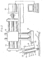
- Fig.2 is a partially sectioned side elevation view showing an example of grinding tool and grinding apparatus embodied the features of the present invention.
- Fig.3 is a partially sectioned front elevation view showing a principal part in Fig.2.
- Fig.4 is a perspective view showing an example of magnetic circuit adopted a rotary movement system.
- Fig.5 is a sectional elevation view of a principal part showing an example composed the magnetic circuit with a permanent magnet.
- Fig.6 is a perspective view showing an embodiment of the permanent magnet and the rotary movement system.
- Fig.7 is a longitudinally sectioned side elevation view showing an example of grindstone employed in the present invention.
- Fig.7(a) is a partially enlarged view of the grindstone.
- Fig.8 is a perspective view showing another example of the grindstone employed in the present invention.
- Figs.9(a) and 9(b) show a curved surface profiling work and, more particularly Fig.(a) shows a conventional dead-weight system's or spring system's grinding work and Fig.(b) shows a magnetic attraction system's grinding work of the present invention.
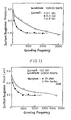
- Fig. 10 is a graph showing a relationship between a supply current and an attractive force of the grindstone in grinding method of the present invention.
- Fig.11 is a graph showing a relationship between a particle size of grindstone and a grinding performance.
- Fig.12 is a graph showing a relationship between a supply current and the grinding performance.
- Fig.13 is a graph showing a relationship between a change of material quality and the grinding performance.
- The present invention will now be described in further detail as to the specific embodimentsin connection with the accompanying drawings.
- Referring initially to Fig.1, the magnetic attraction system grinding method is in principle shown therein. A numeric number "1" is a desired workpiece such as dies or the like to be ground, "2" is a grindstone and "3" is a magnetic circuit forming means. The
grindstone elements 2 & 2 are installed at each end of said magnetic circuit forming means 3. The method and apparatus of the present invention are contrived to grind thesurface 11 of workpiece with the abrasive particles containBd-in thegrindstone 2 in such a way that initially when forming the magnetic circuit as shown by broken line between the grindstone and the workpiece 1 with the use of magneticcircuit forming means 3 and exciting it electrically the grinding pressure required to grind the workpiece is then produced by the attractive force to attract thegrindstone 2 onto thesurface 11 of the workpiece by the function of the thus arranged magnetic circuit and under such a situation thegrindstone 2 as well as the magnetic circuit forming means 3 are both moved along thesurface 11 of workpiece. - In this embodiment, an electromagnetic system is employed as the said magnetic circuit forming means. The
grindstone elements 2 & 2 are installed at the bottoms ofcore elements 4 & 4 and thecoil elements 5 & 5 are wound up around saidcore elements 4 & 4 which are combined by a connector means 6. The magnetic circuit is thus integrated by such arrangement ofcore elements 4 & 4, connector means 6,grindstone elements 2 & 2 and workpiece 1. - Referring now to Figs. 2 & 3, each example of grinding tool and automatic grinding apparatus which embody the features of the present invention is illustrated therein. A lower connector means 7 made of non-magnetic material, e.g., aluminum alloy, etc. is arranged opposite to the aforementioned connector means 6. This lower connector means 7 is coupled with the said connector means 6 by using a binding
member 8 and the thus coupled member serves as a holder of magnet assembly. Further asleeve 9 made of brass or other metals having a minor friction coefficient is fitted between said connector means 6 and lower connector means 7. Acoil 5 is wound up around an outer circumference of thissleeve 9, while theaforementioned core 4 is arranged to freely move to the axial directions through the inside of this sleeve. Thegrindstone 2 is attached pivotably to the bottoms of thecore elements 4 & 4 respectively. - And, the aforementioned holder is connected to an
arm 12 through ajoint section 10. Ascrew shaft 14 is screw- connected to aslide 13 located at the rear side of thisarm 12 and also an end of the screw shaft is connected to areversible motor 15. Thereversible motor 15 provides a reciprocating movement for theslide 13 through a normal and reverse revolutions of thescrew shaft 14 and a sliding movement for thegrindstone 2 along thesurface 11 of workpiece through thearm 12 and theholder 8. During these operations, when powering to the coil, thegrindstone 2 will be attracted directly to thesurface 11 of workpiece, thus the grinding pressure can be produced. - Incidentally, it goes without saying that a mechanism to move the arm and the holder may be set up by an optional construction.
- Referring next to Fig.4, an embodiment whose slidingmovement of the
grindstone 2 along thesurface 11 of the workpiece is performed by a rotary movement instead of the rectilinearly reciprocating movement is illustrated therein. In this embodiment, thecoil elements 5 & 5 are wound up around the outer circumference of the lower member (lower holder) 7, and thecore elements 4 & 4 are inserted through each member of theupper holder 6,coil 5 andlower holder 7. And, a revolvingshaft 17 having abrush 18 is inserted through theupper holder 6. - Referring then to Figs.5 and 6, an embodiment employed a permanent magnet system as the magnetic circuit forming means is illustrated therein and Fig.5 shows an aspect to recti- linearlly reciprocate the grindstone along the surface, and Fig.6 shows an aspect arranged to bring the grindstone to rotary movement. In either embodiment, the
grindstone 2 is arranged fixedly or movably under the permanent magnet 4' which is attached movably to the axial directions to theholder 8. For the other mechanisms, it suffices to say that they are shown with the same numeric numbers as those of the foregoing electromagnetic system. - In each drawing of Fig.1 through Fig.6, the
grindstone 2 has a shape coagulated the particles of grindstone with a bonding agent. In the case of a thin-shaped grindstone, it may be allowable to use a non-magnetic material as the bonding agent. However, in order to enhance the attractive force of the grindstone to thesurface 11 of workpiece, it is desirable to use a magnetic material as the bonding agent. As its typical example, a cast iron metallic powders bonded grindstone as shown in Figs. 7 and 7(a) has been known. 'This cast iron metallic powders bonded grindstone is manufactured in such a process that the cast iron powders having a fixed particle size are initially mixed with the grindstone particles and/or further carbonyl iron powders in addition to the same and its mixture is then press-formed and finally sintered under a reducing atmosphere. And at the time of sintering, thegrindstone particles 21 are retained on thecast iron base 20 as shown macroscopically in Fig. 7 (a). In relation to this, if the carbonyl iron powders are added into the cast iron powders, the said retaining force will be strengthened further because the minutest vacant spaces between the cast iron powders and the grindstone particles are filled up with the particles of a newly formed cast iron matter 20' which is produced by chemical reaction of the added carbonyl iron powders and the carbon powders contained in the cast iron powders. - When this cast iron powders bonded grindstone is employed instead of the conventional grindstone, many advantages will be obtained such that a clogging between the grindstone particles is hardly caused and the grindstone itself is hard to be worn away, besides a magnetic permeability is considerably high and in consequence provides more larger attractive force (grinding pressure) to the grindstone than that of conventional grindstone even when impressed the same current or the same magnetic force to said two grindstones because the cast iron is employed in base metal. Incidentally, it goes without saying that a grindstone - particle-containing-magnet can be used for this purpose which is made by mixing the grindstone particles with the magnet composing iron powders and sintering its mixture.
- This example is given in Figs. 4 and 6. In an embodiment shown in Fig.7, a
base metal 23 made of the cast iron matter is mono-block formed together with thegrindstone member 22 and a through-hole 24 for a pivot pin is bored in thisbase metal 23. Needless to say, it is possible to bond or stick thebase metal 23 to an end of thecore 4 or the permanent magnet 4'. In such a case that the grindstone and the permanent magnet are combined in one as in Figs.4 and 6, it is desirable to form thegrindstone 22 containing the grindstone particles only at the bottom portion. - Each example in Figs. 1 through 6, the
coil 5,core 4 and permanent magnet 4' are respectively composed of plural sets from the reason that the magnetic circuit must be formed between thegrindstone 2 and the surface 1 of workpiece, however, when they have a plurality of S/N polarities as in Fig.8, it is warrantable to form them in a shape of mono-block construction. In this case, there is no objection even if the magnet is of a grindstone particles containing type. - Although the present invention has been outlined as above with regard to a major part of its mechanism, for the other mechanical descriptions, it suffices to say that a
numeric number 25 shows a non-slip key and likewise 26 is a swivel arrester. - Next, the present invention will be explained mainly as to its function. The grinding operation according to the invention, as previously described, is carried out by initially forming a magnetic circuit between the
grindstone 2 and the surface 1 of workpiece, thereby producing a magnetic attraction force therebetween without giving such external forces as a weight, spring force or fluid power'to the grindstone so as to produce a grinding pressure. For this reason, a reaction force to the arm and other members for moving the grindstone is scarcely produced and their inertia force also becomes smaller. Accordingly, a dynamic performance at the time when moving the grindstone at high speed is considerably improved, thus assuring an ease-of- control of the grindstone for the users. - Besides, the grinding pressure is given by magnetic attraction force produced between the grindstone and the surface of workpiece and the external force is required merely for moving the "grindstone as a rigid body" horizontally, so that a spring force system is never formed between the grindstone and the workpiece and in consequence a frictional vibration is hard to be caused and also a lateral-striped pattern that might be created due to such frictional vibration can greatly be reduced. Especially, as the
core 4 and the permanent magnet 4' are arranged to be movable according to a displacement of workpiece surface to the normal line directions, a finish quality of the products can drastically be improved even in the case of grinding work of curved surface. - Further, the present invention provides an ideal method to arrest a creation of the aforementioned lateral-striped pattern by setting at random either one and/or more advantageously both of the moving stroke frequency (at the returning point) of grinding tool including grindstone or the moving speed. Although the grinding work is practically finished by abutting one grind segment after the other subsequent grind segment seamlessly, if the moving stroke is constant, it is feared that a boundary line or a clear distinction is created between one grind segment and another grind segment when abutting their ends each other. To avoid this drawback, it is advisable to set the moving stroke at random every segment. This control can easily be carried out through the instructions of computer or the like.
- Furthermore, as the method of the present invention provides a grinding pressure by the magnetic attraction force to attract the grindstone onto the surface of workpiece, it is feasible to grind not only for plane surface but also for side surface or curved surface. However, in the method of prior art such as a dead-weight system, spring force.system or the others which employ any external force for the grinding pressure, a grinding point is apt to slip out of the position to a normal line direction due to a displacement of the workpiece surface, as seen in Fig.9 (a). This brings about a fluctuation in the grinding pressure and in consequence deteriorates a quality of profile grinding, thus resulting in a creation of inferior products. On the contrary, in the method of the present invention, there are no fluctuations of grinding point and grinding pressure because the attractive force "P" which is in diametrically opposite relation to the normal line force, as in Fig.9(b), influences on the
grindstone 2, and in consequence a superior profile grinding can be attained. This can be made more efficient by arranging the core and/or the permanent magnet, which have a unitized or combined relation with thegrindstone 2, movably to the axial directions, or otherwise by arranging thegrindstone 2 rotatably with the bottom end of the core or the permanent magnet as a center. Thus, the method of the present invention can be applied even for the grinding work of complicatedly curved surface. - In addition to the above, the method of the present invention has further such an outstanding advantage that the workpiece 1 is hard to be magnetized because the reciprocating or rotating movement is given only to the
grindstone 2 but not given to the workpiece though the magnetic circuit is formed between thegrindstone 2 and the workpiece 1. - In one of the embodimentsthat the inventor et al have performei a grinding work for a workpiece of SK-material (150 x 80 x 3t ), the magnetic force values measured before and after the grinding works are both 1 or 5 G. This means that there is no difference in magnetic force before and after the grinding works. Accordingly, it is advisable to use an AC current for generation of the magnetic force or to grind the workpiece further at a working space of N-polarity following after completing the grind at a working space of S-polarity.
- Moreover, in the case where the magnetic circuit is composed of an electromagnet system which belongs to a claim of the present invention, the grinding pressure can easily be controlled by detecting a variation of current value supplied to the
coil 5. This system has further an excellent advantage that a disposition of the chips can easily be carried out. That is to say, when a large quantity of chips are produced and adsorbed to the magnet assembly, such adsorption of the chips brings about a power interruption, i.e. a demagnetization of the magnet, which causes the grinding area to release and makes it easy to eliminate the chips out of the grinding area. On the other hand, in the case where the permanent magnet system is adopted which also belongs to a claim of the present invention, the grinding pressure is impossible to be changed during the operation but an overall construction of the magnetic circuit can be integrated simply and lightly in weight. - The method and apparatus according to the present invention can be applied for various factory works such as a scalar type or a rectangular coordinates type robot works as well as an internal grinding or other general grinding works, and make it possible to use a magnetic file, magnetic grindstone, magnetic sand paper and so on for such grinding works.
- The present invention will finally be described in further detail on the basis of several exemplification tests in connection with the accompanying drawings.
- 1) A grinding experiment has been carried out with the use of a certain grinding machine as shown in Figs.2 and 3. This experiment has been practiced under the strictly controlled fundamental conditions, namely, the slide is reciprocated by a microcomputer-controlled DC motor; the magnetic attraction force of the grindstone is controlled by a DC powered solenoid coil; and the horizontal movement of grindstone is performed by X-Y coordinates table.
- 2) A cast iron powders bonded grindstone containing a diamond has been employed in this experiment. The size of grindstone was 15mm x 10 mm x 10 mm and an appropriate quantity of grindstone particles were retained only in the part of 1.5 mm deep of the superficial layer. The grindstone was made of a mixture of 7.5 wt % grindstone particles, 10 µm 0, 22.5wt % carbonyl iron powders and cast iron powders passed through No. 200 mesh sieve, and press-formed together with cast iron base powders, and then sintered under the temperature of 1140 °C.
Two workpieces of SK-material (Hvl8l) and pre-hardened steel (Hv489) were provided for this experiment. Also, an appropriate quantity of light-oil was used as an abrasive oil. The experiment has been applied to a side surface of a R75 mm cylinder at the speeds of 4.5 - 8 m/min. The electromagnet assembly was composed of the core elements having a distance between cores of 32 mm and the coil elements of 40 mm high, and set up at the inclination angle of 15 degrees from the joint section. - 3) Fig.10 shows a relationship between the current supplied to the coil and the magnetic attraction force to the grindstone (grinding pressure). As can be understood from Fig.10, a powerful grinding pressure is obtained because a cast iron powders bonded grindstone is employed in this experiment.
Referring next to Figs.11 through 13, each results of the experiments practiced under the aforementioned conditions is given therein. In these drawings, the grinding frequency in the axis of abscissa shows a frequency that the grindstone passes a returning point. Fig. 11 shows a difference of grinding performance made by the variation of grindstone particle size ; Fig.12 shows a difference of grinding performance made by the variation of supply current ; and Fig.13 shows a difference of grinding performance made by the variation of material quality respectively. The results show, throughout all of the experiments, that a curvature of the side surface can also be ground effectively which is difficult to perform by the dead-weight system and that lateral-striped patterns are scarcely created in said surface because the frictional vibrations in problem are also hardly caused by the grinding work. Thus a superior effect of this method has completely been exemplified. Incidentally, the reason why no difference could be found in performances between both tests of 0.5A and 0.9A is that the process efficiency already reached a saturation just at that grinding pressure. - 4) As has been understood, the lateral-striped patterns are scarcely created but, in order to eliminate them com- pletely, the exemplification tests have been carried out under the following three conditions instead of the fixed conditions (i.e. grinding speed: 8 m/min, stroke length: 50 mm) ;
- a) the grinding speed is constant and the stroke length is random (50 mm ± 10 mm)
- b) the grinding speed is 4.5 - 8 m/min and the stroke length is constant
- c) the grinding speed and the stroke length are both constant.
In these tests, the instruction of grinding speed and the positioning order of returning point are both given at random by the control from a microcomputer.
A remarkable effect of this method was recognized in all of the tests, especially the best result has been obtained under the conditions of c), where a boundary line between process segments could completely be eliminated because the stroke length was set at random. - As has been understood from the aforementioned detailed description, the magnetic attraction system grinding method and its apparatus according to the present invention can provide such various advantages for users that the inertia force and reaction force as well as the frictional vibration are scarcely produced and that the grinding pressure can always be maintained at a constant level which suits the state of side surface or free curved surface regardless how the inclination of profiling surface is. Besides, the method and apparatus of the present invention enable making a grinding machine lighter in weight and smaller in size than any of conventional machines and also applying to all the abrasive works for dies and others with the use of robot, thus assuring the best efficiency in grinding work for users.
Claims (9)
the magnetic circuit forming means is an electromagnet. "
the magnetic circuit forming means is a permanent magnet.
the abrasive tool is a magnetic material bonded grindstone.
said grindstone is driven by a rectilinearly reciprocating movement.
said grindstone is driven by a rotary movement.
said grindstone's operation is practiced by controlling at random at least either one of the grinding speed or the grinding stroke.
said magnetic circuit forming means is arranged movably according to the displacement of said grindstone to a normal line direction of the workpiece surface.
Priority Applications (1)
| Application Number | Priority Date | Filing Date | Title |
|---|---|---|---|
| AT84102305T ATE43274T1 (en) | 1983-03-04 | 1984-03-03 | GRINDING PROCESS WITH A MAGNETIC ATTRACTION SYSTEM. |
Applications Claiming Priority (2)
| Application Number | Priority Date | Filing Date | Title |
|---|---|---|---|
| JP58035612A JPS59161262A (en) | 1983-03-04 | 1983-03-04 | Magnetic attraction type method for abrasion |
| JP35612/83 | 1983-03-04 |
Publications (3)
| Publication Number | Publication Date |
|---|---|
| EP0118126A2 true EP0118126A2 (en) | 1984-09-12 |
| EP0118126A3 EP0118126A3 (en) | 1986-08-27 |
| EP0118126B1 EP0118126B1 (en) | 1989-05-24 |
Family
ID=12446662
Family Applications (1)
| Application Number | Title | Priority Date | Filing Date |
|---|---|---|---|
| EP84102305A Expired EP0118126B1 (en) | 1983-03-04 | 1984-03-03 | Magnetic attraction system grinding method |
Country Status (5)
| Country | Link |
|---|---|
| US (1) | US4603509A (en) |
| EP (1) | EP0118126B1 (en) |
| JP (1) | JPS59161262A (en) |
| AT (1) | ATE43274T1 (en) |
| DE (1) | DE3478289D1 (en) |
Cited By (6)
| Publication number | Priority date | Publication date | Assignee | Title |
|---|---|---|---|---|
| WO1985005060A1 (en) * | 1984-05-03 | 1985-11-21 | Fiziko-Tekhnichesky Institut Akademii Nauk Belorus | Magnetoabrasive machining device |
| EP0706856A1 (en) * | 1994-10-11 | 1996-04-17 | Ontrak Systems, Inc. | Polishing pad cluster for polishing a semiconductor wafer |
| US6083082A (en) * | 1999-08-30 | 2000-07-04 | Lam Research Corporation | Spindle assembly for force controlled polishing |
| US6336845B1 (en) | 1997-11-12 | 2002-01-08 | Lam Research Corporation | Method and apparatus for polishing semiconductor wafers |
| CN102225531A (en) * | 2011-05-21 | 2011-10-26 | 烟台鲁宝钢管有限责任公司 | Method for rapidly grinding carbon brush of direct current motor |
| CN106826539A (en) * | 2016-12-30 | 2017-06-13 | 赵善文 | Flexible abrasive material for surface grinding and the magnetically grinding component based on the abrasive material |
Families Citing this family (9)
| Publication number | Priority date | Publication date | Assignee | Title |
|---|---|---|---|---|
| DE3445001A1 (en) * | 1984-12-10 | 1986-06-19 | Hitachi Zosen Corp., Osaka | Process for mirror finishing a disc-shaped workpiece |
| JPH0622792B2 (en) * | 1985-04-09 | 1994-03-30 | キヤノン電子株式会社 | Deburring equipment |
| GB8811370D0 (en) * | 1988-05-13 | 1988-06-15 | Beckingham W J | Ski sharpener |
| JPH02120851U (en) * | 1989-03-15 | 1990-09-28 | ||
| US5283982A (en) * | 1992-04-01 | 1994-02-08 | Ltv Aerospace And Defense Company | Complex contour milling machine |
| US20070079841A1 (en) * | 2005-10-07 | 2007-04-12 | Flowery Beauty Products Inc. | Magnetic nail file and method of fabricating same |
| KR100783525B1 (en) | 2006-07-19 | 2007-12-11 | 건국대학교 산학협력단 | Effective deburring using permanent magnet abrasive finishing |
| CN111482890B (en) * | 2020-05-28 | 2021-05-25 | 浙江师范大学 | Magnetic grinding device and magnetic grinding control method |
| CN112706005B (en) * | 2020-12-31 | 2021-12-07 | 广州科源数控科技有限公司 | Pressure compensation device of grinding machine and using method thereof |
Citations (6)
| Publication number | Priority date | Publication date | Assignee | Title |
|---|---|---|---|---|
| US3093464A (en) * | 1959-01-16 | 1963-06-11 | Norton Co | Magnetic abrasive wheels, method of making them, and machine tools for using them |
| GB1108517A (en) * | 1965-11-30 | 1968-04-03 | Mullard Ltd | Improvements in and relating to methods of grinding |
| DE1502500A1 (en) * | 1965-09-03 | 1969-03-20 | Laepple August Gmbh & Co | Process for processing irregularly curved surfaces, e.g. on punches, dies, sheet metal holders or other molded parts of large tools, by grinding using a so-called grinding head or the like. and device for performing this process |
| DE2346431A1 (en) * | 1972-09-14 | 1974-03-21 | Buehler Ltd | METHOD AND DEVICE FOR GRINDING A SURFACE |
| CH599831A5 (en) * | 1977-02-15 | 1978-05-31 | Proizv Ob Turbostroenia | |
| SU1000246A1 (en) * | 1981-10-08 | 1983-02-28 | Физико-технический институт АН БССР | Abrasive working apparatus |
Family Cites Families (5)
| Publication number | Priority date | Publication date | Assignee | Title |
|---|---|---|---|---|
| US1833360A (en) * | 1929-12-06 | 1931-11-24 | Pittsburgh Plate Glass Co | Surfacing machine |
| US2056182A (en) * | 1934-02-08 | 1936-10-06 | Gardner Machine Co | Grinding machine |
| US2195049A (en) * | 1936-11-16 | 1940-03-26 | Chrysler Corp | Lapping apparatus |
| US4150511A (en) * | 1977-05-12 | 1979-04-24 | Proizvodstvennoe Obiedinenie Turbostroenia Leningradsky Metallichesky Zavod | Device for finishing shaped surfaces with an abrasive tool |
| JPS591160A (en) * | 1982-06-23 | 1984-01-06 | Toyo Kenmazai Kogyo Kk | Device for magnetically polishing flat surface of work |
-
1983
- 1983-03-04 JP JP58035612A patent/JPS59161262A/en active Granted
-
1984
- 1984-02-13 US US06/579,877 patent/US4603509A/en not_active Expired - Fee Related
- 1984-03-03 AT AT84102305T patent/ATE43274T1/en active
- 1984-03-03 EP EP84102305A patent/EP0118126B1/en not_active Expired
- 1984-03-03 DE DE8484102305T patent/DE3478289D1/en not_active Expired
Patent Citations (6)
| Publication number | Priority date | Publication date | Assignee | Title |
|---|---|---|---|---|
| US3093464A (en) * | 1959-01-16 | 1963-06-11 | Norton Co | Magnetic abrasive wheels, method of making them, and machine tools for using them |
| DE1502500A1 (en) * | 1965-09-03 | 1969-03-20 | Laepple August Gmbh & Co | Process for processing irregularly curved surfaces, e.g. on punches, dies, sheet metal holders or other molded parts of large tools, by grinding using a so-called grinding head or the like. and device for performing this process |
| GB1108517A (en) * | 1965-11-30 | 1968-04-03 | Mullard Ltd | Improvements in and relating to methods of grinding |
| DE2346431A1 (en) * | 1972-09-14 | 1974-03-21 | Buehler Ltd | METHOD AND DEVICE FOR GRINDING A SURFACE |
| CH599831A5 (en) * | 1977-02-15 | 1978-05-31 | Proizv Ob Turbostroenia | |
| SU1000246A1 (en) * | 1981-10-08 | 1983-02-28 | Физико-технический институт АН БССР | Abrasive working apparatus |
Cited By (13)
| Publication number | Priority date | Publication date | Assignee | Title |
|---|---|---|---|---|
| WO1985005060A1 (en) * | 1984-05-03 | 1985-11-21 | Fiziko-Tekhnichesky Institut Akademii Nauk Belorus | Magnetoabrasive machining device |
| FR2575956A1 (en) * | 1984-05-03 | 1986-07-18 | Fiz Tech I Akad Nauk | MAGNETO-ABRASIVE MACHINING DEVICE FOR EXTERIOR CYLINDRICAL SURFACES |
| GB2173433A (en) * | 1984-05-03 | 1986-10-15 | Fiz Tech I Akad Nauk | Magnetoabrasive machining device |
| EP0706856A1 (en) * | 1994-10-11 | 1996-04-17 | Ontrak Systems, Inc. | Polishing pad cluster for polishing a semiconductor wafer |
| US5575707A (en) * | 1994-10-11 | 1996-11-19 | Ontrak Systems, Inc. | Polishing pad cluster for polishing a semiconductor wafer |
| EP0919330A1 (en) * | 1994-10-11 | 1999-06-02 | Ontrak Systems, Inc. | Polishing pad cluster for polishing a semiconductor wafer |
| US6517418B2 (en) | 1997-11-12 | 2003-02-11 | Lam Research Corporation | Method of transporting a semiconductor wafer in a wafer polishing system |
| US6336845B1 (en) | 1997-11-12 | 2002-01-08 | Lam Research Corporation | Method and apparatus for polishing semiconductor wafers |
| US6416385B2 (en) | 1997-11-12 | 2002-07-09 | Lam Research Corporation | Method and apparatus for polishing semiconductor wafers |
| US6083082A (en) * | 1999-08-30 | 2000-07-04 | Lam Research Corporation | Spindle assembly for force controlled polishing |
| CN102225531A (en) * | 2011-05-21 | 2011-10-26 | 烟台鲁宝钢管有限责任公司 | Method for rapidly grinding carbon brush of direct current motor |
| CN106826539A (en) * | 2016-12-30 | 2017-06-13 | 赵善文 | Flexible abrasive material for surface grinding and the magnetically grinding component based on the abrasive material |
| CN106826539B (en) * | 2016-12-30 | 2019-08-30 | 深圳市五湖智联实业有限公司 | Flexible abrasive material for surface grinding and the magnetically grinding component based on the abrasive material |
Also Published As
| Publication number | Publication date |
|---|---|
| DE3478289D1 (en) | 1989-06-29 |
| US4603509A (en) | 1986-08-05 |
| EP0118126A3 (en) | 1986-08-27 |
| EP0118126B1 (en) | 1989-05-24 |
| JPS59161262A (en) | 1984-09-12 |
| JPS6247150B2 (en) | 1987-10-06 |
| ATE43274T1 (en) | 1989-06-15 |
Similar Documents
| Publication | Publication Date | Title |
|---|---|---|
| EP0118126B1 (en) | Magnetic attraction system grinding method | |
| KR100812717B1 (en) | Abrasive blasting machine for cutting tool | |
| Khairy | Aspects of surface and edge finish by magnetoabrasive particles | |
| Alam et al. | MR fluid-based novel finishing process for nonplanar copper mirrors | |
| JP2009072901A (en) | Magnetic spiral polishing device | |
| CN108687573A (en) | A kind of whole processing unit (plant) of automation magnetic field fill-in light and method | |
| Maan et al. | Nano-surface finishing of hardened AISI 52100 steel using magnetorheological solid core rotating tool | |
| US6036580A (en) | Method and device for magnetic-abrasive machining of parts | |
| Singh et al. | Internal finishing of cylindrical pipes using sintered magnetic abrasives | |
| Khurana et al. | Spot nanofinishing using ball nose magnetorheological solid rotating core tool | |
| CN210848779U (en) | Force and temperature double-control type magnetic suspension workbench for friction stir welding | |
| CN101152701A (en) | Vertical vibration magnetic force grinding technique and device | |
| JPS61265261A (en) | Magnetic polishing method for inner surface | |
| JP4185986B2 (en) | Magnetic deburring method | |
| Chawla et al. | Design and development of fixture and modification of existing AFM setup to magnetic abrasive flow machining (MAFM) process setup | |
| JP2008044070A (en) | Honing grinding wheel | |
| KR200424064Y1 (en) | Abrasive blasting machine for cutting tool | |
| JP2007210073A (en) | Magnetic grinding device and magnetic grinding tool | |
| JPS58196966A (en) | Magnetic grinder | |
| US2574793A (en) | Method of die preparation | |
| CN213561500U (en) | Cylindrical grinder with milling cutter positioning function | |
| Subramanian | Finishing methods using multipoint or random cutting edges | |
| Madarkar et al. | Parametric analysis of magnetic abrasive deburring process | |
| JPH05111821A (en) | Screw groove magnetic polishing method and device thereof | |
| Hagiwara et al. | Development of MAGIC Polishing Tool (Surface and edge finishing) |
Legal Events
| Date | Code | Title | Description |
|---|---|---|---|
| PUAI | Public reference made under article 153(3) epc to a published international application that has entered the european phase |
Free format text: ORIGINAL CODE: 0009012 |
|
| AK | Designated contracting states |
Designated state(s): AT BE CH DE FR GB IT LI LU NL SE |
|
| RIN1 | Information on inventor provided before grant (corrected) |
Inventor name: NAKAGAWA, TAKEO Inventor name: HIRAMATSU, HIROMICHI Inventor name: HIGUCHI, TOSHIRO Inventor name: KUNIEDA, MASANOVI |
|
| PUAL | Search report despatched |
Free format text: ORIGINAL CODE: 0009013 |
|
| AK | Designated contracting states |
Kind code of ref document: A3 Designated state(s): AT BE CH DE FR GB IT LI LU NL SE |
|
| 17P | Request for examination filed |
Effective date: 19870219 |
|
| 17Q | First examination report despatched |
Effective date: 19871012 |
|
| GRAA | (expected) grant |
Free format text: ORIGINAL CODE: 0009210 |
|
| ITF | It: translation for a ep patent filed |
Owner name: ING. ZINI MARANESI & C. S.R.L. |
|
| AK | Designated contracting states |
Kind code of ref document: B1 Designated state(s): AT BE CH DE FR GB IT LI LU NL SE |
|
| REF | Corresponds to: |
Ref document number: 43274 Country of ref document: AT Date of ref document: 19890615 Kind code of ref document: T |
|
| REF | Corresponds to: |
Ref document number: 3478289 Country of ref document: DE Date of ref document: 19890629 |
|
| ET | Fr: translation filed | ||
| BECN | Be: change of holder's name |
Effective date: 19890524 |
|
| RAP4 | Party data changed (patent owner data changed or rights of a patent transferred) |
Owner name: NAKAGAWA, TAKEO Owner name: AIDA ENGINEERING, LTD. |
|
| PLBE | No opposition filed within time limit |
Free format text: ORIGINAL CODE: 0009261 |
|
| STAA | Information on the status of an ep patent application or granted ep patent |
Free format text: STATUS: NO OPPOSITION FILED WITHIN TIME LIMIT |
|
| 26N | No opposition filed | ||
| PGFP | Annual fee paid to national office [announced via postgrant information from national office to epo] |
Ref country code: LU Payment date: 19910122 Year of fee payment: 8 |
|
| PGFP | Annual fee paid to national office [announced via postgrant information from national office to epo] |
Ref country code: CH Payment date: 19910129 Year of fee payment: 8 |
|
| PGFP | Annual fee paid to national office [announced via postgrant information from national office to epo] |
Ref country code: AT Payment date: 19910227 Year of fee payment: 8 |
|
| PGFP | Annual fee paid to national office [announced via postgrant information from national office to epo] |
Ref country code: DE Payment date: 19910328 Year of fee payment: 8 |
|
| PGFP | Annual fee paid to national office [announced via postgrant information from national office to epo] |
Ref country code: FR Payment date: 19910329 Year of fee payment: 8 |
|
| ITTA | It: last paid annual fee | ||
| PGFP | Annual fee paid to national office [announced via postgrant information from national office to epo] |
Ref country code: NL Payment date: 19910331 Year of fee payment: 8 |
|
| EPTA | Lu: last paid annual fee | ||
| PGFP | Annual fee paid to national office [announced via postgrant information from national office to epo] |
Ref country code: BE Payment date: 19910513 Year of fee payment: 8 |
|
| PGFP | Annual fee paid to national office [announced via postgrant information from national office to epo] |
Ref country code: SE Payment date: 19911213 Year of fee payment: 9 |
|
| PGFP | Annual fee paid to national office [announced via postgrant information from national office to epo] |
Ref country code: GB Payment date: 19920221 Year of fee payment: 9 |
|
| PG25 | Lapsed in a contracting state [announced via postgrant information from national office to epo] |
Ref country code: LU Free format text: LAPSE BECAUSE OF NON-PAYMENT OF DUE FEES Effective date: 19920303 Ref country code: AT Effective date: 19920303 |
|
| PG25 | Lapsed in a contracting state [announced via postgrant information from national office to epo] |
Ref country code: LI Effective date: 19920331 Ref country code: CH Effective date: 19920331 Ref country code: BE Effective date: 19920331 |
|
| BERE | Be: lapsed |
Owner name: NAKAGAWA TAKEO Effective date: 19920331 Owner name: AIDA ENGINEERING LTD. Effective date: 19920331 |
|
| PG25 | Lapsed in a contracting state [announced via postgrant information from national office to epo] |
Ref country code: NL Effective date: 19921001 |
|
| NLV4 | Nl: lapsed or anulled due to non-payment of the annual fee | ||
| PG25 | Lapsed in a contracting state [announced via postgrant information from national office to epo] |
Ref country code: FR Effective date: 19921130 |
|
| REG | Reference to a national code |
Ref country code: CH Ref legal event code: PL |
|
| PG25 | Lapsed in a contracting state [announced via postgrant information from national office to epo] |
Ref country code: DE Effective date: 19921201 |
|
| REG | Reference to a national code |
Ref country code: FR Ref legal event code: ST |
|
| PG25 | Lapsed in a contracting state [announced via postgrant information from national office to epo] |
Ref country code: GB Effective date: 19930303 |
|
| PG25 | Lapsed in a contracting state [announced via postgrant information from national office to epo] |
Ref country code: SE Effective date: 19930304 |
|
| GBPC | Gb: european patent ceased through non-payment of renewal fee |
Effective date: 19930303 |
|
| EUG | Se: european patent has lapsed |
Ref document number: 84102305.4 Effective date: 19931008 |