EP0119638A1 - Coriolis-type mass flow meter comprising at least two straight parallel vibrating tubes - Google Patents
Coriolis-type mass flow meter comprising at least two straight parallel vibrating tubes Download PDFInfo
- Publication number
- EP0119638A1 EP0119638A1 EP84200115A EP84200115A EP0119638A1 EP 0119638 A1 EP0119638 A1 EP 0119638A1 EP 84200115 A EP84200115 A EP 84200115A EP 84200115 A EP84200115 A EP 84200115A EP 0119638 A1 EP0119638 A1 EP 0119638A1
- Authority
- EP
- European Patent Office
- Prior art keywords
- flow
- tubes
- meter
- flow meter
- tube
- Prior art date
- Legal status (The legal status is an assumption and is not a legal conclusion. Google has not performed a legal analysis and makes no representation as to the accuracy of the status listed.)
- Granted
Links
- 239000012530 fluid Substances 0.000 claims abstract description 12
- 238000011144 upstream manufacturing Methods 0.000 claims abstract description 7
- 239000002245 particle Substances 0.000 description 3
- 230000033001 locomotion Effects 0.000 description 2
- 238000012986 modification Methods 0.000 description 2
- 230000004048 modification Effects 0.000 description 2
- 238000012544 monitoring process Methods 0.000 description 2
- 230000035945 sensitivity Effects 0.000 description 2
- 230000003993 interaction Effects 0.000 description 1
- 239000000463 material Substances 0.000 description 1
- 238000005259 measurement Methods 0.000 description 1
- 238000000034 method Methods 0.000 description 1
- 230000010355 oscillation Effects 0.000 description 1
- 238000013519 translation Methods 0.000 description 1
Images
Classifications
-
- G—PHYSICS
- G01—MEASURING; TESTING
- G01F—MEASURING VOLUME, VOLUME FLOW, MASS FLOW OR LIQUID LEVEL; METERING BY VOLUME
- G01F15/00—Details of, or accessories for, apparatus of groups G01F1/00 - G01F13/00 insofar as such details or appliances are not adapted to particular types of such apparatus
- G01F15/18—Supports or connecting means for meters
- G01F15/185—Connecting means, e.g. bypass conduits
-
- G—PHYSICS
- G01—MEASURING; TESTING
- G01F—MEASURING VOLUME, VOLUME FLOW, MASS FLOW OR LIQUID LEVEL; METERING BY VOLUME
- G01F1/00—Measuring the volume flow or mass flow of fluid or fluent solid material wherein the fluid passes through a meter in a continuous flow
- G01F1/76—Devices for measuring mass flow of a fluid or a fluent solid material
- G01F1/78—Direct mass flowmeters
- G01F1/80—Direct mass flowmeters operating by measuring pressure, force, momentum, or frequency of a fluid flow to which a rotational movement has been imparted
- G01F1/84—Coriolis or gyroscopic mass flowmeters
- G01F1/845—Coriolis or gyroscopic mass flowmeters arrangements of measuring means, e.g., of measuring conduits
- G01F1/8468—Coriolis or gyroscopic mass flowmeters arrangements of measuring means, e.g., of measuring conduits vibrating measuring conduits
- G01F1/849—Coriolis or gyroscopic mass flowmeters arrangements of measuring means, e.g., of measuring conduits vibrating measuring conduits having straight measuring conduits
- G01F1/8495—Coriolis or gyroscopic mass flowmeters arrangements of measuring means, e.g., of measuring conduits vibrating measuring conduits having straight measuring conduits with multiple measuring conduits
Definitions
- the invention relates to a Coriolis-type mass flow meter and, in particular, to such a meter comprising at least two straight parallel vibrating tubes.
- Coriolis-type mass flow meters comprising one straight vibrating tube are already known. These meters are based upon the following principle:
- a mass flow through the tube causes distortion of this forced vibration and a phase'difference to occur between the upstream and downstream part of the tube, which is proportional to mass flow.
- the theoretical relations between mass flow rate and phase difference are known to those skilled in the art and will not be explained in detail.
- the length of the meter is a critical parameter: the meter sensitivity increases proportionally to the total tube length and in multi-phase flow a minimum length-to-inner diameter ratio is required.
- the length of the meter should be limited and therefore the diameter of the vibrating tube must be reduced with respect to the flow line diameter.
- the invention therefore provides a Coriolis-type mass flow meter to be used in a flowline, said meter comprising a flow means for having a fluid flow therethrough, characterized in that said flow means is adapted to be vibrated by an exciting means at 50X of the length of the flow means in a direction normal to the flow direction, and comprising means adapted to detect the phase difference occurring between upstream and downstream parts of the flow means, at equal distances from the exciting means, when subjected to vibration at a certain frequency, and means adapted to connect the flow means to the flow line, wherein said flow means comprises at least two straight parallel tubes.
- the mass flow meter is adapted to be used horizontally in a flow line. In another advantageous embodiment the mass flow meter is adapted to be used vertically in a flow line.
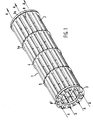
- fig. 1 represents a view of an embodiment of the invention
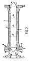
- Fig. 2 shows a longitudinal section of the embodiment of fig. 1.
- the system 1 is provided with flanges 3, 3a at its ends. In this way the system is adapted to be mounted into a flow line (not shown), for example, by suitable connecting means 6 and an adapting means 7 (shown in fig. 2. in relation to the flange 3 only).
- the system is further provided with exciting means adapted to vibrate the system of tubes at 50X of their lengths.
- the exciting means are not represented for the sake of clarity.
- the system is further provided with distortion detecting means (not represented for the sake of clarity). These means are provided at 25% and 75% of the tube lengths respectively.
- each tube has an inner diameter of about 20 mm and a wall thickness of about 0.5 mm.
- the tubes 2 are fixed together at the exciting point 4 and detecting points 5, 5a respectively and can be considered as one single tube.
- the operation of the system is as follows:
- the system is excited at 50X of its length to give it a vibration in a direction normal to the flow direction.
- the flow direction is represented by the arrows A. Only a few arrows A have been represented for reasons of clarity.
- the amplitude of the transversal vibration of each fluid particle will increase, whereas in the second half (i.e. the downstream part) of the tube it will decrease.
- Coriolis force The interaction between fluid and tube wall yields a force acting on the tube wall, which is known as the "Coriolis force”.
- Coriolis force is known to those skilled in the art and will not be explained in further detail.
- the Coriolis force tends to slow down the vibration of the tube, since energy has to be stored in the vibration of the fluid, but in the second half of the tube the Coriolis force tends to stimulate the vibration: the energy is released again from the fluid.
- the phase of the oscillation of the various points of the tubes is no longer equal.
- the upstream part of the tubes has a phase lag, whereas the downstream part leads in phase.
- the distortion allows the distortion to be measured in a simple way: the oscillating motions of the upstream and downstream parts of the tubes are detected by mounting suitable detectors, for example accelerometers, on the tubes, at about 25 and 75X of the tube lengths respectively.
- suitable detectors for example accelerometers
- phase difference or time lag between these two (sinusoidal) signals is now proportional to the mass flow through the tube.
- a variety of methods for measuring this phase difference is known to those skilled in the art and will not be described in detail.
- system of tubes may comprise any number of parallel-straight tubes suitable for the purpose, provided that this number is at least two.
- the number of tubes is 3-24.
- tubes of any length and diameter suitable for the purpose can be used.
- the length-to-inner diameter ratio is larger than 50.
- the advantage of the use of tubes having a large length-to-inner diameter ratio is the increased sensitivity of the apparatus.
- the tubes may be vibrating in antiphase.
- the advantage of the above two ways of vibration is the balance of motion.
- each individual tube always performs a linear vibration.
- Such a mode of vibration may be advantageous in multiphase flow, if the residence time of the individual fluid particles in the tube might not cover a sufficiently large number of periods of the vibration to ensure proper measurement.
- the tubes may consist of any material suitable for the purpose.
- any suitable exciting means and any suitable detecting means may be used.
Abstract
Description
- The invention relates to a Coriolis-type mass flow meter and, in particular, to such a meter comprising at least two straight parallel vibrating tubes.
- These meters can be used, in particular, for the monitoring of multi-phase flows in flow lines. Coriolis-type mass flow meters comprising one straight vibrating tube are already known. These meters are based upon the following principle:
- The flow to be measured flows through a straight tube which is part of a flow line. The ends of the tube are clamped. The tube itself is adapted to be excited at 50% of its length and vibrates at or near its resonance frequency.
- A mass flow through the tube causes distortion of this forced vibration and a phase'difference to occur between the upstream and downstream part of the tube, which is proportional to mass flow. The theoretical relations between mass flow rate and phase difference are known to those skilled in the art and will not be explained in detail.
- The length of the meter is a critical parameter: the meter sensitivity increases proportionally to the total tube length and in multi-phase flow a minimum length-to-inner diameter ratio is required.
- However, for practical applications the length of the meter should be limited and therefore the diameter of the vibrating tube must be reduced with respect to the flow line diameter.
- However, this results in too high a pressure loss of the meter, which may cause serious measuring problems.
- It is therefore an object of the invention to provide a Coriolis-type mass flow meter of restricted length, which is suitable to be used for monitoring multiphase-flow and can be handled easily.
- The invention therefore provides a Coriolis-type mass flow meter to be used in a flowline, said meter comprising a flow means for having a fluid flow therethrough, characterized in that said flow means is adapted to be vibrated by an exciting means at 50X of the length of the flow means in a direction normal to the flow direction, and comprising means adapted to detect the phase difference occurring between upstream and downstream parts of the flow means, at equal distances from the exciting means, when subjected to vibration at a certain frequency, and means adapted to connect the flow means to the flow line, wherein said flow means comprises at least two straight parallel tubes.
- In an advantageous embodiment of the invention the mass flow meter is adapted to be used horizontally in a flow line. In another advantageous embodiment the mass flow meter is adapted to be used vertically in a flow line.
- The invention will now be described by way of example in more detail by reference to the accompanying drawings in which fig. 1 represents a view of an embodiment of the invention; and Fig. 2 shows a longitudinal section of the embodiment of fig. 1.
- With reference now to the drawings the figures show a system 1 of 16 parallel
straight tubes 2. - The system 1 is provided with
flanges 3, 3a at its ends. In this way the system is adapted to be mounted into a flow line (not shown), for example, by suitable connecting means 6 and an adapting means 7 (shown in fig. 2. in relation to the flange 3 only). - The system is further provided with exciting means adapted to vibrate the system of tubes at 50X of their lengths. The exciting means are not represented for the sake of clarity.
- The system is further provided with distortion detecting means (not represented for the sake of clarity). These means are provided at 25% and 75% of the tube lengths respectively.
- In this embodiment the tubes have lengths of about 0.90 meter; each tube has an inner diameter of about 20 mm and a wall thickness of about 0.5 mm.
- In the figures the
tubes 2 are fixed together at the exciting point 4 and detectingpoints - The system of tubes is mounted in the flowline in any way suitable for the purpose. The space B-B1 between the
tubes 2 is closed by any means suitable for the purpose (not shown for reasons of clarity). A fluid is flowing through all separateparallel tubes 2 of the system 1 by any means suitable for the purpose, for example a pump (not shown). The mounting of the system in the flow line is carried out in such a way, that the mounted system has clamped ends. (not shown) - The system is excited at 50X of its length to give it a vibration in a direction normal to the flow direction. The flow direction is represented by the arrows A. Only a few arrows A have been represented for reasons of clarity. When the fluid flows through the tube-system 1, the fluid particles are forced to follow the transversal vibration of the tube walls.
- In the first half of the tube, i.e. the upstream part, the amplitude of the transversal vibration of each fluid particle will increase, whereas in the second half (i.e. the downstream part) of the tube it will decrease.
- The interaction between fluid and tube wall yields a force acting on the tube wall, which is known as the "Coriolis force". The term "Coriolis force" is known to those skilled in the art and will not be explained in further detail.
- In the first half of the tube the Coriolis force tends to slow down the vibration of the tube, since energy has to be stored in the vibration of the fluid, but in the second half of the tube the Coriolis force tends to stimulate the vibration: the energy is released again from the fluid.
- The result is that the flow of a fluid through the tubes yields a S-shaped distortion of the tubes, the amplitude of which is proportional to the mass flow rate.
- Since the distortion occurs in a system vibrating at a certain frequency, the phase of the oscillation of the various points of the tubes is no longer equal. The upstream part of the tubes has a phase lag, whereas the downstream part leads in phase.
- This consequence of the distortion allows the distortion to be measured in a simple way: the oscillating motions of the upstream and downstream parts of the tubes are detected by mounting suitable detectors, for example accelerometers, on the tubes, at about 25 and 75X of the tube lengths respectively.
- The phase difference or time lag between these two (sinusoidal) signals is now proportional to the mass flow through the tube. A variety of methods for measuring this phase difference is known to those skilled in the art and will not be described in detail.
- It will be appreciated that the system of tubes may comprise any number of parallel-straight tubes suitable for the purpose, provided that this number is at least two.
- In advantageous embodiments of the invention the number of tubes is 3-24.
- It will further be appreciated that tubes of any length and diameter suitable for the purpose can be used. In an advantageous embodiment of the invention the length-to-inner diameter ratio is larger than 50. The advantage of the use of tubes having a large length-to-inner diameter ratio is the increased sensitivity of the apparatus.
- It will also be appreciated that several ways of arranging the tubes of the system and modes of vibrating the tubes are possible:
- for example a bundle of tubes or a horizontal row of tubes, which are vibrated in a vertical direction or a system of tubes arranged in a circle with rotating vibration.
- In case of two parallel tubes, the tubes may be vibrating in antiphase. The advantage of the above two ways of vibration is the balance of motion.
- In the above-mentioned embodiments each individual tube always performs a linear vibration.
- However, it will be appreciated that a circular translation of the tube or bundle of tubes may be carried out.
- This can be done by combining two linear vibrations - one horizontally, the other vertically, and 90° out of phase.
- Such a mode of vibration may be advantageous in multiphase flow, if the residence time of the individual fluid particles in the tube might not cover a sufficiently large number of periods of the vibration to ensure proper measurement.
- It will be appreciated that the tubes may consist of any material suitable for the purpose.
- It will further be appreciated that any suitable exciting means and any suitable detecting means may be used.
- Further the tubes need not be necessarily fixed at the exciting and detecting points. Various modifications of the invention will become apparent to those skilled in the art from the foregoing description and accompanying drawings.
- Such modifications are intended to fall within the scope of the appended claims.
Claims (10)
Applications Claiming Priority (2)
| Application Number | Priority Date | Filing Date | Title |
|---|---|---|---|
| GB838304783A GB8304783D0 (en) | 1983-02-21 | 1983-02-21 | Coriolis-type mass flow meter |
| GB8304783 | 1983-02-21 |
Publications (2)
| Publication Number | Publication Date |
|---|---|
| EP0119638A1 true EP0119638A1 (en) | 1984-09-26 |
| EP0119638B1 EP0119638B1 (en) | 1987-04-22 |
Family
ID=10538350
Family Applications (1)
| Application Number | Title | Priority Date | Filing Date |
|---|---|---|---|
| EP84200115A Expired EP0119638B1 (en) | 1983-02-21 | 1984-01-30 | Coriolis-type mass flow meter comprising at least two straight parallel vibrating tubes |
Country Status (6)
| Country | Link |
|---|---|
| US (1) | US5048349A (en) |
| EP (1) | EP0119638B1 (en) |
| JP (1) | JPS59162416A (en) |
| CA (1) | CA1205653A (en) |
| DE (1) | DE3463298D1 (en) |
| GB (1) | GB8304783D0 (en) |
Cited By (38)
| Publication number | Priority date | Publication date | Assignee | Title |
|---|---|---|---|---|
| DE3443234A1 (en) * | 1984-11-27 | 1986-06-05 | Danfoss A/S, Nordborg | MASS FLOW MEASURING DEVICE ACCORDING TO THE CORIOLIS PRINCIPLE |
| GB2171200A (en) * | 1985-02-15 | 1986-08-20 | Danfoss As | Mass flow meters making use of coriolis effects |
| EP0196150A1 (en) * | 1985-03-25 | 1986-10-01 | International Control Automation Finance S.A. | Fluid flow measurement |
| GB2181242A (en) * | 1985-09-26 | 1987-04-15 | Danfoss As | Coriolis mass flow meters |
| US4703660A (en) * | 1986-04-01 | 1987-11-03 | The Babcock & Wilcox Company | Apparatus and method for continuously measuring mass flow |
| FR2598801A1 (en) * | 1986-05-13 | 1987-11-20 | Assistance Indle Dauphinoise A | Mass flowmeter with multimode elasticity |
| WO1987007714A1 (en) * | 1986-06-10 | 1987-12-17 | The Foxboro Company | Coriolis mass flowmeters |
| EP0253504A1 (en) * | 1986-07-16 | 1988-01-20 | Schlumberger Industries Limited | Mass flowmeter |
| US4730501A (en) * | 1986-05-19 | 1988-03-15 | Exac Corporation | Single tube parallel flow coriolis mass flow sensor |
| EP0261436A2 (en) * | 1986-09-26 | 1988-03-30 | Endress + Hauser Flowtec AG | Mass flow meter according to the Coriolis principle |
| EP0282217A2 (en) * | 1987-03-11 | 1988-09-14 | Schlumberger Industries Limited | Mass flow measurement |
| US4879910A (en) * | 1987-07-10 | 1989-11-14 | Lew Hyok S | Torsional vibration convective inertia force flowmeter |
| US4949583A (en) * | 1987-11-20 | 1990-08-21 | Flowtec Ag | Method of mass flow measurement by the coriolis principle and mass flow meter operating by the coriolis principle |
| US4972724A (en) * | 1988-07-15 | 1990-11-27 | Fischer & Porter Company | Coriolis-type mass flowmeter having a straight measuring tube |
| DE4016907A1 (en) * | 1990-05-25 | 1991-11-28 | Krohne Messtechnik Massametron | Mass flow measurement arrangement for flowing medium - contains three section chamber with vibration generator(s) acting on central section, detector of coriolis forces or vibrations |
| DE4124296A1 (en) * | 1990-07-28 | 1992-02-06 | Krohne Messtechnik Massametron | Mass flow measurement arrangement with vibration generator |
| US5090253A (en) * | 1990-05-14 | 1992-02-25 | Atlantic Richfield Company | Coriolis type fluid flowmeter |
| US5226330A (en) * | 1991-10-31 | 1993-07-13 | Lew Hyok S | High sensitivity mass flowmeter |
| DE4224379C1 (en) * | 1992-07-06 | 1993-12-23 | Krohne Messtechnik Kg | Mass flow meter |
| US5473949A (en) * | 1991-02-05 | 1995-12-12 | Direct Measurement Corporation | Coriolis mass flow rate meter having adjustable pressure and density sensitivity |
| EP0687893A2 (en) | 1991-07-22 | 1995-12-20 | Krohne AG | Mass flow rate measuring apparatus |
| EP0691528A2 (en) | 1994-07-04 | 1996-01-10 | Krohne AG | Mass flowmeter |
| EP0706032A1 (en) | 1994-10-07 | 1996-04-10 | Krohne Messtechnik Gmbh & Co. Kg | Measuring apparatus for flowing fluids |
| US5576500A (en) * | 1991-02-05 | 1996-11-19 | Direct Measurement Corporation | Coriolis mass flow rate meter having means for modifying angular velocity gradient positioned within a conduit |
| US5753827A (en) * | 1995-10-17 | 1998-05-19 | Direct Measurement Corporation | Coriolis meteR having a geometry insensitive to changes in fluid pressure and density and method of operation thereof |
| US5827979A (en) * | 1996-04-22 | 1998-10-27 | Direct Measurement Corporation | Signal processing apparati and methods for attenuating shifts in zero intercept attributable to a changing boundary condition in a Coriolis mass flow meter |
| US5907104A (en) * | 1995-12-08 | 1999-05-25 | Direct Measurement Corporation | Signal processing and field proving methods and circuits for a coriolis mass flow meter |
| US6227059B1 (en) | 1999-01-12 | 2001-05-08 | Direct Measurement Corporation | System and method for employing an imaginary difference signal component to compensate for boundary condition effects on a Coriolis mass flow meter |
| DE10351312B4 (en) * | 2003-10-31 | 2009-05-07 | Abb Ag | Attachment and Coriolis mass flow meter with this attachment |
| EP2159552A1 (en) * | 2008-08-27 | 2010-03-03 | Krohne AG | Mass flow rate measuring device |
| WO2010102999A1 (en) * | 2009-03-11 | 2010-09-16 | Endress+Hauser Flowtec Ag | Vibration sensor and in-line measuring device comprising said sensor |
| WO2010103077A1 (en) * | 2009-03-11 | 2010-09-16 | Endress+Hauser Flowtec Ag | Vibration sensor and in-line measuring device comprising said sensor |
| US7843199B2 (en) | 2007-01-31 | 2010-11-30 | Krohne S.A. | Level meter |
| DE102009055069A1 (en) * | 2009-12-21 | 2011-06-22 | Endress + Hauser Flowtec Ag | Vibration-type measuring sensor for detecting e.g. mass flow rate of gas and for producing Coriolis forces in process measurement- and automation system, has tube arrangement exhibiting sectional plane running between measuring tubes |
| US8327719B2 (en) | 2009-03-11 | 2012-12-11 | Endress + Hauser Flowtec Ag | Measuring transducer of vibration-type, as well as an in-line measuring device having such a measuring transducer |
| WO2012150241A3 (en) * | 2011-05-02 | 2013-01-10 | Endress+Hauser Flowtec Ag | Vibration-type measuring sensor and measuring system formed therewith |
| US8613227B2 (en) | 2009-12-21 | 2013-12-24 | Endress + Hauser Flowtec Ag | Measuring transducer of vibration-type with four curved measuring tubes |
| WO2017164891A1 (en) * | 2016-03-25 | 2017-09-28 | Micro Motion, Inc. | Method for maximizing flowmeter turndown and related apparatus |
Families Citing this family (13)
| Publication number | Priority date | Publication date | Assignee | Title |
|---|---|---|---|---|
| JPS62170819A (en) * | 1986-01-23 | 1987-07-27 | Oval Eng Co Ltd | Mass flow meter |
| US5297426A (en) * | 1993-04-07 | 1994-03-29 | Abb K-Flow Inc. | Hydrodynamic fluid divider for fluid measuring devices |
| US5691485A (en) * | 1994-06-06 | 1997-11-25 | Oval Corporation | Coaxial double tube type Coriolis flowmeter |
| US5969264A (en) * | 1998-11-06 | 1999-10-19 | Technology Commercialization Corp. | Method and apparatus for total and individual flow measurement of a single-or multi-phase medium |
| US6688176B2 (en) * | 2000-01-13 | 2004-02-10 | Halliburton Energy Services, Inc. | Single tube densitometer |
| US6378364B1 (en) | 2000-01-13 | 2002-04-30 | Halliburton Energy Services, Inc. | Downhole densitometer |
| US6553845B2 (en) * | 2000-05-19 | 2003-04-29 | Kazumasa Ohnishi | Coriolis flowmeter utilizing three-forked plate vibrator mode |
| US7299705B2 (en) * | 2003-07-15 | 2007-11-27 | Cidra Corporation | Apparatus and method for augmenting a Coriolis meter |
| US7389687B2 (en) * | 2004-11-05 | 2008-06-24 | Cidra Corporation | System for measuring a parameter of an aerated multi-phase mixture flowing in a pipe |
| US7690266B2 (en) | 2008-04-02 | 2010-04-06 | Expro Meters, Inc. | Process fluid sound speed determined by characterization of acoustic cross modes |
| WO2011123040A1 (en) * | 2010-03-31 | 2011-10-06 | Ge Healthcare Bio-Sciences Ab | A parallel separation system |
| DE102010047241B4 (en) * | 2010-10-04 | 2015-08-06 | Krohne Ag | Coriolis mass flowmeter |
| MX2016016829A (en) * | 2014-07-23 | 2017-03-27 | Halliburton Energy Services Inc | Thermal modulated vibrating sensing module for gas molecular weight detection. |
Citations (4)
| Publication number | Priority date | Publication date | Assignee | Title |
|---|---|---|---|---|
| US2821084A (en) * | 1954-09-07 | 1958-01-28 | American Radiator & Standard | Flow control devices for flowmeters |
| US4109524A (en) * | 1975-06-30 | 1978-08-29 | S & F Associates | Method and apparatus for mass flow rate measurement |
| US4252028A (en) * | 1979-02-26 | 1981-02-24 | S & F Associates | Method and apparatus for measuring flow |
| US4311054A (en) * | 1978-11-13 | 1982-01-19 | Halliburton Company | Mass flowmeter with sensor gain control |
Family Cites Families (18)
| Publication number | Priority date | Publication date | Assignee | Title |
|---|---|---|---|---|
| DE268353C (en) * | 1947-09-02 | |||
| US3080750A (en) * | 1959-01-09 | 1963-03-12 | Bendix Corp | Oscillating mass flowmeter |
| US3276257A (en) * | 1960-02-02 | 1966-10-04 | Roth Wilfred | Gyroscopic mass flowmeters |
| US3218851A (en) * | 1961-05-24 | 1965-11-23 | Anatole J Sipin | Mass flowmeter systems |
| US3485098A (en) * | 1964-09-03 | 1969-12-23 | Anatole J Sipin | Mass flow metering means |
| US3355944A (en) * | 1964-09-03 | 1967-12-05 | Anatole J Sipin | Mass flow metering means |
| US3329019A (en) * | 1964-10-26 | 1967-07-04 | Anatole J Sipin | Mass flow metering means |
| FR1472039A (en) * | 1965-05-28 | 1967-03-10 | Gaz De France | Fluid mass flow meter |
| GB1158790A (en) * | 1965-12-29 | 1969-07-16 | Solartron Electronic Group | Improvements in Fluid Density Meters |
| GB1207997A (en) * | 1966-10-22 | 1970-10-07 | Siegfried Brockhaus | Device for measuring the density of a fluid |
| US4127028A (en) * | 1977-06-07 | 1978-11-28 | Halliburton Company | Coriolis mass flow rate metering means |
| US4187721A (en) * | 1977-07-25 | 1980-02-12 | S & F Associates | Method and structure for flow measurement |
| JPS57137818A (en) * | 1981-02-19 | 1982-08-25 | Tokyo Keiki Co Ltd | Straight tube type mass flowmeter |
| JPS58161828A (en) * | 1982-03-22 | 1983-09-26 | Nippon Steel Corp | Method for detecting metal position |
| JPS58120122A (en) * | 1982-01-13 | 1983-07-16 | Yokogawa Hokushin Electric Corp | Mass flowmeter |
| US4491025A (en) * | 1982-11-03 | 1985-01-01 | Micro Motion, Inc. | Parallel path Coriolis mass flow rate meter |
| US4616509A (en) * | 1985-01-15 | 1986-10-14 | Feller Murray F | Flow detectors |
| US4622858A (en) * | 1985-03-25 | 1986-11-18 | The Babcock & Wilcox Company | Apparatus and method for continuously measuring mass flow |
-
1983
- 1983-02-21 GB GB838304783A patent/GB8304783D0/en active Pending
-
1984
- 1984-01-30 EP EP84200115A patent/EP0119638B1/en not_active Expired
- 1984-01-30 DE DE8484200115T patent/DE3463298D1/en not_active Expired
- 1984-01-31 CA CA000446440A patent/CA1205653A/en not_active Expired
- 1984-02-20 JP JP59030119A patent/JPS59162416A/en active Granted
-
1987
- 1987-05-21 US US07/058,667 patent/US5048349A/en not_active Expired - Lifetime
Patent Citations (4)
| Publication number | Priority date | Publication date | Assignee | Title |
|---|---|---|---|---|
| US2821084A (en) * | 1954-09-07 | 1958-01-28 | American Radiator & Standard | Flow control devices for flowmeters |
| US4109524A (en) * | 1975-06-30 | 1978-08-29 | S & F Associates | Method and apparatus for mass flow rate measurement |
| US4311054A (en) * | 1978-11-13 | 1982-01-19 | Halliburton Company | Mass flowmeter with sensor gain control |
| US4252028A (en) * | 1979-02-26 | 1981-02-24 | S & F Associates | Method and apparatus for measuring flow |
Cited By (73)
| Publication number | Priority date | Publication date | Assignee | Title |
|---|---|---|---|---|
| DE3443234A1 (en) * | 1984-11-27 | 1986-06-05 | Danfoss A/S, Nordborg | MASS FLOW MEASURING DEVICE ACCORDING TO THE CORIOLIS PRINCIPLE |
| FR2575824A1 (en) * | 1984-11-27 | 1986-07-11 | Danfoss As | MASS FLOW MEASUREMENT APPARATUS ACCORDING TO THE CORIOLIS PRINCIPLE |
| GB2171200A (en) * | 1985-02-15 | 1986-08-20 | Danfoss As | Mass flow meters making use of coriolis effects |
| DE3505166A1 (en) * | 1985-02-15 | 1986-08-21 | Danfoss A/S, Nordborg | MASS FLOW MEASURING DEVICE ACCORDING TO THE CORIOLIS PRINCIPLE |
| US4680974A (en) * | 1985-02-15 | 1987-07-21 | Danfoss A/S | Mass flow meter on the coriolis principle |
| EP0196150A1 (en) * | 1985-03-25 | 1986-10-01 | International Control Automation Finance S.A. | Fluid flow measurement |
| AU585326B2 (en) * | 1985-03-25 | 1989-06-15 | International Control Automation Finance Sa | Apparatus and method for continuously measuring mass flow |
| EP0196150B1 (en) | 1985-03-25 | 1990-11-07 | International Control Automation Finance S.A. | Fluid flow measurement |
| GB2181242A (en) * | 1985-09-26 | 1987-04-15 | Danfoss As | Coriolis mass flow meters |
| FR2591740A1 (en) * | 1985-09-26 | 1987-06-19 | Danfoss As | APPARATUS FOR MEASURING MASS FLOW IN ACCORDANCE WITH THE CORIOLIS PRINCIPLE |
| GB2181242B (en) * | 1985-09-26 | 1990-04-18 | Danfoss As | Mass flow meters operating on the coriolis principle |
| US4703660A (en) * | 1986-04-01 | 1987-11-03 | The Babcock & Wilcox Company | Apparatus and method for continuously measuring mass flow |
| FR2598801A1 (en) * | 1986-05-13 | 1987-11-20 | Assistance Indle Dauphinoise A | Mass flowmeter with multimode elasticity |
| US4730501A (en) * | 1986-05-19 | 1988-03-15 | Exac Corporation | Single tube parallel flow coriolis mass flow sensor |
| WO1987007714A1 (en) * | 1986-06-10 | 1987-12-17 | The Foxboro Company | Coriolis mass flowmeters |
| US4934195A (en) * | 1986-06-10 | 1990-06-19 | The Foxboro Company | Coriolis mass flowmeter |
| EP0253504A1 (en) * | 1986-07-16 | 1988-01-20 | Schlumberger Industries Limited | Mass flowmeter |
| US4793191A (en) * | 1986-09-26 | 1988-12-27 | Flowtec Ag | Mass flow meter operating by the cariolis principle |
| EP0261436B1 (en) * | 1986-09-26 | 1991-12-04 | Endress + Hauser Flowtec AG | Mass flow meter according to the coriolis principle |
| EP0261436A2 (en) * | 1986-09-26 | 1988-03-30 | Endress + Hauser Flowtec AG | Mass flow meter according to the Coriolis principle |
| DE3632851A1 (en) * | 1986-09-26 | 1988-04-07 | Flowtec Ag | MASS FLOW MEASURING DEVICE WORKING ACCORDING TO THE CORIOLIS PRINCIPLE |
| EP0282217A2 (en) * | 1987-03-11 | 1988-09-14 | Schlumberger Industries Limited | Mass flow measurement |
| EP0282217A3 (en) * | 1987-03-11 | 1989-08-23 | Schlumberger Industries Limited | Mass flow measurement |
| US4879910A (en) * | 1987-07-10 | 1989-11-14 | Lew Hyok S | Torsional vibration convective inertia force flowmeter |
| US4949583A (en) * | 1987-11-20 | 1990-08-21 | Flowtec Ag | Method of mass flow measurement by the coriolis principle and mass flow meter operating by the coriolis principle |
| US4972724A (en) * | 1988-07-15 | 1990-11-27 | Fischer & Porter Company | Coriolis-type mass flowmeter having a straight measuring tube |
| US5090253A (en) * | 1990-05-14 | 1992-02-25 | Atlantic Richfield Company | Coriolis type fluid flowmeter |
| DE4016907A1 (en) * | 1990-05-25 | 1991-11-28 | Krohne Messtechnik Massametron | Mass flow measurement arrangement for flowing medium - contains three section chamber with vibration generator(s) acting on central section, detector of coriolis forces or vibrations |
| DE4016907C3 (en) * | 1990-05-25 | 1998-06-10 | Krohne Ag | Mass flow meter |
| DE4124296A1 (en) * | 1990-07-28 | 1992-02-06 | Krohne Messtechnik Massametron | Mass flow measurement arrangement with vibration generator |
| US5473949A (en) * | 1991-02-05 | 1995-12-12 | Direct Measurement Corporation | Coriolis mass flow rate meter having adjustable pressure and density sensitivity |
| US5576500A (en) * | 1991-02-05 | 1996-11-19 | Direct Measurement Corporation | Coriolis mass flow rate meter having means for modifying angular velocity gradient positioned within a conduit |
| EP0687893A2 (en) | 1991-07-22 | 1995-12-20 | Krohne AG | Mass flow rate measuring apparatus |
| US5226330A (en) * | 1991-10-31 | 1993-07-13 | Lew Hyok S | High sensitivity mass flowmeter |
| EP0775893A2 (en) | 1992-07-06 | 1997-05-28 | Krohne Messtechnik Gmbh & Co. Kg | Mass flowrate measuring device |
| DE4224379C2 (en) * | 1992-07-06 | 1998-05-20 | Krohne Messtechnik Kg | Mass flow meter |
| DE4224379C1 (en) * | 1992-07-06 | 1993-12-23 | Krohne Messtechnik Kg | Mass flow meter |
| EP0691528A2 (en) | 1994-07-04 | 1996-01-10 | Krohne AG | Mass flowmeter |
| EP0706032A1 (en) | 1994-10-07 | 1996-04-10 | Krohne Messtechnik Gmbh & Co. Kg | Measuring apparatus for flowing fluids |
| US5753827A (en) * | 1995-10-17 | 1998-05-19 | Direct Measurement Corporation | Coriolis meteR having a geometry insensitive to changes in fluid pressure and density and method of operation thereof |
| US5907104A (en) * | 1995-12-08 | 1999-05-25 | Direct Measurement Corporation | Signal processing and field proving methods and circuits for a coriolis mass flow meter |
| US5827979A (en) * | 1996-04-22 | 1998-10-27 | Direct Measurement Corporation | Signal processing apparati and methods for attenuating shifts in zero intercept attributable to a changing boundary condition in a Coriolis mass flow meter |
| US6227059B1 (en) | 1999-01-12 | 2001-05-08 | Direct Measurement Corporation | System and method for employing an imaginary difference signal component to compensate for boundary condition effects on a Coriolis mass flow meter |
| DE10351312B4 (en) * | 2003-10-31 | 2009-05-07 | Abb Ag | Attachment and Coriolis mass flow meter with this attachment |
| US7843199B2 (en) | 2007-01-31 | 2010-11-30 | Krohne S.A. | Level meter |
| EP2159552A1 (en) * | 2008-08-27 | 2010-03-03 | Krohne AG | Mass flow rate measuring device |
| US7946187B2 (en) | 2008-08-27 | 2011-05-24 | Krohne Ag | Mass flowmeter |
| US8347736B2 (en) | 2009-03-11 | 2013-01-08 | Endress + Hauser Flowtec Ag | Measuring transducer of vibration-type, as well as an in-line measuring device having such a measuring transducer |
| US8333121B2 (en) | 2009-03-11 | 2012-12-18 | Endress + Hauser Flowtec Ag | Measuring system for media flowing in a pipeline |
| WO2010103080A1 (en) * | 2009-03-11 | 2010-09-16 | Endress+Hauser Flowtec Ag | Measuring system for media which flow in a tube conduit |
| WO2010103079A1 (en) * | 2009-03-11 | 2010-09-16 | Endress+Hauser Flowtec Ag | Vibration sensor and in-line measuring device comprising said sensor |
| WO2010103076A1 (en) * | 2009-03-11 | 2010-09-16 | Endress+Hauser Flowtec Ag | Vibration sensor and in-line measuring device comprising said sensor |
| WO2010103077A1 (en) * | 2009-03-11 | 2010-09-16 | Endress+Hauser Flowtec Ag | Vibration sensor and in-line measuring device comprising said sensor |
| CN102348962B (en) * | 2009-03-11 | 2015-12-02 | 恩德斯+豪斯流量技术股份有限公司 | Oscillatory type measurement transducer and there is the on-line measurement device of this measurement transducer |
| CN102348960A (en) * | 2009-03-11 | 2012-02-08 | 恩德斯+豪斯流量技术股份有限公司 | Vibration sensor and in-line measuring device comprising said sensor |
| CN102348962A (en) * | 2009-03-11 | 2012-02-08 | 恩德斯+豪斯流量技术股份有限公司 | Vibration sensor and in-line measuring device comprising said sensor |
| CN102348961A (en) * | 2009-03-11 | 2012-02-08 | 恩德斯+豪斯流量技术股份有限公司 | Measuring system for media which flow in a tube conduit |
| US8327719B2 (en) | 2009-03-11 | 2012-12-11 | Endress + Hauser Flowtec Ag | Measuring transducer of vibration-type, as well as an in-line measuring device having such a measuring transducer |
| US8333119B2 (en) | 2009-03-11 | 2012-12-18 | Endress + Hauser Flowtec Ag | Measuring transducer of vibration-type, as well as an in-line measuring device having such a measuring transducer |
| US8333120B2 (en) | 2009-03-11 | 2012-12-18 | Endress + Hauser Flowtec Ag | Measuring transducer of vibration-type, as well as an in-line measuring device having such a measuring transducer |
| WO2010103078A1 (en) * | 2009-03-11 | 2010-09-16 | Endress+Hauser Flowtec Ag | Vibration sensor and in-line measuring device comprising said sensor |
| US8336396B2 (en) | 2009-03-11 | 2012-12-25 | Endress + Hauser Flowtec Ag | Measuring transducer of vibration-type, as well as an in-line measuring device having such a measuring transducer |
| WO2010102999A1 (en) * | 2009-03-11 | 2010-09-16 | Endress+Hauser Flowtec Ag | Vibration sensor and in-line measuring device comprising said sensor |
| CN102348961B (en) * | 2009-03-11 | 2015-04-22 | 恩德斯+豪斯流量技术股份有限公司 | Measuring system for media which flow in a tube conduit |
| RU2492430C2 (en) * | 2009-03-11 | 2013-09-10 | Эндресс + Хаузер Флоутек Аг | Vibratory sensor, and flow monitoring and metering instrument with said sensor |
| CN102348960B (en) * | 2009-03-11 | 2013-11-13 | 恩德斯+豪斯流量技术股份有限公司 | Vibration sensor and in-line measuring device comprising the sensor |
| US8613227B2 (en) | 2009-12-21 | 2013-12-24 | Endress + Hauser Flowtec Ag | Measuring transducer of vibration-type with four curved measuring tubes |
| US8695436B2 (en) | 2009-12-21 | 2014-04-15 | Endress + Hauser Flowtec Ag | Measuring transducer of vibration-type with four curved measuring tubes |
| DE102009055069A1 (en) * | 2009-12-21 | 2011-06-22 | Endress + Hauser Flowtec Ag | Vibration-type measuring sensor for detecting e.g. mass flow rate of gas and for producing Coriolis forces in process measurement- and automation system, has tube arrangement exhibiting sectional plane running between measuring tubes |
| US9410835B2 (en) | 2009-12-21 | 2016-08-09 | Endress + Hauser Flowtec Ag | Measuring transducer of vibration-type with four curved measuring tubes |
| US8863589B2 (en) | 2011-05-02 | 2014-10-21 | Endress + Hauser Flowtec Ag | Measuring transducer of vibration type and measuring system |
| WO2012150241A3 (en) * | 2011-05-02 | 2013-01-10 | Endress+Hauser Flowtec Ag | Vibration-type measuring sensor and measuring system formed therewith |
| WO2017164891A1 (en) * | 2016-03-25 | 2017-09-28 | Micro Motion, Inc. | Method for maximizing flowmeter turndown and related apparatus |
Also Published As
| Publication number | Publication date |
|---|---|
| GB8304783D0 (en) | 1983-03-23 |
| JPS59162416A (en) | 1984-09-13 |
| US5048349A (en) | 1991-09-17 |
| JPH0462006B2 (en) | 1992-10-02 |
| EP0119638B1 (en) | 1987-04-22 |
| CA1205653A (en) | 1986-06-10 |
| DE3463298D1 (en) | 1987-05-27 |
Similar Documents
| Publication | Publication Date | Title |
|---|---|---|
| EP0119638A1 (en) | Coriolis-type mass flow meter comprising at least two straight parallel vibrating tubes | |
| JP2859591B2 (en) | Coriolis mass flow detector | |
| CN107110686B (en) | Vibration-type measuring transducer and measuring system formed by same | |
| AU2007354291B2 (en) | Vibratory flow meter and method for correcting for entrained gas in a flow material | |
| US5969264A (en) | Method and apparatus for total and individual flow measurement of a single-or multi-phase medium | |
| CA2184751C (en) | Increased sensitivity coriolis effect flowmeter using nodal-proximate sensors | |
| RU2460973C2 (en) | Vibration flow meter for determining one or more parameters of multiphase flowing fluid | |
| AU2007362570B2 (en) | A vibrating flow device and method for fabricating a vibrating flow device | |
| RU2012131135A (en) | VIBRATION TYPE MEASURING SENSOR, METHOD OF MANUFACTURING THE MEASURING SENSOR AND MEASURING SYSTEM, APPLICATION OF THE MEASURING SENSOR | |
| JPH06509649A (en) | Coriolis effect mass flowmeter | |
| WO1987007714A1 (en) | Coriolis mass flowmeters | |
| KR100987103B1 (en) | Method and apparatus for force balancing | |
| US5048351A (en) | Mass flow sensor | |
| CA2590807C (en) | Vibratory measurement transducer | |
| US11187564B2 (en) | Vibratory flow meter with multichannel flow tube | |
| CN111492211B (en) | Vibration-type measuring transducer and vibration measuring system formed by same | |
| US10018491B2 (en) | Vibrating sensor assembly with a one-piece conduit mount | |
| WO2005073676A1 (en) | Flow unit for a coriolis type mass flow meter | |
| JPH0341319A (en) | Coriolis mass flowmeter | |
| JPS62170819A (en) | Mass flow meter | |
| SU1765698A1 (en) | Mass vibrational flowmeter | |
| WO2024072431A1 (en) | Flowmeter magnetic shielding apparatus and method | |
| RU2427804C1 (en) | Vibratory flow metre and procedure for introduction of correction for entrained gas in flowing material | |
| JPS6291815A (en) | Method for measuring phase mass in multiphase flow |
Legal Events
| Date | Code | Title | Description |
|---|---|---|---|
| PUAI | Public reference made under article 153(3) epc to a published international application that has entered the european phase |
Free format text: ORIGINAL CODE: 0009012 |
|
| 17P | Request for examination filed |
Effective date: 19840130 |
|
| AK | Designated contracting states |
Designated state(s): DE FR GB NL |
|
| 17Q | First examination report despatched |
Effective date: 19860410 |
|
| GRAA | (expected) grant |
Free format text: ORIGINAL CODE: 0009210 |
|
| AK | Designated contracting states |
Kind code of ref document: B1 Designated state(s): DE FR GB NL |
|
| REF | Corresponds to: |
Ref document number: 3463298 Country of ref document: DE Date of ref document: 19870527 |
|
| ET | Fr: translation filed | ||
| PLBI | Opposition filed |
Free format text: ORIGINAL CODE: 0009260 |
|
| PLBI | Opposition filed |
Free format text: ORIGINAL CODE: 0009260 |
|
| PLBI | Opposition filed |
Free format text: ORIGINAL CODE: 0009260 |
|
| 26 | Opposition filed |
Opponent name: DANFOSS A/S Effective date: 19871211 |
|
| 26 | Opposition filed |
Opponent name: DANFOSS A/S Effective date: 19871211 Opponent name: ENDRESS+HAUSER GMBH+CO. Effective date: 19880114 |
|
| 26 | Opposition filed |
Opponent name: DANFOSS A/S Effective date: 19871211 Opponent name: ENDRESS+HAUSER GMBH+CO. Effective date: 19880114 Opponent name: FLOWTEC AG Effective date: 19880122 |
|
| NLR1 | Nl: opposition has been filed with the epo |
Opponent name: DANFOSS A/S |
|
| NLR1 | Nl: opposition has been filed with the epo |
Opponent name: HAUSER GMBH Opponent name: ENDRESS |
|
| NLR1 | Nl: opposition has been filed with the epo |
Opponent name: FLOWTEC AG |
|
| PGFP | Annual fee paid to national office [announced via postgrant information from national office to epo] |
Ref country code: NL Payment date: 19890131 Year of fee payment: 8 |
|
| PGFP | Annual fee paid to national office [announced via postgrant information from national office to epo] |
Ref country code: GB Payment date: 19891130 Year of fee payment: 7 |
|
| PGFP | Annual fee paid to national office [announced via postgrant information from national office to epo] |
Ref country code: FR Payment date: 19891202 Year of fee payment: 7 |
|
| PGFP | Annual fee paid to national office [announced via postgrant information from national office to epo] |
Ref country code: DE Payment date: 19900214 Year of fee payment: 7 |
|
| RDAG | Patent revoked |
Free format text: ORIGINAL CODE: 0009271 |
|
| STAA | Information on the status of an ep patent application or granted ep patent |
Free format text: STATUS: PATENT REVOKED |
|
| 27W | Patent revoked |
Effective date: 19900327 |
|
| GBPR | Gb: patent revoked under art. 102 of the ep convention designating the uk as contracting state | ||
| NLR2 | Nl: decision of opposition | ||
| APAH | Appeal reference modified |
Free format text: ORIGINAL CODE: EPIDOSCREFNO |