EP0121911A2 - Hollow fiber filter medium and process for preparing the same - Google Patents
Hollow fiber filter medium and process for preparing the same Download PDFInfo
- Publication number
- EP0121911A2 EP0121911A2 EP84103807A EP84103807A EP0121911A2 EP 0121911 A2 EP0121911 A2 EP 0121911A2 EP 84103807 A EP84103807 A EP 84103807A EP 84103807 A EP84103807 A EP 84103807A EP 0121911 A2 EP0121911 A2 EP 0121911A2
- Authority
- EP
- European Patent Office
- Prior art keywords
- hollow fiber
- temperature
- coagulating liquid
- polysulfone
- transition temperature
- Prior art date
- Legal status (The legal status is an assumption and is not a legal conclusion. Google has not performed a legal analysis and makes no representation as to the accuracy of the status listed.)
- Granted
Links
Images


Classifications
-
- B—PERFORMING OPERATIONS; TRANSPORTING
- B01—PHYSICAL OR CHEMICAL PROCESSES OR APPARATUS IN GENERAL
- B01D—SEPARATION
- B01D71/00—Semi-permeable membranes for separation processes or apparatus characterised by the material; Manufacturing processes specially adapted therefor
- B01D71/06—Organic material
- B01D71/66—Polymers having sulfur in the main chain, with or without nitrogen, oxygen or carbon only
- B01D71/68—Polysulfones; Polyethersulfones
-
- B—PERFORMING OPERATIONS; TRANSPORTING
- B01—PHYSICAL OR CHEMICAL PROCESSES OR APPARATUS IN GENERAL
- B01D—SEPARATION
- B01D63/00—Apparatus in general for separation processes using semi-permeable membranes
- B01D63/02—Hollow fibre modules
-
- B—PERFORMING OPERATIONS; TRANSPORTING
- B01—PHYSICAL OR CHEMICAL PROCESSES OR APPARATUS IN GENERAL
- B01D—SEPARATION
- B01D63/00—Apparatus in general for separation processes using semi-permeable membranes
- B01D63/02—Hollow fibre modules
- B01D63/021—Manufacturing thereof
-
- B—PERFORMING OPERATIONS; TRANSPORTING
- B01—PHYSICAL OR CHEMICAL PROCESSES OR APPARATUS IN GENERAL
- B01D—SEPARATION
- B01D63/00—Apparatus in general for separation processes using semi-permeable membranes
- B01D63/02—Hollow fibre modules
- B01D63/021—Manufacturing thereof
- B01D63/0233—Manufacturing thereof forming the bundle
-
- B—PERFORMING OPERATIONS; TRANSPORTING
- B01—PHYSICAL OR CHEMICAL PROCESSES OR APPARATUS IN GENERAL
- B01D—SEPARATION
- B01D67/00—Processes specially adapted for manufacturing semi-permeable membranes for separation processes or apparatus
- B01D67/0002—Organic membrane manufacture
- B01D67/0009—Organic membrane manufacture by phase separation, sol-gel transition, evaporation or solvent quenching
- B01D67/0016—Coagulation
-
- B—PERFORMING OPERATIONS; TRANSPORTING
- B01—PHYSICAL OR CHEMICAL PROCESSES OR APPARATUS IN GENERAL
- B01D—SEPARATION
- B01D69/00—Semi-permeable membranes for separation processes or apparatus characterised by their form, structure or properties; Manufacturing processes specially adapted therefor
- B01D69/02—Semi-permeable membranes for separation processes or apparatus characterised by their form, structure or properties; Manufacturing processes specially adapted therefor characterised by their properties
-
- D—TEXTILES; PAPER
- D01—NATURAL OR MAN-MADE THREADS OR FIBRES; SPINNING
- D01D—MECHANICAL METHODS OR APPARATUS IN THE MANUFACTURE OF ARTIFICIAL FILAMENTS, THREADS, FIBRES, BRISTLES OR RIBBONS
- D01D5/00—Formation of filaments, threads, or the like
- D01D5/24—Formation of filaments, threads, or the like with a hollow structure; Spinnerette packs therefor
Definitions
- the present invention relates to a filter medium in the form of a hollow fiber, and more particularly to a hollow fiber filter medium having a large pore diameter made of a polysulfone resin and a process for the preparation thereof.
- Hollow fiber filter mediums have the advantages that a filter is made up in a small size with a simple structure and the flow of a fluid becomes uniform, since the effective membrane area per unit volume can be made large as compared with flat filter mediums. Therefore, in recent years, porous hollow fibers are being utilized as filter mediums in various fields in place of the flat filter mediums.
- hollow fibers made from resins such as polyvinyl alcohol, cellulose acetate, polymethyl methacrylate, polypropylene and polyethylene are known as hollow fiber filter mediums having a large pore diameter.
- the hollow fiber filter mediums made from these resins are not always satisfactory in points of the performance and preparation method thereof. For instance, they have the defects in performance that steam sterilization requiring high temperatures is impossible because of lack in heat resistance, the rate of filtration is low and the chemical resistance, mechanical strength or affinity for a living body is insufficient. Also, the methods for the preparation thereof have the defects that because of using high molecular weight compounds as pore-forming agents, a long time is required for removing them by extraction and it is also necessary therefor to use toxic solvents.
- a polysulfone resin is superior in heat resistance, mechanical resistance, chemical resistance and affinity for a living body. It has been utilized as a support for ultrafiltration membrane and reverse osmosis membrane, and many literatures therefor are also published.
- a polysulfone hollow fiber filter medium having a large pore diameter, at least having pores or openings of 0.01 to several micronmeters in diameter in the inner and outer surfaces cannot be prepared by a conventional technique, and no polysulfone hollow fiber filter medium having pores or openings of not less than 0.01 ⁇ m. in diameter at least in the inner and outer surfaces has been provided up to now. For instance, processes for preparing polysulfone hollow fibers are reported in Japanese Unexamined Patent Publication (Tokkyo Kokai) No.
- a further object of the invention is to provide a hollow fiber filter medium having a large pore diameter and excellent heat resistance, mechanical strength, chemical resistance and affinity for a living body.
- Another object of the invention is to provide a process for preparing a porous hollow fiber useful as a filter medium.
- a filter medium in the form of a porous hollow fiber made of a polysulfone having a network structure over the entire thickness from the inner surface to the outer surface, the pores having a maximum diameter of 0.1 to 5 ⁇ m., the openings of the pores formed in the inner surface having a maximum diameter of 0.01 to 10 ⁇ m. and the openings of the pores formed in the outer surface having a miximum diameter of 0.01 to 5 ⁇ m.
- the polysulfone hollow fiber filter medium of the present invention has excellent heat resistance, mechanical strength, chemical resistance and affinity for a living body.
- the pores formed by the network structure have a maximum diameter of 0.1 to 5 ⁇ m.
- the openings formed in the inner surface of the hollow fiber have a maximum diameter of 0.01 to 10 ⁇ m.
- the openings formed in the outer surface of the hollow fiber have a maximum diameter of 0.01 to 5 ⁇ m.
- the hollow fiber filter medium of the invention has an excellent water permeability (filtration ability).
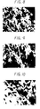
- Fig. 4 is a photograph of 1,000 magnifications
- Fig. 6 is a photograph of the inner surface of the hollow fiber shown in Fig. 4, observed by a microscope of 5,000 magnifications
- Fig. 7 is a photograph of the outer surface of the hollow fiber shown in Fig. 4, observed by a microscope of 10,000 magnifications
- Fig. 8 is a photograph of the inner surface area in the section of the hollow fiber shown in Fig. 4, observed by a microscope of 10,000 magnifications
- Fig. 9 is a photograph of the middle portion between the inner and outer surface areas in the section of the hollow fiber shown in Fig. 4, observed by a microscope of 10,000 magnifications
- Fig. 10 is a photograph showing the outer surface and the outer surface area in the section of the hollow fiber shown in Fig. 4, observed by a microscope of 10,000 magnifications;
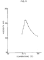
- Fig. 11 is a graph showing the relationship between the temperature and the viscosity of a spinning solution (13 % by weight solution of a polysulfone in a mixture of N-methyl-2-pyrrolidone and propylene glycol) as used in the preparation of the hollow fiber of the invention.
- Fig. 12 is a graph showing the relationship between the proportion of the propylene glycol non-solvent in a mixed solvent used for the preparation of a spinning solution and a transition temperature at which the viscosity of the spinning solution becomes maximum.
- the hollow fiber filter medium of the present invention is prepared from a polysulfone. Any of known polysulfone resins can be employed in the present invention, and aromatic polysulfone resins are preferable. Representative examples of the polysuflone resins used in the invention are a polysulfone having recurring units of the"general formula (I): and a polysulfone having recurring units of the general formula (II):
- the polysulfone (I) which has hitherto been used as a material of ultrafiltration membranes, is excellent in fundamental characteristics such as heat resistance, mechanical strength, chemical resistance and affinity for a living body, and accordingly is preferably used as a material for preparing the filter medium of the present invention.
- the filter medium of the present invention is in the form of a hollow fiber having a network structure or a sponge structure over the entire thickness from the inner surface to the outer surface.
- the maximum diameter of the pores of the porous hollow fiber is from 0.1 to 5 ⁇ m.
- the maximum diameter of the pore openings formed in the inner surface of the hollow fiber. is from 0.01 to 10 ⁇ m.
- the maximum diameter of the pore openings formed in the outer surface is from 0.01 to 5 ⁇ m.
- the filter medium of the invention has a water permeability of not less than 2.0 X 10 g./cm 2 .mmHg.min.
- maximum diameter means the length of the largest minor axis of the pores or openings of the hollow fiber observed by a microscope.
- Fig. 1 which is a micrograph of the section of the hollow fiber of the invention, shows that the hollow fiber has a uniform network or sponge structure and the maximum diameter of the pores is about 5 ⁇ m.
- Figs. 2 and 3 show that openings of the pores are present on the inner wall surface and the outer wall surface of the hollow fiber and the maximum diameters of the openings are about 0.04 ⁇ m. and about 0.3 ⁇ m., respectively.
- Figs. 4 and 5 which are micrographs of the section of another hollow fiber of the invention, show that the hollow fiber has a uniform network or sponge structure and the maximum diameter of the pores is about 1.5 ⁇ m.
- Figs. 1 which is a micrograph of the section of the hollow fiber of the invention, shows that the hollow fiber has a uniform network or sponge structure and the maximum diameter of the pores is about 5 ⁇ m.
- FIG. 6 and 7 show that openings of the pores are present on the inner wall surface and the outer wall surface of the hollow fiber and the maximum diameters of the openings are about 1 ⁇ m. and about 1.5 ⁇ m., respectively.
- Fig. 8 in which the portion near the inner wall surface in the section of the hollow fiber in Fig. 4 is enlarged, and Fig. 6 show the state that the network or sponge structure forms openings of indeterminate shape on the inner wall surface with a wide distribution of opening diameter.
- Fig. 10 in which the outer wall surface and the portion near the outer wall surface in the section of the hollow fiber shown in Fig. 4 are enlarged, shows the state that the network or sponge structure forms elliptic or circular openings on the outer wall surface.
- the filter medium of the present invention has the following feature.
- the hollow fiber filter medium of the present invention is greatly different from conventional polysulfone hollow fibers.
- the inner diameter and wall thickness of the hollow fiber filter medium of the invention are not technically limited to particular ranges. Usually, the inner diameter is selected from 100 ⁇ m. to 3 mm. and the wall thickness is selected from 20 to 500 ⁇ m. according to the purposes.
- the maximum diameters of the openings in the inner surface, the pores and the openings in the outer surface are from 0.01 to 10 ⁇ m., from 0.1 to 5 ⁇ m. and from 0.01 to 5 ⁇ m., respectively. It is preferable that the diameter of the pores is uniform over the entire thickness of the hollow fiber, but a certain distribution in pore diameter is permissible so far as the difference is not so large.
- a usual wet process for preparing a hollow fiber is applicable to the preparation of the hollow fiber filter medium of the present invention.
- the hollow fiber is prepared by extruding a spinning solution, namely a solution of a polysulfone in an organic solvent, from a slit of a ring nozzle together with an inside coagulating liquid which is sent forth from the inside portion of the nozzle, and immediately or after passing through a dry space of not more than 50 cm., preferably not more than 20 cm., from the nozzle, bringing the whole into contact with an outside coagulating liquid.
- the spinning solution of a polysulfone is prepared to have a transition temperature (Tc) at which the viscosity rise changes to the viscosity drop when the temperature of the spinning solution is dropped, and that the spinning solution formulated to have the transition temperature Tc and maintained at a temperature of not less than Tc is extruded from the ring nozzle to the outside coagulating liquid, while maintaining at least one of the inside coagulating liquid, the gas contacting the extrudate in the dry space of not more than 50 cm., preferably not more than 20 cm. and the outside coagulating liquid at a temperature of less than Tc, whereby a polysulfone hollow fiber having a network or sponge structure over the entire thickness extending from the inner surface to the outer surface of the hollow fiber is obtained.
- Tc transition temperature
- the spinning solution is prepared by dissolving a polysulfone in a specific solvent.
- a solvent having a relatively high boiling temperature Preferable solvents used for preparing the spinning solution are, for instance, dimethyl sulfoxide and mixed solvents of a major amount of one or more kinds of good solvents for polysulfone resins such as N-methyl-2-pyrrolidone, dimethylformamide and dimethylacetoamide and a minor amount of one or more kinds of non-solvents for polysulfone resins, which are used for adjusting the transition temperature Tc, e.g.
- the concentration of the polysulfone in the spinning solution is from 8 to 25 % by weight, preferably 10 to 17 % by weight. When the concentration is less than 8 % by weight, the viscosity of the spinning solution is low and the spinning operation is difficult. When the concentration is more than 25 % by weight, it is difficult to prepare a hollow fiber having large pores and openings.
- the transition temperature of the spinning solution is from 30° to 150 0 C., preferably 50° to 150°C.
- the transition temperature is less than 30 0 C., it is necessary to use a cooler to maintain at least one of the inside coagulating liquid, the outside coagulating liquid and the gas present in the dry space, below the transition temperature.
- the transition temperature is more than 150 0 C., the viscosity of the spinning solution becomes low because the spinning solution must be maintained at a high temperature, and accordingly the spinning is difficult.
- the transition temperature Tc has a close relation to the cloud point of the spinning solution, and is related to the phase separation due to the temperature drop of the spinning solution.
- Fig. 11 is a graph showing the relationship between the temperature and the viscosity of a solution, as used in the process of the present invention as a spinning solution, consisting of 13.0 % by weight of a polysulfone (commercially available under the commercial name "Udel Polysulfone P-3500" made by Union Carbide Corp.), 26.1 % by weight of propylene glycol and 60.9 % by weight of N-methyl-2-pyrrolidone (hereinafter referred to as "NMP").
- NMP N-methyl-2-pyrrolidone
- FIG. 12 is a graph showing the change in the transition temperature Tc with the change in the proportion of propylene glycol (PG) in a PG-NMP mixed solvent of the 13.0 % by weight polysulfone solution shown in Fig. 11.
- the transition temperature Tc can be controlled by changing the composition of a mixed solvent.
- the solvents used in the present invention serve as good solvents at temperatures of not less than Tc. Solutions of polysulfone having a composition such that the viscosity thereof suddenly drops with the temperature drop in the temperature range of less than Tc are suited for use in the process of the invention as spinning solutions.
- Non-solvents for the polysulfone having a miscibility with the solvents for the polysulfone and having an action of coagulating the polysulfone with contacting the spinning solution are used as inside coagulating liquids and outside coagulating liquids in the present invention.
- the coagulating liquids used in the invention are, for instance, water, mixtures of the above-mentioned good solvents for the polysulfone and water, and alcohols such as methanol, ethanol and isopropanol.
- a hollow fiber is formed by extruding the spinning solution maintained at a temperature of not less than the transition temperature Tc together with the inside coagulating liquid from a ring nozzle to a coagulation bath.
- the inner diameter and wall thickness of the hollow fiber of course vary depending on the size of the nozzle, the draft ratio and the inflation ratio. However, the draft ratio is within the range of about 0.8 to about 3 and the inflation ratio is within the range of about 0.4 to about 1.3, and accordingly they do not exert a large influence upon the structures of the inner surface, the network and the outer surface.
- the structures of the inner surface, the network and the outer surface can be properly adjusted by changing other spinning conditions such as the temperature of the inside coagulating liquid.
- the draft ratio and the inflation ratio are defined as follows: wherein d 1 is an outer diameter of the ring nozzle, d 2 is an inner diameter of the ring nozzle, q l is an amount of spinning solution sent forth, q 2 is an amount of inside coagulating liquid sent forth, and V is a rate of spinning.
- d 1 is an outer diameter of the ring nozzle
- d 2 is an inner diameter of the ring nozzle
- q l is an amount of spinning solution sent forth
- q 2 is an amount of inside coagulating liquid sent forth
- V is a rate of spinning.
- a ring nozzle is usually employed as a nozzle from which the spinning solution is sent forth.
- the spinning rate is determined according to the above-mentioned equations so as to satisfy the draft ratio and the inflation ratio with giving consideration to a relation to other factors. When the spinning rate is several tens of meters per minute, the operation is easy.
- the spinning solution is sent forth from the ring nozzle together with the inside coagulating liquid which is sent forth into the inside of the tubular extrudate, and immediately or after passing through a dry space of not more than about 50 cm., preferably not more than about 20 cm., they are brought into contact with the outside coagulating liquid. At that time, at least one of the inside coagulating liquid, the gas in the dry space and the outside coagulating liquid is maintained at a temperature of less than the transition temperature Tc of the spinning solution.
- the both temperatures of the inside and outside coagulating liquids may be not less than Tc and, in a preferable embodiment, the gas in the dry space is maintained at a temperature of less than Tc. More preferably, all of the inside and outside coagulating liquids and the gas are maintained at a temperature of less than Tc.
- the coagulation is substantially completed in the dry space. It is not necessary to use a specific gas as a gas in the dry space, and air is sufficient. Also, it is not particularly required to close the dry space, and the open state is sufficient. In general, the immersion time of several seconds in the outside coagulating liquid is sufficient.
- the difference between the transition temperature Tc of the spinning solution and the lowest temperature among the inside and outside coagulating liquids and the gas in the dry space is not less than 10°C., especially not less than 20°C.
- the spinning solution is suddenly coagulated by the extraction action and the cooling action of the coagulating liquids before the flocculation of polysulfone at the contacting surfaces with the coagulating liquids sufficiently develops, thus forming a porous hollow fiber having no skin or dense layer.
- concentration of the spinning solution is from about 10 to about 17 % by weight
- the porous hollow fibers of various grades having pores of about 0.01 to several micrometers in diameter can be easily prepared, for instance, merely by changing the temperature of the spinning solution.
- the coagulation owing to the coagulating liquids is usually caused by extraction of a solvent with the coagulating liquids from the extruded spinning solution.
- the coagulation of polysulfone is caused by simultaneous progress of the extraction of a solvent and cooling of the spinning solution to less than Tc. Therefore, from the viewpoint of the coagulation action owing to the above solvent extraction, both of the liquids having a rapid extraction action and the liquids having a mild extraction action can be employed in the present invention, unlike a conventional process.
- the surface contacting the coagulating liquid becomes a dense layer having pores of less than 0.01 ⁇ m.
- the conventional process produces a hollow fiber having a dense structure over the entire wall thickness, and the water permeability is very low. The reason is that the coagulation of the spinning solution is made only by extraction of the solvent in the conventional process.
- the hollow fiber immersed and coagulated in the outside coagulating liquid is subsequently immersed in water, etc. to remove the solvent remaining in the fiber, and if necessary, then dried.
- the drying is carried out preferably at a temperature of less than about 150°C. not causing the deformation of the produced hollow fiber.
- the hollow fiber filter medium of the present invention is prepared by a simple process, and has pores having a large diameter over the entire wall thickness extending from the inner surface to the outer surface, thus has a high water permeability, and moreover, is resistant against steam sterilization and excellent in mechanical strength, chemical resistance and affinity for value a living body. Accordingly, it is of a great practical as a filter for general use and a filter for medical use.
- the characteristics of the obtained hollow fibers are shown in Table 2, wherein Di(max) shows the largest minor axis (maximum diameter) of the openings present on the inner wall surface of a hollow fiber, Dn(max) shows the largest minor axis of the pores present in the sponge structure in section of the hollow fiber, and Do(max) shows the largest minor axis of the openigns present on the outer wall surface of the hollow fiber, and they are observed and measured by a microscope.
- a porous hollow fiber having an inner diameter 300 ⁇ m., an outer diameter 360 ⁇ m., a maximum diameter 0.4 ⁇ m. of openings on the inner surface, a maximum diameter 1 ⁇ m. of pores in the section and a maximum diameter 1 ⁇ m. of openings on the outer surface was prepared in the same manner as in Examples 1 to 10.
- a bundle of 150 hollow fibers was placed in a polycarbonate pipe having an inner diameter 9 mm., an outer diameter 13 mm. and a length 160 mm., and the both ends of the pipe was treated by potting to give a filter.
- the obtained filter was steam-sterilized at 120°C. for 30 minutes, and the bubble point and filtration performance to cow blood of the filter,were measured. Also, with respect to the non-steam-sterilized hollow fiber, the bubble point and filtration performance to cow blood were measured in the same manner.
Abstract
Description
- The present invention relates to a filter medium in the form of a hollow fiber, and more particularly to a hollow fiber filter medium having a large pore diameter made of a polysulfone resin and a process for the preparation thereof.
- Hollow fiber filter mediums have the advantages that a filter is made up in a small size with a simple structure and the flow of a fluid becomes uniform, since the effective membrane area per unit volume can be made large as compared with flat filter mediums. Therefore, in recent years, porous hollow fibers are being utilized as filter mediums in various fields in place of the flat filter mediums.
- Among the known hollow fiber filter mediums, hollow fibers made from resins such as polyvinyl alcohol, cellulose acetate, polymethyl methacrylate, polypropylene and polyethylene are known as hollow fiber filter mediums having a large pore diameter. The hollow fiber filter mediums made from these resins are not always satisfactory in points of the performance and preparation method thereof. For instance, they have the defects in performance that steam sterilization requiring high temperatures is impossible because of lack in heat resistance, the rate of filtration is low and the chemical resistance, mechanical strength or affinity for a living body is insufficient. Also, the methods for the preparation thereof have the defects that because of using high molecular weight compounds as pore-forming agents, a long time is required for removing them by extraction and it is also necessary therefor to use toxic solvents.
- A polysulfone resin is superior in heat resistance, mechanical resistance, chemical resistance and affinity for a living body. It has been utilized as a support for ultrafiltration membrane and reverse osmosis membrane, and many literatures therefor are also published. However, a polysulfone hollow fiber filter medium having a large pore diameter, at least having pores or openings of 0.01 to several micronmeters in diameter in the inner and outer surfaces, cannot be prepared by a conventional technique, and no polysulfone hollow fiber filter medium having pores or openings of not less than 0.01 µm. in diameter at least in the inner and outer surfaces has been provided up to now. For instance, processes for preparing polysulfone hollow fibers are reported in Japanese Unexamined Patent Publication (Tokkyo Kokai) No. 16378/1979, No. 143777/ 1979, No. 145379/1979, No. 152704/1981 and No. 82515/1982; and Journal of Applied Polymer Science, Vol. 20, 2377-2394(1976), Vol. 21, 165-180(1977) and Vol. 21, 1883-1900(1977). These publications disclose processes for preparing hollow fibers having the so-called asymmetric structure, that is, hollow fibers substantially having a thin, dense layer containing pores of less than 0.01 µm. in diameter in either one or both of the inner surface and the outer surface thereof. The amount of water permeation of these hollow fibers is small, even if the dense layer is made as thin as possible.
- It is an object of the present invention to provide a porous hollow fiber having a large pore diameter and useful as a filter medium.
- A further object of the invention is to provide a hollow fiber filter medium having a large pore diameter and excellent heat resistance, mechanical strength, chemical resistance and affinity for a living body.
- Another object of the invention is to provide a process for preparing a porous hollow fiber useful as a filter medium.
- These and other objects of the present invention will become apparent from the description hereinafter.
- In accordance with the present invention, there is provided a filter medium in the form of a porous hollow fiber made of a polysulfone having a network structure over the entire thickness from the inner surface to the outer surface, the pores having a maximum diameter of 0.1 to 5 µm., the openings of the pores formed in the inner surface having a maximum diameter of 0.01 to 10 µm. and the openings of the pores formed in the outer surface having a miximum diameter of 0.01 to 5 µm.
- The polysulfone hollow fiber filter medium of the present invention has excellent heat resistance, mechanical strength, chemical resistance and affinity for a living body. Aslo, since the pores formed by the network structure have a maximum diameter of 0.1 to 5 µm., the openings formed in the inner surface of the hollow fiber have a maximum diameter of 0.01 to 10 µm. and the openings formed in the outer surface of the hollow fiber have a maximum diameter of 0.01 to 5 µm., the hollow fiber filter medium of the invention has an excellent water permeability (filtration ability).
- Figs. 1 to 10 are microphotographs of the hollow fibers of the present invention, in which Fig. 1 is a photograph of the section of the hollow fiber of the invention observed by a microscope of 100 magnifications; Fig. 2 is a photograph of the inner surface of the hollow fiber shown in Fig. 1, observed by a microscope of 11,100 magnifications; Fig. 3 is a photograph of the outer surface of the hollow fiber shown in Fig. 1, observed by a microscope of 30,000 magnifications; Fig. 4 is a photograph of the section of another hollow fiber of the invention observed by a microscope of 100 magnifications; Fig. 5 is a photograph of the outer surface area in the sectional portion enclosed with the rectangle shown in Fig. 4, observed by a microscope of 1,000 magnifications; Fig. 6 is a photograph of the inner surface of the hollow fiber shown in Fig. 4, observed by a microscope of 5,000 magnifications; Fig. 7 is a photograph of the outer surface of the hollow fiber shown in Fig. 4, observed by a microscope of 10,000 magnifications; Fig. 8 is a photograph of the inner surface area in the section of the hollow fiber shown in Fig. 4, observed by a microscope of 10,000 magnifications; Fig. 9 is a photograph of the middle portion between the inner and outer surface areas in the section of the hollow fiber shown in Fig. 4, observed by a microscope of 10,000 magnifications; and Fig. 10 is a photograph showing the outer surface and the outer surface area in the section of the hollow fiber shown in Fig. 4, observed by a microscope of 10,000 magnifications;
- Fig. 11 is a graph showing the relationship between the temperature and the viscosity of a spinning solution (13 % by weight solution of a polysulfone in a mixture of N-methyl-2-pyrrolidone and propylene glycol) as used in the preparation of the hollow fiber of the invention; and
- Fig. 12 is a graph showing the relationship between the proportion of the propylene glycol non-solvent in a mixed solvent used for the preparation of a spinning solution and a transition temperature at which the viscosity of the spinning solution becomes maximum.
- The hollow fiber filter medium of the present invention is prepared from a polysulfone. Any of known polysulfone resins can be employed in the present invention, and aromatic polysulfone resins are preferable. Representative examples of the polysuflone resins used in the invention are a polysulfone having recurring units of the"general formula (I):


- The filter medium of the present invention is in the form of a hollow fiber having a network structure or a sponge structure over the entire thickness from the inner surface to the outer surface. The maximum diameter of the pores of the porous hollow fiber is from 0.1 to 5 µm., the maximum diameter of the pore openings formed in the inner surface of the hollow fiber.is from 0.01 to 10 µm., and the maximum diameter of the pore openings formed in the outer surface is from 0.01 to 5 µm. The filter medium of the invention has a water permeability of not less than 2.0 X 10 g./cm2.mmHg.min.
- The term "maximum diameter" as used herein means the length of the largest minor axis of the pores or openings of the hollow fiber observed by a microscope.
- The structure of the filter medium of the present invention will be explained with reference to the drawings. Fig. 1 which is a micrograph of the section of the hollow fiber of the invention, shows that the hollow fiber has a uniform network or sponge structure and the maximum diameter of the pores is about 5 µm. Figs. 2 and 3 show that openings of the pores are present on the inner wall surface and the outer wall surface of the hollow fiber and the maximum diameters of the openings are about 0.04 µm. and about 0.3 µm., respectively. Figs. 4 and 5 which are micrographs of the section of another hollow fiber of the invention, show that the hollow fiber has a uniform network or sponge structure and the maximum diameter of the pores is about 1.5 µm. Figs. 6 and 7 show that openings of the pores are present on the inner wall surface and the outer wall surface of the hollow fiber and the maximum diameters of the openings are about 1 µm. and about 1.5 µm., respectively. Fig. 8 in which the portion near the inner wall surface in the section of the hollow fiber in Fig. 4 is enlarged, and Fig. 6 show the state that the network or sponge structure forms openings of indeterminate shape on the inner wall surface with a wide distribution of opening diameter. Also, Fig. 10 in which the outer wall surface and the portion near the outer wall surface in the section of the hollow fiber shown in Fig. 4 are enlarged, shows the state that the network or sponge structure forms elliptic or circular openings on the outer wall surface.
- As is clear from the drawings and the explanation therefor, the filter medium of the present invention has the following feature.
- (1) The portion between the inner surface and the outer surface of the hollow fiber has a network or sponge structure.
- (2) A dense layer having only smaller pores than pores present in the sponge, namely a skin layer, is not present in the inner and outer surface areas of the hollow fiber.
- (3) The openings in the inner and outer surfaces of the hollow fiber are those formed by a part of the sponge broken outwardly.
- (4) The openings formed in the inner surface are in an indeterminate form and have a wide size distribution within the range of not more than the maximum diameter, and the rate of the area of openings in the inner surface is large.
- (5) The water permeability is large, and it is possible to obtain the filter medium having a water permeability of 2.0 X 10⁻³ to 40 X 10-3 g./cm2.mmHg.minute.
- (6) The openings formed in the outer surface are elliptic or circular.
- The above features indicate that the hollow fiber filter medium of the present invention is greatly different from conventional polysulfone hollow fibers.
- The inner diameter and wall thickness of the hollow fiber filter medium of the invention are not technically limited to particular ranges. Usually, the inner diameter is selected from 100 µm. to 3 mm. and the wall thickness is selected from 20 to 500 µm. according to the purposes.
- When either one of the maximum diameters of the openings on the inner surface and the openings on the outer surface is less than 0.01 µm., the amount of water permeated is smaller than that of a conventional ultrafiltration membrane, and accordingly one of the advantages of the invention, namely a good water permeability, is lost. Of course, another feature of the invention that relatively large particles can permeate through the filter medium is also lost. On the other hand, when the maximum diameters of all of the pores in the sponge body and the openings in the inner and outer surfaces exceed 5 µm., 10 µm. and 5 µm., respectively, the mechanical strength of the hollow fiber is lowered. Accordingly, it is preferable in practical use that the maximum diameters of the openings in the inner surface, the pores and the openings in the outer surface are from 0.01 to 10 µm., from 0.1 to 5 µm. and from 0.01 to 5 µm., respectively. It is preferable that the diameter of the pores is uniform over the entire thickness of the hollow fiber, but a certain distribution in pore diameter is permissible so far as the difference is not so large.
- A usual wet process for preparing a hollow fiber is applicable to the preparation of the hollow fiber filter medium of the present invention. For instance, the hollow fiber is prepared by extruding a spinning solution, namely a solution of a polysulfone in an organic solvent, from a slit of a ring nozzle together with an inside coagulating liquid which is sent forth from the inside portion of the nozzle, and immediately or after passing through a dry space of not more than 50 cm., preferably not more than 20 cm., from the nozzle, bringing the whole into contact with an outside coagulating liquid. In the present invention, it is essential that the spinning solution of a polysulfone is prepared to have a transition temperature (Tc) at which the viscosity rise changes to the viscosity drop when the temperature of the spinning solution is dropped, and that the spinning solution formulated to have the transition temperature Tc and maintained at a temperature of not less than Tc is extruded from the ring nozzle to the outside coagulating liquid, while maintaining at least one of the inside coagulating liquid, the gas contacting the extrudate in the dry space of not more than 50 cm., preferably not more than 20 cm. and the outside coagulating liquid at a temperature of less than Tc, whereby a polysulfone hollow fiber having a network or sponge structure over the entire thickness extending from the inner surface to the outer surface of the hollow fiber is obtained.
- The spinning solution is prepared by dissolving a polysulfone in a specific solvent. For obtaining the spinning solution having a desired transition temperature Tc, it is desirable to use a solvent having a relatively high boiling temperature. Preferable solvents used for preparing the spinning solution are, for instance, dimethyl sulfoxide and mixed solvents of a major amount of one or more kinds of good solvents for polysulfone resins such as N-methyl-2-pyrrolidone, dimethylformamide and dimethylacetoamide and a minor amount of one or more kinds of non-solvents for polysulfone resins, which are used for adjusting the transition temperature Tc, e.g. polyhydric alcohols such as glycerol, propylene glycol, ethylene glycol and butanediol and alcohols having a high boiling temperature such as cyclohexanol. The use of the mixed solvents is preferred, since the spinning solution having a desired transition temperature is obtained. The concentration of the polysulfone in the spinning solution is from 8 to 25 % by weight, preferably 10 to 17 % by weight. When the concentration is less than 8 % by weight, the viscosity of the spinning solution is low and the spinning operation is difficult. When the concentration is more than 25 % by weight, it is difficult to prepare a hollow fiber having large pores and openings.
- The transition temperature of the spinning solution is from 30° to 1500C., preferably 50° to 150°C. When the transition temperature is less than 300C., it is necessary to use a cooler to maintain at least one of the inside coagulating liquid, the outside coagulating liquid and the gas present in the dry space, below the transition temperature. When the transition temperature is more than 1500C., the viscosity of the spinning solution becomes low because the spinning solution must be maintained at a high temperature, and accordingly the spinning is difficult.
- In many cases, the transition temperature Tc has a close relation to the cloud point of the spinning solution, and is related to the phase separation due to the temperature drop of the spinning solution. Fig. 11 is a graph showing the relationship between the temperature and the viscosity of a solution, as used in the process of the present invention as a spinning solution, consisting of 13.0 % by weight of a polysulfone (commercially available under the commercial name "Udel Polysulfone P-3500" made by Union Carbide Corp.), 26.1 % by weight of propylene glycol and 60.9 % by weight of N-methyl-2-pyrrolidone (hereinafter referred to as "NMP"). Fig. 12 is a graph showing the change in the transition temperature Tc with the change in the proportion of propylene glycol (PG) in a PG-NMP mixed solvent of the 13.0 % by weight polysulfone solution shown in Fig. 11. As shown in Fig. 12, the transition temperature Tc can be controlled by changing the composition of a mixed solvent. The solvents used in the present invention serve as good solvents at temperatures of not less than Tc. Solutions of polysulfone having a composition such that the viscosity thereof suddenly drops with the temperature drop in the temperature range of less than Tc are suited for use in the process of the invention as spinning solutions.
- Non-solvents for the polysulfone having a miscibility with the solvents for the polysulfone and having an action of coagulating the polysulfone with contacting the spinning solution are used as inside coagulating liquids and outside coagulating liquids in the present invention. Examples of the coagulating liquids used in the invention are, for instance, water, mixtures of the above-mentioned good solvents for the polysulfone and water, and alcohols such as methanol, ethanol and isopropanol.
- In the present invention, a hollow fiber is formed by extruding the spinning solution maintained at a temperature of not less than the transition temperature Tc together with the inside coagulating liquid from a ring nozzle to a coagulation bath. The inner diameter and wall thickness of the hollow fiber of course vary depending on the size of the nozzle, the draft ratio and the inflation ratio. However, the draft ratio is within the range of about 0.8 to about 3 and the inflation ratio is within the range of about 0.4 to about 1.3, and accordingly they do not exert a large influence upon the structures of the inner surface, the network and the outer surface. The structures of the inner surface, the network and the outer surface can be properly adjusted by changing other spinning conditions such as the temperature of the inside coagulating liquid. The draft ratio and the inflation ratio are defined as follows:


- The spinning solution is sent forth from the ring nozzle together with the inside coagulating liquid which is sent forth into the inside of the tubular extrudate, and immediately or after passing through a dry space of not more than about 50 cm., preferably not more than about 20 cm., they are brought into contact with the outside coagulating liquid. At that time, at least one of the inside coagulating liquid, the gas in the dry space and the outside coagulating liquid is maintained at a temperature of less than the transition temperature Tc of the spinning solution. When the length of the dry space, in other words, the distance between the nozzle tip and the outside coagulating liquid, is less than several centimeters, it is preferable to maintain the both of the inside and outside coagulating liquids at a temperature of less than Tc, since it is difficult to proceed with the coagulation in the dry space. When the dry space is more than several centimeters, it is relatively easy to proceed with the coagulation in the dry space and, therefore, the both temperatures of the inside and outside coagulating liquids may be not less than Tc and, in a preferable embodiment, the gas in the dry space is maintained at a temperature of less than Tc. More preferably, all of the inside and outside coagulating liquids and the gas are maintained at a temperature of less than Tc. Also, preferably, the coagulation is substantially completed in the dry space. It is not necessary to use a specific gas as a gas in the dry space, and air is sufficient. Also, it is not particularly required to close the dry space, and the open state is sufficient. In general, the immersion time of several seconds in the outside coagulating liquid is sufficient.
- It is preferable that the difference between the transition temperature Tc of the spinning solution and the lowest temperature among the inside and outside coagulating liquids and the gas in the dry space is not less than 10°C., especially not less than 20°C.
- When the spinning conditions are adequately set as mentioned above, the spinning solution is suddenly coagulated by the extraction action and the cooling action of the coagulating liquids before the flocculation of polysulfone at the contacting surfaces with the coagulating liquids sufficiently develops, thus forming a porous hollow fiber having no skin or dense layer. Also, when the concentration of the spinning solution is from about 10 to about 17 % by weight, the porous hollow fibers of various grades having pores of about 0.01 to several micrometers in diameter can be easily prepared, for instance, merely by changing the temperature of the spinning solution.
- The coagulation owing to the coagulating liquids is usually caused by extraction of a solvent with the coagulating liquids from the extruded spinning solution. On the other hand, in the process of the invention, the coagulation of polysulfone is caused by simultaneous progress of the extraction of a solvent and cooling of the spinning solution to less than Tc. Therefore, from the viewpoint of the coagulation action owing to the above solvent extraction, both of the liquids having a rapid extraction action and the liquids having a mild extraction action can be employed in the present invention, unlike a conventional process. In a conventional process, in case of using a coagulating liquid having the coagulating action owing to rapid solvent extraction, the surface contacting the coagulating liquid becomes a dense layer having pores of less than 0.01 µm. in diameter. Also, a relatively uniform sponge structure is not formed, but the section of the hollow fiber has the so-called asymmetric structure in which the pores increasingly become large toward the inside from the surface. In case of using a coagulating liquid having the coagulating action owing to mild solvent extraction, the conventional process produces a hollow fiber having a dense structure over the entire wall thickness, and the water permeability is very low. The reason is that the coagulation of the spinning solution is made only by extraction of the solvent in the conventional process.
- The hollow fiber immersed and coagulated in the outside coagulating liquid is subsequently immersed in water, etc. to remove the solvent remaining in the fiber, and if necessary, then dried. The drying is carried out preferably at a temperature of less than about 150°C. not causing the deformation of the produced hollow fiber.
- The hollow fiber filter medium of the present invention is prepared by a simple process, and has pores having a large diameter over the entire wall thickness extending from the inner surface to the outer surface, thus has a high water permeability, and moreover, is resistant against steam sterilization and excellent in mechanical strength, chemical resistance and affinity for value a living body. Accordingly, it is of a great practical as a filter for general use and a filter for medical use.
- The present invention is more specifically described and explained by means of the following Examples, in which all % and parts are by weight unless otherwise noted. It is to be understood that the present invention is not limited to the Examples, and various changes and modifications may be made in the invention without departing from the spirit and scope thereof.
- In 87 parts of a mixed solvent consisting of 29.5 % of propylene glycol and 70.5 % of N-methyl-2-pyrrolidone (NMP) was dissolved 13 parts of a polysulfone (commercially available under the commercial name "Udel Polysuphone P-3500" made by Union Carbide Corp.) at 110°C. for 3 hours with agitation. The resulting solution was defoamed under reduced pressure to give a spinning solution A. The spinning solution A had a transition temperature of 73°C. The spinning was carried out by extruding the spinning solution A from a ring nozzle having an inner diameter of 400 um. and an outer diameter of 600 µm. at a rate of 3.4 g./minute into an outside coagulating liquid under the conditions shown in Table 1, while extruding an inside coagulating liquid maintained at a prescribed temperature at a rate of 2.5 ml./minute from the inside of the ring nozzle.
- The characteristics of the obtained hollow fibers are shown in Table 2, wherein Di(max) shows the largest minor axis (maximum diameter) of the openings present on the inner wall surface of a hollow fiber, Dn(max) shows the largest minor axis of the pores present in the sponge structure in section of the hollow fiber, and Do(max) shows the largest minor axis of the openigns present on the outer wall surface of the hollow fiber, and they are observed and measured by a microscope.
- In 87 parts of a mixed solvent consisting of 28.7 % of propylene glycol and 71.3 % of NMP was dissolved 13 parts of the same polysulfone as used in Examples 1 to 10 at 110oc. for 3 hours with agitation. The resulting solution was defoamed under reduced pressure to give a spinning solution B having a transition temperature of 56°C. The spinning was carried out by extruding the spinning solution B from a ring nozzle having an inner diameter of 350 µm. and an outer diameter of 550 µm. at a rate of 3.2 g./minute into an outside coagulating liquid under the conditions shown in Table 1, while extruding an inside coagulating liquid maintained at a prescribed temperature at a rate of 1.8 ml./minute.
- The characteristics of the obtained hollow fibers are shown in Table 2.


- A porous hollow fiber having an inner diameter 300 µm., an outer diameter 360 µm., a maximum diameter 0.4 µm. of openings on the inner surface, a maximum diameter 1 µm. of pores in the section and a maximum diameter 1 µm. of openings on the outer surface was prepared in the same manner as in Examples 1 to 10. A bundle of 150 hollow fibers was placed in a polycarbonate pipe having an inner diameter 9 mm., an outer diameter 13 mm. and a length 160 mm., and the both ends of the pipe was treated by potting to give a filter.
- The obtained filter was steam-sterilized at 120°C. for 30 minutes, and the bubble point and filtration performance to cow blood of the filter,were measured. Also, with respect to the non-steam-sterilized hollow fiber, the bubble point and filtration performance to cow blood were measured in the same manner.
- No change between the sterilized filter and the nonsterilized filter was observed, thus it was confirmed that the filter medium of the invention is proof against steam sterilization at high temperatures. Also, the appearance of the filter was not changed by steam sterilization.
Claims (4)
Applications Claiming Priority (2)
| Application Number | Priority Date | Filing Date | Title |
|---|---|---|---|
| JP58062835A JPS59189903A (en) | 1983-04-09 | 1983-04-09 | Hollow yarn like filter and preparation thereof |
| JP62835/83 | 1983-04-09 |
Publications (3)
| Publication Number | Publication Date |
|---|---|
| EP0121911A2 true EP0121911A2 (en) | 1984-10-17 |
| EP0121911A3 EP0121911A3 (en) | 1985-07-31 |
| EP0121911B1 EP0121911B1 (en) | 1988-10-19 |
Family
ID=13211764
Family Applications (1)
| Application Number | Title | Priority Date | Filing Date |
|---|---|---|---|
| EP84103807A Expired EP0121911B1 (en) | 1983-04-09 | 1984-04-06 | Hollow fiber filter medium and process for preparing the same |
Country Status (6)
| Country | Link |
|---|---|
| US (1) | US4612119A (en) |
| EP (1) | EP0121911B1 (en) |
| JP (1) | JPS59189903A (en) |
| AU (1) | AU558499B2 (en) |
| CA (1) | CA1237859A (en) |
| DE (1) | DE3474637D1 (en) |
Cited By (10)
| Publication number | Priority date | Publication date | Assignee | Title |
|---|---|---|---|---|
| EP0341473A2 (en) | 1988-04-30 | 1989-11-15 | Akzo Nobel N.V. | Process for sulphonating aromatic polyether sulphones, and the sulphonated polyether sulphones |
| US4976859A (en) * | 1988-09-01 | 1990-12-11 | Akzo N.V. | Integral asymmetric polyether-sulfone membrane, process for its production, and use for ultrafiltration and microfiltration |
| EP0543355A2 (en) * | 1991-11-19 | 1993-05-26 | Kanegafuchi Kagaku Kogyo Kabushiki Kaisha | Polysulfone porous hollow fiber |
| EP0572274A2 (en) * | 1992-05-29 | 1993-12-01 | W.R. Grace & Co.-Conn. | Novel high flux hollow fiber membrane |
| WO1998029478A1 (en) * | 1996-12-31 | 1998-07-09 | Althin Medical, Inc. | Melt-spun polysulfone semipermeable membranes and methods for making the same |
| US6218441B1 (en) | 1997-09-18 | 2001-04-17 | Timothy B. Meluch | Melt-spun polysulfone semipermeable membranes and methods for making the same |
| US7144505B2 (en) | 1997-09-18 | 2006-12-05 | Baxter International Inc. | Melt-spun polysulfone semipermeable membranes and methods for making the same |
| WO2008118580A1 (en) * | 2007-03-28 | 2008-10-02 | 3M Innovative Properties Company | Process for forming microporous membranes |
| WO2014084705A1 (en) * | 2012-11-30 | 2014-06-05 | Instituto Tecnológico y de Estudios Superiores de Monterrey | Method for obtaining porous hollow fibres having molecularly imprinted spheres embedded therein and modular device formed by the resulting fibres |
| CN106360843A (en) * | 2016-09-22 | 2017-02-01 | 东华大学 | High-comfortableness nano fiber self-adhesion protective mask |
Families Citing this family (29)
| Publication number | Priority date | Publication date | Assignee | Title |
|---|---|---|---|---|
| JPS5836951A (en) * | 1981-08-24 | 1983-03-04 | Ushio Inc | Structure body for airtight sealing of metal and glass |
| JPS60222112A (en) * | 1984-04-20 | 1985-11-06 | Kanegafuchi Chem Ind Co Ltd | Hollow yarn-shaped filter and its manufacture |
| JPS61232860A (en) * | 1985-04-08 | 1986-10-17 | 鐘淵化学工業株式会社 | Polysulfone hollow yarn for separating serum |
| ES2052605T3 (en) * | 1986-08-15 | 1994-07-16 | Permea Inc | ASYMMETRIC GAS SEPARATION MEMBRANES THAT HAVE FILMS OF GRADUATED DENSITY. |
| US4728346A (en) * | 1986-08-15 | 1988-03-01 | Permea Inc. | Permeation modified asymmetric gas separation membranes having graded density skins |
| JPS6391102A (en) * | 1986-10-03 | 1988-04-21 | Kanegafuchi Chem Ind Co Ltd | Membrane for separating blood plasma component |
| US4990252A (en) * | 1987-02-04 | 1991-02-05 | Hydanautics | Stable membranes from sulfonated polyarylethers |
| WO1989004206A1 (en) * | 1987-11-06 | 1989-05-18 | The Dow Chemical Company | Semi-permeable membranes with an internal discriminating region |
| US4838904A (en) * | 1987-12-07 | 1989-06-13 | The Dow Chemical Company | Semi-permeable membranes with an internal discriminating region |
| US4970034A (en) * | 1988-09-23 | 1990-11-13 | W. R. Grace & Co.-Conn. | Process for preparing isotropic microporous polysulfone membranes |
| US5049276A (en) * | 1988-10-13 | 1991-09-17 | Fuji Photo Film Co., Ltd. | Hollow fiber membrane |
| US5683916A (en) * | 1988-10-31 | 1997-11-04 | Hemasure Inc. | Membrane affinity apparatus and purification methods related thereto |
| FR2641709B1 (en) * | 1988-12-22 | 1992-01-17 | Lyonnaise Eaux | PROCESS FOR THE MANUFACTURE OF AN ORGANIC POROUS MATERIAL, ESPECIALLY AN ORGANIC SEMI-PERMEABLE MEMBRANE, COMPRISING A PLURALITY OF SEPARATE LONGITUDINAL CHANNELS |
| FR2641708B1 (en) * | 1988-12-22 | 1992-01-17 | Lyonnaise Eaux | PROCESS FOR THE MANUFACTURE OF AN ORGANIC POROUS MATERIAL, ESPECIALLY AN ORGANIC SEMI-PERMEABLE MEMBRANE, COMPRISING A PLURALITY OF SEPARATE LONGITUDINAL CHANNELS |
| US4992221A (en) * | 1989-09-27 | 1991-02-12 | Permea, Inc. | Asymmetric gas separation membranes having improved strength |
| US5013767A (en) * | 1989-09-27 | 1991-05-07 | Permea, Inc. | Asymmetric gas separation membranes having improved strength |
| US5227063A (en) * | 1989-10-03 | 1993-07-13 | Zenon Environmental Inc. | Tubular membrane module |
| US5102917A (en) * | 1990-09-14 | 1992-04-07 | Cpc Engineering Corporation | Porous polysulfone media suitable for filtration |
| US5096585A (en) * | 1991-01-28 | 1992-03-17 | W. R. Grace & Co.-Conn. | Process for preparing protein non-adsorptive microporous polysulfone membranes |
| US5151227A (en) * | 1991-03-18 | 1992-09-29 | W. R. Grace & Co.-Conn. | Process for continuous spinning of hollow-fiber membranes using a solvent mixture as a precipitation medium |
| EP0882494B1 (en) * | 1995-12-18 | 2002-03-20 | Asahi Kasei Kabushiki Kaisha | Hollow fiber type filtration membrane |
| US6074718A (en) * | 1996-02-06 | 2000-06-13 | Koch Membrane Systems, Inc. | Self supporting hollow fiber membrane and method of construction |
| US5693694A (en) * | 1996-03-20 | 1997-12-02 | W.R. Grace & Co.-Conn. | Low and medium flux membranes |
| US6612447B1 (en) * | 2000-07-24 | 2003-09-02 | Baxter International Inc. | Blood collection systems and filters using a porous membrane element |
| US6890435B2 (en) * | 2002-01-28 | 2005-05-10 | Koch Membrane Systems | Hollow fiber microfiltration membranes and a method of making these membranes |
| TWI377978B (en) * | 2008-05-21 | 2012-12-01 | Mitsubishi Rayon Co | Hollow porous film and manufacturing method thereof |
| JP5578210B2 (en) * | 2012-08-27 | 2014-08-27 | 東洋紡株式会社 | Method for producing porous hollow fiber membrane |
| US10851241B2 (en) | 2014-11-19 | 2020-12-01 | Cytiva Sweden Ab | Zwitterion-functionalized multicomponent copolymers and associated polymer blends and membranes |
| JP7026344B2 (en) * | 2017-07-25 | 2022-02-28 | 株式会社ダイセル | Membrane-forming solution and method for manufacturing a separation membrane using it |
Citations (6)
| Publication number | Priority date | Publication date | Assignee | Title |
|---|---|---|---|---|
| GB2000720A (en) * | 1977-07-08 | 1979-01-17 | Asahi Chemical Ind | Semipermeable membranes of polyaryl ether sulphones |
| FR2424750A1 (en) * | 1978-05-02 | 1979-11-30 | Asahi Chemical Ind | SEMI-PERMEABLE MEMBRANE IN POLYARYL ETHER SULFONE AND PRODUCTION PROCESS |
| GB2047162A (en) * | 1979-03-28 | 1980-11-26 | Monsanto Co | Anisotropic membranes |
| EP0036315A2 (en) * | 1980-03-14 | 1981-09-23 | Memtec America Corporation | Anisotropic membranes |
| EP0092587A1 (en) * | 1981-10-30 | 1983-11-02 | Toray Industries, Inc. | Polymethyl methacrylate hollow yarn ultra-filtration membrane and process for its production |
| JPS5958041A (en) * | 1982-09-28 | 1984-04-03 | Teijin Ltd | Preparation of porous polysulfone membrane |
Family Cites Families (2)
| Publication number | Priority date | Publication date | Assignee | Title |
|---|---|---|---|---|
| JPS53106137A (en) * | 1977-02-28 | 1978-09-14 | Ricoh Co Ltd | Detection of tone concentration |
| JPS55148210A (en) * | 1979-04-30 | 1980-11-18 | Kuraray Co Ltd | Preparation of hollow ethylene-vinyl alcohol membrane |
-
1983
- 1983-04-09 JP JP58062835A patent/JPS59189903A/en active Pending
-
1984
- 1984-04-05 CA CA000451385A patent/CA1237859A/en not_active Expired
- 1984-04-06 DE DE8484103807T patent/DE3474637D1/en not_active Expired
- 1984-04-06 EP EP84103807A patent/EP0121911B1/en not_active Expired
- 1984-04-09 US US06/597,890 patent/US4612119A/en not_active Expired - Lifetime
- 1984-04-09 AU AU26646/84A patent/AU558499B2/en not_active Expired
Patent Citations (6)
| Publication number | Priority date | Publication date | Assignee | Title |
|---|---|---|---|---|
| GB2000720A (en) * | 1977-07-08 | 1979-01-17 | Asahi Chemical Ind | Semipermeable membranes of polyaryl ether sulphones |
| FR2424750A1 (en) * | 1978-05-02 | 1979-11-30 | Asahi Chemical Ind | SEMI-PERMEABLE MEMBRANE IN POLYARYL ETHER SULFONE AND PRODUCTION PROCESS |
| GB2047162A (en) * | 1979-03-28 | 1980-11-26 | Monsanto Co | Anisotropic membranes |
| EP0036315A2 (en) * | 1980-03-14 | 1981-09-23 | Memtec America Corporation | Anisotropic membranes |
| EP0092587A1 (en) * | 1981-10-30 | 1983-11-02 | Toray Industries, Inc. | Polymethyl methacrylate hollow yarn ultra-filtration membrane and process for its production |
| JPS5958041A (en) * | 1982-09-28 | 1984-04-03 | Teijin Ltd | Preparation of porous polysulfone membrane |
Non-Patent Citations (2)
| Title |
|---|
| JOURNAL OF APPLIED POLYMER SCIENCE, vol. 21, 1977, pages 165-180, John Wiley & Sons Inc., New York, US; I. CABASSO et al.: "Polysulfone hollow fibers. II. Morphology" * |
| PATENTS ABSTRACTS OF JAPAN, vol. 8, no. 156 (C-234)[1593], 19th July 1984; & JP - A - 59 58 041 (TEIJIN K.K.) 03-04-1984 * |
Cited By (20)
| Publication number | Priority date | Publication date | Assignee | Title |
|---|---|---|---|---|
| EP0341473A2 (en) | 1988-04-30 | 1989-11-15 | Akzo Nobel N.V. | Process for sulphonating aromatic polyether sulphones, and the sulphonated polyether sulphones |
| US5013765A (en) * | 1988-04-30 | 1991-05-07 | Akzo N.V. | Method for sulfonating aromatic polyether sulfones |
| US4976859A (en) * | 1988-09-01 | 1990-12-11 | Akzo N.V. | Integral asymmetric polyether-sulfone membrane, process for its production, and use for ultrafiltration and microfiltration |
| EP0543355A2 (en) * | 1991-11-19 | 1993-05-26 | Kanegafuchi Kagaku Kogyo Kabushiki Kaisha | Polysulfone porous hollow fiber |
| EP0543355A3 (en) * | 1991-11-19 | 1993-09-22 | Kanegafuchi Kagaku Kogyo Kabushiki Kaisha | Polysulfone porous hollow fiber |
| US5474680A (en) * | 1991-11-19 | 1995-12-12 | Kanegafuchi Kagaku Kogyo Kabushiki Kaisha | Polysulfone porous hollow fiber |
| EP0779381A2 (en) | 1991-11-19 | 1997-06-18 | Kanegafuchi Kagaku Kogyo Kabushiki Kaisha | Polysulfone porous hollow fiber |
| EP0779381A3 (en) * | 1991-11-19 | 1998-04-08 | Kanegafuchi Kagaku Kogyo Kabushiki Kaisha | Polysulfone porous hollow fiber |
| EP0572274A2 (en) * | 1992-05-29 | 1993-12-01 | W.R. Grace & Co.-Conn. | Novel high flux hollow fiber membrane |
| EP0572274A3 (en) * | 1992-05-29 | 1994-05-18 | Grace W R & Co | Novel high flux hollow fiber membrane |
| WO1998029478A1 (en) * | 1996-12-31 | 1998-07-09 | Althin Medical, Inc. | Melt-spun polysulfone semipermeable membranes and methods for making the same |
| US6218441B1 (en) | 1997-09-18 | 2001-04-17 | Timothy B. Meluch | Melt-spun polysulfone semipermeable membranes and methods for making the same |
| US6881337B2 (en) | 1997-09-18 | 2005-04-19 | Baxter International Inc. | Melt-spun polysulfone semipermeable membranes and methods for making the same |
| US7144505B2 (en) | 1997-09-18 | 2006-12-05 | Baxter International Inc. | Melt-spun polysulfone semipermeable membranes and methods for making the same |
| WO2008118580A1 (en) * | 2007-03-28 | 2008-10-02 | 3M Innovative Properties Company | Process for forming microporous membranes |
| US7842214B2 (en) | 2007-03-28 | 2010-11-30 | 3M Innovative Properties Company | Process for forming microporous membranes |
| KR101461693B1 (en) * | 2007-03-28 | 2014-11-13 | 쓰리엠 이노베이티브 프로퍼티즈 컴파니 | Process for forming microporous membranes |
| WO2014084705A1 (en) * | 2012-11-30 | 2014-06-05 | Instituto Tecnológico y de Estudios Superiores de Monterrey | Method for obtaining porous hollow fibres having molecularly imprinted spheres embedded therein and modular device formed by the resulting fibres |
| CN106360843A (en) * | 2016-09-22 | 2017-02-01 | 东华大学 | High-comfortableness nano fiber self-adhesion protective mask |
| CN106360843B (en) * | 2016-09-22 | 2017-10-31 | 东华大学 | A kind of high-comfort nanofiber self-adhesion protective mask |
Also Published As
| Publication number | Publication date |
|---|---|
| AU558499B2 (en) | 1987-01-29 |
| EP0121911A3 (en) | 1985-07-31 |
| AU2664684A (en) | 1984-10-11 |
| US4612119A (en) | 1986-09-16 |
| JPS59189903A (en) | 1984-10-27 |
| DE3474637D1 (en) | 1988-11-24 |
| EP0121911B1 (en) | 1988-10-19 |
| CA1237859A (en) | 1988-06-14 |
Similar Documents
| Publication | Publication Date | Title |
|---|---|---|
| EP0121911B1 (en) | Hollow fiber filter medium and process for preparing the same | |
| JP5433921B2 (en) | Polymer porous hollow fiber membrane | |
| US4812269A (en) | Process for producing hollow fiber semi-permeable membranes | |
| KR20050090373A (en) | Membrane and use thereof | |
| JPS6356802B2 (en) | ||
| US20050242021A1 (en) | Hollow fibres | |
| JPS61164602A (en) | Hllow yarn membrane made of polysulfone resin and its preparation | |
| JPH07289863A (en) | Polysulfone hollow fiber membrane and its production | |
| JPS61200806A (en) | Polyether sulfone porous hollow yarn membrane and its production | |
| JPH03258330A (en) | Porous hollow fiber membrane | |
| JPH053335B2 (en) | ||
| JPS6336805B2 (en) | ||
| JP2688564B2 (en) | Cellulose acetate hollow fiber separation membrane | |
| JPH09308685A (en) | Hollow fiber membrane for blood purification and blood purifying device | |
| JPWO2016182015A1 (en) | Porous hollow fiber membrane and method for producing the same | |
| JPS61200805A (en) | Polyether sulfone microporous hollow yarn membrane and its production | |
| JPS59228016A (en) | Hollow yarn membrane of aromatic polysulfone | |
| JP2004098027A (en) | High-performance precision filtration film | |
| JPH03174233A (en) | Production of aromatic polysulfone hollow-fiber membrane | |
| JP2005058906A (en) | Porous polymer membrane, blood purification device and production method for porous polymer membrane | |
| JP3464000B1 (en) | Manufacturing method of high performance hollow fiber microfiltration membrane | |
| JPH0952030A (en) | Polyvinyl alcohol hollow yarn membrane and its manufacture | |
| JPH09253463A (en) | Manufacture of polysulfone type ultrafiltration film | |
| JP2000107577A (en) | Production of permselective hollow fiber membranes | |
| JPH0420651B2 (en) |
Legal Events
| Date | Code | Title | Description |
|---|---|---|---|
| PUAI | Public reference made under article 153(3) epc to a published international application that has entered the european phase |
Free format text: ORIGINAL CODE: 0009012 |
|
| AK | Designated contracting states |
Designated state(s): BE DE FR GB IT NL SE |
|
| 17P | Request for examination filed |
Effective date: 19850313 |
|
| PUAL | Search report despatched |
Free format text: ORIGINAL CODE: 0009013 |
|
| AK | Designated contracting states |
Designated state(s): BE DE FR GB IT NL SE |
|
| 17Q | First examination report despatched |
Effective date: 19860430 |
|
| D17Q | First examination report despatched (deleted) | ||
| GRAA | (expected) grant |
Free format text: ORIGINAL CODE: 0009210 |
|
| AK | Designated contracting states |
Kind code of ref document: B1 Designated state(s): BE DE FR GB IT NL SE |
|
| ITF | It: translation for a ep patent filed |
Owner name: STUDIO CONS. BREVETTUALE S.R.L. |
|
| REF | Corresponds to: |
Ref document number: 3474637 Country of ref document: DE Date of ref document: 19881124 |
|
| ET | Fr: translation filed | ||
| PLBE | No opposition filed within time limit |
Free format text: ORIGINAL CODE: 0009261 |
|
| STAA | Information on the status of an ep patent application or granted ep patent |
Free format text: STATUS: NO OPPOSITION FILED WITHIN TIME LIMIT |
|
| 26N | No opposition filed | ||
| ITTA | It: last paid annual fee | ||
| EAL | Se: european patent in force in sweden |
Ref document number: 84103807.8 |
|
| REG | Reference to a national code |
Ref country code: GB Ref legal event code: IF02 |
|
| PGFP | Annual fee paid to national office [announced via postgrant information from national office to epo] |
Ref country code: GB Payment date: 20030402 Year of fee payment: 20 |
|
| PGFP | Annual fee paid to national office [announced via postgrant information from national office to epo] |
Ref country code: SE Payment date: 20030404 Year of fee payment: 20 |
|
| PGFP | Annual fee paid to national office [announced via postgrant information from national office to epo] |
Ref country code: FR Payment date: 20030408 Year of fee payment: 20 |
|
| PGFP | Annual fee paid to national office [announced via postgrant information from national office to epo] |
Ref country code: DE Payment date: 20030417 Year of fee payment: 20 |
|
| PGFP | Annual fee paid to national office [announced via postgrant information from national office to epo] |
Ref country code: NL Payment date: 20030429 Year of fee payment: 20 |
|
| PGFP | Annual fee paid to national office [announced via postgrant information from national office to epo] |
Ref country code: BE Payment date: 20030617 Year of fee payment: 20 |
|
| PG25 | Lapsed in a contracting state [announced via postgrant information from national office to epo] |
Ref country code: GB Free format text: LAPSE BECAUSE OF EXPIRATION OF PROTECTION Effective date: 20040405 |
|
| PG25 | Lapsed in a contracting state [announced via postgrant information from national office to epo] |
Ref country code: NL Free format text: LAPSE BECAUSE OF EXPIRATION OF PROTECTION Effective date: 20040406 |
|
| REG | Reference to a national code |
Ref country code: GB Ref legal event code: PE20 |
|
| BE20 | Be: patent expired |
Owner name: *KANEGAFUCHI KAGAKU KOGYO K.K. Effective date: 20040406 |
|
| EUG | Se: european patent has lapsed | ||
| NLV7 | Nl: ceased due to reaching the maximum lifetime of a patent |
Effective date: 20040406 |