EP0122842A1 - Locking and guiding means for the mating of a connector - Google Patents
Locking and guiding means for the mating of a connector Download PDFInfo
- Publication number
- EP0122842A1 EP0122842A1 EP84400651A EP84400651A EP0122842A1 EP 0122842 A1 EP0122842 A1 EP 0122842A1 EP 84400651 A EP84400651 A EP 84400651A EP 84400651 A EP84400651 A EP 84400651A EP 0122842 A1 EP0122842 A1 EP 0122842A1
- Authority
- EP
- European Patent Office
- Prior art keywords
- roller
- locking
- housing
- column
- coupling
- Prior art date
- Legal status (The legal status is an assumption and is not a legal conclusion. Google has not performed a legal analysis and makes no representation as to the accuracy of the status listed.)
- Granted
Links
Images
Classifications
-
- H—ELECTRICITY
- H01—ELECTRIC ELEMENTS
- H01R—ELECTRICALLY-CONDUCTIVE CONNECTIONS; STRUCTURAL ASSOCIATIONS OF A PLURALITY OF MUTUALLY-INSULATED ELECTRICAL CONNECTING ELEMENTS; COUPLING DEVICES; CURRENT COLLECTORS
- H01R13/00—Details of coupling devices of the kinds covered by groups H01R12/70 or H01R24/00 - H01R33/00
- H01R13/62—Means for facilitating engagement or disengagement of coupling parts or for holding them in engagement
- H01R13/627—Snap or like fastening
- H01R13/6276—Snap or like fastening comprising one or more balls engaging in a hole or a groove
Definitions
- the present invention relates to electrical connectors of the so-called "push pull” type and more particularly to a device for locking such devices.
- the subject of the present invention is a device ensuring combined guidance and locking of the fixed and mobile parts of a "push-pull" connector, a device which is particularly suitable, but not limited to connectors in the form of cassettes with modular elements.
- the device according to the invention is characterized by at least one guide and locking assembly placed laterally to the fixed and mobile parts of a connector proper and comprising a guide column carried by one of these parts (first part) and cooperating with a cylindrical housing carried by the other part (second part), said column comprising a locking notch, and the second part comprising a cylindrical roller with an axis perpendicular to the axis of the housing, housed with clearance between two positions, with know a locking position in which the roller enters the housing of a depth close to that of the notch, and a coupling position in which the roller clears out of the housing, the second part carrying a sliding external drawer with a housing allowing the erasing of the roller in the coupling position and a surface ensuring its blocking in the locking position, said drawer carrying a spring blade ort which, in the unlocked position, pushes a roller inside the column housing and abuts against a redent of the second part to be pushed back and erased when said roll is pushed back.
- the device according to the invention which can be placed laterally to a connector 1, 2 of any shape, has a cylindrical guide column 3 on the first part 1 cooperating with a housing of the same section 4 placed on the second part 2; column 3 has a locking notch 5 (of cylindrical shape) with an axis perpendicular to the axis of column 3, and the second part 2 has a cylindrical roller 6 housed with clearance between a locking position (figure 3) in which the roller 6 enters the housing 4 and cooperates with the notch 5 and a coupling position ( Figure 2) in which the roller 6 is erased from the housing 4; the roller 6 is pushed back towards the housing 4 by a spring blade 7 carried by a drawer 8 sliding on the second part 2; the drawer 8 further carries a surface 9 (edge or boss) forming a stop pushing and blocking the roller 6 in the locked position when the drawer is in the locked position; the second part 2 carries a stop 10 cooperating with the end of the leaf spring 7 and blocking the drawer in the
- the unlocking operation is carried out by a simple pull on the drawer 8, the translation of which releases the roller 6 and allows uncoupling.
- the coupling and uncoupling can be carried out for example by manual pushing on the slide 8 or by means of a specific tool 13 (FIG. 4) bearing on the flange 11 for the coupling and on the shoulder 12 for uncoupling.
- column 3 has a cylindrical notch 5 with a horizontal axis. This notch can be replaced by an annular groove. It can have a circular ( Figures 1 to 4) or pneumatic ( Figures 5 to 7) section.
- rollers 6 and 16 housed with clearance in the part 1.
- the roller 6 cooperates with the notch 5 as in FIGS. 1 to 4; the roller 16 is placed between the roller 6 and the bottom of the housing 4 and it cooperates with the spring 7 under the action of the column 3 already pressed beyond the roller 6.
- the surface 9 which pushes the roller 6 into the locking position is formed by the internal face of the drawer 8; an additional stop 18 is provided on the external face of the part 2 to limit the movement of the drawer 8, which has a notch or housing 15 to ensure the movement of the roller 6 in the unlocked position (FIGS. 5 and 6); finally a spring 17 constantly urges the drawer 8 towards the locking position, so that, when the roller 16 is pushed back by the column 3 and the roller 16 enters the notch 5, the drawer automatically takes the locking position ( figure 7).
- the drawer 8 cannot move towards the locking position until the column 3 has not penetrated in the housing 4 beyond the roller 6; but then, as soon as the roller 6 enters the notch 5, the drawer 8 automatically takes the locking position under the action of the spring 17.
Abstract
Description
La présente invention se rapporte aux connecteurs électriques du type dit "push pull" et plus particulièrement à un dispositif de verrouillage de tels appareils.The present invention relates to electrical connectors of the so-called "push pull" type and more particularly to a device for locking such devices.
Jusqu'à une période récente de tels connecteurs avaient généralement une forme générale cylindrique, l'emboîtement et le verrouillage étant assurés par manchons et tiroirs cylindriques coulissant autour des blocs portant les douilles et les broches.Until recently, such connectors generally had a generally cylindrical shape, the interlocking and locking being ensured by cylindrical sleeves and drawers sliding around the blocks carrying the sockets and pins.
Un tel appareil est décrit au brevet français n° 73.37329 déposé le 19 octobre 1973 au nom de la demanderesse.Such an apparatus is described in French patent n ° 73.37329 filed on October 19, 1973 in the name of the plaintiff.
Les derniers développements de la technologie conduisent à l'adoption de connecteurs ayant la forme de cassettes rectangulaires plates pouvant comporter des éléments modulaires.The latest developments in technology have led to the adoption of connectors in the form of flat rectangular cassettes which may include modular elements.
Un tel appareil est décrit au brevet français déposé 15 avril 1983 sous le numéro 83/06206 au nom de la demanderesse, sous le titre "Connecteur perfectionné ".Such an apparatus is described in the French patent filed April 15, 1983 under the number 83/06206 in the name of the applicant, under the title "Advanced connector".
La fonction du guidage et de verrouillage à l'accouplement doit dès lors être réaliséepar des moyens différents.The function of guiding and locking to the coupling must therefore be carried out by different means.
La présente invention a pour objet un dispositif assurant de façon combinée le guidage et le verrouillage des parties fixe et mobile d'un connecteur "push-pull", dispositif particulièrement adapté, mais non limité aux connecteurs en forme de cassettes à éléments modulaires.The subject of the present invention is a device ensuring combined guidance and locking of the fixed and mobile parts of a "push-pull" connector, a device which is particularly suitable, but not limited to connectors in the form of cassettes with modular elements.
Le dispositif selon l'invention se caractérise par au moins un ensemble de guidage et verrouillage placé latéralement aux parties fixe et mobile d'un connecteur proprement dit et comprenant une colonne de guidage portée par l'une de ces parties (première partie) et coopérant avec un logement cylindrique porté par l'autre partie (deuxième partie), ladite colonne comportant une encoche de verrouillage, et la deuxième partie comportant un rouleau cylindrique d'axe perpendiculaire à l'axe du logement, logé avec débattement entre deux positions, à savoir une position de verrouillage dans laquelle le rouleau pénètre dans le logement d'une profondeur voisine de celle de l'encoche, et une position d'accouplement dans laquelle le rouleau s'efface hors du logement, la deuxième partie portant un tiroir externe coulissant avec un logement permettant l'effacement du rouleau en position d'accouplement et une surface assurant son blocage en position de verrouillage, ledit tiroir portant une lame ressort qui, en position dévérrouillée, repousse un rouleau à l'intérieur du logement de colonne et bute contre un redent de la deuxième partie pour être repoussé et effacé lorsque ledit rouleau est repoussé.The device according to the invention is characterized by at least one guide and locking assembly placed laterally to the fixed and mobile parts of a connector proper and comprising a guide column carried by one of these parts (first part) and cooperating with a cylindrical housing carried by the other part (second part), said column comprising a locking notch, and the second part comprising a cylindrical roller with an axis perpendicular to the axis of the housing, housed with clearance between two positions, with know a locking position in which the roller enters the housing of a depth close to that of the notch, and a coupling position in which the roller clears out of the housing, the second part carrying a sliding external drawer with a housing allowing the erasing of the roller in the coupling position and a surface ensuring its blocking in the locking position, said drawer carrying a spring blade ort which, in the unlocked position, pushes a roller inside the column housing and abuts against a redent of the second part to be pushed back and erased when said roll is pushed back.
L'invention vise également les dispositions ci-après :
- a) Un seul rouleau remplit les deux fonctions de rouleaux ci-dessus exposées.
- b) Il est prévu deux rouleaux distincts, l'un coopérant avec l'encoche de colonne et l'autre agissant sur le ressort de blocage en position déverrouillée.
- c) Un ressort est prévu pour repousser élastiquement le tiroir vers la position de verrouillage.
- a) A single roller fulfills the two roller functions described above.
- b) Two separate rollers are provided, one cooperating with the column notch and the other acting on the locking spring in the unlocked position.
- c) A spring is provided for resiliently pushing the drawer towards the locking position.
Ces dispositions seront plus facilement comprises à la lecture de la description ci-après avec référence au dessin annexé sur lequel :
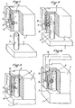
- La figure 1 est une vue perspective avec arrachement partiel, d'un exemple de réalisation du dispositif de l'invention, en position désaccouplée ;
- La figure 2 est une vue analogue au dispositif en cours d'accouplement ou de désaccouplement ;
- La figure 3 est une vue analogue en position de verrouillage ;
- La figure 4 illustre schématiquement un outillage de verrouillage et déverrouillage.
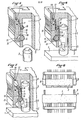
- Les figures 5, 6 et 7 sont des vues analogues d'une variante de réalisation.
- La figure 8 est une vue schématique d'un connecteur de forme cassette muni des dispositions de l'invention.
- Figure 1 is a perspective view with partial cutaway, of an exemplary embodiment of the device of the invention, in the uncoupled position;
- Figure 2 is a view similar to the device during coupling or uncoupling;
- Figure 3 is a similar view in the locked position;
- Figure 4 schematically illustrates a locking and unlocking tool.
- Figures 5, 6 and 7 are similar views of an alternative embodiment.
- Figure 8 is a schematic view of a cassette-shaped connector provided with the provisions of the invention.
En se reportant aux figures 1 à 4, on voit que le dispositif selon l'invention, qui peut être placé latéralement à un connecteur 1, 2 de forme quelconque, comporte une colonne cylindrique de guidage 3 sur la première partie 1 coopérant avec un logement de même section 4 placé sur la deuxième partie 2 ; la colonne 3 comporte une encoche de verrouillage 5 (de forme cylindrique) d'axe perpendiculaire à l'axe de la colonne 3, et la deuxième partie 2 comporte un rouleau cylindrique 6 logé avec débattement entre une position de verrouillage (figure 3) dans laquelle le rouleau 6 pénètre dans le logement 4 et coopère avec l'encoche 5 et une position d'accouplement (figure 2) dans laquelle le rouleau 6 est effacé hors du logement 4 ; le rouleau 6 est repoussé vers le logement 4 par une lame ressort 7 portée par un tiroir 8 coulissant sur la deuxième partie 2 ; le tiroir 8 porte en outre une surface 9 (arête ou bossage) formant butée repoussant et bloquant le rouleau 6 en position de verrouillage lorsque le tiroir est en position de verrouillage ; la deuxième partie 2 porte une butée 10 coopérant avec l'extrémité de la lame ressort 7 et bloquant le tiroir en position déverrouillée (figure 1) jusqu'à enfoncement de la lame 7 sous la poussée du rouleau 6 au cours de l'accouplement (figure 2).Referring to Figures 1 to 4, we see that the device according to the invention, which can be placed laterally to a
Le fonctionnement du dispositif est le suivant :
- Le connecteur désaccouplé est dans la position de la figure 1. Le
tiroir 8 est en position déverrouillée et ne peut pas être déplacé, lalame ressort 7 étant bloquée par labutée 10 ; lerouleau 6 est repoussé par lalame ressort 7 dans lelogement 4.
- The uncoupled connector is in the position of FIG. 1. The
drawer 8 is in the unlocked position and cannot be moved, theleaf spring 7 being blocked by thestop 10; theroller 6 is pushed back by thespring blade 7 into thehousing 4.
Lorsqu'on opère l'accouplement, la colonne 3 s'enfonce dans le logement 4 et vient repousser le rouleau 6 (figure 2) ; le rouleau 6 repousse la lame 7 qui se trouve alors dégagée de la butée 10 ; la surface de butée 9 vient en contact avec le rouleau 6.When the coupling is operated, the
Lorsque la deuxième partie 2 atteint la position d'accouplement et de verrouillage, le rouleau 6 tombe dans l'encoche 5 (figure 3) ; la surface de butée 9 repousse le rouleau 6 dans l'encoche 5 et le tiroir 8 peut coulisser et prendre la position de verrouillage de la figure 3. Dans cette position, le tiroir 8 découvre un repère visuel 14 de fin de verrouillage.When the
L'opération de déverrouillage s'effectue par une simple traction sur le tiroir 8 dont la translation libère le rouleau 6 et permet le désaccouplement.The unlocking operation is carried out by a simple pull on the
Plusieurs dispositifs tels que représentés- seront généralement prévus à la périphérie d'un connecteur, par exemple, s'agissant d'un connecteur en forme de cassette plate, un dispositif sur chaque petit côté du connecteur (figure 8).Several devices as shown will generally be provided at the periphery of a connector, for example, for a connector in the form of a flat cassette, a device on each short side of the connector (Figure 8).
L'accouplement et le désaccouplement peuvent être effectués par exemple par poussée manuelle sur le tiroir 8 ou par l'intermédiaire d'un outil spécifique 13 (figure 4) prenant appui sur le rebord 11 pour l'accouplement et sur l'épaulement 12 pour le désaccouplement. Dans l'exemple décrit, la colonne 3 présente une encoche 5 cylindrique d'axe horizontal. Cette encoche peut être remplacée par une gorge annulaire. Elle peut avoir une section circulaire (figures 1 à 4) ou pneumatique (figures 5 à 7).The coupling and uncoupling can be carried out for example by manual pushing on the
Dans la variante des figures 5 à 7, il est prévu deux rouleaux 6 et 16 logés à débattement dans la partie 1. Le rouleau 6 coopère avec l'encoche 5 comme dans les figures 1 à 4 ; le rouleau 16 est placé entre le rouleau 6 et le fond du logement 4 et il coopère avec le ressort 7 sous l'action de la colonne 3 déjà enfoncée au-delà du rouleau 6.In the variant of FIGS. 5 to 7, there are provided two
En outre, la surface 9 qui repousse le rouleau 6 en position de verrouillage est constituée par la face interne du tiroir 8 ; il est prévu une butée supplémentaire 18 sur la face externe de la partie 2 pour limiter le débattement du tiroir 8, lequel comporte une encoche ou logement 15 pour assurer le débattement du rouleau 6 en position déverrouillée (figures 5 et 6 ); enfin un ressort 17 sollicite constamment le tiroir 8 vers la position de verrouillage, de sorte que, lorsque le rouleau 16 est repoussé par la colonne 3 et que le rouleau 16 entre dans l'encoche 5, le tiroir prend automatiquement la position de verrouillage (figure 7).In addition, the
Ainsi, le tiroir 8 ne peut se déplacer vers la position de verrouillage tant que la colonne 3 n'a pas pénétré dans le logement 4 au-delà du rouleau 6 ; mais ensuite, dès que le rouleau 6 pénètre dans l'encoche 5, le tiroir 8 prend automatiquement la position de verrouillage sous l'action du ressort 17.Thus, the
Claims (4)
Priority Applications (1)
| Application Number | Priority Date | Filing Date | Title |
|---|---|---|---|
| AT84400651T ATE32001T1 (en) | 1983-04-15 | 1984-04-02 | LOCKING AND GUIDING ARRANGEMENT FOR THE TERMINATION OF A CONNECTOR. |
Applications Claiming Priority (2)
| Application Number | Priority Date | Filing Date | Title |
|---|---|---|---|
| FR8306207A FR2544560B1 (en) | 1983-04-15 | 1983-04-15 | DEVICE FOR GUIDING AND LOCKING THE COUPLING OF A CONNECTOR |
| FR8306207 | 1983-04-15 |
Publications (2)
| Publication Number | Publication Date |
|---|---|
| EP0122842A1 true EP0122842A1 (en) | 1984-10-24 |
| EP0122842B1 EP0122842B1 (en) | 1988-01-13 |
Family
ID=9287907
Family Applications (1)
| Application Number | Title | Priority Date | Filing Date |
|---|---|---|---|
| EP84400651A Expired EP0122842B1 (en) | 1983-04-15 | 1984-04-02 | Locking and guiding means for the mating of a connector |
Country Status (4)
| Country | Link |
|---|---|
| EP (1) | EP0122842B1 (en) |
| AT (1) | ATE32001T1 (en) |
| DE (1) | DE3468791D1 (en) |
| FR (1) | FR2544560B1 (en) |
Cited By (10)
| Publication number | Priority date | Publication date | Assignee | Title |
|---|---|---|---|---|
| GB2243183A (en) * | 1990-03-30 | 1991-10-23 | Andrew Glover | Security clamp, particularly for fire arms |
| US5129836A (en) * | 1991-06-24 | 1992-07-14 | Ursich Nels E | Self-locking female receptor for electrical cord |
| US5393239A (en) * | 1993-12-27 | 1995-02-28 | Nels E. Ursich | Self-locking female electrical socket having automatic release mechanism |
| GB2282841A (en) * | 1993-09-30 | 1995-04-19 | Eastcoast Group Limited The | Safety catch with a locking detent for pushchairs |
| US5413498A (en) * | 1991-06-24 | 1995-05-09 | Ursich; Nels E. | Self-locking female receptor for electrical cord |
| US5921798A (en) * | 1997-06-25 | 1999-07-13 | Ursich; Nels E. | Waterproof locking female electrical socket |
| US6048222A (en) * | 1997-12-10 | 2000-04-11 | Micron Electronics, Inc. | Retentive ribbon cable connector |
| US6098284A (en) * | 1997-12-10 | 2000-08-08 | Micron Electronics, Inc. | Method of retentively attaching a ribbon cable connector to a device |
| US6452793B1 (en) | 2001-01-26 | 2002-09-17 | Micron Technology, Inc. | Apparatuses and methods for preventing disengagement of electrical connectors in the assembly of computers |
| WO2017013284A1 (en) * | 2015-07-21 | 2017-01-26 | Ride On Consulting, S. L. | Anchoring system for bicycles |
Citations (3)
| Publication number | Priority date | Publication date | Assignee | Title |
|---|---|---|---|---|
| FR1353468A (en) * | 1962-02-14 | 1964-02-28 | Improvements to electrical connection devices, in particular to those comprising a multiplicity of pins and sockets | |
| FR1354923A (en) * | 1963-01-28 | 1964-03-13 | Socapex | Self-locking electrical connector |
| DE1465398A1 (en) * | 1963-12-06 | 1969-03-06 | Commissariat Energie Atomique | Electrical connection coupling for automatic coupling |
-
1983
- 1983-04-15 FR FR8306207A patent/FR2544560B1/en not_active Expired
-
1984
- 1984-04-02 AT AT84400651T patent/ATE32001T1/en not_active IP Right Cessation
- 1984-04-02 DE DE8484400651T patent/DE3468791D1/en not_active Expired
- 1984-04-02 EP EP84400651A patent/EP0122842B1/en not_active Expired
Patent Citations (3)
| Publication number | Priority date | Publication date | Assignee | Title |
|---|---|---|---|---|
| FR1353468A (en) * | 1962-02-14 | 1964-02-28 | Improvements to electrical connection devices, in particular to those comprising a multiplicity of pins and sockets | |
| FR1354923A (en) * | 1963-01-28 | 1964-03-13 | Socapex | Self-locking electrical connector |
| DE1465398A1 (en) * | 1963-12-06 | 1969-03-06 | Commissariat Energie Atomique | Electrical connection coupling for automatic coupling |
Cited By (18)
| Publication number | Priority date | Publication date | Assignee | Title |
|---|---|---|---|---|
| GB2243183A (en) * | 1990-03-30 | 1991-10-23 | Andrew Glover | Security clamp, particularly for fire arms |
| US5129836A (en) * | 1991-06-24 | 1992-07-14 | Ursich Nels E | Self-locking female receptor for electrical cord |
| US5281162A (en) * | 1991-06-24 | 1994-01-25 | Ursich Nels E | Self-locking female receptor for electrical cord |
| US5413498A (en) * | 1991-06-24 | 1995-05-09 | Ursich; Nels E. | Self-locking female receptor for electrical cord |
| GB2282841A (en) * | 1993-09-30 | 1995-04-19 | Eastcoast Group Limited The | Safety catch with a locking detent for pushchairs |
| GB2282841B (en) * | 1993-09-30 | 1996-06-19 | Eastcoast Group Limited The | Safety catch for infant pushchairs and the like |
| US5393239A (en) * | 1993-12-27 | 1995-02-28 | Nels E. Ursich | Self-locking female electrical socket having automatic release mechanism |
| US5921798A (en) * | 1997-06-25 | 1999-07-13 | Ursich; Nels E. | Waterproof locking female electrical socket |
| US6048222A (en) * | 1997-12-10 | 2000-04-11 | Micron Electronics, Inc. | Retentive ribbon cable connector |
| US6098284A (en) * | 1997-12-10 | 2000-08-08 | Micron Electronics, Inc. | Method of retentively attaching a ribbon cable connector to a device |
| US6452793B1 (en) | 2001-01-26 | 2002-09-17 | Micron Technology, Inc. | Apparatuses and methods for preventing disengagement of electrical connectors in the assembly of computers |
| US6628516B2 (en) | 2001-01-26 | 2003-09-30 | Micron Technology, Inc. | Apparatuses and methods for preventing disengagement of electrical connectors in the assembly of computers |
| US6823588B2 (en) | 2001-01-26 | 2004-11-30 | Micron Technology, Inc. | Methods for preventing disengagement of electrical connectors in the assembly of computers |
| US7107675B2 (en) | 2001-01-26 | 2006-09-19 | Micron Technology, Inc. | Methods for retaining an electrical connector in a receptacle on an electrical component in a computer |
| US7614149B2 (en) | 2001-01-26 | 2009-11-10 | Micron Technology, Inc. | Methods for assembling computers |
| US7707718B2 (en) | 2001-01-26 | 2010-05-04 | Micron Technology, Inc. | Methods for assembling computers |
| WO2017013284A1 (en) * | 2015-07-21 | 2017-01-26 | Ride On Consulting, S. L. | Anchoring system for bicycles |
| US10828991B2 (en) | 2015-07-21 | 2020-11-10 | Ride On Consulting, S.L. | Electric bicycles anchoring system |
Also Published As
| Publication number | Publication date |
|---|---|
| DE3468791D1 (en) | 1988-02-18 |
| ATE32001T1 (en) | 1988-01-15 |
| FR2544560A1 (en) | 1984-10-19 |
| EP0122842B1 (en) | 1988-01-13 |
| FR2544560B1 (en) | 1985-07-05 |
Similar Documents
| Publication | Publication Date | Title |
|---|---|---|
| EP0337856B1 (en) | Dismountable asssembly for electrical or electronic equipment comprising a casing, and its housing | |
| EP1729376B1 (en) | Locking lever mechanism for connector | |
| EP0122842B1 (en) | Locking and guiding means for the mating of a connector | |
| EP1357650B1 (en) | Connecting device for a electronic casing | |
| EP0625809A1 (en) | Electrical connector with insertion and extracting drawer | |
| CA2721122A1 (en) | Two-part payment terminal comprising an assembly device | |
| EP0633633A1 (en) | Card connector, especially for an electronic card | |
| KR950034928A (en) | Eject Mechanism Attached Card Edge Connector | |
| FR2805635A1 (en) | CARD READER AND MOBILE EQUIPMENT COMPRISING IT | |
| FR2830132A1 (en) | WATERPROOF CONNECTOR WITH JOINT COMPRESSION DEVICE | |
| FR2522180A1 (en) | DISC TRAINING DEVICE | |
| EP0333530B2 (en) | Connecting housing for microcircuit cards | |
| FR2555825A1 (en) | ELECTRICAL CONNECTOR WITH ARRACHABLE PLUG | |
| FR2648855A1 (en) | UNIVERSAL ASSEMBLY FOR TOP AND BOTTOM LOCKS, IN VERTICAL BAR OUTPUT DEVICES, AND TOP AND BOTTOM LOCKS FOR SUCH DEVICES | |
| KR101865165B1 (en) | Security USB hub having locking function | |
| FR2705170A1 (en) | Electrical connector with insertion and extraction bracket. | |
| EP0342070B1 (en) | Device for manoeuvering the clipping mechanism of a modular electrical apparatus | |
| FR2544158A1 (en) | ASSEMBLY DEVICE FOR COMPUTER SYSTEM | |
| FR2662284A1 (en) | Chain-based refundable deposit mechanism for shopping trolley | |
| EP3297099B1 (en) | Latch for locking a connector in an electrical and/or telecommunication network | |
| FR2610861A2 (en) | DEVICE FOR DRILLING WOOD PANELS FOR THEIR ANKLE ASSEMBLY | |
| FR2655187A1 (en) | Key-actuated moving part for a safety switch | |
| EP1069813B1 (en) | Electronic card front plate, electronic plate and its inserting or extracting method in a rack | |
| EP0083956B1 (en) | Actuating means for an angular indexing mechanism of a parallel ruler device | |
| EP4023830A1 (en) | Locking clip system for slab |
Legal Events
| Date | Code | Title | Description |
|---|---|---|---|
| PUAI | Public reference made under article 153(3) epc to a published international application that has entered the european phase |
Free format text: ORIGINAL CODE: 0009012 |
|
| AK | Designated contracting states |
Designated state(s): AT BE CH DE FR GB IT LI LU NL SE |
|
| 17P | Request for examination filed |
Effective date: 19841120 |
|
| GRAA | (expected) grant |
Free format text: ORIGINAL CODE: 0009210 |
|
| AK | Designated contracting states |
Kind code of ref document: B1 Designated state(s): AT BE CH DE FR GB IT LI LU NL SE |
|
| PG25 | Lapsed in a contracting state [announced via postgrant information from national office to epo] |
Ref country code: NL Effective date: 19880113 Ref country code: IT Free format text: LAPSE BECAUSE OF FAILURE TO SUBMIT A TRANSLATION OF THE DESCRIPTION OR TO PAY THE FEE WITHIN THE PRESCRIBED TIME-LIMIT;WARNING: LAPSES OF ITALIAN PATENTS WITH EFFECTIVE DATE BEFORE 2007 MAY HAVE OCCURRED AT ANY TIME BEFORE 2007. THE CORRECT EFFECTIVE DATE MAY BE DIFFERENT FROM THE ONE RECORDED. Effective date: 19880113 Ref country code: AT Effective date: 19880113 |
|
| REF | Corresponds to: |
Ref document number: 32001 Country of ref document: AT Date of ref document: 19880115 Kind code of ref document: T |
|
| PG25 | Lapsed in a contracting state [announced via postgrant information from national office to epo] |
Ref country code: SE Effective date: 19880131 |
|
| REF | Corresponds to: |
Ref document number: 3468791 Country of ref document: DE Date of ref document: 19880218 |
|
| PG25 | Lapsed in a contracting state [announced via postgrant information from national office to epo] |
Ref country code: LU Free format text: LAPSE BECAUSE OF NON-PAYMENT OF DUE FEES Effective date: 19880430 |
|
| NLV1 | Nl: lapsed or annulled due to failure to fulfill the requirements of art. 29p and 29m of the patents act | ||
| GBV | Gb: ep patent (uk) treated as always having been void in accordance with gb section 77(7)/1977 [no translation filed] | ||
| BERE | Be: lapsed |
Owner name: S.A. CIE DEUTSCH Effective date: 19880430 |
|
| PLBE | No opposition filed within time limit |
Free format text: ORIGINAL CODE: 0009261 |
|
| STAA | Information on the status of an ep patent application or granted ep patent |
Free format text: STATUS: NO OPPOSITION FILED WITHIN TIME LIMIT |
|
| PG25 | Lapsed in a contracting state [announced via postgrant information from national office to epo] |
Ref country code: GB Free format text: LAPSE BECAUSE OF NON-PAYMENT OF DUE FEES Effective date: 19881122 |
|
| 26N | No opposition filed | ||
| PG25 | Lapsed in a contracting state [announced via postgrant information from national office to epo] |
Ref country code: BE Effective date: 19890430 |
|
| PGFP | Annual fee paid to national office [announced via postgrant information from national office to epo] |
Ref country code: CH Payment date: 19950222 Year of fee payment: 12 |
|
| PGFP | Annual fee paid to national office [announced via postgrant information from national office to epo] |
Ref country code: FR Payment date: 19950227 Year of fee payment: 12 |
|
| PGFP | Annual fee paid to national office [announced via postgrant information from national office to epo] |
Ref country code: DE Payment date: 19950620 Year of fee payment: 12 |
|
| PG25 | Lapsed in a contracting state [announced via postgrant information from national office to epo] |
Ref country code: LI Effective date: 19960430 Ref country code: DE Free format text: LAPSE BECAUSE OF NON-PAYMENT OF DUE FEES Effective date: 19960430 Ref country code: CH Effective date: 19960430 |
|
| REG | Reference to a national code |
Ref country code: CH Ref legal event code: PL |
|
| PG25 | Lapsed in a contracting state [announced via postgrant information from national office to epo] |
Ref country code: FR Effective date: 19961227 |
|
| REG | Reference to a national code |
Ref country code: FR Ref legal event code: ST |