EP0124093A2 - Pre-assembled modular unit for the driver's area of motor vehicles, particularly passenger cars, and method of installing such a pre-assembled modular unit - Google Patents
Pre-assembled modular unit for the driver's area of motor vehicles, particularly passenger cars, and method of installing such a pre-assembled modular unit Download PDFInfo
- Publication number
- EP0124093A2 EP0124093A2 EP84104712A EP84104712A EP0124093A2 EP 0124093 A2 EP0124093 A2 EP 0124093A2 EP 84104712 A EP84104712 A EP 84104712A EP 84104712 A EP84104712 A EP 84104712A EP 0124093 A2 EP0124093 A2 EP 0124093A2
- Authority
- EP
- European Patent Office
- Prior art keywords
- end wall
- unit according
- cross member
- assembled unit
- pillar
- Prior art date
- Legal status (The legal status is an assumption and is not a legal conclusion. Google has not performed a legal analysis and makes no representation as to the accuracy of the status listed.)
- Granted
Links
Images


Classifications
-
- B—PERFORMING OPERATIONS; TRANSPORTING
- B62—LAND VEHICLES FOR TRAVELLING OTHERWISE THAN ON RAILS
- B62D—MOTOR VEHICLES; TRAILERS
- B62D65/00—Designing, manufacturing, e.g. assembling, facilitating disassembly, or structurally modifying motor vehicles or trailers, not otherwise provided for
- B62D65/02—Joining sub-units or components to, or positioning sub-units or components with respect to, body shell or other sub-units or components
- B62D65/14—Joining sub-units or components to, or positioning sub-units or components with respect to, body shell or other sub-units or components the sub-units or components being passenger compartment fittings, e.g. seats, linings, trim, instrument panels
-
- B—PERFORMING OPERATIONS; TRANSPORTING
- B62—LAND VEHICLES FOR TRAVELLING OTHERWISE THAN ON RAILS
- B62D—MOTOR VEHICLES; TRAILERS
- B62D25/00—Superstructure or monocoque structure sub-units; Parts or details thereof not otherwise provided for
- B62D25/08—Front or rear portions
- B62D25/081—Cowls
-
- B—PERFORMING OPERATIONS; TRANSPORTING
- B62—LAND VEHICLES FOR TRAVELLING OTHERWISE THAN ON RAILS
- B62D—MOTOR VEHICLES; TRAILERS
- B62D25/00—Superstructure or monocoque structure sub-units; Parts or details thereof not otherwise provided for
- B62D25/08—Front or rear portions
- B62D25/14—Dashboards as superstructure sub-units
Definitions
- the invention relates to a preassembled unit for the cockpit area of motor vehicles, in particular passenger cars, which can be assembled as a whole within the body of the vehicle and essentially comprises the following units: a dashboard, including all internals, fuse box and electrical wiring, heating with Actuation and air distribution system, antenna; also a steering system with steering wheel, steering gear, steering wheel cover and steering bracket; as well as pedals for clutch and brake as well as accelerator pedal, each with - pedals; Brake booster, wiper system, heater blower, air conditioning u.
- the body has an end wall with end wall cross member (so-called steering cross member), with which the above-mentioned units - directly or indirectly - are connected in the installed state.
- the cockpit zone is the most assembly-intensive area of the body.
- the most diverse units for operating, controlling and monitoring the vehicle are piling up here.
- the facilities serving comfort, such as heating and ventilation, radio etc. are mainly concentrated in the cockpit area.
- a preassembled unit of the type mentioned at the beginning also referred to in the technical language as a cockpit module, has become known from US Pat. No. 4,126,202.
- the known cockpit module which is intended for tractors, is based on a box-like frame on which the dashboard, the steering, the pedals and other units and instruments assigned to the passenger compartment are combined to form a unit which can be assembled in its entirety in the body of the tractor .
- the object of the present invention is to take suitable measures in a preassembled structural unit of the type described at the outset to ensure that the essential assemblies and components which are to be attributed to the cockpit area and which are seated beyond the end wall, i.e. engine compartment side, can be integrated into the pre-assembled unit.
- the object is achieved in that the end wall and end wall cross member are separated from the body-in-white and serve as a preassembly base for the structural unit, and in that in the installed position of the unit end wall and end wall cross member can be sealingly connected to the laterally adjacent body walls.
- important procedural measures of the invention for the installation of the preassembled structural unit according to the invention consist in that the preassembled structural unit is inserted from top to bottom through the windshield opening in the body and is then sealingly connected to the adjacent body walls on the end wall and end wall cross member.
- the windshield and bonnet are therefore only assembled after the preassembled unit has been installed.
- the invention makes it possible, in particular include the following important units and components in the preassembled unit: steering gear, booster, brake pedal adjustment, windshield wiper system with drive motor, heating blower, air conditioning blower with air routing, Bowden cables for hood, headlight regulation, etc., engine compartment insulation mat, passenger compartment insulation mat, water canister, windshield washer system and headlamp radiator, water compensation tank Console (passenger compartment) as well as all other parts that are arranged outside or inside on the bulkhead according to the vehicle equipment, e.g. electrical, electronic components (process computer, ABV system, etc.).
- the essential idea of the invention is therefore to no longer consider the end wall and end wall cross member as fixed components of the body-in-white or to assign them to the body, but rather to use them as detachments from the body-in-white as a pre-assembly base for the cockpit. It has thus become possible to pre-assemble all parts and components that are arranged in front of or behind the bulkhead, or that are passed through the bulkhead, on the outside of the body on a special (assembly-optimized) assembly line to form a complete cockpit assembly (cockpit module) and then insert this assembly into the bodyshell from top to bottom.
- Another advantage of the invention is that a separate mounting frame is no longer required, which would have to be removed from the body after the final assembly of the structural unit. This is because the function of a "mounting frame" is, according to the invention, taken over by the bulkhead and bulkhead crossmember, which of course remain in the body as important components of the body after the final assembly.
- the invention also advantageously blinds operations are avoided and the error rate is reduced considerably. All assembly operations can be carried out in normal posture. Unfavorable postures, as would be required during assembly processes within the body, can thus advantageously be avoided by the invention.
- the preassembled unit according to the invention can be subjected to a function test before being installed in the car. Possible errors can be identified and localized on a diagnostic test bench using a central multiple connector, which connects the entire electrical system with the main cable set after installation, and can be quickly and easily remedied.
- FIG. 1-5 denotes 10 a pre-assembled body shell of a passenger car.
- An opening in the body 10 provided for the front window (windshield) is numbered 11.
- the engine compartment is open at the top (bonnet not yet installed) bears the reference number 12 overall.
- the so-called A-pillars forming the lateral closure of the windshield opening 11 are designated 13 and 14.
- the substructure 15 with the transmission tunnel 16, including the side walls 17 forming the so-called wheel installation, can also be seen within the body 10.
- FIG. 1 Floating somewhat above the body 10 (the carrying device is not shown), a preassembled structural unit, designated overall by 18, is shown in FIG. 1.
- This is the cockpit area of the vehicle, also referred to as the cockpit module.
- the preassembled unit 18 accordingly not only includes the aggregates of the cockpit area on the passenger compartment side, but also those aggregates which are located beyond the end wall 19, that is to say on the engine compartment side.
- the end wall 19 consists of a sheet which is bent several times. After an approximately vertical course (the actual body end wall), the sheet 19 is bent approximately at right angles backwards and then up again and forms there - together with a further sheet metal part 29 welded on at 28 - the so-called water box 30
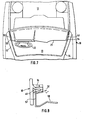
- a cross section forming an inverted U, a box-shaped end wall cross member in the middle section and numbered 20 overall is - as also shown in FIG. 3 - also partially formed from the end wall plate 19.
- the one U-leg of the end wall cross member 20 is the already mentioned upper end 31 of the end wall plate 19, to which - at 32 - a separate sheet metal part 33 forming the other U leg of the end wall cross member 20 is welded.
- the end wall cross member 20 can be screwed to the body 10 on both sides in its final assembly position.
- the two A-pillars 13, 14 of the body 10 each have a carrier connection designated overall by 34.
- the carrier connections 34 are each molded out of the assigned A-pillar (13 or 14) on the one hand and the wheel installation 17 (see FIG. 1) on the other hand.
- the part of the carrier connection 34 assigned to the A-pillar 13 is designated by 35 in FIG. 4, whereas the part of the carrier connection 34 assigned to the wheel installation 17 is numbered 36 there.
- a part of the windshield (windshield) is shown in FIG. 4 and numbered 37.
- the end wall cross member 20 is screwed to the carrier connections 34, as can be seen in particular in FIG. 6, by means of two screws 38, 39, the two screw bushings 40, 41 or 42, 43 provided for this purpose on the respective carrier connection 34 or respectively Enforce the associated end of the bulkhead cross member 20.
- Fig. 6 makes it clear that the screws 38, 39 have conical bevels 44 on their heads, which cooperate with corresponding conical recesses 45 in the carrier connections 34, such that when the screws 38, 39 are tightened, a so-called cone passage of the inclined surfaces 44 surrounding area of the end wall cross member plate 31.
- At the ends of the screws 38, 39 there is also a corresponding tapering of the regions of the sheet metal 33 of the end wall cross member 20 surrounding the screws 38, 39.
- the carrier connections 34 are each provided with a disk flange 49, which is used to hold glued windshields or to hold a window mount rubber.
- the end wall cross member 20 is also formed at its upper edge as a disc flange (reference numeral 32), in such a way that Complement the disk flanges 49 of the carrier connections 34 and the disk flange 32 of the bulkhead cross member 20 in the assembly position to form the entire disk flange.
- the disk flange parts 49 assigned to the carrier connections 34 each have a stepped extension on both sides (cf. in particular FIG.
- the dashboard 21 must be bevelled on both sides at 52, 53 so that its contours correspond to the corresponding dimensions of the front window opening 11, which also has inclined surfaces on the sides.
- This eliminates the first of the dashboard - 21 in Figure 7 is indicated by dashed lines triangular side portions 54, 55.
- the entire end wall 19 has a flange-like edge 56 bent in the horizontal direction has, by means of which it is to be fastened in a sealing manner to an appropriately designed edge 57 on the adjacent body walls 15.
- the cooperating edges 56, 57 of the end wall 19 and adjacent body walls 15, 17 - starting from the disk flange 32, 49 and running all the way around the wheel installation 17 and substructure 15 - form a sealing channel 58 which can be filled with hardening sealant , and can be connected to one another below the sealing channel 58.
- FIGS. 9 and 10 Two possible embodiments for the formation of the sealing channel 58 in detail can be seen from FIGS. 9 and 10.
- the sealing channel is numbered 58 a.
- the end wall 19a is double-walled at its edge 56a, the two wall parts designated 59, 60 forming the sealing channel 58a.
- the edge of the body substructure 15, 17, designated 57a projects into the sealing channel 58a from below.
- the adhesive 61 filled into the sealing channel 58a can be a polyurethane adhesive, which can also be used for gluing in the front pane 37.
- the firm connection of the edges 56a and 57a of the end wall 19a on the one hand and the vehicle substructure 15, 17 on the other hand finally takes place by means of screws, one of which is shown in FIG. 9 and numbered 62.
- the body edge 57b provided for connection to the edge 56b of the end wall 19b is double-walled, it having two wall parts 63, 64 which enclose the sealing channel 58b between them.
- the sealing channel 58b is filled with curable adhesive 61, for example a polyurethane adhesive.
- the one that serves as an adhesive flange into which hardens Bare adhesive 61 protruding edge 56b of the end wall 19b is provided with embossed spacers 65. This ensures that the flange-like edges 56b and 57b are bonded on both sides particularly well.
- a screw connection of the two edges 56b and 57b is not provided in this embodiment and is also not required.
- FIG. 11 also shows two possible variants for the formation of the water box 30.
- the water tank 30 can - as shown in solid lines - be closed on both sides at a distance from the body side wall 17.
- FIG. 12 illustrates the more conventional design of the end wall 19 and the end wall cross member 20 from several sheet metal parts, which - as can be seen from FIG. 3 - can be put together.
- the design of the individual sheet metal parts differs somewhat from the embodiment according to FIG. 3.
- the sheet metal parts 29a and 31a forming the water box 30 are formed in one piece in FIG. 12, whereas the water box 30 in the embodiment according to FIG. 3 consists of two sheets 29, 31 welded together at 28.
- the end wall cross member is also made up of two in the embodiment according to FIG. 12 Sheet metal parts - designated 31a and 33a - together, which can be connected to one another at their upper edges 32a and 32b.
- the embodiment according to FIG. 13 differs considerably from this.
- the special feature here is in particular that the parts forming the end wall 19c and the end wall cross member 20c are all made of plastic material. This advantageously reduces the total number of individual parts to be joined together to form the end wall / end wall cross member to only three.
- the water box is here, similar to the embodiment according to FIG. 3, formed by the end wall part 19c, which is bent several times, with its end part 29c, to which a separate wall part 29c is fastened.
- the end wall cross member 20c is composed of the parts 29c and 33c which are connected to one another at the upper edges 32c 'and 32c ", preferably welded together.
- an opening of the body 110 provided for the windshield (windshield) is numbered 111.
- the engine compartment which is open towards the top, bears the overall reference number 112.
- the so-called A-pillars which form the lateral closure of the windshield opening 111, are designated by 113 and 114.
- the substructure 115 with the transmission tunnel 116 including the so-called wheel installation side walls 117.
- the preassembled structural unit designated here overall by 118, is shown in FIG. 14. As in the embodiment according to FIG. 1, this is the cockpit area of the vehicle, also referred to as the cockpit module.
- An essential component of the structural unit 118 is a body end wall 119 with an end wall cross member 120 adjoining it at the top.
- a closing plate 128 or 129 is attached to the end wall cross member 120 - at its two ends adjacent to the side body walls (A-pillars 113, 114).
- the locking plates 128, 129 come into contact with the inner sheets (lateral end walls) 130 and 131 of the respective A-pillars 113 and 114, respectively.
- the assembly 118 is fastened in its assembly position by screwing by means of fastening screws directed in the transverse direction of the vehicle, one of which is shown in a separate position in FIG. 14 and numbered 132.
- the inner sheets 130, 131 of the A-pillars 113, 114 each have two approximately vertically one above the other horizontal through bores 133, 134 for the fastening screws 132.
- FIG. 15 now illustrates - in an enlarged representation compared to FIG. 14 - a possible embodiment of the locking plate designated here with 128a. 15 also shows a possible variant of fastening the locking plate 128a to the associated inner sheet 130a of the left A-pillar 113.
- FIG. 15 shows here that the A-pillar 113 - as usual - from the inside already mentioned lying sheet 130a and an outer wall numbered 135.
- the two sheet metal parts 130a and 135 forming the A-pillar 113 are spot-welded to one another at 136 and 137. They form flanges 138, 139.
- a flange cover 140 is pushed onto the flange 138, on which a front door seal 141 which is ring-shaped in section is formed.
- a cavity that forms in the interior of the A-pillar 113 is designated by 142.
- the contours of the closing plates 128 (128a) and 129 are matched to the shape of the adjacent A-pillars 113 and 114 in such a way that when the structural unit 118 is installed the same is automatically centered with respect to the body 110.
- the striker plates in this case the striker plate 128a
- the extensions 143, 144 each partially encompass a front and a rear guide shoulder - 145 and 146 - of the A-pillar 113.
- the inner sheets 130, 131 of the A-pillars 113, 114 are in Direction from top to bottom slightly converging conical.
- the angle of inclination of the closing plates 128 (or 128a) and 129 corresponds to the aforementioned inclined position of the associated inner sheets 130, 131 of the relevant A-column len 113 or 114. As a result, when the assembly 118 is installed, it is automatically centered with respect to the longitudinal center axis of the body 110.
- front and rear guide shoulders - numbered 145 and 146 in FIG. 15 - of the respective A-pillars 113 and 114 are arranged diverging from one another in the direction from top to bottom. In cooperation with the respectively assigned locking plate (e.g. 128a in Fig. 15), this results in an automatic centering of the assembly 118 when it is installed in the body 110, also in the longitudinal direction of the vehicle.
- the embodiment shown in FIG. 15 is further characterized in that the locking plate extension 143, which interacts with the front guide shoulder 145 of the A-pillar 113, is bent backwards by a total of approximately 180 ° and seals into one on the front of the front guide shoulder 145 trained channel 147 engages.
- the channel 147 which is open towards the front, is formed between a bent portion 148 of the front A-pillar guide shoulder, 145 and a correspondingly bent sheet metal part 150 which is spot-welded to the guide shoulder 145 at 149. 15 also shows that the channel 147 is filled with a curable adhesive 151 and thus functions as a sealing channel for a sealing connection between the parts 128a and 130a or, 113.
- the parts 143, 145 and 147-151 is advantageously by the described interaction of a g e-know hooking of the end wall of the cross member 120 with the respective associated A-pillar (for example, 113 in Fig. 15) is reached, which in particular in a possibly collision, of the vehicle with regard to the high strength of the connection between the assembly 118 and the vehicle body 110 has a favorable effect.
- FIG. 15 also shows one possibility of how the connection between the end wall cross member 120 and the A-pillars 113 and 114 can be designed in detail.
- the fastening screw 132 used for screwing the closing plate 128a the A-pillar 113 is completely penetrated from the outside inwards and its head 152 is supported on the outer wall 135 of the A-pillar 113.
- the forces that occur when the screw 152 is tightened would naturally cause the walls 130a and 135 of the A-pillar 113 to move undesirably towards one another.
- a spacer sleeve 156 is arranged within the cavity 142 of the A-pillar 113 - extending from the inner wall 130a to the outer wall 135 - which concentrically encloses the fastening screw 132 within the cavity 142.
- corresponding constructive measures are also provided for the other fastening screws, not shown in FIG. 15.
- the embodiment of the connection according to FIG. 15 is a so-called two-section connection.
- FIG. 16 shows another embodiment of a connection between the end wall cross member 120 and the A-pillar 113.
- a screw nut 155b is fastened to the inside of the locking plate 128b and has a conical recess 157.
- the inner sheet 130b of the A-pillar 113b and the closing plate 128b form a recess 158, which is penetrated by a fastening screw 132b.
- the mounting screw 132b cooperating with the nut 155b is enforced.
- the fastening screw 132b cooperating with the nut 155b has a head 152b with a conical bevel 159.
- the screw head 152b When the fastening screw 132b is tightened, the screw head 152b is supported on the inner sheet metal 130b of the A-pillar 113b. Because of the conical bevel 159, the area of the locking plate 128b surrounding the screw is plastically deformed, as can be seen at 160, and pressed into the hollow-conical recess 157 of the screw nut 155b. This creates a so-called conical thread, which ensures particularly good strength between the two connected parts 128b and 113b and thus the structural unit 118 with the A-pillar 113.
- recesses 161 are provided in the outer wall 135b, which are separated by a plug 162, e.g. can consist of rubber or a similar material, can be closed from the outside.
- connection of the parts 128b and 113b shown in FIG. 16 is a so-called one-cut screw connection.
Abstract
Description
Die Erfindung bezieht sich auf eine vormontierte Baueinheit für den Cockpit-Bereich von Kraftfahrzeugen, insbesondere Personenkraftwagen, die als Ganzes innerhalb der Karosserie des Fahrzeuges montierbar ist und im wesentlichen folgende Aggregate umfaßt: eine Armaturentafel, einschließlich aller Einbauten, Sicherungskasten und elektrischer Verkabelung, Heizung mit Betätigung und Luftverteilungssystem, Antenne; ferner eine Lenkung mit Lenkrad, Lenkgetriebe, Lenkradverkleidung und Lenkungshalter; sowie Pedale für Kupplung und Bremse sowie Fahrpedal, jeweils mit-Pedalböcken; Bremskraftverstärker, Scheibenwischeranlage, Heizungsgebläse, Klimaanlage u. dgl., und wobei die Karosserie eine Stirnwand mit Stirnwandquerträger (sogenannter Lenkungsquerträger) aufweist, mit der die genannten Aggregate - unmittelbar oder mittelbar - im eingebauten Zustand verbunden sind.The invention relates to a preassembled unit for the cockpit area of motor vehicles, in particular passenger cars, which can be assembled as a whole within the body of the vehicle and essentially comprises the following units: a dashboard, including all internals, fuse box and electrical wiring, heating with Actuation and air distribution system, antenna; also a steering system with steering wheel, steering gear, steering wheel cover and steering bracket; as well as pedals for clutch and brake as well as accelerator pedal, each with - pedals; Brake booster, wiper system, heater blower, air conditioning u. Like., And wherein the body has an end wall with end wall cross member (so-called steering cross member), with which the above-mentioned units - directly or indirectly - are connected in the installed state.
Bei der Herstellung von Kraftfahrzeugen besteht zunehmend das Bestreben, einzelne Teile nicht mehr separat zu montieren, sondern mehrere Teile zu vormontierten Baugruppen zusammenzufassen und diese größeren Baueinheiten dann im Fahrzeug einzubauen. Hierdurch können Verbesserungen und Erleichterungen der Arbeitsbedingungen und Montageoperationen erreicht werden.There is an increasing number of vehicles the endeavor to no longer assemble individual parts separately, but to combine several parts into preassembled modules and then to install these larger units in the vehicle. As a result, improvements and easing of working conditions and assembly operations can be achieved.
Bei Kraftfahrzeugen, insbesondere Personenkraftwagen, ist die Cockpit-Zone der montageintensivste Bereich der Karosserie. Hier häufen sich die verschiedensten Aggregate zur Betätigung, Steuerung und Kontrolle des Fahrzeuges. Aber auch die dem Komfort dienenden Einrichtungen, wie Heizung und Lüftung, Radio usw. sind vorwiegend im Cockpit-Bereich konzentriert.In the case of motor vehicles, in particular passenger cars, the cockpit zone is the most assembly-intensive area of the body. The most diverse units for operating, controlling and monitoring the vehicle are piling up here. But also the facilities serving comfort, such as heating and ventilation, radio etc., are mainly concentrated in the cockpit area.
Eine vormontierte Baueinheit der eingangs genannten Art, in der Fachsprache auch als Cockpit-Modul bezeichnet, ist durch die US-PS 4 126 202 bekannt geworden. Der bekannte Cockpit-Modul, der für Traktoren vorgesehen ist, basiert auf einem kastenartigen Rahmen, an dem die Armaturentafel, die Lenkung, die Pedale und andere der Fahrgastzelle zugeordnete Aggregate und Instrumente zu einer in ihrer Gesamtheit in der Karosserie des Traktors montierbaren Baueinheit zusammengefaßt sind.A preassembled unit of the type mentioned at the beginning, also referred to in the technical language as a cockpit module, has become known from US Pat. No. 4,126,202. The known cockpit module, which is intended for tractors, is based on a box-like frame on which the dashboard, the steering, the pedals and other units and instruments assigned to the passenger compartment are combined to form a unit which can be assembled in its entirety in the body of the tractor .
Eine weitere vormontierte Baueinheit der eingangs bezeichneten Art ist durch die deutsche Patentanmeldung P 31 49 083.2-21 Stand der Technik geworden. Hierbei werden eine ganze Anzahl von Aggregaten und Komponenten des Cockpit-Bereichs auf einem Rahmen vormontiert, der nach Montage der Baueinheit im Fahrzeug anschließend wieder aus der Karosserie entfernt wird. Eine Stirnwand-Schließplatte ermöglicht es, einige wichtige Aggregate und Kabelbündel aus dem Fahrgastraum durch die Stirnwand in den Motorraum hindurchzuführen.Another preassembled unit of the type described in the introduction has become state of the art through the German
Durch die bekannten Maßnahmen wird zwar bereits eine erhebliche Vereinfachung und Erleichterung bei der Fahrzeugmontage insgesamt erreicht. Dennoch bleiben für den Cockpit-Bereich weiterhin schwierige, im einzelnen am Fahrzeug selbst vorzunehmende Montageoperatiönen bestehen. Dies wird deutlich, wenn man sich vergegenwärtigt, daß der Cockpit-Bereich ja nicht nur die fahrgastraumseitigen Betätigungselemente, Aggregate, Instrumente usw. umfaßt. Wichtige weitere Aggregate und Komponenten des Cockpit-Bereichs befinden sich vielmehr auch jenseits der Stirnwand, d.h. motorraumseitig, oder müssen vom Fahrgastraum kommend durch die Stirnwand hindurch in den Motorraum geführt und dort fertigmontiert werden.The known measures already considerably simplify and simplify driving total tool assembly achieved. Nevertheless, difficult assembly operations that still have to be carried out on the vehicle itself remain for the cockpit area. This becomes clear when one realizes that the cockpit area does not only include the actuators, units, instruments, etc. on the passenger compartment side. Rather, other important components and components of the cockpit area are located beyond the end wall, ie on the engine compartment side, or must come from the passenger compartment through the end wall into the engine compartment and be assembled there.
Aufgabe der vorliegenden Erfindung ist es, bei einer vormontierten Baueinheit der eingangs bezeichneten Art geeignete Maßnahmen dafür zu treffen, daß auch die dem Cockpit-Bereich zuzurechnenden wesentlichen Aggregate und Komponenten, die ihren Sitz jenseits der Stirnwand, d.h. motorraumseitig, haben, in die vormontierte Baueinheit integriert werden können.The object of the present invention is to take suitable measures in a preassembled structural unit of the type described at the outset to ensure that the essential assemblies and components which are to be attributed to the cockpit area and which are seated beyond the end wall, i.e. engine compartment side, can be integrated into the pre-assembled unit.
Erfindungsgemäß wird die Aufgabe dadurch gelöst, daß Stirnwand und Stirnwandquerträger von der Rohkarosserie getrennt sind und als Vormontagebasis für die Baueinheit dienen, und daß in Einbaulage der Baueinheit Stirnwand und Stirnwandquerträger mit den seitlich jeweils angrenzenden Karosseriewänden dichtend verbindbar sind.According to the invention the object is achieved in that the end wall and end wall cross member are separated from the body-in-white and serve as a preassembly base for the structural unit, and in that in the installed position of the unit end wall and end wall cross member can be sealingly connected to the laterally adjacent body walls.
Im Zusammenhang damit bestehen wichtige Verfahrensmaßnahmen der Erfindung für den-Einbau der erfindungsgemässen vormontierten Baueinheit darin, daß die vormontierte Baueinheit von oben nach unten durch die Windschutzscheibenöffnung der Karosserie eingefahren und anschließend an Stirnwand und Stirnwandquerträger mit den angrenzenden Karosseriewänden dichtend verbunden wird. Windschutzscheibe und Motorhaube werden also erst nach Einbau der vormontierten Baueinheit montiert.In connection with this, important procedural measures of the invention for the installation of the preassembled structural unit according to the invention consist in that the preassembled structural unit is inserted from top to bottom through the windshield opening in the body and is then sealingly connected to the adjacent body walls on the end wall and end wall cross member. The windshield and bonnet are therefore only assembled after the preassembled unit has been installed.
Durch die Erfindung wird es möglich, insbesondere noch folgende wichtige Aggregate und Komponenten in die vormontierte Baueinheit mit einzubeziehen: Lenkgetriebe, Booster, Bremspedaleinstellung, Scheibenwischeranlage mit Antriebsmotor, Heizungsgebläse, Gebläse Klimaanlage mit Luftführung, Bowdenzüge für Haube, Scheinwerferregulierung u.a., Isolationsmatte Motorraum, Isolationsmatte Fahrgastraum, Wasserkanister, Scheibenwaschanlage und Scheinwerferreinigung, Wasserausgleichsbehälterkühler, Konsole (Fahrgastraum) sowie darüber hinaus alle weiteren Teile, die entsprechend der Fahrzeugausrüstung an der Stirnwand außen oder innen angeordnet sind, z.B. elektrische, elektronische Komponenten (Prozeßrechner, ABV Anlage usw.).The invention makes it possible, in particular include the following important units and components in the preassembled unit: steering gear, booster, brake pedal adjustment, windshield wiper system with drive motor, heating blower, air conditioning blower with air routing, Bowden cables for hood, headlight regulation, etc., engine compartment insulation mat, passenger compartment insulation mat, water canister, windshield washer system and headlamp radiator, water compensation tank Console (passenger compartment) as well as all other parts that are arranged outside or inside on the bulkhead according to the vehicle equipment, e.g. electrical, electronic components (process computer, ABV system, etc.).
Der wesentliche Gedanke der Erfindung besteht also darin, Stirnwand und Stirnwandquerträger nicht mehr als feste Bestandteile der Rohkarosserie zu betrachten bzw. dieser zuzuordnen, sondern - losgelöst von der Rohkarosserie - als Vormontagebasis für das Cockpit zu verwenden. Es ist damit möglich geworden, alle Teile und Komponenten, die vor oder hinter der Stirnwand angeordnet sind, oder durch die Stirnwand hindurchgeführt werden, außerhalb der Karosserie an einem speziellen (montageoptimierten) Montageband zu einer kompletten Cockpit-Baueinheit (Cockpit-Modul) vorzumontieren und diese Baueinheit anschließend von oben nach unten in die Rohkarosserie einzusetzen.The essential idea of the invention is therefore to no longer consider the end wall and end wall cross member as fixed components of the body-in-white or to assign them to the body, but rather to use them as detachments from the body-in-white as a pre-assembly base for the cockpit. It has thus become possible to pre-assemble all parts and components that are arranged in front of or behind the bulkhead, or that are passed through the bulkhead, on the outside of the body on a special (assembly-optimized) assembly line to form a complete cockpit assembly (cockpit module) and then insert this assembly into the bodyshell from top to bottom.
Ein weiterer Vorteil der Erfindung besteht darin, daß kein separater Montagerahmen_mehr benötigt wird, der nach der Endmontage der Baueinheit wieder aus der Karosserie entfernt werden müßte. Denn die Funktion eines "Montagerahmens" wird ja erfindungsgemäß von Stirnwand und Stirnwandquerträger übernommen, die nach der Endmontage der Baueinheit als wichtige Bestandteile der Karosserie selbstverständlich in derselben verbleiben.Another advantage of the invention is that a separate mounting frame is no longer required, which would have to be removed from the body after the final assembly of the structural unit. This is because the function of a "mounting frame" is, according to the invention, taken over by the bulkhead and bulkhead crossmember, which of course remain in the body as important components of the body after the final assembly.
Durch die Erfindung werden weiterhin vorteilhaft Blindoperationen vermieden und damit eine erhebliche Reduzierung der Fehlerrate ermöglicht. Alle Montageoperationen können in normaler Körperhaltung ausgeführt werden. Ungünstige Körperhaltungen, wie sie bei Montagevorgängen innerhalb der Karosserie erforderlich wären, lassen sich also durch die Erfindung vorteilhaft vermeiden.The invention also advantageously blinds operations are avoided and the error rate is reduced considerably. All assembly operations can be carried out in normal posture. Unfavorable postures, as would be required during assembly processes within the body, can thus advantageously be avoided by the invention.
Die erfindungsgemäße vormontierte Baueinheit kann vor dem Einbau in den Wagen einem Funktionstest unterzogen werden. Mögliche Fehler können hierbei über einen zentralen Vielfachstecker, welcher nach dem Einbau die gesamte Elektrik mit dem Hauptkabelsatz verbindet, auf einem Diagnoseprüfstand ermittelt und lokalisiert werden und lassen sich schnell und leicht beheben.The preassembled unit according to the invention can be subjected to a function test before being installed in the car. Possible errors can be identified and localized on a diagnostic test bench using a central multiple connector, which connects the entire electrical system with the main cable set after installation, and can be quickly and easily remedied.
Zusammenfassend kann gesagt werden, daß durch die mit der Erfindung geschaffenen verbesserten Montagebedingungen, einschließlich des damit möglichen umfassenden Funktionstests die Fehlerrate der betreffenden Serienfahrzeuge erheblich reduziert wird, aufwendige und kostspielige Nacharbeiten somit weitgehend vermieden werden können. In Verbindung mit verbesserter Produktivität und verbesserten ergonomischen Arbeitsbedingungen wird eine Steigerung der Zuverlässigkeit der betreffenden Fahrzeuge erzielt.In summary, it can be said that the improved assembly conditions created with the invention, including the comprehensive function test that is possible with it, considerably reduces the error rate of the series vehicles in question, and complex and expensive reworking can thus be largely avoided. In conjunction with improved productivity and improved ergonomic working conditions, the reliability of the vehicles in question is increased.
In vorteilhafter Weiterbildung des konstruktiven Teils der Erfindung wird vorgeschlagen, an dem Stirnwandquerträger, an seinen beiden an die seitlichen Karosseriewände angrenzenden Enden,-je eine Schließplatte zu befestigen und die Schließplatten zusammen mit dem Stirnwandquerträger mit der jeweils zugeordneten A-Säule durch in Fahrzeugquerrichtung gerichtete Befestigungsschrauben zu verschrauben. Diese Ausführungsform bietet gegenüber einer Variante, bei der die Baueinheit mittels in Fahrzeuglängsrichtung gerichteter Schrauben mit den angrenzenden Karosseriewänden verbunden ist, den Vorteil, daß an den beiden die Hauptbefestigungsstellen bildenden A-Säulen stummelartig nach innen ragende Trägeranschlüsse überflüssig werden. Durch den Wegfall derartiger Trägeranschlüsse wird vorteilhafterweise eine Erweiterung der Konstruktionsbreite und des Bauraumes für das Heizungs-und Klimagebläse erreicht. Im einzelnen lassen sich im Vergleich zu einer Längsverschraubung folgende Vorteile erreichen:
- Es entfallen die oben erwähnten zusätzlichen Anschlußteile (nach innen ragende Stummel) an den A-Säulen. Hierdurch werden nicht unwesentliche Kosten- und Gewichtseinsparungen erzielt. Ein torsionssteiferer Anschluß des Stirnwandquerträgers wird ermöglicht. Es ist eine genauere Einhaltung der Karosseriebreite möglich, da diese nur von der Längentoleranz des Stirnwandquerträgers abhängig ist. Es lassen sich genauere Passungen bei der Scheibenöffnung und der Fronthaube erzielen, wodurch sich insgesamt ein Qualitätsvorteil ergibt. Der durch die Querverschraubung gegebene breitere Bauraum zwischen den A-Säulen ermöglicht ein Gebläse für Heizung bzw. Klimaanlage mit besserem Wirkungsgrad und größerem Luftdurchsatz.
- The above-mentioned additional connecting parts (inwardly projecting stub) on the A-pillars are omitted. As a result, not insignificant cost and weight savings are achieved. A torsionally stiff connection of the bulkhead cross member is made possible. It is possible to maintain the width of the body more precisely, since this only depends on the length tolerance of the bulkhead cross member. More precise fits can be achieved with the window opening and the front hood, which results in an overall quality advantage. The wider installation space between the A-pillars due to the cross screw connection enables a blower for heating or air conditioning with better efficiency and greater air flow.
Weitere vorteilhafte Ausgestaltungen der Erfindung können den einzelnen Patentansprüchen sowie - anhand von Ausführungsbeispielen - der Zeichnung und der nachstehenden Beschreibung entnommen werden. Es zeigt:
- Fig. 1 die vordere Hälfte einer Pkw-Karosserie, in perspektivischer Darstellung,
- Fig. 2 eine Pkw-Karosserie im Querschnitt (schematisch),
- Fig. 3 eine (teilweise) Seitenansicht einer Pkw-Karosserie,
- Fig. 4 einen Horizontalschnitt (linke Seite) des Karosseriebereichs A-Säule/Frontscheibe, in gegenüber Fig. 1-3 vergrößerter Darstellung,
- Fig. 5 den Karosseriebereich nach Fig. 4, in perspektivischer Ansicht (vom Fahrgastraum aus gesehen),
- Fig. 6 die Einzelheit "A" aus Fig. 3, in Montagestellung und in gegenüber Fig. 3 stark vergrößerter Darstellung,
- Fig. 7 den vorderen Bereich einer Pkw-Karosserie, in Draufsicht (schematisch),
- Fig. 8 die Einzelheit "B" aus Fig. 1, in Draufsicht gesehen und in gegenüber Fig. 1 vergrößerter Darstellung,
- Fig. 9
- und 10 je eine Ausführungsform einer dichtenden Verbindung zwischen Stirnwand und angrenzenden Wänden einer Pkw-Karosserie, in Schnittdarstellung,
- Fig. 11 eine Darstellung ähnlich Fig. 1, jedoch mit in Einbaulage befindlicher vormontierter Baueinheit,
- Fig. 12
- und 13 zwei verschiedene Ausführungsformen von Stirnwand und Stirnwandquerträger einer Pkw-Karosserie, jeweils in perspektivischer Explosionsdarstellung,
- Fig. 14 eine gegenüber Fig. 1 bis 13 abgewandelte Ausführungsform, in Darstellung entsprechend Fig. 1,
- Fig. 15 einen Horizontalschnitt durch die linke A-Säule des Fahrzeuges (Schnitt XV-XV in Fig. 14), wobei sich die in Fig. 14 separat gezeigte Befestigungsschraube in Montagestellung befindet, und
- Fig. 16 eine weitere Ausführungsform, in Schnittdarstellung entsprechend Fig. 15.
- 1 shows the front half of a car body, in a perspective view,
- 2 shows a car body in cross section (schematic),
- 3 is a (partial) side view of a car body,
- 4 shows a horizontal section (left side) of the body area of the A-pillar / windscreen, in an enlarged representation compared to FIGS. 1-3,
- Fig. 5 shows the body area of FIG. 4, in per perspective view (seen from the passenger compartment),
- 6 shows the detail "A" from FIG. 3, in the assembled position and in a greatly enlarged illustration compared to FIG. 3, FIG.
- 7 the front area of a car body, in plan view (schematic),
- 8 shows the detail "B" from FIG. 1, seen in plan view and in an enlarged view compared to FIG. 1, FIG.
- Fig. 9
- 10 each show an embodiment of a sealing connection between the end wall and the adjacent walls of a car body, in a sectional view,
- 11 shows a representation similar to FIG. 1, but with the preassembled structural unit in the installed position,
- Fig. 12
- and FIG. 13 two different embodiments of front wall and front wall cross member of a car body, each in a perspective exploded view,
- 14 shows an embodiment modified compared to FIGS. 1 to 13, in the representation corresponding to FIG. 1,
- 15 is a horizontal section through the left A-pillar of the vehicle (section XV-XV in FIG. 14), the fastening screw shown separately in FIG. 14 being in the assembly position, and
- 16 shows a further embodiment, in a sectional view corresponding to FIG. 15.
Nach Fig. 1-5 bezeichnet 10 eine vormontierte Rohkarosserie eines Personenkraftwagens. Eine für die Frontscheibe (Windschutzscheibe) vorgesehene öffnung der Karosserie 10 ist mit 11 beziffert. Der nach oben hin offene (Motorhaube also noch nicht montiert) Motorraum trägt insgesamt das Bezugszeichen 12. Die den seitlichen Abschluß der Frontscheibenöffnung 11 bildenden sog. A-Säulen sind mit 13 und 14 bezeichnet. Innerhalb der Karosserie 10 ist u.a. ferner erkennbar der Unterbau 15 mit Getriebetunnel 16, einschließlich den sog. Radeinbau bildenden Seitenwänden 17.1-5 denotes 10 a pre-assembled body shell of a passenger car. An opening in the
Etwas oberhalb der Karosserie 10 schwebend (die Tragvorrichtung ist nicht gezeigt) ist in Fig. 1 eine insgesamt mit 18 bezeichnete vormontierte Baueinheit dargestellt. Es handelt sich hierbei um den Cockpit-Bereich des Fahrzeugs, auch als Cockpit-Modul bezeichnet. Ein wesentlicher Bestandteil der Baueinheit 18, weil als Vormontagebasis für diese dienend, ist eine Karosserie-Stirnwand 19 mit sich oben anschließendem Stirnwandquerträger 20. Stirnwand 19 und Stirnwandquerträger 20, die normalerweise der Karosserie 10 zugeordnet wären, sind also zunächst von der Karosserie 10 losgelöst und der auf einem separaten Montageband (nicht gezeigt) vormontierten Baueinheit 18 zugeordnet, wobei sie gleichzeitig gewissermaßen deren Tragrahmen bilden.Floating somewhat above the body 10 (the carrying device is not shown), a preassembled structural unit, designated overall by 18, is shown in FIG. 1. This is the cockpit area of the vehicle, also referred to as the cockpit module. An essential component of the
Fig. 1 läßt weitere wesentliche Bestandteile des die Baueinheit 18 bildenden vormontierten Cockpit-Bereichs erkennen: Armaturentafel 21, Lenkung 22, Kupplungspedal 23, Bremspedal 24, Lenkgetriebe 25 u.a.m. Eine vollständigere Aufzählung der in der vormontierten Baueinheit 18 vereinigten Aggregate, Komponenten und Betätigungselemente befindet sich im Text weiter oben, worauf hier verwiesen werden-soll. Die vormontierte Baueinheit 18 umfaßt demnach nicht nur die fahrgastraumseitigen Aggregate des Cockpit-Bereichs, sondern auch diejenigen Aggregate, welche jenseits der Stirnwand 19, also motorraumseitig liegen.1 shows further essential components of the preassembled cockpit area forming the structural unit 18:
Der Einbau der in Fig. 1 und 2 jeweils noch oberhalb ihrer eigentlichen Endmontagestellung gezeigten vormontierten Baueinheit 18 erfolgt von oben nach unten (Pfeilrichtung 26 in Fig. 1-3), also durch die öffnungen 11 von Frontscheibe und Motorraum 12. Wie die Konturen der Stirnwand 19, insbesondere in Fig. 1, erkennen lassen (man beachte hierbei insbesondere eine mit 27 bezifferte Getriebetunnelaussparung), schließt sich die Stirnwand 19 in ihrer Einbaulage an die angrenzenden Karosseriewände, z.B. 17, des Fahrzeugunterbaues 15 an und wird mit diesen fest verbunden.The installation of the preassembled
Nähere Einzelheiten über den Aufbau und die Anordnung von Stirnwand 19 und Stirnwandquerträger 20 sind aus Fig. 3 zu entnehmen (vgl. hierzu aber auch Fig. 12 und 13 sowie diesbezügliche Ausführungen weiter unten). Nach Fig. 3 besteht die Stirnwand 19 aus einem Blech, welches mehrfach abgebogen ist. Nach einem etwa vertikalen Verlauf (die eigentliche Karosserie-Stirnwand) ist das Blech 19 etwa rechtwinklig nach rückwärts und anschliessend wieder nach oben abgebogen und bildet dort - zusammen mit einem bei 28 angeschweißten weiteren Blechteil 29 den sog. Wasserkasten 30. Der an den Seiten im Querschnitt etwa ein umgekehrtes U bildende, im mittleren Abschnitt kastenförmig ausgebildete und insgesamt mit 20 bezifferte Stirnwandquerträger wird - wie Fig. 3 ebenfalls zeigt - teilweise auch aus dem Stirnwandblech 19 gebildet. Und zwar ist der eine U-Schenkel des Stirnwandquerträgers 20 das bereits erwähnte obere Ende 31 des Stirnwandbleches 19, mit dem - bei 32 - ein den anderen U-Schenkel des Stirnwandquerträgers 20 bildendes separates Blechteil 33 verschweißt ist. Wie weiterhin aus der Zeichnung, insbesondere Fig. 2-6 hervorgeht, ist der Stirnwandquerträger 20 in seiner Montage-Endstellung beidseitig mit der Karosserie 10 verschraubbar. Hierfür weisen die beiden A-Säulen 13, 14 der Karosserie 10 jeweils einen insgesamt mit 34 bezeichneten Trägeranschluß auf. Wie insbesondere aus Fig. 2-5 erkennbar ist, sind die Trägeranschlüsse 34 jeweils aus der zugeordneten A-Säule (13 bzw. 14) einerseits und dem Radeinbau 17 (vgl. Fig. 1) andererseits herausgeformt. Der der A-Säule 13 zugeordnete Teil des Trägeranschlusses 34 ist in Fig. 4 mit 35 bezeichnet, wohingegen der dem Radeinbau 17 zugeordnete Teil des Trägeranschlusses 34 dort mit 36 beziffert ist. Zur weiteren Veranschaulichung der Einbauverhältnisse des Stirnwandquerträgers 20 ist in Fig. 4 noch ein Teil der Frontscheibe (Windschutzscheibe) gezeigt und mit 37 beziffert.Further details on the structure and arrangement of the
Die Verschraubung des Stirnwandquerträgers 20 mit den Trägeranschlüssen 34 erfolgt - wie insbesondere aus Fig. 6 ersichtlich ist - jeweils mittels zweier Schrauben 38, 39, die zwei hierfür vorgesehene Schraubendurchführungen 40, 41 bzw. 42, 43 an dem jeweiligen Trägeranschluß 34 bzw. am jeweils zugeordneten Ende des Stirnwandquerträgers 20 durchsetzen. Fig. 6 macht hierbei deutlich, daß die Schrauben 38, 39 an ihren Köpfen konische Anschrägungen 44 besitzen, die mit entsprechend konischen Vertiefungen 45 in den Trägeranschlüssen 34 zusammenwirken, derart, daß beim Anziehen der Schrauben 38, 39 ein sog. Konusdurchzug des die Schrägflächen 44 umgebenden Bereichs des Stirnwandquerträgerbleches 31 erfolgt. An den Enden der Schrauben 38, 39 erfolgt ebenfalls ein entsprechender Konusdurchzug der die Schrauben 38, 39 umgebenden Bereiche des Bleches 33 des Stirnwandquerträgers 20. Dort sind die mit 46 bezifferten Schraubenmuttern, welche durch ein Sicherungsblech 47 an dem Stirnwandquerträger 20 gehalten werden, ebenfalls mit konischen Schrägflächen - hier mit 48 bezeichnet - versehen. Durch den aus Fig. 6 ersichtlichen und im vorstehenden beschriebenen Konusdurchzug ist eine besonders feste Verbindung zwischen Stirnwandquerträger 20 und Trägeranschluß 34, ohne Verschiebung der Teile gegeneinander, gewährleistet.The end
Fig. 4 und 5 lassen desweiteren erkennen, daß die Trägeranschlüsse 34 jeweils mit einem Scheibenflansch 49 versehen sind, der zur Halterung von geklebten Frontscheiben oder zur Halterung eines Scheibenfassungsgummis dient. Auch der Stirnwandquerträger 20 ist an seinem oberen Rand zugleich als Scheibenflansch ausgebildet (Bezugszeichen 32) , und zwar derart, daß sich die Scheibenflansche 49 der Trägeranschlüsse 34 und der Scheibenflansch 32 des Stirnwandquerträgers 20 in Montagestellung zum Gesamt-Scheibenflansch ergänzen. Hierbei weisen die den Trägeranschlüssen 34 zugeordneten Scheibenflanschteile 49 beidseitig jeweils eine abgesetzte Verlängerung auf (vgl. insbesondere Fig. 4), die zur Befestigung des am Stirnwandquerträger 20 ausgebildeten Scheibenflanschteils 32 in der Weise dient, daß die Oberflächen der Scheibenflanschteile 49, 32 in montierter Stellung bündig verlaufen. Gleichzeitig dienen hierbei die abgesetzten Verlängerungen der Scheibenflanschteile 49 zur Festlegung der Montagestellung der Baueinheit 18 in Vertikalrichtung.4 and 5 also show that the
Aus Fig. 2 und 3 (vgl. aber auch Fig. 6) geht weiterhin hervor, daß die bei der Montage der Baueinheit 18 miteinander kooperierenden Flächen (z.B. 50, 51 in Fig. 2) der Trägeranschlüsse 34 und des Stirnwandquerträgers 20 jeweils konisch ausgebildet sind und zur selbsttätigen Zentrierung hinsichtlich Einbaustellung der Baueinheit 18 in der Horizontalebene dienen. Durch die Schrägflächen 50, 51 erfolgt hierbei auch zugleich die Festlegung der Baueinheit 18 quer zur Fahrzeuglängsrichtung.From FIGS. 2 and 3 (cf. also FIG. 6) it can further be seen that the surfaces of the
Aus Fig. 7 ist erkennbar, daß die Armaturentafel 21 beidseitig bei 52, 53 abgeschrägt ausgebildet sein muß, damit ihre Konturen den entsprechenden Abmessungen der Frontscheibenöffnung 11, die seitlich ebenfalls Schrägflächen aufweist, entspricht. Hierdurch entfallen zunächst an der Armaturentafel-21. die in Fig. 7 strichliert angedeuteten dreieckförmigen Seitenabschnitte 54, 55. In Einbaustellung der Armaturentafel 21 werden jedoch diese fehlenden Seitenteile 54, 55 durch die Innenverkleidungen der jeweils zugeordneten A-Säule 13 bzw. 14 ergänzt.From Fig. 7 it can be seen that the
Betrachtet man noch einmal die Darstellung nach Fig. 1, so erkennt man, daß die gesamte Stirnwand 19 einen in Horizontalrichtung abgebogenen flanschartigen Rand 56 besitzt, mittels dessen sie an einem entsprechend ausgebildeten Rand 57 an den angrenzenden Karosseriewänden 15 dichtend zu befestigen ist. Es wird diesbezüglich auch auf die Darstellung nach Fig. 8 verwiesen. Aus Fig. 1 und 8 ist desweiteren erkennbar, daß die kooperierenden Ränder 56, 57 von Stirnwand 19 und angrenzenden Karosseriewänden 15, 17 - vom Scheibenflansch 32, 49 ausgehend, über Radeinbau 17 und Unterbau 15 umlaufend - einen mit aushärtendem Dichtmittel füllbaren Dichtungskanal 58 bilden, und unterhalb des Dichtungskanals 58 miteinander verbindbar sind.If one looks again at the illustration according to FIG. 1, it can be seen that the
Zwei mögliche Ausführungsformen für die Ausbildung des Dichtungskanals 58 im einzelnen sind aus Fig. 9 und 10 erkennbar. Bei der Ausführungsform nach Fig. 9 ist der Dichtungskanal mit 58 a beziffert. Die Stirnwand 19a ist an ihrem Rand 56a doppelwandig ausgebildet, wobei die beiden mit 59, 60 bezeichneten Wandteile den Dichtungskanal 58a bilden. In den Dichtungskanal 58a ragt von unten der mit 57a bezeichnete Rand des Karosserieunterbaues 15, 17 hinein. Das in den Dichtungskanal 58a eingefüllte Klebemittel 61 kann ein Polyurethan-Kleber sein, der auch zur Einklebung der Frontscheibe 37 verwendet werden kann. Die feste Verbindung der Ränder 56a und 57a der Stirnwand 19a einerseits und des Fahrzeugunterbaus 15, 17 andererseits erfolgt schließlich durch Schrauben, von denen in Fig. 9 eine gezeigt und mit 62 beziffert ist.Two possible embodiments for the formation of the sealing
Bei der Variante nach Fig. 1.0 ist dagegen der zur Verbindung mit dem Rand 56b der Stirnwand 19b vorgesehene Karosserierand 57b doppelwandig ausgebildet, wobei er zwei Wandteile 63, 64 aufweist, die zwischen sich den Dichtungskanal 58b einschließen. In den Dichtungskanal 58b ragt der Rand 56b der Stirnwand 19b in Einbaulage von oben hinein. Der Dichtungskanal 58b ist mit aushärtbarem Klebemittel 61, z.B. einem Polyurethan-Kleber, gefüllt. Der als Klebeflansch dienende, in das aushärtbare Klebemittel 61 hineinragende Rand 56b der Stirnwand 19b ist mit eingeprägten Distanzwarzen 65 versehen. Hierdurch wird die beiderseitige Verklebung der flanschartigen Ränder 56b und 57b besonders gut gewährleistet. Eine Schraubverbindung der beiden Ränder 56b und 57b ist bei dieser Ausführungsform nicht vorgesehen und auch nicht erforderlich.In the variant according to FIG. 1.0, on the other hand, the
In der perspektivischen Darstellung nach Fig. 11 ist die Baueinheit 18 in montierter Lage innerhalb der Karosserie gezeigt. In Fig. 11 sind außerdem zwei mögliche Varianten für die Ausbildung des Wasserkastens 30 gezeigt. So kann der Wasserkasten 30 einmal - wie in ausgezogenen Linien dargestellt - beidseitig im Abstand zu der Karosserie-Seitenwand 17 abgeschlossen sein. Es ist aber auch möglich, den Wasserkasten 30, wie in Fig. 11 in gestrichelten Linien 30' angedeutet, bis an die jeweils benachbarte Seitenwand 17 unmittelbar heranzuführen. Dies gilt selbstverständlich nicht nur für die rechte Fahrzeugseite (wie in Fig. 11 angedeutet), sondern auch für die linke Fahrzeugseite, wo diese Variante nicht noch einmal extra eingezeichnet ist.11, the
Zwei mögliche Ausführungsformen der Stirnwand 19, einschließlich Stirnwandquerträger 20, zeigen schließlich die Fig. 12 und 13. Fig. 12 veranschaulicht hier die eher konventionelle Ausführung der Stirnwand 19 und des Stirnwandquerträgers 20 aus mehreren Blechteilen, die - wie etwa aus Fig. 3 ersichtlich - zusammengesetzt werden können. Bei der Ausführungsform nach Fig. 12 weichen indessen die einzelnen Blechteile in ihrer Gestaltung etwas von der Ausführungsform nach Fig. 3 ab. So sind z.B. die den Wasserkasten 30 bildenden Blechteile 29a und 31a in Fig. 12 einteilig ausgebildet, wohingegen der Wasserkasten 30 bei der Ausführungsform nach Fig. 3 aus zwei bei 28 miteinander verschweißten Blechen 29, 31 besteht. Der Stirnwandquerträger setzt sich auch bei der Ausführungsform nach Fig. 12 aus zwei Blechteilen - mit 31a und 33a bezeichnet - zusammen, die an ihren oberen Rändern 32a bzw. 32b miteinander verbunden werden können.Finally, two possible embodiments of the
Die Ausführungsform nach Fig. 13 weicht hiervon wesentlich ab. Die Besonderheit besteht hierbei insbesondere darin, daß die die Stirnwand 19c und den Stirnwandquerträger 20c bildenden Teile sämtlich aus Plastikmaterial bestehen. Hierdurch reduziert sich vorteilhaft die Gesamtzahl der miteinander zu dem Bauelement Stirnwand/ Stirnwandquerträger zu verbindenden Einzelteile auf nur drei. Der Wasserkasten wird hierbei, ähnlich wie bei der Ausführungsform nach Fig. 3, durch das mehrfach abgeknickte Stirnwandteil 19c, mit seinem Endteil 29c gebildet, an dem ein separates Wlndteil 29c befestigt wird. Der Stirnwandquerträger 20c setzt sich, ebenso wie bei der Ausführungsform nach Fig. 3, aus den Teilen 29c und 33c zusammen, die an den oberen Rändern 32c' und 32c" miteinander verbunden, vorzugsweise verschweißt werden.The embodiment according to FIG. 13 differs considerably from this. The special feature here is in particular that the parts forming the
An dieser Stelle sei noch einmal erwähnt, daß bei der Montage der Baueinheit 18 diese in Richtung von oben nach unten (Pfeil 26 in Fig. 1, 2 und 3) durch die freie Frontscheibenöffnung 11 und den nach oben ebenfalls offenen Motorraum 12 in die Karosserie eingefahren wird und anschließend - wie oben ausführlich beschrieben - mit den entsprechenden Anschlußteilen der Karosserie verbunden wird. Anschließend können dann Frontscheibe 37 und Motorhaube (nicht gezeigt) montiert werden.At this point it should be mentioned once again that when the
Bei der gegenüber der Ausführungsform nach Fig. 1 abgewandelten Variante nach Fig. 14 ist eine für die Frontscheibe (Windschutzscheibe) vorgesehene öffnung der Karosserie 110 mit 111 beziffert. Der nach oben hin offene Motorraum trägt insgesamt das Bezugszeichen 112. Die den seitlichen Abschluß der Frontscheibenöffnung 111 bildenden sog. A-Säulen sind mit 113 und 114 bezeichnet. Innerhalb der Karosserie 110 ist u.a. ferner erkennbar der Unterbau 115 mit Getriebetunnel 116, einschließlich den sog. Radeinbau bildenden Seitenwänden 117.In the variant according to FIG. 14 which is modified compared to the embodiment according to FIG. 1, an opening of the
Etwas oberhalb der Karosserie 110 schwebend (die Tragvorrichtung ist nicht gezeigt) ist in Fig. 14 die hier insgesamt mit 118 bezeichnete vormontierte Baueinheit dargestellt. Es handelt sich hierbei - ebenso wie bei der Ausführungsform nach Fig. 1 - um den Cockpit-Bereich des Fahrzeugs, auch als Cockpit-Modul bezeichnet. Ein wesentlicher Bestandteil der Baueinheit 118 ist eine Karosseriestirnwand 119 mit sich oben anschließendem Stirnwandquerträger 120.Hovering somewhat above the body 110 (the carrying device is not shown), the preassembled structural unit, designated here overall by 118, is shown in FIG. 14. As in the embodiment according to FIG. 1, this is the cockpit area of the vehicle, also referred to as the cockpit module. An essential component of the
Weitere, mit der Ausführungsform nach Fig. 1 übereinstimmende Teile tragen der Einfachheit halber die dort verwendeten Bezugszeichen, so daß in dieser Hinsicht auf die obigen Ausführungen zu Fig. 1 verwiesen werden kann.For the sake of simplicity, other parts which correspond to the embodiment according to FIG. 1 have the reference numerals used there, so that reference can be made in this regard to the above statements relating to FIG. 1.
Der Einbau der in Fig. 14 noch oberhalb ihrer eigentlichen Endmontagestellung gezeigten vormontierten Baueinheit 118 erfolgt wiederum von oben nach unten (Pfeilrichtung 26), also durch die Öffnungen 111 von Frontscheibe und Motorraum 112.The installation of the preassembled
Wie weiterhin aus Fig. 14 erkennbar ist, ist an dem Stirnwandquerträger 120 - an seinen beiden an die seitlichen Karosseriewände (A-Säulen 113, 114) angrenzenden Enden - je eine Schließplatte 128 bzw. 129 befestigt.As can also be seen from FIG. 14, a
Im eingebauten Zustand der Baueinheit 118 kommen die Schließplatten 128, 129 mit den innen liegenden Blechen (seitl. Stirnwände) 130 bzw. 131 der jeweiligen A-Säule 113 bzw. 114 zur Anlage. Die Befestigung der Baueinheit 118 in ihrer Montagestellung erfolgt durch Verschraubung mittels in Fahrzeugquerrichtung gerichteter Befestigungsschrauben, von denen in Fig. 14 eine in Separatstellung dargestellt und mit 132 beziffert ist. Die innen liegenden Bleche 130, 131 der A-Säulen 113, 114 weisen zu diesem Zweck jeweils zwei etwa vertikal übereinander liegende Durchtrittsbohrungen 133, 134 für die Befestigungsschrauben 132 auf.When the
Fig. 15 illustriert nun - in gegenüber Fig. 14 vergrößerter Darstellung - eine mögliche Ausführungsform der hier mit 128a bezeichneten Schließplatte. Außerdem zeigt Fig. 15 eine mögliche Variante einer Befestigung der Schließplatte 128a an dem zugeordneten'innen liegenden Blech 130a der linken A-Säule 113. Fig. 15 läßt hierbei erkennen, daß die A-Säule 113 - wie üblich - aus dem bereits erwähnten innen liegenden Blech 130a und einer mit 135 bezifferten Außenwand besteht. Die beiden die A-Säule 113 bildenden Blechteile 130a und 135 sind bei 136 und 137 miteinander punktverschweißt. Sie bilden hierbei Flansche 138, 139. Auf den Flansch 138 ist eine Flanschabdeckung 140 aufgeschoben, an dem eine im Schnitt ringförmige vordere Türabdichtung 141 angeformt ist. Ein sich im Innern der A-Säule 113 bildender Hohlraum ist mit 142 bezeichnet.FIG. 15 now illustrates - in an enlarged representation compared to FIG. 14 - a possible embodiment of the locking plate designated here with 128a. 15 also shows a possible variant of fastening the
Wie desweiteren aus Fig. 14 und insbesondere auch aus Fig. 15 ersichtlich ist, sind die Schließplatten 128 (128a) und 129 in ihren Konturen auf die Formgebung der jeweils angrenzenden A-Säulen 113 bzw. 114 so abgestimmt, daß beim Einbau der Baueinheit 118 eine selbsttätige Zentrierung derselben gegenüber der Karosserie 110 erfolgt. Wie Fig. 15 verdeutlicht, weisen die Schließplatten (in diesem Fall die Schließplatte 128a) an ihrem vorderen und hinteren Ende jeweils einen nach außen abgebogenen Fortsatz 143 bz-w. 144 auf. Die Fortsätze 143, 144 umgreifen jeweils teilweise eine vordere und eine hintere Führungsschulter - 145 bzw. 146 - der A-Säule 113. Wie in Fig. 14 angedeutet ist, sind die innen liegenden Bleche 130, 131 der A-Säulen 113, 114 in Richtung von oben nach unten leicht konvergierend konisch ausgebildet. Der Neigungswinkel der Schließplatten 128 (bzw. 128a) und 129 entspricht der vorstehend erwähnten geneigten Stellung der zugeordneten innen liegenden Bleche 130, 131 der betreffenden A-Säulen 113 bzw. 114. Hierdurch wird beim Einbau der Baueinheit 118 eine selbsttätige Zentrierung derselben mit Bezug auf die Längsmittelachse der Karosserie 110 erreicht.As can also be seen from FIG. 14 and in particular also from FIG. 15, the contours of the closing plates 128 (128a) and 129 are matched to the shape of the adjacent A-pillars 113 and 114 in such a way that when the
Darüber hinaus ist auch noch die vordere und hintere Führungsschulter - in Fig. 15 mit 145 bzw. 146 beziffert - der jeweiligen A-Säule 113 bzw. 114 in Richtung von oben nach unten zueinander divergierend angeordnet. Im Zusammenwirken mit der jeweils zugeordneten Schließplatte (z.B. 128a in Fig. 15) ergibt sich hierdurch eine selbsttätige Zentrierung der Baueinheit 118 bei deren Einbau in der Karosserie 110 auch in Fahrzeuglängsrichtung.In addition, the front and rear guide shoulders - numbered 145 and 146 in FIG. 15 - of the respective A-pillars 113 and 114 are arranged diverging from one another in the direction from top to bottom. In cooperation with the respectively assigned locking plate (e.g. 128a in Fig. 15), this results in an automatic centering of the
Die in Fig. 15 dargestellte Ausführungsform zeichnet sich desweiteren dadurch aus, daß der mit der vorderen Führungsschulter 145 der A-Säule 113 zusammenwirkende Schließplatten-Fortsatz 143 um insgesamt etwa 180° nach rückwärts abgebogen ist und dichtend in einen an der Vorderseite der vorderen Führungsschulter 145 ausgebildeten Kanal 147 eingreift. Der nach vorn hin offene Kanal 147 ist zwischen einer Abkröpfung 148 der vorderen A-Säulen-Führungsschulter,145 und einem mit der Führungsschulter 145 bei 149 punktverschweißten entsprechend abgebogenem Blechteil 150 ausgebildet. Fig. 15 läßt weiterhin erkennen, daß der Kanal 147 mit einem aushärtbaren Klebemittel 151 gefüllt ist und somit als Dichtungskanal für eine dichtende Verbindung zwischen den Teilen 128a und 130a bzw, 113 fungiert.The embodiment shown in FIG. 15 is further characterized in that the locking
Zugleich wird durch das beschriebene Zusammenwirken der Teile 143, 145 und 147-151 vorteilhafterweise eine ge-wisse Verhakung des Stirnwandquerträgers 120 mit der jeweils zugeordneten A-Säule (z.B. 113 in Fig. 15) erreicht, die sich insbesondere bei einem evtl. Aufprallunfall des Fahrzeuges hinsichtlich hoher Festigkeit der Verbindung zwischen der Baueinheit 118 und der Fahrzeugkarosserie 110 günstig auswirkt.At the same time the
Eine Möglichkeit, wie die Verbindung zwischen dem Stirnwandquerträger 120 und den A-Säulen 113 und 114 im einzelnen gestaltet werden kann, zeigt ebenfalls Fig. 15. Bei der Ausführungsform nach Fig. 15 ist erkennbar, daß die zur Verschraubung der Schließplatte 128a dienende Befestigungsschraube 132 die A-Säule 113 von außen nach innen vollständig durchsetzt und sich mit ihrem Kopf 152 an der Außenwand 135 der A-Säule 113 abstützt. An der Innenseite der Schließplatte 128a - und bei 153, 154 mit dieser verschweißt - ist eine Schraubenmutter 155 angeordnet, die mit der Befestigungsschraube 132 zusammenwirkt. Die beim Anziehen der Schraube 152 auftretenden Kräfte würden naturgemäß ein unerwünschtes Aufeinanderzubewegen der Wände 130a und 135 der A-Säule 113 bewirken. Um einer derartigen Verformung der A-Säule 113 entgegenzuwirken, ist innerhalb des Hohlraumes 142 der A-Säule 113 - von der Innenwand 130a zur Außenwand 135 reichend - eine Abstandshülse 156 angeordnet, welche die Befestigungsschraube 132 innerhalb des Hohlraumes 142 konzentrisch umschließt. Selbstverständlich sind entsprechend konstruktive Maßnahmen auch bei den übrigen, in Fig. 15 nicht gezeigten Befestigungsschrauben vorgesehen. Es handelt sich bei der Ausführungsform der Verbindung nach Fig. 15 um eine sog. zweischnittige Verbindung.FIG. 15 also shows one possibility of how the connection between the end
Eine andere Ausführungsform einer Verbindung zwischen dem Stirnwandquerträger 120 und der A-Säule 113 zeigt Fig. 16. Aus Gründen der Übersichtlichkeit und Einfachheit sind in Fig. 16 die der-Ausführungsform nach Fig. 15 entsprechenden Teile mit denselben Bezugszeichen versehen. Nach Fig. 16 ist an der Innenseite der Schließplatte 128b eine Schraubenmutter 155b befestigt, die eine konische Vertiefung 157 aufweist. Das innen liegende Blech 130b der A-Säule 113b und die Schließplatte 128b bilden eine Ausnehmung 158, die von einer Befestigungsschraube 132b durchsetzt wird. Die mit der Mutter 155b zusammenwirkende Befestigungsschraube 132b durchsetzt wird. Die mit der Mutter 155b zusammenwirkende Befestigungsschraube 132b besitzt einen Kopf 152b mit konischer Anschrägung 159. Beim Festziehen der Befestigungsschraube 132b stützt sich der Schraubenkopf 152b an dem innen liegenden Blech 130b der A-Säule 113b ab. Aufgrund der konischen Anschrägung 159 wird hierbei der die Schraube umgebende Bereich der Schließplatte 128b - wie bei 160 erkennbar - plastisch verformt und in die hohlkegelförmige Vertiefung 157 der Schraubenmutter 155b hineingedrückt. Es entsteht also ein sog. konischer Durchzug, der eine besonders gute Festigkeit zwischen den beiden verbundenen Teilen 128b und 113b und damit der Baueinheit 118 mit der A-Säule 113 gewährleistet.FIG. 16 shows another embodiment of a connection between the end
Um die Befestigungsschrauben 132b in ihre aus Fig. 16 ersichtlichen Montagestellungen im Inneren der A-Säulen (z.B. 113b) bringen zu können, sind in der Außenwand 135b jeweils Ausnehmungen 161 vorgesehen, die durch einen Stopfen 162, der z.B. aus Gummi oder einem ähnlichen Material bestehen kann, von außen verschlossen werden können.In order to be able to bring the fastening screws 132b into their mounting positions shown in FIG. 16 inside the A-pillars (e.g. 113b), recesses 161 are provided in the
Bei der aus Fig. 16 ersichtlichen Variante einer Verbindung der Teile 128b und 113b handelt es sich um eine sog. einschnittige Verschraubung.The variant of a connection of the
Claims (36)
Applications Claiming Priority (4)
| Application Number | Priority Date | Filing Date | Title |
|---|---|---|---|
| DE3315646 | 1983-04-29 | ||
| DE3315646A DE3315646C2 (en) | 1983-04-29 | 1983-04-29 | Pre-assembled structural unit for the bulkhead area of motor vehicles, in particular passenger cars, and method for installing such a pre-assembled structural unit |
| DE19833330140 DE3330140A1 (en) | 1983-08-20 | 1983-08-20 | PRE-ASSEMBLED UNIT FOR THE COCKPIT AREA OF MOTOR VEHICLES, IN PARTICULAR PERSONAL VEHICLES |
| DE3330140 | 1983-08-20 |
Publications (3)
| Publication Number | Publication Date |
|---|---|
| EP0124093A2 true EP0124093A2 (en) | 1984-11-07 |
| EP0124093A3 EP0124093A3 (en) | 1985-05-29 |
| EP0124093B1 EP0124093B1 (en) | 1987-11-19 |
Family
ID=25810420
Family Applications (1)
| Application Number | Title | Priority Date | Filing Date |
|---|---|---|---|
| EP84104712A Expired EP0124093B1 (en) | 1983-04-29 | 1984-04-26 | Pre-assembled modular unit for the driver's area of motor vehicles, particularly passenger cars, and method of installing such a pre-assembled modular unit |
Country Status (2)
| Country | Link |
|---|---|
| EP (1) | EP0124093B1 (en) |
| DE (1) | DE3467543D1 (en) |
Cited By (25)
| Publication number | Priority date | Publication date | Assignee | Title |
|---|---|---|---|---|
| EP0081656A2 (en) * | 1981-12-11 | 1983-06-22 | Adam Opel Aktiengesellschaft | Modular vehicle instrument panel and controls assembly, production process and installation device therefor |
| DE3447185A1 (en) * | 1984-12-22 | 1986-06-26 | Ford-Werke AG, 5000 Köln | MOTOR VEHICLE WINTER CONTROL PANEL COMPONENT MADE OF PLASTIC WITH INTEGRATED VENTILATION AND HEATING SYSTEM |
| EP0253159A1 (en) * | 1986-07-02 | 1988-01-20 | Adam Opel Aktiengesellschaft | Preassembled unit for the dashboard area of motor vehicles, especially of motor cars, and method for mounting this unit |
| US4735427A (en) * | 1985-11-05 | 1988-04-05 | Ford Motor Company | Wheel housing lining for motor vehicles |
| EP0266255A1 (en) * | 1986-10-30 | 1988-05-04 | Automobiles Peugeot | Pre-assembled vehicle steering column |
| EP0304366A1 (en) * | 1987-08-17 | 1989-02-22 | Ecia - Equipements Et Composants Pour L'industrie Automobile | Section for a vehicle to be attached thereto to serve at least partially as a dividing plate |
| FR2635069A1 (en) * | 1988-08-05 | 1990-02-09 | Ecia Equip Composants Ind Auto | Built-in driving station for a motor vehicle |
| EP0374975A1 (en) * | 1988-12-23 | 1990-06-27 | FIAT AUTO S.p.A. | Vehicle structure and the method for its assembly |
| DE4040731A1 (en) * | 1989-12-21 | 1991-06-27 | Mazda Motor | FRONT VEHICLE BODY FOR MOTOR VEHICLES AND METHOD FOR ASSEMBLING SUCH A VEHICLE BODY |
| DE4105679A1 (en) * | 1990-02-27 | 1991-08-29 | Mazda Motor | FRONT VEHICLE BODY FOR MOTOR VEHICLES AND METHOD FOR ASSEMBLING SUCH A VEHICLE BODY |
| EP0515287A1 (en) * | 1991-05-24 | 1992-11-25 | Ecia - Equipements Et Composants Pour L'industrie Automobile | Dashboard for automotive vehicle |
| FR2684950A1 (en) * | 1991-12-12 | 1993-06-18 | Chausson Ingenierie | Service module with multiple functions for motor vehicles |
| EP0548943A1 (en) * | 1991-12-27 | 1993-06-30 | Kabushiki Kaisha Toyoda Jidoshokki Seisakusho | Instrument panel for industrial vehicle |
| EP0672576A1 (en) * | 1994-03-17 | 1995-09-20 | Mercedes-Benz Ag | Assembly for the fire-wall and dashboard area of a motor vehicle |
| EP0718175A1 (en) * | 1994-12-20 | 1996-06-26 | Robert Bosch Gmbh | Modular assembly for a motor vehicle |
| FR2747358A1 (en) * | 1996-04-11 | 1997-10-17 | Reydel Sa | DASHBOARD FOR A VEHICLE SUCH AS IN PARTICULAR A MOTOR VEHICLE |
| WO1998006618A1 (en) * | 1996-08-14 | 1998-02-19 | Adam Opel Ag | Motor vehicle with an air diffuser module and a dashboard module |
| FR2757473A1 (en) * | 1996-12-23 | 1998-06-26 | Renault | MOTOR VEHICLE BODY STRUCTURE COMPRISING IMPROVED ASSEMBLY MEANS |
| EP1057717A1 (en) | 1999-06-03 | 2000-12-06 | Renault | Cradle for an integral driver's post for automotive vehicle chassis, and method for mounting in particular such a cradle on such a chassis |
| EP1503930A1 (en) * | 2002-05-13 | 2005-02-09 | Faurecia Innenraum Systeme GmbH | Front wall module |
| WO2005085045A1 (en) * | 2004-03-08 | 2005-09-15 | Bayerische Motorenwerke Aktiengesellschaft | Installation unit |
| DE102010004291B4 (en) * | 2009-01-14 | 2013-01-17 | GM Global Technology Operations LLC (n. d. Ges. d. Staates Delaware) | Instrument panel support structure |
| CN109719500A (en) * | 2018-12-24 | 2019-05-07 | 北京罗思韦尔汽车零部件有限公司 | Air-conditioning box production technology |
| CN112590943A (en) * | 2020-12-21 | 2021-04-02 | 重庆千能实业有限公司 | High strength automobile front wall panel stiffening beam |
| WO2021063854A1 (en) | 2019-10-02 | 2021-04-08 | Volkswagen Aktiengesellschaft | Positioning system for positioning a display device in a motor vehicle, and a motor vehicle |
Families Citing this family (1)
| Publication number | Priority date | Publication date | Assignee | Title |
|---|---|---|---|---|
| DE10235578A1 (en) * | 2002-08-03 | 2004-02-12 | Bayerische Motoren Werke Ag | Vehicle electrical system for a vehicle with a cockpit module and method for assembling a cockpit module |
Citations (5)
| Publication number | Priority date | Publication date | Assignee | Title |
|---|---|---|---|---|
| DE1181566B (en) * | 1958-09-19 | 1964-11-12 | Auto Union Gmbh | Control panel support for motor vehicles |
| US4126202A (en) * | 1977-07-20 | 1978-11-21 | Massey-Ferguson, Inc. | Vehicle control box module |
| DE3119572A1 (en) * | 1980-05-20 | 1982-03-25 | Fiat Auto S.p.A., 10100 Torino | COMPONENT ARRANGEMENT FORMING A PARTITION BETWEEN A PASSENGER ROOM AND A MOTOR COMPARTMENT OF A MOTOR VEHICLE |
| US4372410A (en) * | 1980-11-10 | 1983-02-08 | Fiat-Allis Construction Machinery, Inc. | Modular instrument console |
| DE3149083A1 (en) * | 1981-12-11 | 1983-06-30 | Adam Opel AG, 6090 Rüsselsheim | CONSTRUCTION UNIT FOR THE COCKPIT AREA OF VEHICLES, IN PARTICULAR MOTOR VEHICLES, METHOD FOR THE PRODUCTION AND INSTALLATION OF SUCH A CONSTRUCTION UNIT AND DEVICE FOR IMPLEMENTING THE METHOD |
-
1984
- 1984-04-26 EP EP84104712A patent/EP0124093B1/en not_active Expired
- 1984-04-26 DE DE8484104712T patent/DE3467543D1/en not_active Expired
Patent Citations (5)
| Publication number | Priority date | Publication date | Assignee | Title |
|---|---|---|---|---|
| DE1181566B (en) * | 1958-09-19 | 1964-11-12 | Auto Union Gmbh | Control panel support for motor vehicles |
| US4126202A (en) * | 1977-07-20 | 1978-11-21 | Massey-Ferguson, Inc. | Vehicle control box module |
| DE3119572A1 (en) * | 1980-05-20 | 1982-03-25 | Fiat Auto S.p.A., 10100 Torino | COMPONENT ARRANGEMENT FORMING A PARTITION BETWEEN A PASSENGER ROOM AND A MOTOR COMPARTMENT OF A MOTOR VEHICLE |
| US4372410A (en) * | 1980-11-10 | 1983-02-08 | Fiat-Allis Construction Machinery, Inc. | Modular instrument console |
| DE3149083A1 (en) * | 1981-12-11 | 1983-06-30 | Adam Opel AG, 6090 Rüsselsheim | CONSTRUCTION UNIT FOR THE COCKPIT AREA OF VEHICLES, IN PARTICULAR MOTOR VEHICLES, METHOD FOR THE PRODUCTION AND INSTALLATION OF SUCH A CONSTRUCTION UNIT AND DEVICE FOR IMPLEMENTING THE METHOD |
Cited By (37)
| Publication number | Priority date | Publication date | Assignee | Title |
|---|---|---|---|---|
| EP0081656A2 (en) * | 1981-12-11 | 1983-06-22 | Adam Opel Aktiengesellschaft | Modular vehicle instrument panel and controls assembly, production process and installation device therefor |
| EP0081656A3 (en) * | 1981-12-11 | 1986-03-19 | Adam Opel Aktiengesellschaft | Modular vehicle instrument panel and controls assembly, production process and installation device therefor |
| DE3447185A1 (en) * | 1984-12-22 | 1986-06-26 | Ford-Werke AG, 5000 Köln | MOTOR VEHICLE WINTER CONTROL PANEL COMPONENT MADE OF PLASTIC WITH INTEGRATED VENTILATION AND HEATING SYSTEM |
| US4735427A (en) * | 1985-11-05 | 1988-04-05 | Ford Motor Company | Wheel housing lining for motor vehicles |
| EP0253159A1 (en) * | 1986-07-02 | 1988-01-20 | Adam Opel Aktiengesellschaft | Preassembled unit for the dashboard area of motor vehicles, especially of motor cars, and method for mounting this unit |
| EP0266255A1 (en) * | 1986-10-30 | 1988-05-04 | Automobiles Peugeot | Pre-assembled vehicle steering column |
| FR2605965A1 (en) * | 1986-10-30 | 1988-05-06 | Peugeot | STEERING COLUMN OF PRE-ASSEMBLED VEHICLE |
| FR2619544A1 (en) * | 1987-08-17 | 1989-02-24 | Peugeot Aciers Et Outillage | STRUCTURE PIECE FOR A VEHICLE INTENDED TO BE FIXED THEREFOR TO SERVE AT LEAST PARTIALLY A SEPARATOR APRON |
| EP0304366A1 (en) * | 1987-08-17 | 1989-02-22 | Ecia - Equipements Et Composants Pour L'industrie Automobile | Section for a vehicle to be attached thereto to serve at least partially as a dividing plate |
| FR2635069A1 (en) * | 1988-08-05 | 1990-02-09 | Ecia Equip Composants Ind Auto | Built-in driving station for a motor vehicle |
| EP0374975A1 (en) * | 1988-12-23 | 1990-06-27 | FIAT AUTO S.p.A. | Vehicle structure and the method for its assembly |
| DE4040731A1 (en) * | 1989-12-21 | 1991-06-27 | Mazda Motor | FRONT VEHICLE BODY FOR MOTOR VEHICLES AND METHOD FOR ASSEMBLING SUCH A VEHICLE BODY |
| DE4105679A1 (en) * | 1990-02-27 | 1991-08-29 | Mazda Motor | FRONT VEHICLE BODY FOR MOTOR VEHICLES AND METHOD FOR ASSEMBLING SUCH A VEHICLE BODY |
| US5234246A (en) * | 1991-05-24 | 1993-08-10 | Ecia | Dashboard |
| EP0515287A1 (en) * | 1991-05-24 | 1992-11-25 | Ecia - Equipements Et Composants Pour L'industrie Automobile | Dashboard for automotive vehicle |
| FR2676688A1 (en) * | 1991-05-24 | 1992-11-27 | Ecia Equip Composants Ind Auto | ADVANCED DASHBOARD. |
| FR2684950A1 (en) * | 1991-12-12 | 1993-06-18 | Chausson Ingenierie | Service module with multiple functions for motor vehicles |
| US5333701A (en) * | 1991-12-27 | 1994-08-02 | Kabushiki Kaisha Toyoda Jidoshokki Seisakusho | Instrument panel for industrial vehicle |
| EP0548943A1 (en) * | 1991-12-27 | 1993-06-30 | Kabushiki Kaisha Toyoda Jidoshokki Seisakusho | Instrument panel for industrial vehicle |
| EP0672576A1 (en) * | 1994-03-17 | 1995-09-20 | Mercedes-Benz Ag | Assembly for the fire-wall and dashboard area of a motor vehicle |
| US5580122A (en) * | 1994-03-17 | 1996-12-03 | Mercedes-Benz Ag | Passenger vehicle scuttle and cockpit region construction |
| EP0718175A1 (en) * | 1994-12-20 | 1996-06-26 | Robert Bosch Gmbh | Modular assembly for a motor vehicle |
| FR2747358A1 (en) * | 1996-04-11 | 1997-10-17 | Reydel Sa | DASHBOARD FOR A VEHICLE SUCH AS IN PARTICULAR A MOTOR VEHICLE |
| WO1998006618A1 (en) * | 1996-08-14 | 1998-02-19 | Adam Opel Ag | Motor vehicle with an air diffuser module and a dashboard module |
| FR2757473A1 (en) * | 1996-12-23 | 1998-06-26 | Renault | MOTOR VEHICLE BODY STRUCTURE COMPRISING IMPROVED ASSEMBLY MEANS |
| WO1998028180A1 (en) * | 1996-12-23 | 1998-07-02 | Renault | Motor vehicle body structure comprising improved assembly means |
| EP1057717A1 (en) | 1999-06-03 | 2000-12-06 | Renault | Cradle for an integral driver's post for automotive vehicle chassis, and method for mounting in particular such a cradle on such a chassis |
| FR2794420A1 (en) | 1999-06-03 | 2000-12-08 | Renault | MONOBLOCK DRIVING POST CRADLE FOR MOTOR VEHICLE CHASSIS, AND METHOD FOR MOUNTING SUCH A CRADLE ON SUCH A CHASSIS |
| EP1503930A1 (en) * | 2002-05-13 | 2005-02-09 | Faurecia Innenraum Systeme GmbH | Front wall module |
| WO2005085045A1 (en) * | 2004-03-08 | 2005-09-15 | Bayerische Motorenwerke Aktiengesellschaft | Installation unit |
| DE102010004291B4 (en) * | 2009-01-14 | 2013-01-17 | GM Global Technology Operations LLC (n. d. Ges. d. Staates Delaware) | Instrument panel support structure |
| DE102010004291C5 (en) * | 2009-01-14 | 2016-09-01 | GM Global Technology Operations LLC (n. d. Ges. d. Staates Delaware) | Instrument panel support structure |
| CN109719500A (en) * | 2018-12-24 | 2019-05-07 | 北京罗思韦尔汽车零部件有限公司 | Air-conditioning box production technology |
| WO2021063854A1 (en) | 2019-10-02 | 2021-04-08 | Volkswagen Aktiengesellschaft | Positioning system for positioning a display device in a motor vehicle, and a motor vehicle |
| DE102019215197A1 (en) * | 2019-10-02 | 2021-04-08 | Volkswagen Aktiengesellschaft | Positioning system for positioning a display device in a motor vehicle and a motor vehicle |
| DE102019215197B4 (en) | 2019-10-02 | 2022-09-29 | Volkswagen Aktiengesellschaft | Positioning system for positioning a display device in a motor vehicle, and a motor vehicle |
| CN112590943A (en) * | 2020-12-21 | 2021-04-02 | 重庆千能实业有限公司 | High strength automobile front wall panel stiffening beam |
Also Published As
| Publication number | Publication date |
|---|---|
| DE3467543D1 (en) | 1987-12-23 |
| EP0124093B1 (en) | 1987-11-19 |
| EP0124093A3 (en) | 1985-05-29 |
Similar Documents
| Publication | Publication Date | Title |
|---|---|---|
| DE3315646C2 (en) | Pre-assembled structural unit for the bulkhead area of motor vehicles, in particular passenger cars, and method for installing such a pre-assembled structural unit | |
| EP0124093B1 (en) | Pre-assembled modular unit for the driver's area of motor vehicles, particularly passenger cars, and method of installing such a pre-assembled modular unit | |
| DE3330140C2 (en) | ||
| EP0081656B1 (en) | Modular vehicle instrument panel and controls assembly, production process and installation device therefor | |
| DE4438214A1 (en) | Method of manufacturing a motor vehicle | |
| DE4134436A1 (en) | Dashboard subassembly for vehicle - has centralising fasteners for accurate alignment | |
| EP0584576B1 (en) | Motor vehicle in modular construction | |
| DE4040731A1 (en) | FRONT VEHICLE BODY FOR MOTOR VEHICLES AND METHOD FOR ASSEMBLING SUCH A VEHICLE BODY | |
| DE4105679A1 (en) | FRONT VEHICLE BODY FOR MOTOR VEHICLES AND METHOD FOR ASSEMBLING SUCH A VEHICLE BODY | |
| WO2004024543A1 (en) | Motor vehicle body comprising a support structure composed of large-size partial modules | |
| DE102010007228A1 (en) | Aggregate support for the body of a motor vehicle, end wall module with aggregate support, cockpit module for a vehicle body, body structure and final assembled body | |
| EP1880926B1 (en) | Motor vehicle with a cockpit module | |
| EP0736445B2 (en) | Driver's cab for cab-over-engine lorries | |
| DE19728557A1 (en) | Fixing device for cross member in vehicle | |
| EP0918682B1 (en) | Motor vehicle with an air diffuser module and a dashboard module | |
| EP0253159B1 (en) | Preassembled unit for the dashboard area of motor vehicles, especially of motor cars, and method for mounting this unit | |
| WO2003095290A1 (en) | Front wall module | |
| DE102018006363B4 (en) | Roof module for a vehicle roof of a passenger car | |
| DE10016883B4 (en) | motor vehicle | |
| DE102018221772A1 (en) | Vehicle front-pillar structure | |
| DE19524175A1 (en) | Vehicle bulkhead panel with apertures for equipment | |
| DE102018133049B4 (en) | Side skirts for a motor vehicle | |
| DE102004019995B4 (en) | Sunroof module for vehicle, comprising guiding rail and cover made of single profile | |
| DE102017009668B4 (en) | Method for assembling a module cross member and vehicle with such a module cross member | |
| DE102008051979A1 (en) | Disk arrangement for motor vehicle i.e. passenger car, has windscreen supported by distance element at distance to cross beam, and distance element arranged at upper side at cross beam in displaceable manner |
Legal Events
| Date | Code | Title | Description |
|---|---|---|---|
| PUAI | Public reference made under article 153(3) epc to a published international application that has entered the european phase |
Free format text: ORIGINAL CODE: 0009012 |
|
| AK | Designated contracting states |
Designated state(s): DE FR GB IT SE |
|
| PUAL | Search report despatched |
Free format text: ORIGINAL CODE: 0009013 |
|
| 17P | Request for examination filed |
Effective date: 19850219 |
|
| AK | Designated contracting states |
Designated state(s): DE FR GB IT SE |
|
| ITF | It: translation for a ep patent filed |
Owner name: BARZANO' E ZANARDO ROMA S.P.A. |
|
| GRAA | (expected) grant |
Free format text: ORIGINAL CODE: 0009210 |
|
| AK | Designated contracting states |
Kind code of ref document: B1 Designated state(s): DE FR GB IT SE |
|
| REF | Corresponds to: |
Ref document number: 3467543 Country of ref document: DE Date of ref document: 19871223 |
|
| ET | Fr: translation filed | ||
| GBT | Gb: translation of ep patent filed (gb section 77(6)(a)/1977) | ||
| PLBI | Opposition filed |
Free format text: ORIGINAL CODE: 0009260 |
|
| 26 | Opposition filed |
Opponent name: VOLKSWAGENWERK AG Effective date: 19880411 |
|
| PLBN | Opposition rejected |
Free format text: ORIGINAL CODE: 0009273 |
|
| STAA | Information on the status of an ep patent application or granted ep patent |
Free format text: STATUS: OPPOSITION REJECTED |
|
| 27O | Opposition rejected |
Effective date: 19891113 |
|
| REG | Reference to a national code |
Ref country code: GB Ref legal event code: 746 Effective date: 19931213 |
|
| ITTA | It: last paid annual fee | ||
| EAL | Se: european patent in force in sweden |
Ref document number: 84104712.9 |
|
| PGFP | Annual fee paid to national office [announced via postgrant information from national office to epo] |
Ref country code: SE Payment date: 19960306 Year of fee payment: 13 |
|
| PG25 | Lapsed in a contracting state [announced via postgrant information from national office to epo] |
Ref country code: SE Effective date: 19970427 |
|
| EUG | Se: european patent has lapsed |
Ref document number: 84104712.9 |
|
| REG | Reference to a national code |
Ref country code: FR Ref legal event code: D6 |
|
| PGFP | Annual fee paid to national office [announced via postgrant information from national office to epo] |
Ref country code: GB Payment date: 20000306 Year of fee payment: 17 |
|
| PGFP | Annual fee paid to national office [announced via postgrant information from national office to epo] |
Ref country code: FR Payment date: 20000322 Year of fee payment: 17 |
|
| PGFP | Annual fee paid to national office [announced via postgrant information from national office to epo] |
Ref country code: DE Payment date: 20000620 Year of fee payment: 17 |
|
| PG25 | Lapsed in a contracting state [announced via postgrant information from national office to epo] |
Ref country code: GB Free format text: LAPSE BECAUSE OF NON-PAYMENT OF DUE FEES Effective date: 20010426 |
|
| PG25 | Lapsed in a contracting state [announced via postgrant information from national office to epo] |
Ref country code: FR Free format text: THE PATENT HAS BEEN ANNULLED BY A DECISION OF A NATIONAL AUTHORITY Effective date: 20010430 |
|
| GBPC | Gb: european patent ceased through non-payment of renewal fee |
Effective date: 20010426 |
|
| PG25 | Lapsed in a contracting state [announced via postgrant information from national office to epo] |
Ref country code: DE Free format text: LAPSE BECAUSE OF NON-PAYMENT OF DUE FEES Effective date: 20020201 |
|
| REG | Reference to a national code |
Ref country code: FR Ref legal event code: ST |