EP0127715A2 - Device for forming balls of plastic material - Google Patents
Device for forming balls of plastic material Download PDFInfo
- Publication number
- EP0127715A2 EP0127715A2 EP83306125A EP83306125A EP0127715A2 EP 0127715 A2 EP0127715 A2 EP 0127715A2 EP 83306125 A EP83306125 A EP 83306125A EP 83306125 A EP83306125 A EP 83306125A EP 0127715 A2 EP0127715 A2 EP 0127715A2
- Authority
- EP
- European Patent Office
- Prior art keywords
- cutters
- blade
- bar
- cutter
- peripheral side
- Prior art date
- Legal status (The legal status is an assumption and is not a legal conclusion. Google has not performed a legal analysis and makes no representation as to the accuracy of the status listed.)
- Granted
Links
Images
Classifications
-
- B—PERFORMING OPERATIONS; TRANSPORTING
- B29—WORKING OF PLASTICS; WORKING OF SUBSTANCES IN A PLASTIC STATE IN GENERAL
- B29C—SHAPING OR JOINING OF PLASTICS; SHAPING OF MATERIAL IN A PLASTIC STATE, NOT OTHERWISE PROVIDED FOR; AFTER-TREATMENT OF THE SHAPED PRODUCTS, e.g. REPAIRING
- B29C69/00—Combinations of shaping techniques not provided for in a single one of main groups B29C39/00 - B29C67/00, e.g. associations of moulding and joining techniques; Apparatus therefore
-
- A—HUMAN NECESSITIES
- A21—BAKING; EDIBLE DOUGHS
- A21C—MACHINES OR EQUIPMENT FOR MAKING OR PROCESSING DOUGHS; HANDLING BAKED ARTICLES MADE FROM DOUGH
- A21C5/00—Dough-dividing machines
-
- A—HUMAN NECESSITIES
- A21—BAKING; EDIBLE DOUGHS
- A21C—MACHINES OR EQUIPMENT FOR MAKING OR PROCESSING DOUGHS; HANDLING BAKED ARTICLES MADE FROM DOUGH
- A21C11/00—Other machines for forming the dough into its final shape before cooking or baking
- A21C11/16—Extruding machines
- A21C11/163—Applying co-extrusion, i.e. extruding two or more plastic substances simultaneously, e.g. for making filled dough products; Making products from two or more different substances supplied to the extruder
-
- A—HUMAN NECESSITIES
- A22—BUTCHERING; MEAT TREATMENT; PROCESSING POULTRY OR FISH
- A22C—PROCESSING MEAT, POULTRY, OR FISH
- A22C7/00—Apparatus for pounding, forming, or pressing meat, sausage-meat, or meat products
- A22C7/0015—Apparatus for pounding, forming, or pressing meat, sausage-meat, or meat products specially adapted for making meat-balls
-
- A—HUMAN NECESSITIES
- A23—FOODS OR FOODSTUFFS; TREATMENT THEREOF, NOT COVERED BY OTHER CLASSES
- A23G—COCOA; COCOA PRODUCTS, e.g. CHOCOLATE; SUBSTITUTES FOR COCOA OR COCOA PRODUCTS; CONFECTIONERY; CHEWING GUM; ICE-CREAM; PREPARATION THEREOF
- A23G3/00—Sweetmeats; Confectionery; Marzipan; Coated or filled products
- A23G3/02—Apparatus specially adapted for manufacture or treatment of sweetmeats or confectionery; Accessories therefor
- A23G3/20—Apparatus for coating or filling sweetmeats or confectionery
-
- A—HUMAN NECESSITIES
- A23—FOODS OR FOODSTUFFS; TREATMENT THEREOF, NOT COVERED BY OTHER CLASSES
- A23P—SHAPING OR WORKING OF FOODSTUFFS, NOT FULLY COVERED BY A SINGLE OTHER SUBCLASS
- A23P30/00—Shaping or working of foodstuffs characterised by the process or apparatus
- A23P30/20—Extruding
- A23P30/25—Co-extrusion of different foodstuffs
Definitions
- This invention relates to a device for forming balls of plastic material, consisting for example of filler material such as bean jam, fruit jam, cream, minced meat, chopped vegetables or other materials, encased in an envelope of plastic covering material, such as bread dough, rice dough or other malleable or plastic materials, from a bar formed of a sleeve of such a covering material surrounding a central core of such a filler material.
- filler material such as bean jam, fruit jam, cream, minced meat, chopped vegetables or other materials
- the invention is concerned with such a device comprising a pair of similar circular cutters each having an improved cutting means on a peripheral side surface between top and bottom surfaces thereof.
- a device hitherto used for formation of balls of the above kind is disclosed in, for example, U.S. Patent No. 3,351,026, and comprises a pair of similar circular cutters, each with top and bottom planar surfaces and a peripheral side surface, which cutters are rotatable about their respective axes disposed vertically and parallel to each other and are arranged at the same level with a predetermined gap therebetween.
- Each cutter is formed on its peripheral side surface with cutting means which consists of a single spiral blade extending along the peripheral side surface of the cutter, the blade starting at the top of the said peripheral side surface and terminating near the bottom thereof substantially vertically under the starting point of the blade.
- the edge of the blade is blunt throughout its length and the radius of a surface of revolution formed by the edge of the blade about the vertical axis of the cutter increases gradually from the top to the bottom.
- the cutters are driven in rotation at the same speed and in the same direction so that the.cutting blades meeting in opposition to each other at the said gap are always at the same level.
- a bar of material is continuously supplied downwardly toward and into the gap between the rotating cutters, and is separated by the cutters to produce sucessive balls, one ball being obtained for every one revolution of the cutters. It is preferable that the central axis of the bar as supplied to the cutters coincides with a vertical line passing through the middle of the said gap.
- An object of the present invention is to provide a device capable of forming a plurality of balls for each revolution of the cutters, thereby to obtain good quality balls of plastic materials with increased production efficiency as compared with the known device described above.
- said cutting means comprises a plurality of spiral arcuate blades extending along the peripheral side surface of the cutter and arranged within equi-angular ranges so that each of the said blades starting at or near the top of the said peripheral side surface terminates at or near the bottom thereof substantially vertically under the starting point of the adjacent blade.
- each spiral arcuate blade is shorter in comparision with that of the known device mentioned above, assuming that they are of the same size, since the cutting means in the device of the invention comprises a plurality of spiral arcuate blades, while the cutting means in the known device comprises a single spiral blade extending around the peripheral side surface of the cutter. Therefore, the area of contact of the cutter blade with the plastic covering material of the bar during the separation of the bar into balls, becomes smaller, and accordingly the contact pressure of the blades on the material is correspondingly reduced. As a result, production of good quality balls of plastic material is achieved with less possibility of damage. Such an effect is particularly noticeable when forming relatively small balls.
- a pair of similar circular cutters 4 each with top and bottom planar surfaces and a peripheral side surface, are attached to respective shafts 7 which are rotatable about their respective axes disposed vertically and parallel to each other.
- the cutters 4 are arranged at the same level, with a predetermined gap therebetween.
- Each cutter 4 is formed with cutting means on its peripheral side surface, which means consists of two spiral arcuate blades 5 extending along the said peripheral side surface of the cutter 4 (see Fig. 5) and arranged within equi-anqular ranges so that one of the blades starting at the top of the said peripheral side surface terminates near the bottom of the said surface substantially vertically under the starting point of the other blade 5.
- the edge of each blade 5 is blunt throughout its length, as will be seen from Fig. 1.
- the reference letter a in Figs. 2 and 3- shows a helix described by the outermost point of the blade edge.
- the reference letter b in Fig. 2 shows the above-mentioned surface of revolution.
- each blade 5 is a generally flat surface whose inclination gradually changes from nearly vertical at its top to nearly horizontal at its bottom, as will be seen from Fig. 3, which is a diagrammatic view showing the changing cross-sectional shape and position at eight sections (A, B, C, D, E, F, G, H) of a cutter blade 5 taken along the axis of the cutter 4.
- the numerals inscribed at the lower portion of Fig. 3 show approximate ratios comparing the horizontal heights of the blade at the above-mentioned sections.
- the upper side 6' of the blade 5 is preferably shaped to come into contact with a bar 1 only at a region near the blunt edge of the blade 5.
- the pair of cutters 4 are rotated at the same speed and in the same direction so that the spiral arcuate blades 5 are always at the same level where they meet in opposition to each other at the said gap.
- the bar 1 is continuously fed downwardly toward and into the said gap between the rotating cutters 4 with the central axis of the bar 1 being made to coincide with a vertical line passing through the middle of the gap between the cutters.
- the bar 1 consists of a sleeve of a covering material 3 surrounding a central core of a filler material 2.
- the bar can be formed by a known apparatus, shown in Fi g . 1, which does not constitute part of the present invention and is described in detail in U.S. Patent No. 3,615,147. Such apparatus will be briefly described merely with reference to its function of moulding the bar 1.
- Core material 2 is forced from a supply device (not shown) into a rotary hollow pipe 8 which is rotated by a sprocket wheel 16.
- the pipe 8 imparts rotation to outer surface portions of the core material 2 while supplying it in a steady stream in the direction of cutters 4.
- Covering material 3 is forced from a supply device 25 through an inlet 12 into a cylinder 13, and is pushed downward in a tubular shape by a helical screw 14 which is attached to the exterior of the pipe 8. Then the covering material 3 passes through an annular aperture 11 defined by a nozzle portion 9 of the pipe 8 and a rotary funnel-shaped ring 10 securely attached to the cylinder 13 by a fixture 15, and envelopes core material 2, thus forming a two-layered bar shape. When passing through the aperture 11, the covering material 3 is given a uniform thickness as well as a rotation exactly equal to that of the outer surface portions of the core material 2, and thus the covering and core materials are forwarded to the cutters 4 as one body.
- the above-mentioned ring 10 is formed so that the inner diameter of the upper end thereof is identical to that of the cylinder 13 and the inner diameter of the lower end thereof is larger than that of the nozzle portion 9, to define said annular aperture as mentioned above.
- the ring 10 is made to rotate by.a gear mechanism comprising a gear 20 integral with the ring 10, a gear 19 meshing with the gear 20, a gear 18 attached to an end of a shaft to the other end of which the gear 19 is secured, and a gear 17 meshing with the gear 18.
- the gear 17 is integrally secured to the pipe 8.
- a receiving dish 21 located under the cutters 4 is adapted to be moved up and down through a shaft 22 which can be operated by a mechanism not shown. Balls 23 completed by the cutters 4 are received by the dish 21 and transferred by pusher means 24 attached to the underside of one of the cutters 4 onto a conveying device such a a belt conveyor (not shown).
- the bar 1 fed toward the cutters 4 comes into contact with two of the spiral arcuate blades 5 on the respective cutters, the bar is subjected to a composite rolling and squeezing motion by the pair of opposing blades, whose spiral pattern is such as to reduce the separating gap between the two cutters to a predetermined dimension while descending, so that the bar is gradually constricted inwardly while being twisted.
- a top half of the ball is formed, while the upper sides 6' of the blades act to form the bottom half of the subsequent ball.
- the leading portion of the bar is separated from the rest when the blades reach their lowermost position.
- the number of spiral arcuate blades 5 on each cutter may be more than two.
- a device according to the invention may also be used to form balls of a single plastic material from a homogeneous bar of such material.
Abstract
Description
- This invention relates to a device for forming balls of plastic material, consisting for example of filler material such as bean jam, fruit jam, cream, minced meat, chopped vegetables or other materials, encased in an envelope of plastic covering material, such as bread dough, rice dough or other malleable or plastic materials, from a bar formed of a sleeve of such a covering material surrounding a central core of such a filler material.
- More particularly, the invention.is concerned with such a device comprising a pair of similar circular cutters each having an improved cutting means on a peripheral side surface between top and bottom surfaces thereof.
- A device hitherto used for formation of balls of the above kind is disclosed in, for example, U.S. Patent No. 3,351,026, and comprises a pair of similar circular cutters, each with top and bottom planar surfaces and a peripheral side surface, which cutters are rotatable about their respective axes disposed vertically and parallel to each other and are arranged at the same level with a predetermined gap therebetween. Each cutter is formed on its peripheral side surface with cutting means which consists of a single spiral blade extending along the peripheral side surface of the cutter, the blade starting at the top of the said peripheral side surface and terminating near the bottom thereof substantially vertically under the starting point of the blade. The edge of the blade is blunt throughout its length and the radius of a surface of revolution formed by the edge of the blade about the vertical axis of the cutter increases gradually from the top to the bottom. In use, the cutters are driven in rotation at the same speed and in the same direction so that the.cutting blades meeting in opposition to each other at the said gap are always at the same level. A bar of material is continuously supplied downwardly toward and into the gap between the rotating cutters, and is separated by the cutters to produce sucessive balls, one ball being obtained for every one revolution of the cutters. It is preferable that the central axis of the bar as supplied to the cutters coincides with a vertical line passing through the middle of the said gap.
- An object of the present invention is to provide a device capable of forming a plurality of balls for each revolution of the cutters, thereby to obtain good quality balls of plastic materials with increased production efficiency as compared with the known device described above.
- According to the present invention said cutting means comprises a plurality of spiral arcuate blades extending along the peripheral side surface of the cutter and arranged within equi-angular ranges so that each of the said blades starting at or near the top of the said peripheral side surface terminates at or near the bottom thereof substantially vertically under the starting point of the adjacent blade.
- It will be readily understood that two or more balls can be produced for every one revolution of the cutters by means of the device of this invention, which has cutters provided with corresponding numbers of arcuate blades.
- In a device according to the present invention the length of each spiral arcuate blade is shorter in comparision with that of the known device mentioned above, assuming that they are of the same size, since the cutting means in the device of the invention comprises a plurality of spiral arcuate blades, while the cutting means in the known device comprises a single spiral blade extending around the peripheral side surface of the cutter. Therefore, the area of contact of the cutter blade with the plastic covering material of the bar during the separation of the bar into balls, becomes smaller, and accordingly the contact pressure of the blades on the material is correspondingly reduced. As a result, production of good quality balls of plastic material is achieved with less possibility of damage. Such an effect is particularly noticeable when forming relatively small balls.
- An embodiment of invention will now be described by way of example and with reference to the accompanying drawings, in which:
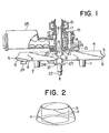
- Fig. 1 is a partial view, in vertical section, of a device according to the present invention, in combination with a device for forming a composite bar;
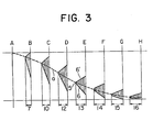
- Fig. 2 is a diagrammatic view of a surface of revolution formed by the movement of the cutter blade edges of a cutter member of the device of Fig. 1, having two spiral arcuate blades;
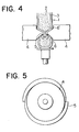
- Fig. 3 is a diagrammatic view of the changing cross-sectional shape of a cutter blade of the device;
- Fig. 4 is a view illustrating the operation of the cutters of the device; and
- Fig. 5 is a plan view of a cutter of the device, having two spiral arcuate blades.
- In Fig. 1, a pair of similar
circular cutters 4 each with top and bottom planar surfaces and a peripheral side surface, are attached to respective shafts 7 which are rotatable about their respective axes disposed vertically and parallel to each other. Thecutters 4 are arranged at the same level, with a predetermined gap therebetween. - Each
cutter 4 is formed with cutting means on its peripheral side surface, which means consists of two spiralarcuate blades 5 extending along the said peripheral side surface of the cutter 4 (see Fig. 5) and arranged within equi-anqular ranges so that one of the blades starting at the top of the said peripheral side surface terminates near the bottom of the said surface substantially vertically under the starting point of theother blade 5. The edge of eachblade 5 is blunt throughout its length, as will be seen from Fig. 1. - The radius of a surface of revolution formed by the edges of the blades when the
cutter 4 is rotated about its axis, increases gradually from the top to the bottom, as shown in Fig. 2. The reference letter a in Figs. 2 and 3- shows a helix described by the outermost point of the blade edge. The reference letter b in Fig. 2 shows the above-mentioned surface of revolution. - The
underside 6 of eachblade 5 is a generally flat surface whose inclination gradually changes from nearly vertical at its top to nearly horizontal at its bottom, as will be seen from Fig. 3, which is a diagrammatic view showing the changing cross-sectional shape and position at eight sections (A, B, C, D, E, F, G, H) of acutter blade 5 taken along the axis of thecutter 4. The numerals inscribed at the lower portion of Fig. 3 show approximate ratios comparing the horizontal heights of the blade at the above-mentioned sections. - The upper side 6' of the
blade 5 is preferably shaped to come into contact with a bar 1 only at a region near the blunt edge of theblade 5. - The pair of
cutters 4 are rotated at the same speed and in the same direction so that the spiralarcuate blades 5 are always at the same level where they meet in opposition to each other at the said gap. The bar 1 is continuously fed downwardly toward and into the said gap between therotating cutters 4 with the central axis of the bar 1 being made to coincide with a vertical line passing through the middle of the gap between the cutters. - The bar 1 consists of a sleeve of a covering material 3 surrounding a central core of a
filler material 2. The bar can be formed by a known apparatus, shown in Fig. 1, which does not constitute part of the present invention and is described in detail in U.S. Patent No. 3,615,147. Such apparatus will be briefly described merely with reference to its function of moulding the bar 1.Core material 2 is forced from a supply device (not shown) into a rotary hollow pipe 8 which is rotated by asprocket wheel 16. The pipe 8 imparts rotation to outer surface portions of thecore material 2 while supplying it in a steady stream in the direction ofcutters 4. Covering material 3 is forced from asupply device 25 through aninlet 12 into acylinder 13, and is pushed downward in a tubular shape by ahelical screw 14 which is attached to the exterior of the pipe 8. Then the covering material 3 passes through an annular aperture 11 defined by a nozzle portion 9 of the pipe 8 and a rotary funnel-shaped ring 10 securely attached to thecylinder 13 by afixture 15, andenvelopes core material 2, thus forming a two-layered bar shape. When passing through the aperture 11, the covering material 3 is given a uniform thickness as well as a rotation exactly equal to that of the outer surface portions of thecore material 2, and thus the covering and core materials are forwarded to thecutters 4 as one body. - The above-mentioned
ring 10 is formed so that the inner diameter of the upper end thereof is identical to that of thecylinder 13 and the inner diameter of the lower end thereof is larger than that of the nozzle portion 9, to define said annular aperture as mentioned above. - The
ring 10 is made to rotate by.a gear mechanism comprising agear 20 integral with thering 10, agear 19 meshing with thegear 20, agear 18 attached to an end of a shaft to the other end of which thegear 19 is secured, and agear 17 meshing with thegear 18. Thegear 17 is integrally secured to the pipe 8. - A receiving
dish 21 located under thecutters 4 is adapted to be moved up and down through ashaft 22 which can be operated by a mechanism not shown.Balls 23 completed by thecutters 4 are received by thedish 21 and transferred by pusher means 24 attached to the underside of one of thecutters 4 onto a conveying device such a a belt conveyor (not shown). - Such a discharging mechanism for the completed balls is also generally known and is disclosed fully in U.S. Patents Nos. 3,351,026 and 3,572,259, but the pusher means 24 in the present device has a plurality of pusher arms corresponding to the number of spiral
arcuate blades 5 of thecutter 4. - The manner of separation of balls from the bar will be explained briefly hereinbelow.
- When the bar 1, fed toward the
cutters 4, comes into contact with two of the spiralarcuate blades 5 on the respective cutters, the bar is subjected to a composite rolling and squeezing motion by the pair of opposing blades, whose spiral pattern is such as to reduce the separating gap between the two cutters to a predetermined dimension while descending, so that the bar is gradually constricted inwardly while being twisted. As a result, a top half of the ball is formed, while the upper sides 6' of the blades act to form the bottom half of the subsequent ball. The leading portion of the bar is separated from the rest when the blades reach their lowermost position. Next, the other pair ofopposing blades 5 adjacent to the first-mentioned pair are brought into contact with the bar to form a top half of the subsequent ball in the same manner as stated above. This is different from the operation of the cutting means of the aforementioned known device having a single spiral blade in each cutter, in that in the known device the single spiral blade itself functions to form the top half of the subsequent ball in cooperation with its opposing single spiral blade. - While the present invention has been described in connection with a preferred embodiment, it is to be understood that various modifications and improvements can be made therein without departing from the scope of the invention as disclosed in the appended claims. For instance, the number of spiral
arcuate blades 5 on each cutter may be more than two. Furthermore, despite the emphasis herein on the formation of balls formed of a covering material surrounding a central core of another material, it should be understood that a device according to the invention may also be used to form balls of a single plastic material from a homogeneous bar of such material.
Claims (4)
Applications Claiming Priority (2)
| Application Number | Priority Date | Filing Date | Title |
|---|---|---|---|
| JP1983083932U JPS6024157Y2 (en) | 1983-06-03 | 1983-06-03 | Enveloping and cutting device for plastic materials |
| JP83932/83 | 1983-06-03 |
Publications (3)
| Publication Number | Publication Date |
|---|---|
| EP0127715A2 true EP0127715A2 (en) | 1984-12-12 |
| EP0127715A3 EP0127715A3 (en) | 1986-03-19 |
| EP0127715B1 EP0127715B1 (en) | 1989-01-25 |
Family
ID=13816368
Family Applications (1)
| Application Number | Title | Priority Date | Filing Date |
|---|---|---|---|
| EP83306125A Expired EP0127715B1 (en) | 1983-06-03 | 1983-10-10 | Device for forming balls of plastic material |
Country Status (8)
| Country | Link |
|---|---|
| EP (1) | EP0127715B1 (en) |
| JP (1) | JPS6024157Y2 (en) |
| KR (1) | KR860002210Y1 (en) |
| AT (1) | ATE40265T1 (en) |
| CA (1) | CA1224674A (en) |
| DD (1) | DD213826A5 (en) |
| DE (1) | DE3379028D1 (en) |
| PH (1) | PH20859A (en) |
Cited By (10)
| Publication number | Priority date | Publication date | Assignee | Title |
|---|---|---|---|---|
| EP0230368A2 (en) | 1986-01-16 | 1987-07-29 | Rheon Automatic Machinery Co. Ltd. | Forming a spherical body |
| EP0247826A1 (en) * | 1986-05-26 | 1987-12-02 | Rheon Automatic Machinery Co. Ltd. | Apparatus for forming a spherical body |
| EP0247825A1 (en) * | 1986-05-26 | 1987-12-02 | Rheon Automatic Machinery Co. Ltd. | Apparatus for forming a spherical body |
| EP0359393A1 (en) * | 1988-08-12 | 1990-03-21 | Masao Kobayashi | Apparatus for the formation of a shaped food product |
| EP0385570A2 (en) * | 1989-01-30 | 1990-09-05 | Bernard Matthews Plc | Food product manufacture by coextrusion |
| EP0443849A1 (en) * | 1990-02-21 | 1991-08-28 | Rheon Automatic Machinery Co. Ltd. | Marble-pattern filling delivery apparatus |
| CN1044848C (en) * | 1992-01-30 | 1999-09-01 | 高拔公司 | Cutting apparatus for bar shaped plastic food |
| EP1152708A2 (en) * | 1999-01-28 | 2001-11-14 | H.J. Heinz Company | Filled edible product, and system and method for production of a filled edible product |
| CN104443598A (en) * | 2013-09-22 | 2015-03-25 | 翁建建 | Necked-opening bionic mechanical hand and sheltering device |
| CN114073264A (en) * | 2021-11-29 | 2022-02-22 | 朱丽霞 | Fish ball forming equipment for food processing |
Families Citing this family (2)
| Publication number | Priority date | Publication date | Assignee | Title |
|---|---|---|---|---|
| JPH0111036Y2 (en) * | 1985-03-20 | 1989-03-30 | ||
| CN113632816A (en) * | 2021-08-17 | 2021-11-12 | 山东银鹰炊事机械有限公司 | Meatball forming machine |
Citations (3)
| Publication number | Priority date | Publication date | Assignee | Title |
|---|---|---|---|---|
| US3572259A (en) * | 1969-07-08 | 1971-03-23 | Torahiko Hayashi | Apparatus for molding elastic dough materials from bar shapes into spherical shapes |
| US3988085A (en) * | 1975-11-24 | 1976-10-26 | Krchma Ludwig C | Apparatus for forming uniform shaped particles of thermoplastic material |
| US4251201A (en) * | 1978-09-18 | 1981-02-17 | Krysiak Janusz D | Extrusion apparatus |
-
1983
- 1983-06-03 JP JP1983083932U patent/JPS6024157Y2/en not_active Expired
- 1983-10-10 DE DE8383306125T patent/DE3379028D1/en not_active Expired
- 1983-10-10 AT AT83306125T patent/ATE40265T1/en not_active IP Right Cessation
- 1983-10-10 KR KR2019830008660U patent/KR860002210Y1/en not_active IP Right Cessation
- 1983-10-10 DD DD83255544A patent/DD213826A5/en not_active IP Right Cessation
- 1983-10-10 EP EP83306125A patent/EP0127715B1/en not_active Expired
-
1984
- 1984-01-05 PH PH30071A patent/PH20859A/en unknown
- 1984-02-23 CA CA000448085A patent/CA1224674A/en not_active Expired
Patent Citations (3)
| Publication number | Priority date | Publication date | Assignee | Title |
|---|---|---|---|---|
| US3572259A (en) * | 1969-07-08 | 1971-03-23 | Torahiko Hayashi | Apparatus for molding elastic dough materials from bar shapes into spherical shapes |
| US3988085A (en) * | 1975-11-24 | 1976-10-26 | Krchma Ludwig C | Apparatus for forming uniform shaped particles of thermoplastic material |
| US4251201A (en) * | 1978-09-18 | 1981-02-17 | Krysiak Janusz D | Extrusion apparatus |
Cited By (19)
| Publication number | Priority date | Publication date | Assignee | Title |
|---|---|---|---|---|
| EP0230368A2 (en) | 1986-01-16 | 1987-07-29 | Rheon Automatic Machinery Co. Ltd. | Forming a spherical body |
| EP0230368A3 (en) * | 1986-01-16 | 1987-11-19 | Rheon Automatic Machinery Co. Ltd. | Forming a spherical body |
| EP0247826A1 (en) * | 1986-05-26 | 1987-12-02 | Rheon Automatic Machinery Co. Ltd. | Apparatus for forming a spherical body |
| EP0247825A1 (en) * | 1986-05-26 | 1987-12-02 | Rheon Automatic Machinery Co. Ltd. | Apparatus for forming a spherical body |
| EP0359393A1 (en) * | 1988-08-12 | 1990-03-21 | Masao Kobayashi | Apparatus for the formation of a shaped food product |
| US5030078A (en) * | 1989-01-30 | 1991-07-09 | Bernard Matthews Plc | Apparatus for food product manufacture |
| GB2228707B (en) * | 1989-01-30 | 1992-05-20 | Matthews Bernard Plc | Food product manufacture |
| EP0385570A3 (en) * | 1989-01-30 | 1991-03-20 | Bernard Matthews Plc | Food product manufacture by coextrusion |
| EP0385570A2 (en) * | 1989-01-30 | 1990-09-05 | Bernard Matthews Plc | Food product manufacture by coextrusion |
| GB2228707A (en) * | 1989-01-30 | 1990-09-05 | Matthews Bernard Plc | "moulding discrete filled food products". |
| US5100682A (en) * | 1989-01-30 | 1992-03-31 | Bernard Matthews Plc | Food product manufacture |
| AU622267B2 (en) * | 1989-01-30 | 1992-04-02 | Bernard Matthews Plc | Food product manufacture |
| EP0443849A1 (en) * | 1990-02-21 | 1991-08-28 | Rheon Automatic Machinery Co. Ltd. | Marble-pattern filling delivery apparatus |
| CN1044848C (en) * | 1992-01-30 | 1999-09-01 | 高拔公司 | Cutting apparatus for bar shaped plastic food |
| EP1152708A2 (en) * | 1999-01-28 | 2001-11-14 | H.J. Heinz Company | Filled edible product, and system and method for production of a filled edible product |
| EP1152708A4 (en) * | 1999-01-28 | 2002-06-12 | Heinz Co H J | Filled edible product, and system and method for production of a filled edible product |
| CN104443598A (en) * | 2013-09-22 | 2015-03-25 | 翁建建 | Necked-opening bionic mechanical hand and sheltering device |
| CN104443598B (en) * | 2013-09-22 | 2018-03-20 | 翁建建 | A kind of beam mouth bionic mechanical hand and radical occlusion device |
| CN114073264A (en) * | 2021-11-29 | 2022-02-22 | 朱丽霞 | Fish ball forming equipment for food processing |
Also Published As
| Publication number | Publication date |
|---|---|
| KR860002210Y1 (en) | 1986-09-13 |
| DD213826A5 (en) | 1984-09-26 |
| CA1224674A (en) | 1987-07-28 |
| JPS59191185U (en) | 1984-12-18 |
| PH20859A (en) | 1987-05-19 |
| EP0127715B1 (en) | 1989-01-25 |
| JPS6024157Y2 (en) | 1985-07-18 |
| ATE40265T1 (en) | 1989-02-15 |
| KR850000313U (en) | 1985-02-27 |
| EP0127715A3 (en) | 1986-03-19 |
| DE3379028D1 (en) | 1989-03-02 |
Similar Documents
| Publication | Publication Date | Title |
|---|---|---|
| EP0127715B1 (en) | Device for forming balls of plastic material | |
| US3572259A (en) | Apparatus for molding elastic dough materials from bar shapes into spherical shapes | |
| US4416910A (en) | Method of continuously manufacturing multi-layered dough materials | |
| US4445835A (en) | Method and apparatus for marbleizing an extruded dough | |
| US4266920A (en) | Apparatus for continuously manufacturing multi-layered dough materials | |
| US3139129A (en) | Method of slicing a food product | |
| US4434526A (en) | Device for separating and processing the gizzards of slaughtered poultry | |
| CN107921651B (en) | System for cutting helical bars | |
| US4941402A (en) | Apparatus for encapsulating filler with dough | |
| CN1027219C (en) | Kneading mechanism of steam stuffed bun shaping machine | |
| CA1234317A (en) | Apparatus and method for continuously producing filled dough pieces | |
| US4589833A (en) | Device for forming balls of plastic material | |
| EP0289220A2 (en) | Rotary slicing machine | |
| TWI700039B (en) | A sesame cracker machine | |
| CN2203038Y (en) | Food rice crust shaper | |
| US5100240A (en) | High-speed continuous mixer for solids and liquids | |
| KR200159343Y1 (en) | Cutter | |
| EP0109987A1 (en) | Apparatus for peeling bulbs | |
| US4420298A (en) | Device for making spatzels | |
| US4755121A (en) | Machine for producing dumplings or troffiette | |
| EP0340383A1 (en) | Sheeting apparatus | |
| KR880001471B1 (en) | Mashine for wrapping bean jam | |
| CN112936384B (en) | Filling slitting and injecting device | |
| CN112790206B (en) | Stuffing slitting and injecting method | |
| US20050220954A1 (en) | Process and system for making shaped snack products |
Legal Events
| Date | Code | Title | Description |
|---|---|---|---|
| PUAI | Public reference made under article 153(3) epc to a published international application that has entered the european phase |
Free format text: ORIGINAL CODE: 0009012 |
|
| AK | Designated contracting states |
Designated state(s): AT BE CH DE FR GB IT LI LU NL SE |
|
| PUAL | Search report despatched |
Free format text: ORIGINAL CODE: 0009013 |
|
| AK | Designated contracting states |
Kind code of ref document: A3 Designated state(s): AT BE CH DE FR GB IT LI LU NL SE |
|
| 17P | Request for examination filed |
Effective date: 19860628 |
|
| 17Q | First examination report despatched |
Effective date: 19870821 |
|
| GRAA | (expected) grant |
Free format text: ORIGINAL CODE: 0009210 |
|
| ITF | It: translation for a ep patent filed |
Owner name: SOCIETA' ITALIANA BREVETTI S.P.A. |
|
| AK | Designated contracting states |
Kind code of ref document: B1 Designated state(s): AT BE CH DE FR GB IT LI LU NL SE |
|
| REF | Corresponds to: |
Ref document number: 40265 Country of ref document: AT Date of ref document: 19890215 Kind code of ref document: T |
|
| REF | Corresponds to: |
Ref document number: 3379028 Country of ref document: DE Date of ref document: 19890302 |
|
| ET | Fr: translation filed | ||
| PLBE | No opposition filed within time limit |
Free format text: ORIGINAL CODE: 0009261 |
|
| STAA | Information on the status of an ep patent application or granted ep patent |
Free format text: STATUS: NO OPPOSITION FILED WITHIN TIME LIMIT |
|
| 26N | No opposition filed | ||
| ITTA | It: last paid annual fee | ||
| EPTA | Lu: last paid annual fee | ||
| EAL | Se: european patent in force in sweden |
Ref document number: 83306125.2 |
|
| PGFP | Annual fee paid to national office [announced via postgrant information from national office to epo] |
Ref country code: SE Payment date: 19981006 Year of fee payment: 16 |
|
| PGFP | Annual fee paid to national office [announced via postgrant information from national office to epo] |
Ref country code: FR Payment date: 19981009 Year of fee payment: 16 |
|
| PGFP | Annual fee paid to national office [announced via postgrant information from national office to epo] |
Ref country code: AT Payment date: 19981014 Year of fee payment: 16 |
|
| PGFP | Annual fee paid to national office [announced via postgrant information from national office to epo] |
Ref country code: GB Payment date: 19981016 Year of fee payment: 16 Ref country code: DE Payment date: 19981016 Year of fee payment: 16 |
|
| PGFP | Annual fee paid to national office [announced via postgrant information from national office to epo] |
Ref country code: LU Payment date: 19981020 Year of fee payment: 16 |
|
| PGFP | Annual fee paid to national office [announced via postgrant information from national office to epo] |
Ref country code: CH Payment date: 19981022 Year of fee payment: 16 |
|
| PGFP | Annual fee paid to national office [announced via postgrant information from national office to epo] |
Ref country code: NL Payment date: 19981028 Year of fee payment: 16 |
|
| PGFP | Annual fee paid to national office [announced via postgrant information from national office to epo] |
Ref country code: BE Payment date: 19981216 Year of fee payment: 16 |
|
| PG25 | Lapsed in a contracting state [announced via postgrant information from national office to epo] |
Ref country code: LU Free format text: LAPSE BECAUSE OF NON-PAYMENT OF DUE FEES Effective date: 19991010 Ref country code: GB Free format text: LAPSE BECAUSE OF NON-PAYMENT OF DUE FEES Effective date: 19991010 Ref country code: AT Free format text: LAPSE BECAUSE OF NON-PAYMENT OF DUE FEES Effective date: 19991010 |
|
| PG25 | Lapsed in a contracting state [announced via postgrant information from national office to epo] |
Ref country code: SE Free format text: THE PATENT HAS BEEN ANNULLED BY A DECISION OF A NATIONAL AUTHORITY Effective date: 19991030 |
|
| PG25 | Lapsed in a contracting state [announced via postgrant information from national office to epo] |
Ref country code: LI Free format text: LAPSE BECAUSE OF NON-PAYMENT OF DUE FEES Effective date: 19991031 Ref country code: CH Free format text: LAPSE BECAUSE OF NON-PAYMENT OF DUE FEES Effective date: 19991031 Ref country code: BE Free format text: LAPSE BECAUSE OF NON-PAYMENT OF DUE FEES Effective date: 19991031 |
|
| BERE | Be: lapsed |
Owner name: RHEON AUTOMATIC MACHINERY CO. LTD Effective date: 19991031 |
|
| PG25 | Lapsed in a contracting state [announced via postgrant information from national office to epo] |
Ref country code: NL Free format text: LAPSE BECAUSE OF NON-PAYMENT OF DUE FEES Effective date: 20000501 |
|
| GBPC | Gb: european patent ceased through non-payment of renewal fee |
Effective date: 19991010 |
|
| REG | Reference to a national code |
Ref country code: CH Ref legal event code: PL |
|
| EUG | Se: european patent has lapsed |
Ref document number: 83306125.2 |
|
| PG25 | Lapsed in a contracting state [announced via postgrant information from national office to epo] |
Ref country code: FR Free format text: LAPSE BECAUSE OF NON-PAYMENT OF DUE FEES Effective date: 20000630 |
|
| NLV4 | Nl: lapsed or anulled due to non-payment of the annual fee |
Effective date: 20000501 |
|
| PG25 | Lapsed in a contracting state [announced via postgrant information from national office to epo] |
Ref country code: DE Free format text: LAPSE BECAUSE OF NON-PAYMENT OF DUE FEES Effective date: 20000801 |
|
| REG | Reference to a national code |
Ref country code: FR Ref legal event code: ST |