EP0127781A2 - Self-venting, non-coring needle assembly - Google Patents
Self-venting, non-coring needle assembly Download PDFInfo
- Publication number
- EP0127781A2 EP0127781A2 EP19840105007 EP84105007A EP0127781A2 EP 0127781 A2 EP0127781 A2 EP 0127781A2 EP 19840105007 EP19840105007 EP 19840105007 EP 84105007 A EP84105007 A EP 84105007A EP 0127781 A2 EP0127781 A2 EP 0127781A2
- Authority
- EP
- European Patent Office
- Prior art keywords
- cannula
- needle assembly
- sleeve member
- sleeve
- hub
- Prior art date
- Legal status (The legal status is an assumption and is not a legal conclusion. Google has not performed a legal analysis and makes no representation as to the accuracy of the status listed.)
- Granted
Links
- 238000013022 venting Methods 0.000 title claims abstract description 39
- 239000012530 fluid Substances 0.000 claims abstract description 35
- 239000007788 liquid Substances 0.000 claims abstract description 34
- 238000012546 transfer Methods 0.000 claims abstract description 28
- 238000004891 communication Methods 0.000 claims abstract description 18
- 239000000463 material Substances 0.000 claims description 12
- 239000012815 thermoplastic material Substances 0.000 claims description 4
- 229910001220 stainless steel Inorganic materials 0.000 claims description 3
- 239000010935 stainless steel Substances 0.000 claims description 3
- 230000014759 maintenance of location Effects 0.000 claims 2
- 239000007789 gas Substances 0.000 abstract description 4
- 239000003814 drug Substances 0.000 description 16
- 229940079593 drug Drugs 0.000 description 16
- 239000011162 core material Substances 0.000 description 14
- 230000035515 penetration Effects 0.000 description 11
- 239000004593 Epoxy Substances 0.000 description 6
- -1 polypropylene Polymers 0.000 description 6
- XLYOFNOQVPJJNP-UHFFFAOYSA-N water Chemical compound O XLYOFNOQVPJJNP-UHFFFAOYSA-N 0.000 description 5
- 239000004698 Polyethylene Substances 0.000 description 3
- 230000036512 infertility Effects 0.000 description 3
- 239000000314 lubricant Substances 0.000 description 3
- 229920000573 polyethylene Polymers 0.000 description 3
- 239000008223 sterile water Substances 0.000 description 3
- 239000004743 Polypropylene Substances 0.000 description 2
- 239000008280 blood Substances 0.000 description 2
- 210000004369 blood Anatomy 0.000 description 2
- 238000010276 construction Methods 0.000 description 2
- 239000011521 glass Substances 0.000 description 2
- 231100000206 health hazard Toxicity 0.000 description 2
- 229920001155 polypropylene Polymers 0.000 description 2
- 210000003462 vein Anatomy 0.000 description 2
- 230000004913 activation Effects 0.000 description 1
- 239000000853 adhesive Substances 0.000 description 1
- 230000001070 adhesive effect Effects 0.000 description 1
- 239000003708 ampul Substances 0.000 description 1
- 238000011109 contamination Methods 0.000 description 1
- 229920001971 elastomer Polymers 0.000 description 1
- 239000003822 epoxy resin Substances 0.000 description 1
- 238000009472 formulation Methods 0.000 description 1
- LNEPOXFFQSENCJ-UHFFFAOYSA-N haloperidol Chemical compound C1CC(O)(C=2C=CC(Cl)=CC=2)CCN1CCCC(=O)C1=CC=C(F)C=C1 LNEPOXFFQSENCJ-UHFFFAOYSA-N 0.000 description 1
- 230000006872 improvement Effects 0.000 description 1
- 238000002347 injection Methods 0.000 description 1
- 239000007924 injection Substances 0.000 description 1
- 238000003780 insertion Methods 0.000 description 1
- 230000037431 insertion Effects 0.000 description 1
- 238000001990 intravenous administration Methods 0.000 description 1
- 229920002529 medical grade silicone Polymers 0.000 description 1
- 238000000034 method Methods 0.000 description 1
- 239000000203 mixture Substances 0.000 description 1
- 239000004033 plastic Substances 0.000 description 1
- 229920003023 plastic Polymers 0.000 description 1
- 229920000647 polyepoxide Polymers 0.000 description 1
- 229920001343 polytetrafluoroethylene Polymers 0.000 description 1
- 239000004810 polytetrafluoroethylene Substances 0.000 description 1
- 230000008569 process Effects 0.000 description 1
- 238000012545 processing Methods 0.000 description 1
- 230000000284 resting effect Effects 0.000 description 1
- 230000001954 sterilising effect Effects 0.000 description 1
- 238000004659 sterilization and disinfection Methods 0.000 description 1
- 229920001169 thermoplastic Polymers 0.000 description 1
- 239000004416 thermosoftening plastic Substances 0.000 description 1
Images


Classifications
-
- A—HUMAN NECESSITIES
- A61—MEDICAL OR VETERINARY SCIENCE; HYGIENE
- A61J—CONTAINERS SPECIALLY ADAPTED FOR MEDICAL OR PHARMACEUTICAL PURPOSES; DEVICES OR METHODS SPECIALLY ADAPTED FOR BRINGING PHARMACEUTICAL PRODUCTS INTO PARTICULAR PHYSICAL OR ADMINISTERING FORMS; DEVICES FOR ADMINISTERING FOOD OR MEDICINES ORALLY; BABY COMFORTERS; DEVICES FOR RECEIVING SPITTLE
- A61J1/00—Containers specially adapted for medical or pharmaceutical purposes
- A61J1/14—Details; Accessories therefor
- A61J1/20—Arrangements for transferring or mixing fluids, e.g. from vial to syringe
- A61J1/2096—Combination of a vial and a syringe for transferring or mixing their contents
-
- A—HUMAN NECESSITIES
- A61—MEDICAL OR VETERINARY SCIENCE; HYGIENE
- A61M—DEVICES FOR INTRODUCING MEDIA INTO, OR ONTO, THE BODY; DEVICES FOR TRANSDUCING BODY MEDIA OR FOR TAKING MEDIA FROM THE BODY; DEVICES FOR PRODUCING OR ENDING SLEEP OR STUPOR
- A61M5/00—Devices for bringing media into the body in a subcutaneous, intra-vascular or intramuscular way; Accessories therefor, e.g. filling or cleaning devices, arm-rests
- A61M5/14—Infusion devices, e.g. infusing by gravity; Blood infusion; Accessories therefor
- A61M5/162—Needle sets, i.e. connections by puncture between reservoir and tube ; Connections between reservoir and tube
-
- A—HUMAN NECESSITIES
- A61—MEDICAL OR VETERINARY SCIENCE; HYGIENE
- A61J—CONTAINERS SPECIALLY ADAPTED FOR MEDICAL OR PHARMACEUTICAL PURPOSES; DEVICES OR METHODS SPECIALLY ADAPTED FOR BRINGING PHARMACEUTICAL PRODUCTS INTO PARTICULAR PHYSICAL OR ADMINISTERING FORMS; DEVICES FOR ADMINISTERING FOOD OR MEDICINES ORALLY; BABY COMFORTERS; DEVICES FOR RECEIVING SPITTLE
- A61J1/00—Containers specially adapted for medical or pharmaceutical purposes
- A61J1/14—Details; Accessories therefor
- A61J1/20—Arrangements for transferring or mixing fluids, e.g. from vial to syringe
- A61J1/2003—Accessories used in combination with means for transfer or mixing of fluids, e.g. for activating fluid flow, separating fluids, filtering fluid or venting
- A61J1/2006—Piercing means
- A61J1/201—Piercing means having one piercing end
-
- A—HUMAN NECESSITIES
- A61—MEDICAL OR VETERINARY SCIENCE; HYGIENE
- A61J—CONTAINERS SPECIALLY ADAPTED FOR MEDICAL OR PHARMACEUTICAL PURPOSES; DEVICES OR METHODS SPECIALLY ADAPTED FOR BRINGING PHARMACEUTICAL PRODUCTS INTO PARTICULAR PHYSICAL OR ADMINISTERING FORMS; DEVICES FOR ADMINISTERING FOOD OR MEDICINES ORALLY; BABY COMFORTERS; DEVICES FOR RECEIVING SPITTLE
- A61J1/00—Containers specially adapted for medical or pharmaceutical purposes
- A61J1/14—Details; Accessories therefor
- A61J1/20—Arrangements for transferring or mixing fluids, e.g. from vial to syringe
- A61J1/2003—Accessories used in combination with means for transfer or mixing of fluids, e.g. for activating fluid flow, separating fluids, filtering fluid or venting
- A61J1/2068—Venting means
- A61J1/2075—Venting means for external venting
-
- A—HUMAN NECESSITIES
- A61—MEDICAL OR VETERINARY SCIENCE; HYGIENE
- A61J—CONTAINERS SPECIALLY ADAPTED FOR MEDICAL OR PHARMACEUTICAL PURPOSES; DEVICES OR METHODS SPECIALLY ADAPTED FOR BRINGING PHARMACEUTICAL PRODUCTS INTO PARTICULAR PHYSICAL OR ADMINISTERING FORMS; DEVICES FOR ADMINISTERING FOOD OR MEDICINES ORALLY; BABY COMFORTERS; DEVICES FOR RECEIVING SPITTLE
- A61J2200/00—General characteristics or adaptations
- A61J2200/10—Coring prevention means, e.g. for plug or septum piecing members
-
- A—HUMAN NECESSITIES
- A61—MEDICAL OR VETERINARY SCIENCE; HYGIENE
- A61M—DEVICES FOR INTRODUCING MEDIA INTO, OR ONTO, THE BODY; DEVICES FOR TRANSDUCING BODY MEDIA OR FOR TAKING MEDIA FROM THE BODY; DEVICES FOR PRODUCING OR ENDING SLEEP OR STUPOR
- A61M5/00—Devices for bringing media into the body in a subcutaneous, intra-vascular or intramuscular way; Accessories therefor, e.g. filling or cleaning devices, arm-rests
- A61M5/14—Infusion devices, e.g. infusing by gravity; Blood infusion; Accessories therefor
- A61M5/162—Needle sets, i.e. connections by puncture between reservoir and tube ; Connections between reservoir and tube
- A61M2005/1623—Details of air intake
-
- A—HUMAN NECESSITIES
- A61—MEDICAL OR VETERINARY SCIENCE; HYGIENE
- A61M—DEVICES FOR INTRODUCING MEDIA INTO, OR ONTO, THE BODY; DEVICES FOR TRANSDUCING BODY MEDIA OR FOR TAKING MEDIA FROM THE BODY; DEVICES FOR PRODUCING OR ENDING SLEEP OR STUPOR
- A61M2205/00—General characteristics of the apparatus
- A61M2205/19—Constructional features of carpules, syringes or blisters
- A61M2205/192—Avoiding coring, e.g. preventing formation of particles during puncture
- A61M2205/195—Avoiding coring, e.g. preventing formation of particles during puncture by the needle tip shape
Definitions
- Non-coring puncture devices without venting capability are also available, but are of limited use in transferring liquid to or from a vial with a pierceable stopper unless two or more of these devices are used.
- Both Ogle (U.S. Pat. No. 3,941,171) and Brignola (U.S. Pat. No. 4,296,786) teach fluid transfer devices wherein most embodiments include a central body portion with large spike like projections extending outwardly from each side of the central portion.
- the spikes contain a pair of common longitudinally staggered parallel passages extending from the tip of one spike to the tip of the other. Since the passageways terminate at the end surface of the spikes, these devices have the potential of producing-up to four cores with each vial to vial transfer. Also, the large spike size required by parallel passageways increases the potential for stopper damage and requires higher forces for penetration into the stopper. This type of device is only suitable for vial to vial transfer.
- Murphy U.S. Pat. No. 2,541,272 teaches a needle for filling and exhausting ampules and, like Stawski, the Murphy needle has two hubs and one point for potential generation of cores.
- Murphy shows an outer sleeve which is tapered toward and anchored to the inner needle at the end of sleeve furthest from the hubs.
- the sleeve contains venting ports in its side and in its hub.
- the external venting groove would appear to present a potential problem in that rotation of the spike along its longitudinal axis, while it is inserted in a flexible stopper, may cause parts of the stopper, along the puncture hole, to enter the groove and reduce or terminate venting capacity.
- the second cannula is non-coring and has a compressed end which is cut off at an angle to the longitudinal axis of the cannula and an aperture in its side which communicates with the lumen therein.
- the second cannula does not have any venting structure and, because of its use, must not allow venting to the atmosphere which would reduce the vacuum forces needed to draw the blood from the patient.
- the flat portion terminates in a straight edge lying at an angle to the longitudinal axis of the cannula.
- An aperture which is in fluid communication with the lumen, is positioned in the side wall of the cannula adjacent to the distal end.
- circularly shaped sleeve member surrounding the cannula and slidably engaged thereon.
- the sleeve member is shorter in length than the distance between the aperture and the forward end of the hub.
- the inside diameter of the sleeve is larger than the outside diameter of the cannula to allow gas to pass therebetween and smaller than the flat portion along its major axis so that the sleeve is prevented from sliding off the distal end of the cannula.
- the inside diameter of the sleeve member is smaller than the hub so that the sleeve is prevented from sliding off the cannula at its proximal end.
- the present invention provides a simple straight forward self-venting, non-coring needle assembly which allows transfer of liquid to and from a vial with a pierceable stopper.
- the flat portion of the closed distal end of the cannula provides a non-coring stopper piercing point which also minimizes penetration forces and stopper damage during insertion of the cannula into the stopper.
- the sleeve member also contributes to the non-coring aspect of the present invention by entering the same hole in the stopper as made by the cannula. During use, gases are vented by passing between the outside of cannula and the inside dimension of the sleeve.
- the present invention is also operable without the use of external apparatus which is not part of the fluid path.
- a closed distal end 30 of the cannula includes a compressed planar or flat portion 31 which is substantially parallel to a longitudinal axis 34 of the cannula and larger along its major dimension than outside diameter 33 of the cannula. Further, the planar portion terminates at a straight edge 32 lying at an angle to longitudinal axis 34. It is preferred that lesser included angle X between edge 32 and longitudinal axis 34 be between about twenty to sixty degrees with the preferred embodiment shown at thirty degrees. It is also preferred that flat portion 31 include a tapered portion 35 which is tapered toward straight edge 32 in a razor-like fashion.
- the inside diameter of sleeve 37 is smaller than flat portion 31, when measured along the major axis of the flat portion, so that the sleeve is prevented from sliding off the closed distal end of the cannula.
- the inside diameter of the sleeve is also smaller than at least one portion of the hub, when measured in a direction transverse to the longitudinal axis of the cannula, so that the sleeve is prevented from sliding off the cannula at its proximal end.
- Sleeve member 37 as measured in a direction along the longitudinal axis thereof, should preferably be shorter than the distance between aperture 36 and hub 21 so that sleeve member 37 will not interfere with fluid flow through the aperture. Also, as will later become evident, it is preferred that sleeve member 37 be longer than the thickness of the stopper being pierced by the needle assembly.
- the instant invention prevents pressure build-up by allowing pressurized air, contained within the vial, to exit through the space between outside diameter 33-of cannula 26 and inside diameter 38 of sleeve 37. It is desirable to make the diameters of. the sleeve as small as possible in order to prevent possible coring by the sleeve as it passes through the hole in the stopper made by the cannula and also to prevent damage to the stopper.
- Another possible use of the instant invention is in withdrawing sterile water from a vial with a pierceable stopper into a syringe and then placing smaller quantities of water into each of many smaller vials containing lyophilized medication which requires water for activation. This entire operation can be accomplished with one needle assembly of the present invention rather than, for example, several needles, a valve and tubing.
- thermoplastic materials such as polypropylene and polyethylene are preferred. It is preferred that the cannula and sleeve be constructed of a medical grade stainless steel except where the sleeve contains spaced projections extending radially inwardly from the inside diameter. With the latter sleeve construction, thermoplastic materials such as polypropylene, polytetrafluoroethylene and polyethylene are preferred.
- a wide variety of medical grade epoxy resins is commercially available. The choice of epoxy formulation is dictated by the materials and processing conditions chosen for the needle assembly.
- thermoplastic materials such as ABS, polyproplylene and polyethylene are preferred. It may also be desirable to apply a medical grade lubricant, such as medical grade silicon lubricant, to the outside of the cannula to reduce the force required for cannula penetration of the stopper. It is preferred that all elements of the self-venting, non-coring needle assembly should be sterile when used. Accordingly, materials should be selected for compatability with the sterilization process being used.
Abstract
Description
-
- 1. Field of the Invention. The present invention relates to a needle assembly and more particularily concerns a self-venting, non-coring needle assembly for the transfer of liquid to or from a container having a needle penetrable stopper thereon.
- 2. Description of the Prior Art. Liquid. medication, for injection and intravenous applications, is commonly available in rigid containers having a closure with an elastomeric needle penetrable stopper. Frequently the amount of liquid medication in these containers is in excess of the amount required for each individual dose. Accordingly, it is the task of a hospital pharmacy, for example, to transfer the liquid medication from the larger container to smaller containers, also with needle penetrable stoppers, such as I.V. bottles or to other storage or delivery devices such as syringes. This type of transfer is also required where the medication has a short shelf life and must be mixed just prior to use, for example using a syringe for adding sterile water to a vial containing lyophilized medication. Since sterility of the medication is desired, the vial to vial, syringe to vial, or vial to syringe transfer is usually performed in a laminar flow hood. Transfer of liquid medication to and from these vials requires not only piercing the stopper to provide a path for the medication but also piercing the stopper to provide a path for air to escape or enter the vial so that the medication will flow freely.
- Prior art devices for the aforementioned transfer of liquids are fraught with problems. For example, a hollow pointed shaft or needle for piercing a vial stopper, as will be explained in greater detail hereinafter, may cause coring. Coring results from the needle not only piercing the stopper but also cutting a core of stopper material with the relatively sharp edges found at the intersection of the inside diameter of the needle and the surface at the end of the needle. These cores represent a potential health hazard if they pass along with the liquid medication into the patient's body. Also, if the cores are large enough or if there are many of them, the stopper may not retain enough material to effectively seal the vial in order to prevent leakage or to protect sterility. In addition, if the device used to puncture the stopper is too large, it may damage the stopper, even in the absence of any coring, by ripping or tearing the stopper so that it no longer effectively seals the vial. Non-coring puncture devices without venting capability are also available, but are of limited use in transferring liquid to or from a vial with a pierceable stopper unless two or more of these devices are used.
- Both Ogle (U.S. Pat. No. 3,941,171) and Brignola (U.S. Pat. No. 4,296,786) teach fluid transfer devices wherein most embodiments include a central body portion with large spike like projections extending outwardly from each side of the central portion. The spikes contain a pair of common longitudinally staggered parallel passages extending from the tip of one spike to the tip of the other. Since the passageways terminate at the end surface of the spikes, these devices have the potential of producing-up to four cores with each vial to vial transfer. Also, the large spike size required by parallel passageways increases the potential for stopper damage and requires higher forces for penetration into the stopper. This type of device is only suitable for vial to vial transfer.
- Similar to the above described inventions, Murrish (U.S. Pat. No. 2,973,758) teaches a device with a central member with two spaced needles projecting from one side thereof. One of these needles passes through the member and projects from the other side. The other needle vents to the other side of the member but does not project outwardly therefrom. Here again, for piercing and venting, two separate punctures are required, with two chances for producing cores. Also, none of the above-mentioned patents teaches a device which can be used in conjunction with a syringe or tubing with luer fittings.
- Stawski (U.S. Pat. No. 3,608,550) teaches a transfer needle assembly for use in transferring liquid medication from a vial with a pierceable stopper to a plurality of syringes. Stawski shows a device with two cannulae, each having its own hub. The larger diameter cannula is used to pierce the rubber stopper and then the smaller diameter cannula slides through the larger cannula to contact the liquid in the vial. Venting takes place between the outside diameter of the smaller cannula and the inside diameter of the larger cannula. The Stawski transfer needle offers an improvement over the above-mentioned devices in that there -is only one puncture which can potentially produce a core from the stopper. However, the Stawski device is primarily intended for the limited use of filling syringes and is more time-wise efficient when used with external apparatus which positions the transfer. needle, but is not part of the fluid path. This external apparatus is taught by Stawski in U.S. Pat. No. 3,602,272.
- Murphy (U.S. Pat. No. 2,541,272) teaches a needle for filling and exhausting ampules and, like Stawski, the Murphy needle has two hubs and one point for potential generation of cores. Murphy shows an outer sleeve which is tapered toward and anchored to the inner needle at the end of sleeve furthest from the hubs. The sleeve contains venting ports in its side and in its hub.
- Choksi et al. (U.S. Pat. No. 4,058,121) teach a thermoplastic needle for injecting sterile liquid into a vial. This needle is in the shape of a plastic spike with an external vent groove running along the length of the spike. Liquid leaves the spike through two side ports therein. Choksi et al. eliminate coring by providing a pointed tip, however, the side ports, which are formed in the tapered portion of the tip, may contribute to tearing small pieces of the stopper loose as the spike moves through the stopper. Also, the apparently large cross-section can contribute to stopper damage. The external venting groove would appear to present a potential problem in that rotation of the spike along its longitudinal axis, while it is inserted in a flexible stopper, may cause parts of the stopper, along the puncture hole, to enter the groove and reduce or terminate venting capacity.
- Also known is the VACUTAINER brand Multiple Sample Needle as shown in a products catalog of Becton, Dickinson and Company. This needle has two opposed cannula communicating with a central external screw thread hub. The hub is intended to be screwed into a cylindrical holder after which the first cannula, which projects outwardly from the hub, is inserted in a patient's vein. Then, an evacuated glass tube with a pierceable stopper is forceably slid into the cylindrical holder until the second cannula, which projects into the holder, pierces and passes through the evacuated tube stopper. At this point there is fluid communication between the patient's vein and the evacuated glass tube, and blood is drawn from the patient into the tube by the vacuum forces therein created. The second cannula is non-coring and has a compressed end which is cut off at an angle to the longitudinal axis of the cannula and an aperture in its side which communicates with the lumen therein. The second cannula does not have any venting structure and, because of its use, must not allow venting to the atmosphere which would reduce the vacuum forces needed to draw the blood from the patient.
- The transfer of liquid to or from a container or vial with closure having an elastomeric needle penetrable stopper has been addressed by the prior art. However, there is still a need for a simple, straight-forward, reliable, easily fabricated self-venting, non-coring needle assembly which allows transfer of liquid to and from a vial with a pierceable stopper while incurring minimal stopper damage and requiring minimal penetration forces. It is also- desirable that the needle assembly be operable without the use of an external apparatus which is not part of the fluid-path.
- The self-venting, non-coring needle assembly of the present invention comprises a hub having a forward end, a rearward end adapted to engage external fluid transfer apparatus and a passageway therethrough. A hollow shaft extends outwardly from the forward end of the hub. This shaft has a lumen which is in fluid communication with the hub passageway and a closed distal end. An aperture in the side of the shaft adjacent to the distal end is in fluid communication with the lumen. A sleeve is slidably maintained on the shaft. Venting means is provided for allowing gas to pass between the outside of the shaft and the inside of the sleeve.
- In accordance with another embodiment of the present invention, a self-venting, non-coring needle assembly for the transfer of liquid to or from a container having a needle penetrable stopper thereon includes a rigid hub having a forward end, a rearward end adapted to engage external fluid transfer apparatus and a passageway therethrough. A cannula extends outwardly from the forward end of the housing and terminates in a closed distal end. The cannula has a lumen which is in fluid communication with the passageway of the hub. This cannula also contains a flat portion at its distal end which is substantially parallel to the longitudinal axis of the cannula and is larger along its major dimension than the outside diameter of the cannula. Also, the flat portion terminates in a straight edge lying at an angle to the longitudinal axis of the cannula. An aperture, which is in fluid communication with the lumen, is positioned in the side wall of the cannula adjacent to the distal end. Also included is circularly shaped sleeve member surrounding the cannula and slidably engaged thereon. The sleeve member is shorter in length than the distance between the aperture and the forward end of the hub. The inside diameter of the sleeve is larger than the outside diameter of the cannula to allow gas to pass therebetween and smaller than the flat portion along its major axis so that the sleeve is prevented from sliding off the distal end of the cannula. Also, the inside diameter of the sleeve member is smaller than the hub so that the sleeve is prevented from sliding off the cannula at its proximal end.
- In accordance with the principles of the present invention, a number of advantages and objectives are attained. Primarily, the present invention provides a simple straight forward self-venting, non-coring needle assembly which allows transfer of liquid to and from a vial with a pierceable stopper. The flat portion of the closed distal end of the cannula provides a non-coring stopper piercing point which also minimizes penetration forces and stopper damage during insertion of the cannula into the stopper. The sleeve member also contributes to the non-coring aspect of the present invention by entering the same hole in the stopper as made by the cannula. During use, gases are vented by passing between the outside of cannula and the inside dimension of the sleeve. The present invention is also operable without the use of external apparatus which is not part of the fluid path.
-
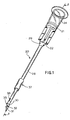
- Fig. 1 is an enlarged perspective view of the preferred self-venting, non-coring needle assembly of the present invention;
- Fig. 2 is a cross-sectional view of the self-venting, non-coring needle assembly of Fig. 1 taken along line 2-2;
- Fig. 3 is a partial enlarged side elevation view of the distal end of the cannula of the preferred self-venting, non-coring needle assembly;
- Fig. 4 is a cross-sectional view of the cannula of Fig. 3 taken along line 4-4;
- Fig. 5 is an enlarged partial side elevation view of a known and used needle shown in relative proximity to a partial enlarged cross-sectional side elevation view of a pierceable vial stopper;
- Fig. 6 is a cross-sectional view of the needle of Fig. 5 taken along line 6-6 as the needle initially penetrates a vial stopper;
- Fig. 7 is a cross-sectional view of the needle of Fig. 5 taken along line 7-7 as the needle further penetrates a vial stopper;
- Fig. 8 is a cross-sectional view of the needle of Fig. 5 taken along line 8-8 as the needle still further penetrates a vial stopper;
- Fig. 9 is a cross-sectional view of the needle of Fig. 5 taken along line 9-9 as the needle still further penetrates a vial stopper;
- Fig. 10 is an enlarged partial side elevation view of the cannula of the preferred self-venting, non-coring needle assembly;
- Fig. 11 is a cross-sectional view of the cannula of Fig. 10 taken along line 11-11 as the cannula penetrates a vial stopper;
- Fig. 12 is an enlarged partial side elevation view of the cannula of another embodiment of the self-venting, non-coring needle assembly;
- Fig. 13 is a cross-sectional view of the cannula of Fig. 12 taken along line 13-13 as the cannula penetrates a vial stopper;
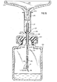
- Fig. 14 is a side elevation view of the preferred self-venting, non-coring needle assembly being used with a hypodermic syringe to fill a liquid container having a needle penetrable stopper thereon;
- Fig. 15 is an enlarged cross-sectional view of the syringe, needle assembly and vial of Fig. 14;
- Fig. 16 is an enlarged partial side elevation view of an alternative embodiment of the present self-venting, non-coring needle assembly;
- Fig. 17 is a cross-sectional view of the self-venting, non-coring needle assembly of Fig. 16 taken along line 17-17;
- Fig. 18 is an enlarged partial perspective view of another alternative embodiment of the self-venting, non-coring needle assembly; and
- Fig. 19 is a cross-sectional view of the self-venting, non-coring needle assembly of Fig. 18 taken along line 19-19.
- While this invention is satisfied by embodiments in many different forms, there is shown in the drawings and will herein be described in detail preferred embodiments of the invention with the understanding that the present disclosure is to be considered as exemplary of the principles of the invention and is not intended to limit the invention to the embodiments illustrated. The scope of the invention will be measured by the appended claims and their equivalents.
- Adverting to Figs. 1 through 4, a self-venting,
non-coring needle assembly 20 includes arigid hub 21 having aforward end 22, arearward end 24 and apassageway 25 therethrough. The rearward end is shaped to accept the standard luer tip of a syringe or other apparatus such as a tubing fitting with a tapered luer tip. Acannula 26 having alumen 27 is connected to the hub so that the lumen is in fluid communication with the passageway. In the preferred embodiment, the forward end of the hub contains arecess 28, larger in diameter than the cannula, running along the longitudinal axis of the hub in fluid communication with the passageway. Space between the outside of the cannula and the inside of the recess is filled withepoxy 29 to fixedly contain the cannula within the hub. It will be apparent to one skilled in the art that numerous constructions can be used to join a cannula and a hub and that the arrangement described above is exemplary of these many possibilities. Also, it is within the purview of this invention to include a one-piece needle and hub assembly. - For descriptive purposes, locations indicated as "distal" are further from the user than locations on the same component indicated as "proximal." A closed
distal end 30 of the cannula includes a compressed planar orflat portion 31 which is substantially parallel to alongitudinal axis 34 of the cannula and larger along its major dimension thanoutside diameter 33 of the cannula. Further, the planar portion terminates at astraight edge 32 lying at an angle tolongitudinal axis 34. It is preferred that lesser included angle X betweenedge 32 andlongitudinal axis 34 be between about twenty to sixty degrees with the preferred embodiment shown at thirty degrees. It is also preferred thatflat portion 31 include a taperedportion 35 which is tapered towardstraight edge 32 in a razor-like fashion. -
Cannula 26 also includes anaperture 36 in the side wall thereof adjacent to closeddistal end 30. This aperture is in fluid communication withlumen 27. In the preferred embodiment,aperture 36 is positioned below and substantially in alignment withedge 32, as seen in Fig. 3. Further included is a circularly shapedsleeve member 37 surrounding the cannula and slidably engaged thereon. The sleeve is preferably in the form of a cylinder with aninside diameter 38 larger thanoutside diameter 33 ofcannula 26. Accordingly, the sleeve is freely slidable along the length of the cannula. However, the inside diameter ofsleeve 37 is smaller thanflat portion 31, when measured along the major axis of the flat portion, so that the sleeve is prevented from sliding off the closed distal end of the cannula. The inside diameter of the sleeve is also smaller than at least one portion of the hub, when measured in a direction transverse to the longitudinal axis of the cannula, so that the sleeve is prevented from sliding off the cannula at its proximal end.Sleeve member 37, as measured in a direction along the longitudinal axis thereof, should preferably be shorter than the distance betweenaperture 36 andhub 21 so thatsleeve member 37 will not interfere with fluid flow through the aperture. Also, as will later become evident, it is preferred thatsleeve member 37 be longer than the thickness of the stopper being pierced by the needle assembly. - As best shown in Figs. 5 through 9, previously known and
used needle 100 includes lumen 101 which acts as a fluid path,planar surface 102 which terminates in point 104, interiorsharp edges 105, and exterior sharp edges 106. This type of needle, while commonly used for injecting medication into a human patient is also used to transfer medication to or from a vial. The sharp point and cutting edges easily penetrate human flesh. However, whenneedle 100 and similar needles are used to pierce stoppers on medication vials, they have a potential for cutting circular cores of stopper material out of the stopper with theirinterior edges 105. As best shown in Fig. 6, asneedle 100 penetrates astopper 107, it starts to cut an arcuate slit into the stopper. As the needle further penetrates the stopper, the cut becomes more and more circular as seen in Figs. 7 through 9. It can be seen thatinterior edges 105, with respect to the stopper surface, come closer together as the depth of needle penetration increases, pinching and slicing the stopper material until the circle is complete atheel 109. At this point a seperate piece of material, a core, can be cut out of the stopper. This core represents a potential health hazard if it finds its way into the patient. Also, the removal of the core material compromises the ability of the stopper to protect the sterility of the liquid in the vial and to prevent leaking. It should be pointed out, however, that not every penetration of a stopper by a needle likeneedle 100 produces a core. Also, edges may be dulled and lubricants added to reduce the tendency to core, but the potential exists. - Referring once again to Figs. 3 and 4, it can be seen that the preferred embodiment of the instant invention includes a
point 39 and slicingedge 32 to provide the ease of penetration of known needles but without the interior edges to potentially generate cores. Accordingly, the instant cannula is designed to puncture, slit and spread the stopper material and to allow it to return to its initial position after the cannula is removed. In order to reduce penetration forces and to minimize damage to the stopper, it is desirable to make the outside diameter ofcannual 26 as small as possible. In the preferred embodiment, the cannula outside diameter is approximately 0.050 inch (1.27 mm). - Referring now to Figs. 10 and 11, in order to further reduce the potential for removing portions of
stopper 107, during penetration and removal of the cannula, it is preferred to orientaperture 36 so that it is below and substantially in alignment withedge 32 as seen in Fig. 10. With this orientation,aperture 36 is positioned to intersect the plane of the slit cut in the stopper byedge 32 offlat portion 31. Therefore, ascannula 26 penetrates or is removed fromstopper 107, there will be less tendency forupper edge 41 andlower edge 42 ofaperture 36 to scrape and remove stopper material from the inside of the slit in the stopper made by the preferred cannula. - Referring to Figs. 12 and 13,
alternative cannula 50 withaperture 51, below and substantially in alignment withflat portion 52, and withupper edge 53 andlower edge 54, may have a tendency to scrape and remove material from the inside of the slit instopper 107 made byflat portion 52. Accordingly, this position for the aperture while acceptable, is not preferred. - Figs. 14 and 15 depict the preferred self-venting, non-coring needle assembly of the present invention in use adding liquid, such as liquid medication or sterile water, to a
vial 110 having aclosure 111 with a needlepenetrable stopper 107 thereon. Initially, self-venting,non-coring needle assembly 20 is attached to asyringe 114 containingliquid 115. The syringe, withneedle assembly 20 attached, is positioned with the point ofcannula 26 resting ontop surface 116 of the stopper.Syringe barrel 117 is forced downwardly causingcannula 26 to piercestopper 107. As the cannula passes through the stopper,sleeve 37 is forced along the cannula towardhub 21 until it contacts epoxy 29 or forward end 22 of the hub, depending on how large the diameter of the sleeve is and/or how much epoxy is used. At this point, the sleeve is forced through the hole in the stopper created bycannula 26 and the needle assembly is positioned as shown in Figs. 14 and 15. To inject liquid into the vial, the user simultaneously holdssyringe barrel 117 while applying force F toplunger rod 119. As the plunger rod moves towardneedle assembly 20, liquid is forced out ofsyringe barrel tip 120, throughpassageway 25 in the hub, throughcannula 26 and out ofaperture 36 into the vial. Pressure inside the vial is increased as liquid is added. This increased pressure may eventually prevent introduction of further liquid into the vial, damage the stopper and/or force liquid out through existing slits in the stopper. However, the instant invention prevents pressure build-up by allowing pressurized air, contained within the vial, to exit through the space between outside diameter 33-ofcannula 26 and insidediameter 38 ofsleeve 37. It is desirable to make the diameters of. the sleeve as small as possible in order to prevent possible coring by the sleeve as it passes through the hole in the stopper made by the cannula and also to prevent damage to the stopper. In the preferred embodiment, the inside diameter ofsleeve 37 is approximately 0.058 inch (1.47 mm) which is .008 inch (0.2 mm) larger than the preferred outside diameter ofcannula 26, and the outside diameter of the sleeve is approximately .070 inch (1.78 mm). In order to provide an unobstructed exit path for the air in the vial, it is preferred thatsleeve 37 be longer than the thickness of the vial stopper at the point of cannula penetration. A sleeve length of approximately 0.25 inch (6.35 mm) is satisfactory for most applications. - The instant invention 'can also be used to remove liquid from a vial. However, when emptying a vial,
aperture 36 should be kept below the liquid level in the vial. Since emptying reduces the pressure in the vial, outside air will now enter the vial through the space betweeninside diameter 38 of the sleeve member and outsidediameter 33 of the cannula. - Another possible use of the instant invention is in withdrawing sterile water from a vial with a pierceable stopper into a syringe and then placing smaller quantities of water into each of many smaller vials containing lyophilized medication which requires water for activation. This entire operation can be accomplished with one needle assembly of the present invention rather than, for example, several needles, a valve and tubing.
- Turning to Figs. 16 and 17, in an alternative embodiment of the present invention,
sleeve 60 includes aflange 61 projecting radially outwardly from the proximal end of the sleeve. This flange preventssleeve 60 from being forced all the way through the stopper when the sleeve is being pushed into the stopper and during use when the sleeve is in the stopper.Flange 61 also provides more contact surface on the sleeve inarea 62 where it contacts forward end 22 of the hub or epoxy 29 to reduce the stresses developed at this contact area, while the sleeve is being pushed through the stopper. These lower stresses reduce the possibility that the epoxy or hub will be damaged in such a way as to generate particulate contamination. - Adverting to Figs. 18 and 19, in another alternative embodiment of the present invention,
sleeve 70 includes spacedprojections 71 extending radially inwardly frominside diameter 72. These projections contact outsidediameter 33 ofcannula 26 creating a frictional interference fit between the sleeve and the cannula that is sufficient to support the weight of the hub and cannula when the sleeve is held in a vertical orientation. Accordingly, additional force is required to move the cannula upwardly or downwardly with respect to the sleeve. The frictional fit betweensleeve 70 andcannula 26 is desirable in applications where the instant invention is connected to tubing, and the other end of the tubing connected to a syringe or other fluid moving device. In these applications, the needle assembly (not shown) can be assembled to a vial with a pierceable stopper (not shown) and then the length ofcannula 26 in the vial and therefore the height ofaperture 36 can be adjusted by lifting up and pushing down on the needle. This is a desirable feature since the aperture can be positioned lower in the vial when fluids are being withdrawn and higher when fluids are being added. The frictional fit will help keep the needle at the desired position. - It is also within the purview of this invention to include a needle assembly wherein the sleeve member is fixedly attached to the cannula and not slidably engaged thereon. An embodiment with a fixed sleeve may be desirable, for example, when the needle assembly is used primarily for withdrawing fluid from a container having a needle penetrable stopper. In order to withdraw liquid, the aperture in the cannula should be below the liquid level in the container. Accordingly, fixing the sleeve member to the cannula at the proximal end of the cannula will result in the aperture being located as far as possible from the sleeve and, therefore, as deep as possible into the container. An embodiment with a fixed sleeve may be constricted as shown in Figs. 18 and 19 wherein
projections 71 are made large enough so that the contact between the projections andcannula 26 creates a frictional fit which will hold the sleeve member in a relative fixed position with respect to the cannula during normal use. Also, adhesive may be used to connect the sleeve member to the cannula. - A wide variety of rigid materials are suitable for constructing the hub, however, thermoplastic materials such as polypropylene and polyethylene are preferred. It is preferred that the cannula and sleeve be constructed of a medical grade stainless steel except where the sleeve contains spaced projections extending radially inwardly from the inside diameter. With the latter sleeve construction, thermoplastic materials such as polypropylene, polytetrafluoroethylene and polyethylene are preferred. with respect to joining the cannula to the hub, a wide variety of medical grade epoxy resins is commercially available. The choice of epoxy formulation is dictated by the materials and processing conditions chosen for the needle assembly. If the cannula and the hub are made in one piece, thermoplastic materials such as ABS, polyproplylene and polyethylene are preferred. It may also be desirable to apply a medical grade lubricant, such as medical grade silicon lubricant, to the outside of the cannula to reduce the force required for cannula penetration of the stopper. It is preferred that all elements of the self-venting, non-coring needle assembly should be sterile when used. Accordingly, materials should be selected for compatability with the sterilization process being used.
- Thus it can be seen that the present invention provides a simple, straight forward, easily fabricated self-venting, non-coring needle assembly which allows transfer of liquid to and from a vial with a pierceable stopper while incurring minimal stopper damage and requiring minimal penetration forces. The present invention is also operable without the use of external apparatus which is not part of the fluid path.
Claims (20)
Applications Claiming Priority (2)
| Application Number | Priority Date | Filing Date | Title |
|---|---|---|---|
| US06/501,303 US4537593A (en) | 1983-06-06 | 1983-06-06 | Self-venting, non-coring needle assembly |
| US501303 | 1983-06-06 |
Publications (3)
| Publication Number | Publication Date |
|---|---|
| EP0127781A2 true EP0127781A2 (en) | 1984-12-12 |
| EP0127781A3 EP0127781A3 (en) | 1985-10-30 |
| EP0127781B1 EP0127781B1 (en) | 1988-02-24 |
Family
ID=23992971
Family Applications (1)
| Application Number | Title | Priority Date | Filing Date |
|---|---|---|---|
| EP19840105007 Expired EP0127781B1 (en) | 1983-06-06 | 1984-05-03 | Self-venting, non-coring needle assembly |
Country Status (11)
| Country | Link |
|---|---|
| US (1) | US4537593A (en) |
| EP (1) | EP0127781B1 (en) |
| JP (1) | JPS59228844A (en) |
| AU (1) | AU560616B2 (en) |
| BR (1) | BR8400724A (en) |
| DE (1) | DE3469407D1 (en) |
| DK (1) | DK162481C (en) |
| ES (1) | ES530807A0 (en) |
| MX (1) | MX159660A (en) |
| NZ (1) | NZ206927A (en) |
| ZA (1) | ZA84784B (en) |
Cited By (8)
| Publication number | Priority date | Publication date | Assignee | Title |
|---|---|---|---|---|
| GB2178321A (en) * | 1985-07-30 | 1987-02-11 | Buchanan John Mckenzie | Cannula with reinforcement sleeve |
| WO1993002724A1 (en) * | 1991-07-30 | 1993-02-18 | Baxter International Inc. | Needleless vial access device |
| US5549112A (en) * | 1994-03-12 | 1996-08-27 | Cockburn; John F. | Medical needle for use in ultrasound imaging and method of enhancing the visibility of such a needle to ultrasound |
| GB2298368A (en) * | 1995-02-22 | 1996-09-04 | John Francis Cockburn | Needle with occlusion-preventing aperture |
| US5807304A (en) * | 1995-03-09 | 1998-09-15 | Cockburn; John F. | Medical needle for use in ultrasound imaging |
| DE19812057A1 (en) * | 1998-03-19 | 1999-09-30 | Schott Glas | Ultra-clean vessel for medicinal substances, made and filled more economically |
| US5976115A (en) * | 1997-10-09 | 1999-11-02 | B. Braun Medical, Inc. | Blunt cannula spike adapter assembly |
| US9872666B2 (en) | 2013-03-14 | 2018-01-23 | Muffin Incorporated | Echogenic surface using reuleaux triangle |
Families Citing this family (74)
| Publication number | Priority date | Publication date | Assignee | Title |
|---|---|---|---|---|
| US4610683A (en) * | 1985-07-17 | 1986-09-09 | Manresa, Inc. | Suction needle |
| US5124317A (en) | 1985-08-02 | 1992-06-23 | Farmitalia Carlo Erba S.P.A. | Injectable ready-to-use solutions containing an antitumor anthracycline glycoside |
| US5977082A (en) | 1985-08-02 | 1999-11-02 | Pharmacia & Upjohn Company | Injectable ready-to-use solutions containing an antitumor anthracycline glycoside |
| US4723955A (en) * | 1986-06-02 | 1988-02-09 | Manresa, Inc. | Suction needle providing vent capability |
| US4710180A (en) * | 1986-10-06 | 1987-12-01 | Johnson Gerald W | Lipoject needle |
| US4735611A (en) * | 1987-03-30 | 1988-04-05 | Midwest Sport Distributors, Inc. | Projectile syringe for blowpipe |
| US5169602A (en) * | 1990-03-07 | 1992-12-08 | Beckman Instruments, Inc. | Resealable conduit and method |
| DE4035146A1 (en) * | 1990-11-06 | 1992-05-07 | Riek Siegfried | INSTRUMENT FOR PENETRATING BODY TISSUE |
| US5685820A (en) * | 1990-11-06 | 1997-11-11 | Partomed Medizintechnik Gmbh | Instrument for the penetration of body tissue |
| US5709668A (en) * | 1991-01-16 | 1998-01-20 | Senetek Plc | Automatic medicament injector employing non-coring needle |
| US5562613A (en) * | 1991-07-02 | 1996-10-08 | Intermed, Inc. | Subcutaneous drug delivery device |
| US5776125A (en) | 1991-07-30 | 1998-07-07 | Baxter International Inc. | Needleless vial access device |
| US5478328A (en) * | 1992-05-22 | 1995-12-26 | Silverman; David G. | Methods of minimizing disease transmission by used hypodermic needles, and hypodermic needles adapted for carrying out the method |
| US5226900A (en) * | 1992-08-03 | 1993-07-13 | Baxter International Inc. | Cannula for use in drug delivery systems and systems including same |
| US5304119A (en) * | 1993-06-24 | 1994-04-19 | Monsanto Company | Instrument for injecting implants through animal hide |
| US5609562A (en) * | 1993-11-16 | 1997-03-11 | Worldwide Optical Trocar Licensing Corporation | Visually directed trocar and method |
| US5720761A (en) * | 1993-11-16 | 1998-02-24 | Worldwide Optical Trocar Licensing Corp. | Visually directed trocar and method |
| DE19512607A1 (en) * | 1995-04-04 | 1996-10-10 | Johann Dr Med Rull | Completely tragmentation-free cannulas |
| US5716348A (en) * | 1995-10-19 | 1998-02-10 | Meridian Medical Technologies, Inc. | Anti-coring needle |
| US5906599A (en) * | 1995-11-09 | 1999-05-25 | Intermed, Inc. | Device for delivering biological agents |
| US6659996B1 (en) | 1995-11-09 | 2003-12-09 | Intermed, Inc. | Device for delivering biological agents |
| KR20000016528A (en) | 1996-06-10 | 2000-03-25 | 리안 안네 | Needle for subcutaneous delivery of fluids |
| IE80772B1 (en) * | 1996-06-10 | 1999-02-10 | Elan Corp Plc | Delivery needle |
| CH691726A5 (en) * | 1997-03-26 | 2001-09-28 | Disetronic Licensing Ag | A connecting system for medical applications. |
| US6149266A (en) * | 1998-05-07 | 2000-11-21 | Lexmark International, Inc. | Method and apparatus for filling a rigid closed volume through a septum |
| DE19821723C2 (en) | 1998-05-14 | 2000-07-06 | Disetronic Licensing Ag | Catheter head for subcutaneous administration of an active ingredient |
| US6949084B2 (en) * | 1998-05-14 | 2005-09-27 | Disetronic Licensing Ag | Catheter head for subcutaneous administration of an active substance |
| GB9817662D0 (en) | 1998-08-13 | 1998-10-07 | Crocker Peter J | Substance delivery |
| US7435231B2 (en) | 1999-07-29 | 2008-10-14 | Fenwal, Inc. | Biological sample device receiver |
| DE10039448A1 (en) * | 2000-08-11 | 2002-03-14 | Kurt Benzinger | eyewash |
| WO2002076374A1 (en) | 2001-03-27 | 2002-10-03 | Eli Lilly And Company | Kit including side firing syringe needle for preparing a drug in an injection pen cartridge |
| US7204828B2 (en) * | 2001-09-14 | 2007-04-17 | Zymequest, Inc. | Collection needle |
| EP2428171B1 (en) | 2001-09-24 | 2014-02-19 | Applied Medical Resources Corporation | Bladeless Obturator |
| US7569035B1 (en) * | 2001-11-02 | 2009-08-04 | Meridian Medical Technologies, Inc. | Automatic injector with anti-coring needle |
| US6971999B2 (en) * | 2001-11-14 | 2005-12-06 | Medical Instill Technologies, Inc. | Intradermal delivery device and method |
| US6802829B2 (en) * | 2001-11-16 | 2004-10-12 | Infinite Vision, Llc | Spray device |
| US7927316B2 (en) * | 2002-04-26 | 2011-04-19 | Millipore Corporation | Disposable, sterile fluid transfer device |
| JP2005525860A (en) | 2002-05-16 | 2005-09-02 | アプライド メディカル リソーシーズ コーポレイション | An obturator with a conical tip |
| AU2003253859A1 (en) * | 2002-07-08 | 2004-01-23 | Medical Instill Technologies, Inc. | Interadermal delivery device, and method of intradermal delivery |
| ES2374513T3 (en) * | 2002-07-17 | 2012-02-17 | Tyco Healthcare Group Lp | SURGICAL SUTURE NEEDLE. |
| EP1539281B1 (en) * | 2002-09-10 | 2007-05-30 | Becton, Dickinson and Company | Method and apparatus for epidermal delivery of a substance |
| FR2845276B1 (en) * | 2002-10-04 | 2005-06-03 | Vygon | ANTI-PIQUE CANNULA FOR MEDICAL USE |
| GB0309705D0 (en) * | 2003-04-28 | 2003-06-04 | Glaxosmithkline Biolog Sa | Novel device |
| EP2545860B1 (en) * | 2003-10-03 | 2014-02-12 | Applied Medical Resources Corporation | Bladeless optical obturator |
| US7293477B2 (en) | 2003-12-23 | 2007-11-13 | Millipore Corporation | Disposable, pre-sterilized fluid receptacle sampling device |
| US7645268B2 (en) * | 2004-03-25 | 2010-01-12 | Boston Scientific Scimed, Inc. | Needles and methods of using same |
| EP1765197B1 (en) | 2004-06-29 | 2017-03-29 | Applied Medical Resources Corporation | Insufflating optical surgical instrument |
| US7842008B2 (en) * | 2005-11-21 | 2010-11-30 | Becton, Dickinson And Company | Intradermal delivery device |
| US20070123935A1 (en) * | 2005-11-30 | 2007-05-31 | Myers Gene E | Method and apparatus for contemporaneous formation of a body structure opening and homologous pedicle |
| US8517977B2 (en) | 2006-10-06 | 2013-08-27 | Applied Medical Resources Corporation | Visual insufflation port |
| SG153002A1 (en) | 2007-11-16 | 2009-06-29 | Millipore Corp | Fluid transfer device |
| EP2837345B1 (en) | 2008-01-25 | 2016-10-05 | Applied Medical Resources Corporation | Insufflating access system |
| CN102159261A (en) * | 2008-07-09 | 2011-08-17 | 格兰特阿德勒公司 | Needle for subcutaneous port |
| US8505396B2 (en) * | 2008-07-18 | 2013-08-13 | Allpure Technologies, Inc. | Fluid transfer device |
| US8544349B2 (en) * | 2008-07-18 | 2013-10-01 | Allpure Technologies, Inc. | Fluid transfer device |
| WO2010008395A1 (en) * | 2008-07-18 | 2010-01-21 | Allpure Technologies, Inc. | Fluid transfer device |
| EP2328487B1 (en) * | 2008-09-29 | 2018-04-18 | Applied Medical Resources Corporation | First-entry trocar system |
| FR2940439B1 (en) | 2008-12-18 | 2011-02-11 | Millipore Corp | DEVICE FOR TRANSFERRING A MEDIUM |
| FR2940440B1 (en) | 2008-12-18 | 2010-12-24 | Millipore Corp | DEVICE FOR TRANSFERRING A MEDIUM |
| US8544497B2 (en) | 2009-10-30 | 2013-10-01 | Emd Millipore Corporation | Fluid transfer device and system |
| US9568113B2 (en) | 2010-01-15 | 2017-02-14 | Allpure Technologies, Llc | Fluid transfer device |
| WO2011088350A2 (en) * | 2010-01-15 | 2011-07-21 | Allpure Technologies, Inc. | Fluid transfer device |
| US8523814B2 (en) * | 2010-09-28 | 2013-09-03 | Covidien Lp | Self-venting cannula assembly |
| JP6066428B2 (en) | 2011-05-02 | 2017-01-25 | アプライド メディカル リソーシーズ コーポレイション | Low profile surgical universal access port |
| WO2014022275A1 (en) | 2012-08-01 | 2014-02-06 | Magnolia Medical Technologies, Inc. | Fluid diversion mechanism for bodily-fluid sampling |
| US20140039237A1 (en) * | 2012-08-06 | 2014-02-06 | Ming-Hsin Li | Medication dispensing device |
| US20150217058A1 (en) | 2012-09-24 | 2015-08-06 | Enable Injections, Llc | Medical vial and injector assemblies and methods of use |
| US9149576B2 (en) | 2012-10-11 | 2015-10-06 | Magnolia Medical Technologies, Inc. | Systems and methods for delivering a fluid to a patient with reduced contamination |
| EP3884865B1 (en) | 2012-11-30 | 2024-01-31 | Magnolia Medical Technologies, Inc. | Syringe based fluid diversion mechanism for bodily-fluid sampling |
| CN108433732B (en) | 2013-03-12 | 2021-05-28 | 木兰医药技术股份有限公司 | Apparatus and method for selectively occluding a lumen of a needle body |
| EP3010568B1 (en) | 2013-06-18 | 2019-02-27 | Enable Injections, Inc. | Vial transfer and injection apparatus |
| EP4289453A3 (en) * | 2013-09-23 | 2024-03-06 | Becton Dickinson and Company Limited | Piercing member for container access device |
| US9975753B1 (en) | 2017-04-26 | 2018-05-22 | Sartorius Stedim North America Inc. | Detachable fluid transfer device accessory and a fluid transfer assembly |
| WO2019038714A1 (en) | 2017-08-24 | 2019-02-28 | Safeguard Biosystems Holdings Ltd. | Piercing device and systems for liquid and gas handling |
Citations (2)
| Publication number | Priority date | Publication date | Assignee | Title |
|---|---|---|---|---|
| US2541272A (en) * | 1947-04-24 | 1951-02-13 | John T Murphy | Needle for filling or exhausting ampoules |
| US3492992A (en) * | 1969-03-26 | 1970-02-03 | Deknatel Inc | Hypodermic needle |
Family Cites Families (11)
| Publication number | Priority date | Publication date | Assignee | Title |
|---|---|---|---|---|
| US2973758A (en) * | 1956-12-27 | 1961-03-07 | Invenex Pharmaceuticals | Apparatus for manufacturing parenteral solutions |
| US2904405A (en) * | 1957-10-31 | 1959-09-15 | Bell Telephone Labor Inc | Recovery of silicon from silicon dioxide |
| US3063451A (en) * | 1959-09-28 | 1962-11-13 | Arthur J Kowalk | Self-venting type needle |
| US3469572A (en) * | 1966-08-18 | 1969-09-30 | Becton Dickinson Co | Apparatus for taking multiple fluid samples |
| US3602272A (en) * | 1969-05-07 | 1971-08-31 | Becton Dickinson Co | Manual syringe filling device |
| US3608550A (en) * | 1969-05-07 | 1971-09-28 | Becton Dickinson Co | Transfer needle assembly |
| US3941171A (en) * | 1973-07-05 | 1976-03-02 | Ims Limited | Fluid transfer device |
| JPS52120185U (en) * | 1976-03-08 | 1977-09-12 | ||
| US4058121A (en) * | 1976-06-29 | 1977-11-15 | American Hospital Supply Corporation | Vented needle for medical liquids |
| JPS5431832U (en) * | 1977-08-03 | 1979-03-02 | ||
| US4296786A (en) * | 1979-09-28 | 1981-10-27 | The West Company | Transfer device for use in mixing a primary solution and a secondary or additive substance |
-
1983
- 1983-06-06 US US06/501,303 patent/US4537593A/en not_active Expired - Lifetime
-
1984
- 1984-01-25 NZ NZ20692784A patent/NZ206927A/en unknown
- 1984-02-01 AU AU23969/84A patent/AU560616B2/en not_active Ceased
- 1984-02-02 ZA ZA84784A patent/ZA84784B/en unknown
- 1984-02-17 BR BR8400724A patent/BR8400724A/en not_active IP Right Cessation
- 1984-02-23 DK DK94884A patent/DK162481C/en not_active IP Right Cessation
- 1984-02-27 MX MX20048084A patent/MX159660A/en unknown
- 1984-03-19 JP JP59053399A patent/JPS59228844A/en active Granted
- 1984-03-21 ES ES530807A patent/ES530807A0/en active Granted
- 1984-05-03 DE DE8484105007T patent/DE3469407D1/en not_active Expired
- 1984-05-03 EP EP19840105007 patent/EP0127781B1/en not_active Expired
Patent Citations (2)
| Publication number | Priority date | Publication date | Assignee | Title |
|---|---|---|---|---|
| US2541272A (en) * | 1947-04-24 | 1951-02-13 | John T Murphy | Needle for filling or exhausting ampoules |
| US3492992A (en) * | 1969-03-26 | 1970-02-03 | Deknatel Inc | Hypodermic needle |
Cited By (15)
| Publication number | Priority date | Publication date | Assignee | Title |
|---|---|---|---|---|
| GB2178321A (en) * | 1985-07-30 | 1987-02-11 | Buchanan John Mckenzie | Cannula with reinforcement sleeve |
| US4747823A (en) * | 1985-07-30 | 1988-05-31 | Buchanan John M | Cannulae |
| AU583393B2 (en) * | 1985-07-30 | 1989-04-27 | John McKenzie Buchanan | Cannulae |
| US5411499A (en) * | 1988-01-25 | 1995-05-02 | Baxter International Inc. | Needleless vial access device |
| WO1993002724A1 (en) * | 1991-07-30 | 1993-02-18 | Baxter International Inc. | Needleless vial access device |
| US5549112A (en) * | 1994-03-12 | 1996-08-27 | Cockburn; John F. | Medical needle for use in ultrasound imaging and method of enhancing the visibility of such a needle to ultrasound |
| GB2298368A (en) * | 1995-02-22 | 1996-09-04 | John Francis Cockburn | Needle with occlusion-preventing aperture |
| US5728124A (en) * | 1995-02-22 | 1998-03-17 | Cockburn; John Francis | Medical needle for use in ultrasound imaging and method of enhancing the visiblity of such a needle to ultrasound |
| GB2298368B (en) * | 1995-02-22 | 1999-01-20 | John Francis Cockburn | Medical needle assembly for use in ultrasound imaging |
| US5807304A (en) * | 1995-03-09 | 1998-09-15 | Cockburn; John F. | Medical needle for use in ultrasound imaging |
| US5976115A (en) * | 1997-10-09 | 1999-11-02 | B. Braun Medical, Inc. | Blunt cannula spike adapter assembly |
| DE19812057A1 (en) * | 1998-03-19 | 1999-09-30 | Schott Glas | Ultra-clean vessel for medicinal substances, made and filled more economically |
| DE19812057B4 (en) * | 1998-03-19 | 2008-11-06 | Schott Ag | Process for the industrial production of a storage container made of glass or plastic, filled with medical substances such as pharmaceuticals and diagnostics |
| US9872666B2 (en) | 2013-03-14 | 2018-01-23 | Muffin Incorporated | Echogenic surface using reuleaux triangle |
| US10004475B2 (en) | 2013-03-14 | 2018-06-26 | Muffin Incorporated | Echogenic surfaces with pressed-dimple formations |
Also Published As
| Publication number | Publication date |
|---|---|
| DE3469407D1 (en) | 1988-03-31 |
| DK162481B (en) | 1991-11-04 |
| AU2396984A (en) | 1984-12-13 |
| DK94884A (en) | 1984-12-07 |
| JPS59228844A (en) | 1984-12-22 |
| EP0127781B1 (en) | 1988-02-24 |
| US4537593A (en) | 1985-08-27 |
| ZA84784B (en) | 1984-09-26 |
| AU560616B2 (en) | 1987-04-09 |
| ES8600065A1 (en) | 1985-10-01 |
| ES530807A0 (en) | 1985-10-01 |
| MX159660A (en) | 1989-07-24 |
| EP0127781A3 (en) | 1985-10-30 |
| DK162481C (en) | 1992-06-01 |
| NZ206927A (en) | 1987-08-31 |
| BR8400724A (en) | 1985-02-05 |
| DK94884D0 (en) | 1984-02-23 |
| JPH0141336B2 (en) | 1989-09-05 |
Similar Documents
| Publication | Publication Date | Title |
|---|---|---|
| US4537593A (en) | Self-venting, non-coring needle assembly | |
| JP6839050B2 (en) | Medical vial access device with pressure equalization and closed drug transfer system | |
| US4599082A (en) | Two-component syringe assembly | |
| US6695829B2 (en) | Container closure system | |
| CA1262327A (en) | Two-component medication syringe assembly | |
| US5887633A (en) | Syringe filling and delivery device | |
| US5755696A (en) | Syringe filling and delivery device | |
| US5746733A (en) | Syringe filling and delivery device | |
| US5364387A (en) | Drug access assembly for vials and ampules | |
| US4865592A (en) | Container and needle assembly | |
| US5807374A (en) | Syringe filling and delivery device | |
| US5928215A (en) | Syringe filling and delivery device | |
| EP0144551A1 (en) | Two-component medication syringe assembly | |
| EP0820779B1 (en) | Syringe filling and delivery device | |
| KR19980079298A (en) | Syringe Filling and Carrying Device |
Legal Events
| Date | Code | Title | Description |
|---|---|---|---|
| PUAI | Public reference made under article 153(3) epc to a published international application that has entered the european phase |
Free format text: ORIGINAL CODE: 0009012 |
|
| AK | Designated contracting states |
Designated state(s): BE DE FR GB IT NL SE |
|
| PUAL | Search report despatched |
Free format text: ORIGINAL CODE: 0009013 |
|
| AK | Designated contracting states |
Designated state(s): BE DE FR GB IT NL SE |
|
| 17P | Request for examination filed |
Effective date: 19850906 |
|
| 17Q | First examination report despatched |
Effective date: 19861105 |
|
| GRAA | (expected) grant |
Free format text: ORIGINAL CODE: 0009210 |
|
| AK | Designated contracting states |
Kind code of ref document: B1 Designated state(s): BE DE FR GB IT NL SE |
|
| ITF | It: translation for a ep patent filed |
Owner name: ING. C. GREGORJ S.P.A. |
|
| REF | Corresponds to: |
Ref document number: 3469407 Country of ref document: DE Date of ref document: 19880331 |
|
| ET | Fr: translation filed | ||
| PLBE | No opposition filed within time limit |
Free format text: ORIGINAL CODE: 0009261 |
|
| STAA | Information on the status of an ep patent application or granted ep patent |
Free format text: STATUS: NO OPPOSITION FILED WITHIN TIME LIMIT |
|
| 26N | No opposition filed | ||
| ITTA | It: last paid annual fee | ||
| EAL | Se: european patent in force in sweden |
Ref document number: 84105007.3 |
|
| PGFP | Annual fee paid to national office [announced via postgrant information from national office to epo] |
Ref country code: FR Payment date: 20010418 Year of fee payment: 18 |
|
| PGFP | Annual fee paid to national office [announced via postgrant information from national office to epo] |
Ref country code: DE Payment date: 20010419 Year of fee payment: 18 |
|
| PGFP | Annual fee paid to national office [announced via postgrant information from national office to epo] |
Ref country code: SE Payment date: 20010420 Year of fee payment: 18 Ref country code: GB Payment date: 20010420 Year of fee payment: 18 |
|
| PGFP | Annual fee paid to national office [announced via postgrant information from national office to epo] |
Ref country code: BE Payment date: 20010511 Year of fee payment: 18 |
|
| REG | Reference to a national code |
Ref country code: GB Ref legal event code: IF02 |
|
| PGFP | Annual fee paid to national office [announced via postgrant information from national office to epo] |
Ref country code: NL Payment date: 20020418 Year of fee payment: 19 |
|
| PG25 | Lapsed in a contracting state [announced via postgrant information from national office to epo] |
Ref country code: GB Free format text: LAPSE BECAUSE OF NON-PAYMENT OF DUE FEES Effective date: 20020503 |
|
| PG25 | Lapsed in a contracting state [announced via postgrant information from national office to epo] |
Ref country code: SE Free format text: LAPSE BECAUSE OF NON-PAYMENT OF DUE FEES Effective date: 20020504 |
|
| PG25 | Lapsed in a contracting state [announced via postgrant information from national office to epo] |
Ref country code: BE Free format text: LAPSE BECAUSE OF NON-PAYMENT OF DUE FEES Effective date: 20020531 |
|
| PG25 | Lapsed in a contracting state [announced via postgrant information from national office to epo] |
Ref country code: DE Free format text: LAPSE BECAUSE OF NON-PAYMENT OF DUE FEES Effective date: 20021203 |
|
| GBPC | Gb: european patent ceased through non-payment of renewal fee |
Effective date: 20020503 |
|
| EUG | Se: european patent has lapsed | ||
| PG25 | Lapsed in a contracting state [announced via postgrant information from national office to epo] |
Ref country code: FR Free format text: LAPSE BECAUSE OF NON-PAYMENT OF DUE FEES Effective date: 20030131 |
|
| REG | Reference to a national code |
Ref country code: FR Ref legal event code: ST |
|
| PG25 | Lapsed in a contracting state [announced via postgrant information from national office to epo] |
Ref country code: NL Free format text: LAPSE BECAUSE OF NON-PAYMENT OF DUE FEES Effective date: 20031201 |
|
| NLV4 | Nl: lapsed or anulled due to non-payment of the annual fee |
Effective date: 20031201 |