EP0128023A1 - Cooling assembly for fuel cells - Google Patents
Cooling assembly for fuel cells Download PDFInfo
- Publication number
- EP0128023A1 EP0128023A1 EP84303694A EP84303694A EP0128023A1 EP 0128023 A1 EP0128023 A1 EP 0128023A1 EP 84303694 A EP84303694 A EP 84303694A EP 84303694 A EP84303694 A EP 84303694A EP 0128023 A1 EP0128023 A1 EP 0128023A1
- Authority
- EP
- European Patent Office
- Prior art keywords
- assembly
- tube
- conduit
- heat transfer
- coolant
- Prior art date
- Legal status (The legal status is an assumption and is not a legal conclusion. Google has not performed a legal analysis and makes no representation as to the accuracy of the status listed.)
- Granted
Links
Images


Classifications
-
- H—ELECTRICITY
- H01—ELECTRIC ELEMENTS
- H01M—PROCESSES OR MEANS, e.g. BATTERIES, FOR THE DIRECT CONVERSION OF CHEMICAL ENERGY INTO ELECTRICAL ENERGY
- H01M8/00—Fuel cells; Manufacture thereof
- H01M8/04—Auxiliary arrangements, e.g. for control of pressure or for circulation of fluids
- H01M8/04007—Auxiliary arrangements, e.g. for control of pressure or for circulation of fluids related to heat exchange
- H01M8/04067—Heat exchange or temperature measuring elements, thermal insulation, e.g. heat pipes, heat pumps, fins
- H01M8/04074—Heat exchange unit structures specially adapted for fuel cell
-
- H—ELECTRICITY
- H01—ELECTRIC ELEMENTS
- H01M—PROCESSES OR MEANS, e.g. BATTERIES, FOR THE DIRECT CONVERSION OF CHEMICAL ENERGY INTO ELECTRICAL ENERGY
- H01M8/00—Fuel cells; Manufacture thereof
- H01M8/24—Grouping of fuel cells, e.g. stacking of fuel cells
- H01M8/2457—Grouping of fuel cells, e.g. stacking of fuel cells with both reactants being gaseous or vaporised
-
- H—ELECTRICITY
- H01—ELECTRIC ELEMENTS
- H01M—PROCESSES OR MEANS, e.g. BATTERIES, FOR THE DIRECT CONVERSION OF CHEMICAL ENERGY INTO ELECTRICAL ENERGY
- H01M8/00—Fuel cells; Manufacture thereof
- H01M8/04—Auxiliary arrangements, e.g. for control of pressure or for circulation of fluids
- H01M8/04007—Auxiliary arrangements, e.g. for control of pressure or for circulation of fluids related to heat exchange
-
- H—ELECTRICITY
- H01—ELECTRIC ELEMENTS
- H01M—PROCESSES OR MEANS, e.g. BATTERIES, FOR THE DIRECT CONVERSION OF CHEMICAL ENERGY INTO ELECTRICAL ENERGY
- H01M8/00—Fuel cells; Manufacture thereof
- H01M8/24—Grouping of fuel cells, e.g. stacking of fuel cells
- H01M8/241—Grouping of fuel cells, e.g. stacking of fuel cells with solid or matrix-supported electrolytes
-
- H—ELECTRICITY
- H01—ELECTRIC ELEMENTS
- H01M—PROCESSES OR MEANS, e.g. BATTERIES, FOR THE DIRECT CONVERSION OF CHEMICAL ENERGY INTO ELECTRICAL ENERGY
- H01M8/00—Fuel cells; Manufacture thereof
- H01M8/24—Grouping of fuel cells, e.g. stacking of fuel cells
- H01M8/2465—Details of groupings of fuel cells
- H01M8/2484—Details of groupings of fuel cells characterised by external manifolds
- H01M8/2485—Arrangements for sealing external manifolds; Arrangements for mounting external manifolds around a stack
-
- H—ELECTRICITY
- H01—ELECTRIC ELEMENTS
- H01M—PROCESSES OR MEANS, e.g. BATTERIES, FOR THE DIRECT CONVERSION OF CHEMICAL ENERGY INTO ELECTRICAL ENERGY
- H01M8/00—Fuel cells; Manufacture thereof
- H01M8/04—Auxiliary arrangements, e.g. for control of pressure or for circulation of fluids
- H01M8/04007—Auxiliary arrangements, e.g. for control of pressure or for circulation of fluids related to heat exchange
- H01M8/04014—Heat exchange using gaseous fluids; Heat exchange by combustion of reactants
-
- H—ELECTRICITY
- H01—ELECTRIC ELEMENTS
- H01M—PROCESSES OR MEANS, e.g. BATTERIES, FOR THE DIRECT CONVERSION OF CHEMICAL ENERGY INTO ELECTRICAL ENERGY
- H01M8/00—Fuel cells; Manufacture thereof
- H01M8/04—Auxiliary arrangements, e.g. for control of pressure or for circulation of fluids
- H01M8/04007—Auxiliary arrangements, e.g. for control of pressure or for circulation of fluids related to heat exchange
- H01M8/04029—Heat exchange using liquids
-
- Y—GENERAL TAGGING OF NEW TECHNOLOGICAL DEVELOPMENTS; GENERAL TAGGING OF CROSS-SECTIONAL TECHNOLOGIES SPANNING OVER SEVERAL SECTIONS OF THE IPC; TECHNICAL SUBJECTS COVERED BY FORMER USPC CROSS-REFERENCE ART COLLECTIONS [XRACs] AND DIGESTS
- Y02—TECHNOLOGIES OR APPLICATIONS FOR MITIGATION OR ADAPTATION AGAINST CLIMATE CHANGE
- Y02E—REDUCTION OF GREENHOUSE GAS [GHG] EMISSIONS, RELATED TO ENERGY GENERATION, TRANSMISSION OR DISTRIBUTION
- Y02E60/00—Enabling technologies; Technologies with a potential or indirect contribution to GHG emissions mitigation
- Y02E60/30—Hydrogen technology
- Y02E60/50—Fuel cells
-
- Y—GENERAL TAGGING OF NEW TECHNOLOGICAL DEVELOPMENTS; GENERAL TAGGING OF CROSS-SECTIONAL TECHNOLOGIES SPANNING OVER SEVERAL SECTIONS OF THE IPC; TECHNICAL SUBJECTS COVERED BY FORMER USPC CROSS-REFERENCE ART COLLECTIONS [XRACs] AND DIGESTS
- Y02—TECHNOLOGIES OR APPLICATIONS FOR MITIGATION OR ADAPTATION AGAINST CLIMATE CHANGE
- Y02P—CLIMATE CHANGE MITIGATION TECHNOLOGIES IN THE PRODUCTION OR PROCESSING OF GOODS
- Y02P70/00—Climate change mitigation technologies in the production process for final industrial or consumer products
- Y02P70/50—Manufacturing or production processes characterised by the final manufactured product
Definitions
- This invention relates to an improved cooling apparatus, and, more specifically, to an improved cooling assembly for use in fuel cell stacks.
- Fuel cell design and operation typically involves conversion of a hydrogen-containing fuel and some oxidant into DC electric power through an exothermic reaction.
- the chemistry of this reaction is well known and has established parameters and limitations.
- One such limitation is that the electrochemical reaction produces, as a by-product thereof, substantial waste heat which must be removed in a controlled manner to maintain the cells at their desired operating temperature.
- the cooling assembly enables control over the temperature of the reaction environment of the fuel cell stack and, thus, its rate and efficiency.
- the pattern of distribution of the coolant passageways within the stack, their relative sizes, the heat capacity of the coolant fluid and the volume of coolant which is circulated through the cooling assembly per unit of time determine the heat transfer capacity of the cooling system. Because the cooling system is generally an integral part of the fuel cell stack, it should be electrically isolated from the stack and also should not be adversely affected by corrosive media within the stack such as the hot electrolyte.
- the heat exchanger configuration described in these patents is rather typical of that employed by the prior art.
- the configuration consists of a series of parallel tubes connected to what is generally referred to as a "plenum".
- the plenum is a reservoir from which coolant is simultaneously distributed into the parallel tubes which are embedded in a fuel cell cooling assembly. After passage of the coolant through the parallel tubes, it is collected in another plenum and, thereafter, returned, through a cooling loop, to the inlet plenum.
- the cooling assembly tubes are composed of electrically conductive material such as copper. Water can be used as the coolant and the metal tubes are coated either on their internal or external surfaces with a dielectric material such as polytetrafluorethylene. This coating is used to reduce the possibility of shunt currents and corrosion of the tubes.
- the coated tubes are located in passageways formed in the plates of fuel cells in the stack. However, due to manufacturing tolerances, it is difficult to avoid voids such as spaces between the tubes and the walls of the passageways. Since air is a poor conductor of heat, such air spaces can be filled with a thermally-conductive grease which is compatible with the electrolyte to maximize heat transfer from the cells to the coolant.
- a fibrous, porous coolant tube holder which also serves as a member through which a reactant gas can travel, is used to hold copper coolant tubes.
- the tubes, held in channels in the holder, are connected to a coolant inlet header and coolant outlet header. Between the headers, the tubes pass through the stack, make a U - turn and pass back through the stack.
- the tubes are pressed into the channels and have caulking between the channel walls and tube. In addition to reduced corrosion, this system makes the separator plate thinner and easier to manufacture.
- a tubeless system has been used wherein a metal plate is grooved in a pattern on its surface with one or more inlets and outlets. The grooved surface of the plate is then covered with a second ungrooved metal plate, called a brazing sheet, to create an assembly having enclosed coolant passageways and coolant inlet and outlets.
- a brazing sheet a second ungrooved metal plate, called a brazing sheet.
- similar passageways can be constructed by assembling two such brazing plates with partitions therebetween which form coolant passageways.
- the present invention provides a simplified cooling assembly that maximizes heat transfer from the fuel cell stack to the coolant without undue manufacturing and assembly tolerances.
- the cooling assembly is essentially non-corrosive in the fuel cell environment and avoids shunt currents without the need for additional electrical isolation thereof from adjacent fuel cells within the stack.
- the assembly can be made as an integral component of a fuel cell and is effective without the use of the coatings used by prior art devices.
- the fuel cell cooling assembly described herein utilizes a conformable conduit for carrying coolant through the assembly.
- the conduit is held by a member or members containing channels which, upon assembly with the conduit, conform the conduit into intimate contact with the surface of the channels to maximize heat transfer from the fuel cell to the coolant.
- the conduit can comprise a non-corroding, metal-free, dielectric material.
- the conduit can also be a continuous tube having periodic corrugations therein to accomodate the bends necessary to arrange the conduit into a serpentine configuration without crimping.
- the conduit maximizes heat transfer in a given area while necessitating only one inlet and one outlet for the coolant.
- the cooling assembly can be used in a stack of discrete fuel cells in which two of the discrete adjacent cells are separated from one another by a manifold-free heat exchanger assembly.
- the assembly comprises a termination plate from each of the adjacent cells which, in combination, form a predetermined channel pattern to intimately cradle a continuous, non-corridible, crimp-resistant, electrically insulated conduit.
- FIG. 1 and 2 An exemplary fuel cell stack assembly 10 employing the invention is shown in Figures 1 and 2.
- the stack assembly 10 includes a plurality of fuel cells 11.
- Hydrogen gas input manifolds 12 are arranged along one side of the stack assembly 10. Although a plurality of manifolds 12 are shown for each group of fuel cells 11, a single such manifold arrangement could be used if desired.
- the manifolds 12 are connected to a source of hydrogen gas 14.
- Hydrogen gas collecting manifolds 15 are arranged along the opposing stack side in correspondence with the hydrogen gas input manifolds 12.
- the collecting manifolds 15 are connected to a hydrogen gas discharging or recirculating system 17.
- the hydrogen gas from the input manifolds 12 flows through gas distribution plates 18 to the collecting manifolds 15.
- a plurality of oxygen input manifolds are arranged along another stack side connecting the one stack side and the opposing stack side. These oxygen manifolds are connected to an oxygen source 19.
- the oxygen may be supplied in the form of air rather than pure oxygen if desired.
- a plurality of oxygen collecting manifolds are arranged along the stack side opposing the stack side having the oxygen input manifolds connecting the respective one stack side and opposing stack side.
- the stack sides at which the oxygen manifolds are arranged are generally stack sides other than the ones at which the hydrogen input manifold and hydrogen collecting manifold are connected.
- the oxygen manifolds are also, connected to an oxygen storage or recirculating system (not shown). The oxygen from the input manifolds flows through the oxygen gas distribution plates 20 to the respective collecting manifolds.
- Cooling assemblies 21 are arranged periodically between adjacent fuel cells 11 to effect the desired degree of cooling. In the embodiment shown in Figure 1, three cooling assemblies 21 are shown arranged intermediate each group of four cells 11.
- the cooling material, either liquid or gas, which flows through the cooling assembly 21 can be any suitable material.
- it can be a dielectric fluid such as a high temperature oil coolant manufactured by Multitherm Corporation under the trade name PG-1.
- PG-1 high temperature oil coolant manufactured by Multitherm Corporation under the trade name PG-1.
- it can be a non-dielectric coolant such as water or a water and stream mixture.
- a pump 22 circulates the coolant by way of passageway 23 and distribution reservoir 24 into the respective cooling assemblies 21.
- the distribution reservoir 24 is joined to each individual cooling assembly by direct connection to the inlet port of the continuous coolant conduit 90 of cooling assembly 21.
- Conduit 90 is shown in two different configurations in Figures 3(a) and 3(b).
- the coolant flows into the collection reservoir 25.
- the reservoir 25 is connected to a heat exchanger 26 which reduces the temperature of the coolant to the desired input temperature before it is recirculated through the conduit 90.
- Collection reservoir 25 is joined to the cooling plate assemblies 21 by direct connection to the outlet port of continuous conduit 90.
- a coolant passageway 27 connects the heat exchanger 26 back to the pump 22 so that the coolant can be recirculated through the respective cooling assemblies 21.
- Reservoirs 24 and 25, referred to hereinabove are ordinarily only present when the fuel cell stack 10 has a number of cooling assemblies 21, and, even then, the reservoirs are connected directly to each individual cooling assembly 21 at a single point.
- cooling assembly designs could be made wherein more than one continuous conduit 90 operates in parallel to effect serial distribution of coolant throughout the plate or wherein such multiple continuous conduits are complementary to one another and each independently distributes coolant throughout the plate.
- the fuel cells 11 and the cooling assemblies 21 are basically electrically conductive so that when they are stacked as shown, the fuel cells 11 are connected in series.
- current collecting plates 28 are employed at the respective ends of the stack assembly 10.
- Positive terminal 29 and negative terminal 30 are connected to the current collecting plates 28, as shown and may be connected to the desired electrical load by any conventional means.
- FIG. 2 depicts a cooling assembly 21 together with portions of a representative fuel cell stack shown in more detail.
- This figure includes two portions of the stack immediately surrounding cooling assembly 21.
- Each of the stack portions includes in this embodiment, a plurality of fuel cell units 11.
- the stack portion to the right of the cooling assembly 21 shows detail of the various components of the cell 11.
- the stack portion to the left of cooling assembly 21 is representative of another similar fuel cell.
- the portion of the stack in dotted lines is shown slightly removed from the portion in solid lines for clarity, it is understood that these two portions are in contact with each other and conduit 90 in actual operation to provide good electrical and thermal conductivity through the two portions.
- Each fuel cell 11, as depicted in Figure 2, includes a hydrogen gas distribution plate 18 and an oxygen or air distribution plate 20. Arranged intermediate between the respective gas distribution plates 18 .and 20 are the following elements starting from the hydrogen gas-distribution-plate 18; anode 31, anode catalyst 32, electrolyte 33, cathode catalyst 34 and cathode 35. These elements, 31-35, of the fuel cell 11 may be formed of any suitable material in accordance with conventional practice.
- the hydrogen gas distribution plate 18 is arranged in contact with the anode 31.
- the anode comprises a carbon material having pores which allow the hydrogen fuel gas to pass through the anode to the anode catalyst 32.
- the anode 31 is preferably treated with Teflon (polytetrafluoroethylene) to prevent the electrolyte 33, which i's preferably an immobilized acid, from flooding back into the area of the anode. If flooding were allowed to occur, the electrolyte would plug up the pores in the anode 31 and lessen the flow of hydrogen fuel through the fuel cell 11.
- the anode catalyst 32 is preferably a platinum-containing catalyst.
- the fuel cell 11 is formed of an electrically conductive material, such as a carbon based material, except for the electrolyte layer which does not conduct electrons but does conduct hydrogen ions.
- the various elements, 18, 31-35, and 20 are 'compressed together under a positive pressure during the cell assembly process.
- the electrolyte 33 can be made of any suitable material such as phosphoric acid.
- the acid can be dispersed in a gel or paste matrix so that it is immobilized and not a free liquid.
- An exemplary electrolyte matrix could comprise a mixture of phosphoric acid, silicon carbide particles and Teflon particles.
- the cathode catalyst 34 and the cathode 35 can be formed of materials similar to the anode catalyst 32 and anode 31.
- the bipolar assembly 36 is used to easily connect together adjacent fuel cells 11.
- the bipolar assembly 36 is comprised of a hydrogen gas distribution plate 18 and an oxygen or air distribution plate 20 with the impervious interface layer of plate 37 arranged between them. Therefore, the bipolar assembly 36 is comprised of the hydrogen gas distribution plate 18 of one cell 11 and the oxygen or air gas distribution plate 20 of the next adjacent cell 11.
- the interface layer, or plate 37 may comprise an impervious carbon plate or any other conventional interface as may be desired.
- the bipolar assembly 36, the plates 18 and 20 and the interface 37 therebetween are securely connected together as a unit so as to have good electrical conductivity.
- respective channels or grooves 38 or 39 are employed.
- the grooves 38 in the hydrogen gas distribution plate 18 are arranged orthogonally or perpendicularly to the grooves 39 in the oxygen or air gas distribution plate 20. This allows the grooves to be easily connected to respective input and output manifolds 12 and 15; for example, on opposing sides of the cell stack assembly 10.
- grooves within a particular plate such as plates 18 or 19, are shown as extending in a unidirectional manner in Figure 2, there can be cross-channels made between these grooves to aid in the distribution of the fluidic reactants.
- cross-channels When such cross-channels are utilized, the primary flow of reactants is still in the direction of the grooves 38 and 39 as shown in Figure 2; that is, in the direction that the reactants flow between the reactant input and collecting manifolds.
- the gas distribution plates 18 and 20 supply the respective hydrogen and oxygen or air gases to the surfaces of their respective anode 31 or cathode 35.
- the gas distribution plates 18 and 20 are preferably formed of a porous carbon material. This allows the gases to flow through the pores of the plates 18 and 20 between the channels 38 or 39 to provide more uniform gas distribution over the face of the respective anode 31 or cathode 35.
- current collecting plates 28 At the ends of the stack, as seen in Figure 1, there are current collecting plates 28. These can be made an integral part of the adjacent gas distribution plate assembly on the end cell in the stack.
- an impervious material such as aluminum can be placed between the gas distribution plate and current collecting plate or the current collecting plate itself can be made of such a material.
- the cooling assembly 21, as shown in Figure 2 and also Figure 4, has at least one coolant conduit means such as conformable tube 90.
- the conduit carries coolant through the cooling assembly 21.
- the cooling assemblies 21 shown in Figures 3-5 include a means for holding the conduit tube 90 in the assemblies including a member or plate 41. The member 41, when assembled with the conduit tube, conforms at least a portion of the conduit tube into intimate contact with the member 41.
- the embodiment of the cooling assembly 21 shown in Figure 2 includes the member 41 as an integral part of the gas distribution assembly 40.
- the assembly 40 includes hydrogen gas distribution plate 18 and a gas impervious plate 42, which is optional, assembled together with the member 41.
- a similar assembly is shown in dotted lines on the left side of tube 90, except that the oxygen gas distribution plate 20 is made an integral part of the assembly.
- the gas distribution plates 18 and 20 could alternatively be film bonded directly onto member 41.
- conduit 90 is a single, continuous tube having one inlet and one outlet for coolant.
- the tube is arranged in a serpentine or similar pattern within members 41 to effect good heat transfer between the members 41 and the tube 90.
- the tube 90 is shown as having its turning bends outside members 41 to sweep back and forth across members 41, the turning bends can alternatively be placed within the members 41.
- conduit 90 is actually a plurality of conduit tubes 90 passing through the members 41. Coolant, in this latter embodiment, is brought in and exited through a manifold comprising conduit feeders or headers 90' so that all conduits 90 can be fed off a single conduit feeder.
- the embodiment shown in Figure 3(a) is the preferred one. This is the manifold-free arrangement which is simpler and less expensive to manufacture and assemble as compared to the arrangement shown in Figure 3(b).
- the phrase "manifold-free" is intended as descriptive of a heat exchanger in which a coolant is distributed from the portion of the cooling loop which is remote from the fuel cells directly into the cooling assembly so as to provide for serial flow of coolant throughout the cooling assembly. This is in sharp contrast to the devices illustrated in the prior art whereby coolant is simultaneously distributed from a common manifold into a plurality of parallel, and highly localized, channels of the cooling plate each of which is served by individual unconnected coolant paths.
- the phrase "manifold-free" is not, however, intended as exclusive of a coolant distribution system wherein coolant from a common source is simultaneously distributed into two or more continuous channels or conduits arranged in parallel, or otherwise, within the cooling assembly.
- the coolant flow in this latter type system would not be of the highly localized nature as in the prior art, but rather would and could provide (a) a redundant coolant flow, (b) two or more patterns which are complementary to one another, or (c) a coolant flow pattern in which the direction of flow in one channel is countercurrent to the flow in the other.
- this predetermined pattern of distribution of a second continuous channel/conduit would not be highly localized as is dictated by the prior art systems in which a manifold is an essential element for the simultaneous distribution of coolant through such unconnected localized channels.
- the cooling assembly is essentially metal-free; that is, none of the components thereof which are actually or potentially exposed to the corrosive environment of the fuel cell are composed of a corrosive material such as metal.
- conduit 90 is preferably a fluorinated hydrocarbon polymer.
- the gas distribution plates are commonly made of a porous carbon material.
- an improved interfacial layer configuration can be used between members 41 and gas distribution plates 18 and 20 to replace gas impervious plate 42.
- This interfacial configuration may have, for example, a perforate conductive layer such as a metallic mesh material having a resin, such as polyethersulfone, substantially filling any void space in the mesh.
- the interface can be assembled between a cell in the fuel cell stack and the cooling assembly.
- FIGS 4 and 5 show further views of the cooling assembly 21.
- the cooling assembly 21 consists of conformable coolant conducting means, the tube 90, for carrying coolant through the assembly. Coolant is brought in through one end of the tube 90, the inlet 45, and removed from the assembly at the other end of tube 90, the outlet 46. A means similar to that described in Figure 1 is used to circulate the coolant through the cooling assembly.
- the coolant assembly is located adjacent a cell or between two adjacent cells in a fuel cell stack as shown in Figure 1.
- the cooling apparatus includes a means for holding the tube 90, in this embodiment shown as members 41.
- the member 41 has means therein for holding the tube 90 such as channels 43 shown in Figure 5.
- the conduit means, the tube 90 is preferably non-corrodible and metal-free.
- the tube 90 can be made of any suitable material such as a dielectric material.
- One material suitable for this purpose is polytetrafluorethylene lTeflon).
- tube 90 can be a Teflon tube having about a 0.270 inch outside diameter and a 0.015 inch wall thickness. It also is preferably a single, continuous length of tube having one inlet and one outlet to eliminate complex inlet and outlet manifolds. It can be placed in a zig-zag or serpentine configuration with periodic bends therein to sweep it back and forth across the cooling member 41. The bends in tube 90 may occur outside the member 41, as shown in Figure 4, or, alternatively, may occur within the member.
- the areas of the tube 90 which are bent can be made to bend as desired by any suitable means.
- the tube 90 can be manufactured to have predetermined bends in it such as approximately 180 degrees before assembly with member 41. Its shape can conform to the serpentine arrangement it should follow to pass through channels 43 when the cooling assembly is put together.
- the tube 90 can also be made of a straight section of tubing which is bent into the serpentine arrangement during assembly with members 41. To ease the bending process, corrugated segments can be periodically arranged along its length to allow for short radius bending thereof without crimping or other damage or failure occurring to the tube as it is arranged within the predetermined channel pattern formed by members 41.
- the corrugations are typically less than one or two inches in length and they permit a tight bending radius to allow a tightly-packed, zig-zag geometry that yields a high ratio of heat transfer area to total plate area.
- the bends can be 180 degrees or some other angle to accommodate the pattern of sweeping the tube back and forth across members 41.
- One method of creating such corrugations is to apply a hot mandrel to those sections of the tube where the tube is to be bent.
- the tube material such as Teflon, is thereby softened by the hot mandrel while also being constrained by the mandrel.
- the tube wall in this condition takes on a fluted (or corrugated) configuration.
- corrugating tube 90 in its portions which are to be bent
- other approaches can be used in bending the tube 90 to allow short radii without the risk of crimping the tube or causing other damage to it.
- One such approach is to provide a support means in the tube to guard against such damage.
- the internal support can be placed throughout the length of the tube or only at the locations at which the tube is to be bent.
- Such a support can be located entirely within the tube's central passageway that carries the coolant, and it can be an additional component assembled to the tube.
- a preferred type of internal support means is carried out by inserting wire coils inside the tube at the locations that the tube is to be bent. This is shown in Figures 9-11.
- Such coils 70 can have a diameter slightly less than the inside diameter of the tube 90 and enable the coolant to pass through inside diameter of the coil as well as around the coils and between the coils and tube wall.
- Such coils have been found to prevent excess crimping in the tube wall when the tube is formed into short radius bends 72.
- the coils at the bends can be connected to one another by any suitable means such as by a straight section 74 of wire therebetween.
- the coils can be inserted into the tubing by their leading end and fully pushed into the entire length of the tube. In this manner, the tightly-wrapped coiled portions 70 are located in the areas 72 of the tube to be bent while the straight sections 74 are located along the tube between the bends.
- the coils can be made of any suitable material. For instance, they can be safely made of a metallic material such as steel since they are completely located in the tube and, thus, are not exposed to the corrosive materials used in the fuel cell environment.
- the approach of using an internal support such as a coil in the tube is believed significantly less expensive to manufacture than the placement of corrugations in the tube material itself as described above.
- the shape, size and configuration of the internal support can be any suitable one so long as the coolant is allowed to flow in the tube as intended.
- One manner of forming the metal coil internal support is to start with a length of tightly-wrapped coil or spring stock of an appropriate length and diameter and stregth out the coil material in conformance with the frequency of bends in the tube. A small, still tightly-wrapped length 70 can be left between each uncoiled section 74 sufficient to accommodate a bend in the tube. The portion of the coil support structure between the bends is then simply a straight, uncoiled section of coil material joined to tightly-wrapped sections of coil at the bends. In this manner, the entire internal support can be made of a single continuous length of coil material.
- the coil pattern e.g., tightly-wrapped coil sections separated by uncoiled sections
- the coil pattern could be manufactured by hand with suitable coil stretching and anhoring tools to match the intended configuration of the bends of the tube in the cooling assembly.
- any conveniently available mechanism can be used. For instance, an ordinary lathe was used to process a length of tightly-wrapped coiled material into a coil pattern with sections of tightly-wrapped coil interspersed with uncoiled, stretched out lengths of coil material. The lathe was used simply as a holding and stretching device and not in its usual machining capacity.
- the coil was placed in the chuck of the lathe with a section extending out towards the carriage along the lathe bed.
- a clamp or some other appropriate forcing device was attached to the extending section of the coil, but leaving a tightly coiled portion beyond.
- the clamp was then moved away from the chuck to stretch out the coil into a somewhat straight section so as to def orm the coil material in that area.
- the above procedure provided a tightly-wrapped coil section separated from the rest of the coil by a relatively unwrapped or straight section of coil material.
- the coil stock was then loosened in the chuck and moved a bit to allow another tightly-wrapped coil section thereof to extend beyond the chuck.
- the clamp was then again fastened on the coil stock having a tightly-wrapped portion between it and the previously stretched out portion to be placed in a bend in the tube. After this section was stretched, the process was repeated until there were enough tightly-wrapped coiled sections of coil material between stretched out sections to accommodate all the bends in the tube.
- the coil pattern manufactured in the above described manner was used in a cooling assembly with good results. There was enough space within the inner diameter of the coil so as not to unduly impede the flow of coolant. For instance, a tube having a nominal size of 1/4 inch diameter was used which has an inside diameter of approximately 0.270 inches. A coil having an outside diameter slightly less than the inside diameter of the tube, and inside diameter of approximately 0.190-0.200 inches, made in the above-described manner, was screwed into a length of tube approximately 30 feet long. In using the tube with the coil inserted therein, the pressure drop across the entire tube length was held to less than 20 psi.
- an internal cylinder or tube, or member of other configuration could be placed in the coolant tube to ease crimping in the bend areas.
- Such an internal tube should be rigid so as not to overly restrict or impede coolant flow yet enable small radius bends in the coolant tube.
- Internal tubes for this purpose can be made out of any suitable material such as plastic or metal.
- the channels 43 within members 41 can take any pattern which is suitable for cooling.
- the contour of the channels 43 may preferably have the shape that approximately conforms with the natural peripheral shape of tubes 90. This is so that when members 41 are placed over the tubes 90, there is an intimate surface-to-surface contact between the two components and a minimization of any air spaces or other voids therebetween. Any such gaps that might otherwise exist are closed by the tube conforming to the surface contour of the channels 43.
- the sizing of the channels 43 relative to the sizing of the tubes 90 may be such that the channel at least slightly compresses the tube periphery when the two are assembled into operating positions. Thus, the channel 43 takes on a shape which closely conforms to the tube 90 when the two are assembled together.
- the cooling assembly 21 can be made as a separate unit from the individual cells of the cuel cell stack so that members 41 and conduit means 90 can be placed or inserted periodically along the stack to permit cooling.
- members 41 can be made part of or integral with the gas distribution plates of the fuel cell adjacent to the cooling assembly. In this configuration, two such stack portions having an integral member 41 on the end cell can be assembled with the cooling tubes to form a cooling assembly within the stack.
- the function of the straight sections of tube 90 is to effect the ,transfer of heat from the grooved surfaces 43 in members 41 in which they are nestled.
- the members 41, containing the grooved surfaces can be made of any solid, thermally and electrically conductive material, such as any material commonly used in hot fuel cell or battery plates.
- the grooves or channels 43 in member 41 can assume any suitable cross-section profile to accomplish the result desired.
- the channel shape can be formed to conform the tube 90 to its shape and thereby cause intimate contact therewith when assembled.
- the grooves in each member 41 can be cut in an approximately half-round or half-oval cross-section.
- the surfaces of the members 41 can then be mechanically pressed together with the grooves over the tube 90.
- the surfaces of the members between the grooves can be brought into contact, as shown in Figures 5-6, to create an electrical contact over the areas adjacent to the grooves.
- the half-oval grooves allow the cooling tube 90 to conform easily to the surface area of the grooves 43 and, thus, maintain thermal contact without impeding the electrical contact between members 41 or the flow of coolant within the cooling tube 90.
- channels 43 are subject to manufacturing variances. If non-conformable tubes 90 were used therein and large variances occurred in the dimensions and contour of the channels 43 or the tubes, rigid cooling tubes 90 would not conform to the manufactured shape of channel 43. This would create an air space produced between the tube 90 and groove 43. This problem is addressed in the background patents mentioned herein. These patents dislose the use of caulking material in the gaps to improve heat transfer. By using a conformable material for tube 90, such manufacturing variance problems would be automatically overcome by the tendency of the tube 90 to conform to the actual contour of channels 43.
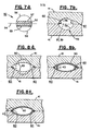
- Figures 6(a) and 6(b) show a semi-circular groove 43 in member 41 and a round coolant tube 90. If, after assembly of the cooling assembly 21, the coolant tube 90 fits perfectly within the surrounding grooves 43 in the two plates 41, good surface-to-surface contact occurs between groove 43 and the surface of tube 90. This condition is shown in Figure 6(a). However, as shown in Figure 6(b), if groove 43 is of different contour than the natural shape of the coolant tube 90, or vise versa, the tube 90 nevertheless conforms to the actual shape of groove 43 since it is conformable. Thus, intimate contact between the tube 90 and plate 41 is still accomplished after the cooling assembly is assembled for operation. The abnormalities in the surface or contour of groove 43 shown in Figure 6(b) are greatly exaggerated for the purposes of clarity of this description.
- FIGS 7(a)-(b) and 8(a)-(c) A preferred embodiment of the grooves 43 is shown in Figures 7(a)-(b) and 8(a)-(c). It is noted that these figures are enlarged schematic illustrations used for clarity of description and as such, are not to any particular scale and the components therein are not necessarily proportionally sized with accuracy to regard to one another.
- the groove 43 when a cross-section thereof is viewed, takes on the contour or profile of a truncated half circle in each plate.
- Figures 7(a)-(b) and 8(a)-(c) are partial cross sections of the cooling assembly similar to that shown in Figure 5.
- a quasi-oval groove such as a truncated half circle rather than a half oval or half circle, has been found to be a very advantageous shape for the grooves 90 in plates 41.
- Figure 7(a) depicts the cross section of a circle contour 50 which, when used as is to form the grooves, produces a half circle groove in each plate.
- the circle 50 has a horizontal center line 54 dividing the circle into upper and lower halves.
- a portion 52 of the circle 50 is cut away as indicated by the cross hatched section of Figure 7(a).
- the remaining portions of the upper and lower portions of the circle 50 are bounded by upper half portion 56 and truncated edge 57 and lower half portion 58 and truncated edge 59, respectively.
- Each of these forms a truncated half circle groove.
- the plates 41 of the cooling assembly are assembled as shown in Figure 7(b) and the upper and lower truncated half, circle grooves in each plate 41, when fitted together to provide a channel for the tube (not shown), form a truncated circle contour for the channel.
- a feature of the truncated half circle grooves is that this shape provides room, at the edges 60 of the groove where the two plates 41 interface, for the walls of the tube to expand.
- Both the oval and truncated circle channel profiles provide such space which is used by the tube during the assembly and operation of the fuel cell.
- the use of the truncated circle profile in the channel provides optimum contact between the tube's outer surface and the surface of the groove while also providing room for expansion, especially during operation of the cell.
- Figures 8(a)-(c) The interaction of the tube 90 with the truncated half circle grooves in each plate is shown in Figures 8(a)-(c).
- Figure 8(a) shows the shape of grooves 43 when plates 41 are assembled, but without the tube 90 within the channel provided by grooves 43.
- the cross-section of the tube 90 is, however, superimposed in dotted lines, over the groove 43 to schematically illustrate that the natural shape of tube 90 is altered in this embodiment of the invention when it is assembled with plates 41.
- Figure 8(b) shows the tube 90 assembled with plates 41.
- the tube 90 takes the approximate shape shown.
- the fuel cell has not been placed in operation as yet and, thus, the grooves 43 still leave some room for expansion in the vicinity of edges 60.
- Figure 8(c) shows the grooves 41 and tube 90 when the fuel cell has been placed in operation and has heated up to its normal operating temperature. Coolant (not shown) is also flowing through the tube 90 in this view. During the time that the fuel cell is brought up to operating temperature the materials therein expand. When Teflon is used for the coolant tube 90, the Teflon expands faster and to a greater degree than the material of plates 41; e.g. a graphite plate. In addition, the coolant flows through the tube 90 with a pressure which tends to push against the interior wall of the tube 90 and expands its outer surface into the vicinity of edges 60.
- the sizes of the grooves 43 and outer diameter of tube 90 are to be chosen so that as much of the periphery of the tube as practical is in contact with the surface of the groove during operation of the cell. However, these sizes, necessarily, should not be such that the expansion of the tube due to the bringing of the cell to operating temperature and the passing coolant through the tube makes the tube force the plates 41 apart. In sizing these elements, it is preferable to leave a slight air gap between the groove edges 60 and the periphery of the tube 90 than risk separation of the plates. A small air gap, such as that shown in Figure 8(c), does not appreciably cut down on the passage of heat from the plates 43 to the coolant in the tube 90. It does, however, provide a reasonable manufacturing tolerance for the grooves and tube.
- the actual size of the tube and the profile of the groove are intimately related to provide the desired surface contact between the two elements. These factors are dependent on the application also.
- the selection of the size of the tube depends, among other things, on the amount of coolant required and the thickness of the tube wall. Once these factors are decided upon and the peripheral size of the tube to be used is determined, the size of the periphery of the tube at cell opeating temperatures and with coolant therein can be determined. This, in turn, is taken into account along with the plate material used to determine the size of the groove to provide optimum contact between the groove and tube.
- a polymeric cooling tube 90 is nestled between two grooved members 41 bonded to one another along two narrow strips adjacent to the edges parallel to the straight sections of the cooling tube.
- Cooling plate materials suitable for high temperature operation and corrosive environment would include strips of polyethersulfone film sandwiched between and bonded to two grooved members 41 made of grapthitized or carbonized plates.
- An alternative embodiment is possible which holds the same grooved members 41 together mechanically until after they are assembled into a fuel cell stack of other device in need of cooling.
- Still another alternative assembly technique is to hold the plates together with the tube in the channel with a bonding medium such as dissolved polyethersulfone which is cured to an appropriate temperature.
- the nature of the member 41 need not be constrained unduly.
- the shape of groove 43 could be constructed so as to deliberately conform the tube 90 into intimate surface contact with groove 43, for instance, an elongated or oval cross-section rather than circular. Also extremely hard materials need not be used for member 41.
- the materials used for member 41 in this configuration could be materials which, in of themselves, conform or collapse around the tube 90 so that intimate contact is fully reached with the tube.
- the cooling tube can be pressed into half-oval shape grooves cut out of whatever surface or surfaces are to be cooled.
- the cooling assembly 21 could consist merely of a Teflon tube and cooling fluid. The complete absence of metal would give this assembly corrosion resistance superior to that of metallic or partly metallic devices whether coated or not.
- the cooling tubes themselves, or alternatively, the entire cooling assembly can be made of a non-corroding material for use in a fuel cell stack.
- the primary advantages of this construction are an easy and low cost fabrication, total safety against corrosion (non-metalllic) and total elimination of shunt currents between cooling plates in the stack without having to otherwise electrically isolate the cooling plates.
- the flexibility of the cooling tube also provides good thermal conduction thereto in of itself since it tends to be pressed up tightly against the surfaces of the grooves in the members 41.
- the tube assembly is temperature tolerant, totally corrosion resistant and totally impervious.
Abstract
Description
- This invention relates to an improved cooling apparatus, and, more specifically, to an improved cooling assembly for use in fuel cell stacks.
- Fuel cell design and operation typically involves conversion of a hydrogen-containing fuel and some oxidant into DC electric power through an exothermic reaction. The chemistry of this reaction is well known and has established parameters and limitations. One such limitation is that the electrochemical reaction produces, as a by-product thereof, substantial waste heat which must be removed in a controlled manner to maintain the cells at their desired operating temperature. For efficient operation, it is generally desirable to maintain the cells at substantially uniform temperature and at a temperature level which is consistent with a controllable rate of reaction of the fuel cells therein.
- Conventional methods for removal of waste heat from the fuel cell environment have traditionally involved the use of a laminar heat exchanger assemblies, or cooling assemblies, incorporated within and arranged parallel to the various other layers from which the fuel cells are constructed. Typically, the components of the cooling assembly take the form of passageways which contain a circulating coolant material. The heat generated within the stack is transferred to the coolant as it is circulated through the stack. The coolant is then brought out of the stack and into a heat exchanger where the heat is removed therefrom before the coolant is recirculated through the stack.
- In the above manner, the cooling assembly enables control over the temperature of the reaction environment of the fuel cell stack and, thus, its rate and efficiency. The pattern of distribution of the coolant passageways within the stack, their relative sizes, the heat capacity of the coolant fluid and the volume of coolant which is circulated through the cooling assembly per unit of time determine the heat transfer capacity of the cooling system. Because the cooling system is generally an integral part of the fuel cell stack, it should be electrically isolated from the stack and also should not be adversely affected by corrosive media within the stack such as the hot electrolyte.
- The problems associated with corrosion as well as the undesirable flow of electrical current from the stack into the cooling loop are described in detail in U.S. Patents 3,964,929; 3,964,930; and 3,969,145. These patents address the problem of the so-called "shunt currents" and attempt to resolve it by electrically insulating the cooling system from ground. This minimizes the driving potential of such currents relative to the coolant. Other techniques for avoiding the problems associated with shunt currents include the use of dielectric coolants.
- The heat exchanger configuration described in these patents is rather typical of that employed by the prior art. Generally, the configuration consists of a series of parallel tubes connected to what is generally referred to as a "plenum". The plenum is a reservoir from which coolant is simultaneously distributed into the parallel tubes which are embedded in a fuel cell cooling assembly. After passage of the coolant through the parallel tubes, it is collected in another plenum and, thereafter, returned, through a cooling loop, to the inlet plenum.
- The cooling assembly tubes are composed of electrically conductive material such as copper. Water can be used as the coolant and the metal tubes are coated either on their internal or external surfaces with a dielectric material such as polytetrafluorethylene. This coating is used to reduce the possibility of shunt currents and corrosion of the tubes. The coated tubes are located in passageways formed in the plates of fuel cells in the stack. However, due to manufacturing tolerances, it is difficult to avoid voids such as spaces between the tubes and the walls of the passageways. Since air is a poor conductor of heat, such air spaces can be filled with a thermally-conductive grease which is compatible with the electrolyte to maximize heat transfer from the cells to the coolant.
- These types of systems also use a sacrificial anode material at the tube ends to guard against corrosion. In addition, there is the possibility of discontinuities occurring in the Teflon layer such as by manufacturing imperfections, differential thermal expansion, damage during the assembly process, poor bonding, etc. This causes two problems; first the corrosive media in the fuel cell will be able to directly attack the tube, and, second, the thermal contact will be diminished.
- A variation in cooling assembly design is disclosed in U.S. Patent 4,233,369. In this patent, a fibrous, porous coolant tube holder, which also serves as a member through which a reactant gas can travel, is used to hold copper coolant tubes. The tubes, held in channels in the holder, are connected to a coolant inlet header and coolant outlet header. Between the headers, the tubes pass through the stack, make a U-turn and pass back through the stack. The tubes are pressed into the channels and have caulking between the channel walls and tube. In addition to reduced corrosion, this system makes the separator plate thinner and easier to manufacture.
- Other techniques are known for bringing coolant materials into a fuel cell stack. For instance, a tubeless system has been used wherein a metal plate is grooved in a pattern on its surface with one or more inlets and outlets. The grooved surface of the plate is then covered with a second ungrooved metal plate, called a brazing sheet, to create an assembly having enclosed coolant passageways and coolant inlet and outlets. In addition, similar passageways can be constructed by assembling two such brazing plates with partitions therebetween which form coolant passageways.
- It is evident that the demands upon the cooling systems for fuel cells are significantly greater and more specialized than those encountered by other devices in different heat transfer environments. U.S. Patents 1,913,573; 2,8l9,731; 2,820,615; 2,864,591; and 3,847,194 are illustrative of some of the conventional heat transfer devices found in areas other than the fuel cell-related technologies. In virtually all the heat exchangers described in the immediately foregoing list of patents, the environmental setting contemplated for their use is much more forgiving than that encountered in fuel cells.
- Accordingly, the present invention provides a simplified cooling assembly that maximizes heat transfer from the fuel cell stack to the coolant without undue manufacturing and assembly tolerances. The cooling assembly is essentially non-corrosive in the fuel cell environment and avoids shunt currents without the need for additional electrical isolation thereof from adjacent fuel cells within the stack. The assembly can be made as an integral component of a fuel cell and is effective without the use of the coatings used by prior art devices.
- The fuel cell cooling assembly described herein utilizes a conformable conduit for carrying coolant through the assembly. The conduit is held by a member or members containing channels which, upon assembly with the conduit, conform the conduit into intimate contact with the surface of the channels to maximize heat transfer from the fuel cell to the coolant.
- In one embodiment, the conduit can comprise a non-corroding, metal-free, dielectric material. The conduit can also be a continuous tube having periodic corrugations therein to accomodate the bends necessary to arrange the conduit into a serpentine configuration without crimping. The conduit maximizes heat transfer in a given area while necessitating only one inlet and one outlet for the coolant.
- In another embodiment, the cooling assembly can be used in a stack of discrete fuel cells in which two of the discrete adjacent cells are separated from one another by a manifold-free heat exchanger assembly. The assembly comprises a termination plate from each of the adjacent cells which, in combination, form a predetermined channel pattern to intimately cradle a continuous, non-corridible, crimp-resistant, electrically insulated conduit.
- This invention will now be described by reference to the following drawings and description in which like elements have been given common reference numerals:
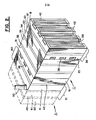
- Figure 1 is a schematic representation of a fuel cell assembly comprising a plurality of stacked fuel cells with intermediate cooling plates and terminal current collecting plates.
- Figure 2 is a perspective view of a portion of the fuel cell assembly of Figure 1, illustrating an individual fuel cell in greater detail.
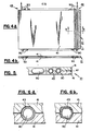
- Figures 3(a) and 3(b) are perspective views showing two embodiments of the cooling assembly.
- Figure 4 is a view in partial cross section of a cooling assembly which has been isolated from the fuel cell assembly illustrating the serpentine arrangement of conduit means as it weaves through the predetermined channel pattern formed in the members which retain the conduit means.
- Figure 5 is a cross section through Figure 4 at Section A-A.
- Figures 6(a) and 6(b) are schematic illustrations depicting the intimate contact between the conduit means and members of the cooling assembly.
- Figures 7(a) and (b) are schematic illustrations of the formation of the truncated half-circle grooves.
- Figure 8(a)-(c) are schematic illustrations of the coolant tube and the grooves at various times.
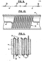
- Figure 9 is a schematic illustration of the coil pattern after the coil material is stretched out between those sections thereof which accommodate bends in the coolant tube.
- Figure 10 is a schematic illustration of- the coil support in the coolant tube before the tube is bent, the tube being partially cut away.
- Figure 11 is a schematic illustration of the coil support in a tube arranged in serpentine configuration.
- An exemplary fuel
cell stack assembly 10 employing the invention is shown in Figures 1 and 2. Thestack assembly 10 includes a plurality of fuel cells 11. Hydrogengas input manifolds 12 are arranged along one side of thestack assembly 10. Although a plurality ofmanifolds 12 are shown for each group of fuel cells 11, a single such manifold arrangement could be used if desired. Themanifolds 12 are connected to a source ofhydrogen gas 14. Hydrogengas collecting manifolds 15 are arranged along the opposing stack side in correspondence with the hydrogen gas input manifolds 12. Here again, although a plurality ofmanifolds 15 are shown, a single such manifold could be used if desired. The collectingmanifolds 15 are connected to a hydrogen gas discharging orrecirculating system 17. The hydrogen gas from the input manifolds 12 flows throughgas distribution plates 18 to the collectingmanifolds 15. - In similar fashion, a plurality of oxygen input manifolds (not shown) are arranged along another stack side connecting the one stack side and the opposing stack side. These oxygen manifolds are connected to an
oxygen source 19. The oxygen may be supplied in the form of air rather than pure oxygen if desired. A plurality of oxygen collecting manifolds (not shown) are arranged along the stack side opposing the stack side having the oxygen input manifolds connecting the respective one stack side and opposing stack side. The stack sides at which the oxygen manifolds are arranged are generally stack sides other than the ones at which the hydrogen input manifold and hydrogen collecting manifold are connected. The oxygen manifolds are also, connected to an oxygen storage or recirculating system (not shown). The oxygen from the input manifolds flows through the oxygengas distribution plates 20 to the respective collecting manifolds. -
Cooling assemblies 21 are arranged periodically between adjacent fuel cells 11 to effect the desired degree of cooling. In the embodiment shown in Figure 1, threecooling assemblies 21 are shown arranged intermediate each group of four cells 11. The cooling material, either liquid or gas, which flows through the coolingassembly 21 can be any suitable material. For instance, it can be a dielectric fluid such as a high temperature oil coolant manufactured by Multitherm Corporation under the trade name PG-1. In the alternative, it can be a non-dielectric coolant such as water or a water and stream mixture. - A
pump 22 circulates the coolant by way ofpassageway 23 anddistribution reservoir 24 into therespective cooling assemblies 21. Thedistribution reservoir 24 is joined to each individual cooling assembly by direct connection to the inlet port of thecontinuous coolant conduit 90 of coolingassembly 21.Conduit 90 is shown in two different configurations in Figures 3(a) and 3(b). - After passing through
conduit 90, the coolant flows into thecollection reservoir 25. Thereservoir 25 is connected to aheat exchanger 26 which reduces the temperature of the coolant to the desired input temperature before it is recirculated through theconduit 90.Collection reservoir 25 is joined to thecooling plate assemblies 21 by direct connection to the outlet port ofcontinuous conduit 90. Acoolant passageway 27 connects theheat exchanger 26 back to thepump 22 so that the coolant can be recirculated through therespective cooling assemblies 21. -
Reservoirs fuel cell stack 10 has a number ofcooling assemblies 21, and, even then, the reservoirs are connected directly to eachindividual cooling assembly 21 at a single point. Alternatively, however, cooling assembly designs could be made wherein more than onecontinuous conduit 90 operates in parallel to effect serial distribution of coolant throughout the plate or wherein such multiple continuous conduits are complementary to one another and each independently distributes coolant throughout the plate. - The fuel cells 11 and the
cooling assemblies 21 are basically electrically conductive so that when they are stacked as shown, the fuel cells 11 are connected in series. In order to connect thestack assembly 10 to a desired electrical load,current collecting plates 28 are employed at the respective ends of thestack assembly 10.Positive terminal 29 andnegative terminal 30 are connected to thecurrent collecting plates 28, as shown and may be connected to the desired electrical load by any conventional means. - Any suitable-fuel cell design can be utilized with the cooling assembly disclosed herein. Figure 2 depicts a cooling
assembly 21 together with portions of a representative fuel cell stack shown in more detail. This figure includes two portions of the stack immediately surrounding coolingassembly 21. Each of the stack portions includes in this embodiment, a plurality of fuel cell units 11. The stack portion to the right of the cooling assembly 21 (in solid lines) shows detail of the various components of the cell 11. The stack portion to the left of cooling assembly 21 (in dotted lines) is representative of another similar fuel cell. Although the portion of the stack in dotted lines is shown slightly removed from the portion in solid lines for clarity, it is understood that these two portions are in contact with each other andconduit 90 in actual operation to provide good electrical and thermal conductivity through the two portions. - Each fuel cell 11, as depicted in Figure 2, includes a hydrogen
gas distribution plate 18 and an oxygen orair distribution plate 20. Arranged intermediate between the respectivegas distribution plates 18 .and 20 are the following elements starting from the hydrogen gas-distribution-plate 18;anode 31,anode catalyst 32,electrolyte 33,cathode catalyst 34 andcathode 35. These elements, 31-35, of the fuel cell 11 may be formed of any suitable material in accordance with conventional practice. - The hydrogen
gas distribution plate 18 is arranged in contact with theanode 31. Typically, the anode comprises a carbon material having pores which allow the hydrogen fuel gas to pass through the anode to theanode catalyst 32. Theanode 31 is preferably treated with Teflon (polytetrafluoroethylene) to prevent theelectrolyte 33, which i's preferably an immobilized acid, from flooding back into the area of the anode. If flooding were allowed to occur, the electrolyte would plug up the pores in theanode 31 and lessen the flow of hydrogen fuel through the fuel cell 11. Theanode catalyst 32 is preferably a platinum-containing catalyst. - The fuel cell 11 is formed of an electrically conductive material, such as a carbon based material, except for the electrolyte layer which does not conduct electrons but does conduct hydrogen ions. The various elements, 18, 31-35, and 20 are 'compressed together under a positive pressure during the cell assembly process. The
electrolyte 33 can be made of any suitable material such as phosphoric acid. The acid can be dispersed in a gel or paste matrix so that it is immobilized and not a free liquid. An exemplary electrolyte matrix could comprise a mixture of phosphoric acid, silicon carbide particles and Teflon particles. Thecathode catalyst 34 and thecathode 35 can be formed of materials similar to theanode catalyst 32 andanode 31. - All of the elements of the fuel cell 11 are arranged after assembly in intimate contact as shown in Figure 2. In order to provide a relatively compact electrically interconnected stack assembly of a plurality of adjacent individual fuel cells 11, the
bipolar assembly 36 is used to easily connect together adjacent fuel cells 11. Thebipolar assembly 36 is comprised of a hydrogengas distribution plate 18 and an oxygen orair distribution plate 20 with the impervious interface layer ofplate 37 arranged between them. Therefore, thebipolar assembly 36 is comprised of the hydrogengas distribution plate 18 of one cell 11 and the oxygen or airgas distribution plate 20 of the next adjacent cell 11. The interface layer, orplate 37, may comprise an impervious carbon plate or any other conventional interface as may be desired. Thebipolar assembly 36, theplates interface 37 therebetween are securely connected together as a unit so as to have good electrical conductivity. - In order to facilitate the gas flow in the
gas distribution plates grooves grooves 38 in the hydrogengas distribution plate 18 are arranged orthogonally or perpendicularly to thegrooves 39 in the oxygen or airgas distribution plate 20. This allows the grooves to be easily connected to respective input andoutput manifolds cell stack assembly 10. - Although grooves within a particular plate, such as
plates grooves - The
gas distribution plates respective anode 31 orcathode 35. In order to more evenly distribute the respective gases at theanode 31 orcathode 35 plate surfaces, thegas distribution plates plates channels respective anode 31 orcathode 35. - At the ends of the stack, as seen in Figure 1, there are current collecting
plates 28. These can be made an integral part of the adjacent gas distribution plate assembly on the end cell in the stack. Optionally, an impervious material, such as aluminum can be placed between the gas distribution plate and current collecting plate or the current collecting plate itself can be made of such a material. - The cooling
assembly 21, as shown in Figure 2 and also Figure 4, has at least one coolant conduit means such asconformable tube 90. The conduit carries coolant through the coolingassembly 21. Thecooling assemblies 21 shown in Figures 3-5 include a means for holding theconduit tube 90 in the assemblies including a member orplate 41. Themember 41, when assembled with the conduit tube, conforms at least a portion of the conduit tube into intimate contact with themember 41. - The embodiment of the cooling
assembly 21 shown in Figure 2 includes themember 41 as an integral part of thegas distribution assembly 40. Theassembly 40 includes hydrogengas distribution plate 18 and a gasimpervious plate 42, which is optional, assembled together with themember 41. A similar assembly is shown in dotted lines on the left side oftube 90, except that the oxygengas distribution plate 20 is made an integral part of the assembly. Thegas distribution plates member 41. - The
improved cooling assembly 21 can take several embodiments, two of which are shown in more detail in Figures 3(a) and 3(b). In a first embodiment shown in Figures 3(a),conduit 90 is a single, continuous tube having one inlet and one outlet for coolant. The tube is arranged in a serpentine or similar pattern withinmembers 41 to effect good heat transfer between themembers 41 and thetube 90. Although thetube 90 is shown as having its turning bends outsidemembers 41 to sweep back and forth acrossmembers 41, the turning bends can alternatively be placed within themembers 41. In a second embodiment shown in Figure 3(b),conduit 90 is actually a plurality ofconduit tubes 90 passing through themembers 41. Coolant, in this latter embodiment, is brought in and exited through a manifold comprising conduit feeders or headers 90' so that allconduits 90 can be fed off a single conduit feeder. - The embodiment shown in Figure 3(a) is the preferred one. This is the manifold-free arrangement which is simpler and less expensive to manufacture and assemble as compared to the arrangement shown in Figure 3(b). The phrase "manifold-free" is intended as descriptive of a heat exchanger in which a coolant is distributed from the portion of the cooling loop which is remote from the fuel cells directly into the cooling assembly so as to provide for serial flow of coolant throughout the cooling assembly. This is in sharp contrast to the devices illustrated in the prior art whereby coolant is simultaneously distributed from a common manifold into a plurality of parallel, and highly localized, channels of the cooling plate each of which is served by individual unconnected coolant paths.
- As can be readily appreciated, the phrase "manifold-free" is not, however, intended as exclusive of a coolant distribution system wherein coolant from a common source is simultaneously distributed into two or more continuous channels or conduits arranged in parallel, or otherwise, within the cooling assembly. The coolant flow in this latter type system would not be of the highly localized nature as in the prior art, but rather would and could provide (a) a redundant coolant flow, (b) two or more patterns which are complementary to one another, or (c) a coolant flow pattern in which the direction of flow in one channel is countercurrent to the flow in the other. In any event, this predetermined pattern of distribution of a second continuous channel/conduit would not be highly localized as is dictated by the prior art systems in which a manifold is an essential element for the simultaneous distribution of coolant through such unconnected localized channels.
- In the event a corrosion sensitive material is used in the fabrication of this cooling assembly, it should be effectively isolated from the electrolyte and other hostile chemical agents. In the most preferred embodiments of this invention, the cooling assembly is essentially metal-free; that is, none of the components thereof which are actually or potentially exposed to the corrosive environment of the fuel cell are composed of a corrosive material such as metal. For example,
conduit 90 is preferably a fluorinated hydrocarbon polymer. - In fuel cells, the gas distribution plates, such as 18 and 20 in Figure 2, are commonly made of a porous carbon material. To protect the
members 41 from corrosion, an improved interfacial layer configuration can be used betweenmembers 41 andgas distribution plates impervious plate 42. This interfacial configuration may have, for example, a perforate conductive layer such as a metallic mesh material having a resin, such as polyethersulfone, substantially filling any void space in the mesh. The interface can be assembled between a cell in the fuel cell stack and the cooling assembly. - Figures 4 and 5 show further views of the cooling
assembly 21. In this embodiment, the coolingassembly 21 consists of conformable coolant conducting means, thetube 90, for carrying coolant through the assembly. Coolant is brought in through one end of thetube 90, the inlet 45, and removed from the assembly at the other end oftube 90, theoutlet 46. A means similar to that described in Figure 1 is used to circulate the coolant through the cooling assembly. - The coolant assembly is located adjacent a cell or between two adjacent cells in a fuel cell stack as shown in Figure 1. The cooling apparatus includes a means for holding the
tube 90, in this embodiment shown asmembers 41. Themember 41 has means therein for holding thetube 90 such aschannels 43 shown in Figure 5. When themembers 41 are assembled together with thetube 90, at least a portion of thetube 90, and particularly the surface area of the tube, conforms to make intimate contact with themember 41. - The conduit means, the
tube 90, is preferably non-corrodible and metal-free. Thetube 90 can be made of any suitable material such as a dielectric material. One material suitable for this purpose is polytetrafluorethylene lTeflon). Thus,tube 90 can be a Teflon tube having about a 0.270 inch outside diameter and a 0.015 inch wall thickness. It also is preferably a single, continuous length of tube having one inlet and one outlet to eliminate complex inlet and outlet manifolds. It can be placed in a zig-zag or serpentine configuration with periodic bends therein to sweep it back and forth across the coolingmember 41. The bends intube 90 may occur outside themember 41, as shown in Figure 4, or, alternatively, may occur within the member. - In the use of a Teflon tube in cooling assemblies, some consideration should be given to the pressure limits of the tube. A tube such as the type described immediately above was operated in a fuel cell having a normal operating temperature of about 350-400 degrees F. It was found that the specific tube used might burst if coolant pressures were maintained in the area of 100 psi and above. On the other hand, bursting did not occur when the pressure was maintained in a range up to approximately 50-60 psi.
- The areas of the
tube 90 which are bent can be made to bend as desired by any suitable means. For instance, thetube 90 can be manufactured to have predetermined bends in it such as approximately 180 degrees before assembly withmember 41. Its shape can conform to the serpentine arrangement it should follow to pass throughchannels 43 when the cooling assembly is put together. Thetube 90 can also be made of a straight section of tubing which is bent into the serpentine arrangement during assembly withmembers 41. To ease the bending process, corrugated segments can be periodically arranged along its length to allow for short radius bending thereof without crimping or other damage or failure occurring to the tube as it is arranged within the predetermined channel pattern formed bymembers 41. - The corrugations are typically less than one or two inches in length and they permit a tight bending radius to allow a tightly-packed, zig-zag geometry that yields a high ratio of heat transfer area to total plate area. The bends can be 180 degrees or some other angle to accommodate the pattern of sweeping the tube back and forth across
members 41. One method of creating such corrugations is to apply a hot mandrel to those sections of the tube where the tube is to be bent. The tube material, such as Teflon, is thereby softened by the hot mandrel while also being constrained by the mandrel. The tube wall in this condition takes on a fluted (or corrugated) configuration. - Instead of corrugating
tube 90 in its portions which are to be bent, other approaches can be used in bending thetube 90 to allow short radii without the risk of crimping the tube or causing other damage to it. One such approach is to provide a support means in the tube to guard against such damage. The internal support can be placed throughout the length of the tube or only at the locations at which the tube is to be bent. Such a support can be located entirely within the tube's central passageway that carries the coolant, and it can be an additional component assembled to the tube. - A preferred type of internal support means is carried out by inserting wire coils inside the tube at the locations that the tube is to be bent. This is shown in Figures 9-11.
Such coils 70 can have a diameter slightly less than the inside diameter of thetube 90 and enable the coolant to pass through inside diameter of the coil as well as around the coils and between the coils and tube wall. - Such coils have been found to prevent excess crimping in the tube wall when the tube is formed into short radius bends 72. The coils at the bends can be connected to one another by any suitable means such as by a
straight section 74 of wire therebetween. The coils can be inserted into the tubing by their leading end and fully pushed into the entire length of the tube. In this manner, the tightly-wrappedcoiled portions 70 are located in theareas 72 of the tube to be bent while thestraight sections 74 are located along the tube between the bends. - The coils can be made of any suitable material. For instance, they can be safely made of a metallic material such as steel since they are completely located in the tube and, thus, are not exposed to the corrosive materials used in the fuel cell environment. The approach of using an internal support such as a coil in the tube is believed significantly less expensive to manufacture than the placement of corrugations in the tube material itself as described above. The shape, size and configuration of the internal support can be any suitable one so long as the coolant is allowed to flow in the tube as intended.
- One manner of forming the metal coil internal support is to start with a length of tightly-wrapped coil or spring stock of an appropriate length and diameter and stregth out the coil material in conformance with the frequency of bends in the tube. A small, still tightly-wrapped
length 70 can be left between eachuncoiled section 74 sufficient to accommodate a bend in the tube. The portion of the coil support structure between the bends is then simply a straight, uncoiled section of coil material joined to tightly-wrapped sections of coil at the bends. In this manner, the entire internal support can be made of a single continuous length of coil material. - The coil pattern; e.g., tightly-wrapped coil sections separated by uncoiled sections, could be manufactured by hand with suitable coil stretching and anhoring tools to match the intended configuration of the bends of the tube in the cooling assembly. To provide a coil pattern of greater dimensional control and accuracy, any conveniently available mechanism can be used. For instance, an ordinary lathe was used to process a length of tightly-wrapped coiled material into a coil pattern with sections of tightly-wrapped coil interspersed with uncoiled, stretched out lengths of coil material. The lathe was used simply as a holding and stretching device and not in its usual machining capacity.
- In the lathe process, the coil was placed in the chuck of the lathe with a section extending out towards the carriage along the lathe bed. A clamp or some other appropriate forcing device was attached to the extending section of the coil, but leaving a tightly coiled portion beyond. The clamp was then moved away from the chuck to stretch out the coil into a somewhat straight section so as to def orm the coil material in that area.
- The above procedure provided a tightly-wrapped coil section separated from the rest of the coil by a relatively unwrapped or straight section of coil material. The coil stock was then loosened in the chuck and moved a bit to allow another tightly-wrapped coil section thereof to extend beyond the chuck. The clamp was then again fastened on the coil stock having a tightly-wrapped portion between it and the previously stretched out portion to be placed in a bend in the tube. After this section was stretched, the process was repeated until there were enough tightly-wrapped coiled sections of coil material between stretched out sections to accommodate all the bends in the tube.
- The coil pattern manufactured in the above described manner was used in a cooling assembly with good results. There was enough space within the inner diameter of the coil so as not to unduly impede the flow of coolant. For instance, a tube having a nominal size of 1/4 inch diameter was used which has an inside diameter of approximately 0.270 inches. A coil having an outside diameter slightly less than the inside diameter of the tube, and inside diameter of approximately 0.190-0.200 inches, made in the above-described manner, was screwed into a length of tube approximately 30 feet long. In using the tube with the coil inserted therein, the pressure drop across the entire tube length was held to less than 20 psi.
- In addition to the coil-type internal support, other types of internal supports can be used. For instance, an internal cylinder or tube, or member of other configuration, could be placed in the coolant tube to ease crimping in the bend areas. Such an internal tube should be rigid so as not to overly restrict or impede coolant flow yet enable small radius bends in the coolant tube. Internal tubes for this purpose can be made out of any suitable material such as plastic or metal.
- The
channels 43 withinmembers 41 can take any pattern which is suitable for cooling. The contour of thechannels 43 may preferably have the shape that approximately conforms with the natural peripheral shape oftubes 90. This is so that whenmembers 41 are placed over thetubes 90, there is an intimate surface-to-surface contact between the two components and a minimization of any air spaces or other voids therebetween. Any such gaps that might otherwise exist are closed by the tube conforming to the surface contour of thechannels 43. The sizing of thechannels 43 relative to the sizing of thetubes 90 may be such that the channel at least slightly compresses the tube periphery when the two are assembled into operating positions. Thus, thechannel 43 takes on a shape which closely conforms to thetube 90 when the two are assembled together. - The cooling
assembly 21 can be made as a separate unit from the individual cells of the cuel cell stack so thatmembers 41 and conduit means 90 can be placed or inserted periodically along the stack to permit cooling. Alternatively,members 41 can be made part of or integral with the gas distribution plates of the fuel cell adjacent to the cooling assembly. In this configuration, two such stack portions having anintegral member 41 on the end cell can be assembled with the cooling tubes to form a cooling assembly within the stack. - The function of the straight sections of
tube 90 is to effect the ,transfer of heat from thegrooved surfaces 43 inmembers 41 in which they are nestled. Themembers 41, containing the grooved surfaces, can be made of any solid, thermally and electrically conductive material, such as any material commonly used in hot fuel cell or battery plates. - The grooves or
channels 43 inmember 41 can assume any suitable cross-section profile to accomplish the result desired. The channel shape can be formed to conform thetube 90 to its shape and thereby cause intimate contact therewith when assembled. For instance, the grooves in eachmember 41 can be cut in an approximately half-round or half-oval cross-section. The surfaces of themembers 41 can then be mechanically pressed together with the grooves over thetube 90. The surfaces of the members between the grooves can be brought into contact, as shown in Figures 5-6, to create an electrical contact over the areas adjacent to the grooves. The half-oval grooves allow the coolingtube 90 to conform easily to the surface area of thegrooves 43 and, thus, maintain thermal contact without impeding the electrical contact betweenmembers 41 or the flow of coolant within the coolingtube 90. - The shape or contour of
channels 43 are subject to manufacturing variances. Ifnon-conformable tubes 90 were used therein and large variances occurred in the dimensions and contour of thechannels 43 or the tubes,rigid cooling tubes 90 would not conform to the manufactured shape ofchannel 43. This would create an air space produced between thetube 90 andgroove 43. This problem is addressed in the background patents mentioned herein. These patents dislose the use of caulking material in the gaps to improve heat transfer. By using a conformable material fortube 90, such manufacturing variance problems would be automatically overcome by the tendency of thetube 90 to conform to the actual contour ofchannels 43. - Figures 6(a) and 6(b), show a
semi-circular groove 43 inmember 41 and around coolant tube 90. If, after assembly of the coolingassembly 21, thecoolant tube 90 fits perfectly within the surroundinggrooves 43 in the twoplates 41, good surface-to-surface contact occurs betweengroove 43 and the surface oftube 90. This condition is shown in Figure 6(a). However, as shown in Figure 6(b), ifgroove 43 is of different contour than the natural shape of thecoolant tube 90, or vise versa, thetube 90 nevertheless conforms to the actual shape ofgroove 43 since it is conformable. Thus, intimate contact between thetube 90 andplate 41 is still accomplished after the cooling assembly is assembled for operation. The abnormalities in the surface or contour ofgroove 43 shown in Figure 6(b) are greatly exaggerated for the purposes of clarity of this description. - A preferred embodiment of the
grooves 43 is shown in Figures 7(a)-(b) and 8(a)-(c). It is noted that these figures are enlarged schematic illustrations used for clarity of description and as such, are not to any particular scale and the components therein are not necessarily proportionally sized with accuracy to regard to one another. In this embodiment, thegroove 43, when a cross-section thereof is viewed, takes on the contour or profile of a truncated half circle in each plate. Figures 7(a)-(b) and 8(a)-(c) are partial cross sections of the cooling assembly similar to that shown in Figure 5. When a conformable material is used fortube 90, a quasi-oval groove, such as a truncated half circle rather than a half oval or half circle, has been found to be a very advantageous shape for thegrooves 90 inplates 41. - The term "truncated half circle" is described in conjunction with Figures 7(a) and (b). Figure 7(a) depicts the cross section of a
circle contour 50 which, when used as is to form the grooves, produces a half circle groove in each plate. Thecircle 50 has ahorizontal center line 54 dividing the circle into upper and lower halves. In order to form the truncated half circle groove, aportion 52 of thecircle 50 is cut away as indicated by the cross hatched section of Figure 7(a). When this is done, the remaining portions of the upper and lower portions of thecircle 50 are bounded byupper half portion 56 andtruncated edge 57 andlower half portion 58 andtruncated edge 59, respectively. Each of these forms a truncated half circle groove. - The
plates 41 of the cooling assembly are assembled as shown in Figure 7(b) and the upper and lower truncated half, circle grooves in eachplate 41, when fitted together to provide a channel for the tube (not shown), form a truncated circle contour for the channel. A feature of the truncated half circle grooves is that this shape provides room, at theedges 60 of the groove where the twoplates 41 interface, for the walls of the tube to expand. Both the oval and truncated circle channel profiles provide such space which is used by the tube during the assembly and operation of the fuel cell. However, the use of the truncated circle profile in the channel provides optimum contact between the tube's outer surface and the surface of the groove while also providing room for expansion, especially during operation of the cell. - The interaction of the
tube 90 with the truncated half circle grooves in each plate is shown in Figures 8(a)-(c). Figure 8(a) shows the shape ofgrooves 43 whenplates 41 are assembled, but without thetube 90 within the channel provided bygrooves 43. The cross-section of thetube 90 is, however, superimposed in dotted lines, over thegroove 43 to schematically illustrate that the natural shape oftube 90 is altered in this embodiment of the invention when it is assembled withplates 41. Figure 8(b) shows thetube 90 assembled withplates 41. Thetube 90 takes the approximate shape shown. The fuel cell has not been placed in operation as yet and, thus, thegrooves 43 still leave some room for expansion in the vicinity of edges 60. - Figure 8(c) shows the
grooves 41 andtube 90 when the fuel cell has been placed in operation and has heated up to its normal operating temperature. Coolant (not shown) is also flowing through thetube 90 in this view. During the time that the fuel cell is brought up to operating temperature the materials therein expand. When Teflon is used for thecoolant tube 90, the Teflon expands faster and to a greater degree than the material ofplates 41; e.g. a graphite plate. In addition, the coolant flows through thetube 90 with a pressure which tends to push against the interior wall of thetube 90 and expands its outer surface into the vicinity of edges 60. - It can be appreciated, in constrast, that when the
grooves 43 are formed by half circles and the channel for thetube 90 is in the shape of a full circle when theplates 43 are assembled, there is no room for expansion of thetube 90. Thus, if the diameter oftube 90 is approximately the same size as the groove, there is little place for thetube 90 to expand when the cell is brought up to operating temperature and/or coolant is passed through the tube. Such expansion could force theplates 41 apart after assembly which would deteriorate the intended performance of the cell. - On the other hand, if the outer size of
tube 90 was reduced relative to the groove size to allow adequate expansion room within the groove, the smaller tube would be able to flop around in the plates after assembly whenever the cell is not at full operating temperature. This is disadvantageous in that it may cause damage to the coolant tube, such as during shipping and handling of the fuel cell, and little of the tube's periphery would be continuously in place against the surface ofgrooves 43 at all times. - The sizes of the
grooves 43 and outer diameter oftube 90 are to be chosen so that as much of the periphery of the tube as practical is in contact with the surface of the groove during operation of the cell. However, these sizes, necessarily, should not be such that the expansion of the tube due to the bringing of the cell to operating temperature and the passing coolant through the tube makes the tube force theplates 41 apart. In sizing these elements, it is preferable to leave a slight air gap between the groove edges 60 and the periphery of thetube 90 than risk separation of the plates. A small air gap, such as that shown in Figure 8(c), does not appreciably cut down on the passage of heat from theplates 43 to the coolant in thetube 90. It does, however, provide a reasonable manufacturing tolerance for the grooves and tube. - The actual size of the tube and the profile of the groove are intimately related to provide the desired surface contact between the two elements. These factors are dependent on the application also. The selection of the size of the tube depends, among other things, on the amount of coolant required and the thickness of the tube wall. Once these factors are decided upon and the peripheral size of the tube to be used is determined, the size of the periphery of the tube at cell opeating temperatures and with coolant therein can be determined. This, in turn, is taken into account along with the plate material used to determine the size of the groove to provide optimum contact between the groove and tube.
- The optimum system results when the tube has substantial contact with the groove when the cell is not at operating temperature, as shown in Figure 8(b),, and almost, but not complete contact with the groove when the cell is at operating temperature, as shown in Figure 8(c). In this manner, certain areas of the tube's surface are always in contact with the surface 'of the groove thereby eliminating the possibility of new gaps being generated between the two as the fuel cell is cycled on and off or over a range of operating temperature.
- In the cooling assembly embodiment shown in Figure 5, a
polymeric cooling tube 90 is nestled between twogrooved members 41 bonded to one another along two narrow strips adjacent to the edges parallel to the straight sections of the cooling tube. Cooling plate materials suitable for high temperature operation and corrosive environment would include strips of polyethersulfone film sandwiched between and bonded to twogrooved members 41 made of grapthitized or carbonized plates. An alternative embodiment is possible which holds the samegrooved members 41 together mechanically until after they are assembled into a fuel cell stack of other device in need of cooling. Still another alternative assembly technique is to hold the plates together with the tube in the channel with a bonding medium such as dissolved polyethersulfone which is cured to an appropriate temperature. - The nature of the
member 41 need not be constrained unduly. The shape ofgroove 43 could be constructed so as to deliberately conform thetube 90 into intimate surface contact withgroove 43, for instance, an elongated or oval cross-section rather than circular. Also extremely hard materials need not be used formember 41. - The materials used for
member 41 in this configuration could be materials which, in of themselves, conform or collapse around thetube 90 so that intimate contact is fully reached with the tube. The cooling tube can be pressed into half-oval shape grooves cut out of whatever surface or surfaces are to be cooled. In this case, the coolingassembly 21 could consist merely of a Teflon tube and cooling fluid. The complete absence of metal would give this assembly corrosion resistance superior to that of metallic or partly metallic devices whether coated or not. - The cooling tubes themselves, or alternatively, the entire cooling assembly, can be made of a non-corroding material for use in a fuel cell stack. The primary advantages of this construction are an easy and low cost fabrication, total safety against corrosion (non-metalllic) and total elimination of shunt currents between cooling plates in the stack without having to otherwise electrically isolate the cooling plates. The flexibility of the cooling tube also provides good thermal conduction thereto in of itself since it tends to be pressed up tightly against the surfaces of the grooves in the
members 41. The tube assembly is temperature tolerant, totally corrosion resistant and totally impervious. - It is to be understood that the above described embodiment of the invention is illustrative only, and that modifications thereof may occur to those skilled in the art. Accordingly, this invention is not to be regarded as limited to the embodiment as disclosed herein, but is to be limited only as defined by the appended claims.
Claims (16)
Priority Applications (1)
| Application Number | Priority Date | Filing Date | Title |
|---|---|---|---|
| AT84303694T ATE30361T1 (en) | 1983-06-02 | 1984-06-01 | COOLING DEVICE FOR FUEL CELLS. |
Applications Claiming Priority (6)
| Application Number | Priority Date | Filing Date | Title |
|---|---|---|---|
| US50049883A | 1983-06-02 | 1983-06-02 | |
| US50046483A | 1983-06-02 | 1983-06-02 | |
| US500464 | 1983-06-02 | ||
| US500498 | 1983-06-02 | ||
| US500465 | 1983-06-02 | ||
| US06/500,465 US4583583A (en) | 1983-06-02 | 1983-06-02 | Fuel cell crimp-resistant cooling device with internal coil |
Publications (2)
| Publication Number | Publication Date |
|---|---|
| EP0128023A1 true EP0128023A1 (en) | 1984-12-12 |
| EP0128023B1 EP0128023B1 (en) | 1987-10-21 |
Family
ID=27414149
Family Applications (1)
| Application Number | Title | Priority Date | Filing Date |
|---|---|---|---|
| EP84303694A Expired EP0128023B1 (en) | 1983-06-02 | 1984-06-01 | Cooling assembly for fuel cells |
Country Status (3)
| Country | Link |
|---|---|
| EP (1) | EP0128023B1 (en) |
| JP (1) | JPH0715355B2 (en) |
| DE (1) | DE3466913D1 (en) |
Cited By (9)
| Publication number | Priority date | Publication date | Assignee | Title |
|---|---|---|---|---|
| FR2557373A1 (en) * | 1983-12-23 | 1985-06-28 | United Technologies Corp | COOLING SYSTEM FOR AN ELECTROCHEMICAL FUEL CELL |
| EP0700110A1 (en) * | 1994-08-05 | 1996-03-06 | Electric Fuel (E.F.L.) Limited | Cooled zinc-oxygen battery |
| DE19636904C1 (en) * | 1996-09-11 | 1997-11-27 | Forschungszentrum Juelich Gmbh | Plate- or rod-shaped fuel cell cooling element |
| DE19636902C1 (en) * | 1996-09-11 | 1998-04-23 | Forschungszentrum Juelich Gmbh | Fuel cell stack |
| EP1363342A1 (en) * | 2001-02-23 | 2003-11-19 | Sanyo Electric Co., Ltd. | Fuel cell |
| EP1416558A2 (en) * | 2002-08-12 | 2004-05-06 | General Electric Company | Method and apparatus for fuel cell thermal management |
| WO2009036913A1 (en) * | 2007-09-19 | 2009-03-26 | Zentrum für Sonnenenergie- und Wasserstoff-Forschung Baden-Württemberg Gemeinnützige Stiftung | High-temperature polymer electrolyte membrane fuel cell (ht-pemfc) including apparatuses for cooling said fuel cell |
| EP2650960A4 (en) * | 2011-01-26 | 2016-09-21 | Lg Chemical Ltd | Cooling element having improved assembly productivity and battery modules including same |
| CN106403691A (en) * | 2010-10-04 | 2017-02-15 | 达纳加拿大公司 | Conformal fluid-cooled heat exchanger for battery |
Families Citing this family (1)
| Publication number | Priority date | Publication date | Assignee | Title |
|---|---|---|---|---|
| US6887610B2 (en) * | 2003-01-21 | 2005-05-03 | General Motors Corporation | Joining of bipolar plates in proton exchange membrane fuel cell stacks |
Citations (10)
| Publication number | Priority date | Publication date | Assignee | Title |
|---|---|---|---|---|
| US1913573A (en) | 1932-01-11 | 1933-06-13 | John B Turner | Radiator |
| US2819731A (en) | 1954-11-16 | 1958-01-14 | Gen Motors Corp | Refrigerating apparatus |
| US2820615A (en) | 1955-01-18 | 1958-01-21 | Melville F Peters | Heat exchanger |
| US2864591A (en) | 1956-07-02 | 1958-12-16 | Calumet & Hecla | Corrugated tubing |
| US3847194A (en) | 1973-01-02 | 1974-11-12 | R Corigliano | Reversible multi-purpose article carrier |
| US3964930A (en) | 1975-07-21 | 1976-06-22 | United Technologies Corporation | Fuel cell cooling system |
| US3964929A (en) | 1975-07-21 | 1976-06-22 | United Technologies Corporation | Fuel cell cooling system with shunt current protection |
| US3969145A (en) | 1975-07-21 | 1976-07-13 | United Technologies Corporation | Fuel cell cooling system using a non-dielectric coolant |
| US4233369A (en) | 1979-10-29 | 1980-11-11 | United Technologies Corporation | Fuel cell cooler assembly and edge seal means therefor |
| US4310605A (en) * | 1980-09-22 | 1982-01-12 | Engelhard Minerals & Chemicals Corp. | Fuel cell system |
-
1984
- 1984-06-01 DE DE8484303694T patent/DE3466913D1/en not_active Expired
- 1984-06-01 EP EP84303694A patent/EP0128023B1/en not_active Expired
-
1992
- 1992-10-28 JP JP4312762A patent/JPH0715355B2/en not_active Expired - Lifetime
Patent Citations (10)
| Publication number | Priority date | Publication date | Assignee | Title |
|---|---|---|---|---|
| US1913573A (en) | 1932-01-11 | 1933-06-13 | John B Turner | Radiator |
| US2819731A (en) | 1954-11-16 | 1958-01-14 | Gen Motors Corp | Refrigerating apparatus |
| US2820615A (en) | 1955-01-18 | 1958-01-21 | Melville F Peters | Heat exchanger |
| US2864591A (en) | 1956-07-02 | 1958-12-16 | Calumet & Hecla | Corrugated tubing |
| US3847194A (en) | 1973-01-02 | 1974-11-12 | R Corigliano | Reversible multi-purpose article carrier |
| US3964930A (en) | 1975-07-21 | 1976-06-22 | United Technologies Corporation | Fuel cell cooling system |
| US3964929A (en) | 1975-07-21 | 1976-06-22 | United Technologies Corporation | Fuel cell cooling system with shunt current protection |
| US3969145A (en) | 1975-07-21 | 1976-07-13 | United Technologies Corporation | Fuel cell cooling system using a non-dielectric coolant |
| US4233369A (en) | 1979-10-29 | 1980-11-11 | United Technologies Corporation | Fuel cell cooler assembly and edge seal means therefor |
| US4310605A (en) * | 1980-09-22 | 1982-01-12 | Engelhard Minerals & Chemicals Corp. | Fuel cell system |
Cited By (15)
| Publication number | Priority date | Publication date | Assignee | Title |
|---|---|---|---|---|
| FR2557373A1 (en) * | 1983-12-23 | 1985-06-28 | United Technologies Corp | COOLING SYSTEM FOR AN ELECTROCHEMICAL FUEL CELL |
| DE3445191A1 (en) * | 1983-12-23 | 1985-07-04 | United Technologies Corp., Hartford, Conn. | COOLING SYSTEM FOR A STACK OF ELECTROCHEMICAL CELLS |
| EP0700110A1 (en) * | 1994-08-05 | 1996-03-06 | Electric Fuel (E.F.L.) Limited | Cooled zinc-oxygen battery |
| DE19636904C1 (en) * | 1996-09-11 | 1997-11-27 | Forschungszentrum Juelich Gmbh | Plate- or rod-shaped fuel cell cooling element |
| WO1998011616A1 (en) * | 1996-09-11 | 1998-03-19 | Forschungszentrum Jülich GmbH | Plate- or rod-like fuel cell cooling element and fuel cell stack with one or more fuel cell cooling elements |
| DE19636902C1 (en) * | 1996-09-11 | 1998-04-23 | Forschungszentrum Juelich Gmbh | Fuel cell stack |
| EP1363342A1 (en) * | 2001-02-23 | 2003-11-19 | Sanyo Electric Co., Ltd. | Fuel cell |
| EP1363342A4 (en) * | 2001-02-23 | 2004-12-15 | Sanyo Electric Co | Fuel cell |
| US7094491B2 (en) | 2001-02-23 | 2006-08-22 | Sanyo Elecrtric Co., Ltd. | Fuel cell |
| EP1416558A2 (en) * | 2002-08-12 | 2004-05-06 | General Electric Company | Method and apparatus for fuel cell thermal management |
| EP1416558A3 (en) * | 2002-08-12 | 2006-12-27 | General Electric Company | Method and apparatus for fuel cell thermal management |
| WO2009036913A1 (en) * | 2007-09-19 | 2009-03-26 | Zentrum für Sonnenenergie- und Wasserstoff-Forschung Baden-Württemberg Gemeinnützige Stiftung | High-temperature polymer electrolyte membrane fuel cell (ht-pemfc) including apparatuses for cooling said fuel cell |
| CN106403691A (en) * | 2010-10-04 | 2017-02-15 | 达纳加拿大公司 | Conformal fluid-cooled heat exchanger for battery |
| CN106403691B (en) * | 2010-10-04 | 2018-12-14 | 达纳加拿大公司 | The cooling heat exchanger of conformal fluid for battery |
| EP2650960A4 (en) * | 2011-01-26 | 2016-09-21 | Lg Chemical Ltd | Cooling element having improved assembly productivity and battery modules including same |
Also Published As
| Publication number | Publication date |
|---|---|
| DE3466913D1 (en) | 1987-11-26 |
| EP0128023B1 (en) | 1987-10-21 |
| JPH0715355B2 (en) | 1995-02-22 |
| JPH05275091A (en) | 1993-10-22 |
Similar Documents
| Publication | Publication Date | Title |
|---|---|---|
| US4583583A (en) | Fuel cell crimp-resistant cooling device with internal coil | |
| US4945010A (en) | Cooling assembly for fuel cells | |
| CN1091955C (en) | Hot controlling device | |
| US4574112A (en) | Cooling system for electrochemical fuel cell | |
| US3969145A (en) | Fuel cell cooling system using a non-dielectric coolant | |
| JPS5833670B2 (en) | Fuel cell stack with cooling system | |
| CA2828990C (en) | Battery cell cooler | |
| AU2001282953B2 (en) | Series-connected microcell electrochemical devices and assemblies, and method of making and using the same | |
| US8048584B2 (en) | Fuel cell structures and assemblies | |
| US6291089B1 (en) | Radial planar fuel cell stack construction for solid electrolytes | |
| EP0128023B1 (en) | Cooling assembly for fuel cells | |
| CA1065396A (en) | Fuel cell cooling system with shunt current protection | |
| CA2587705C (en) | Hollow-type fuel cell having hollow-shaped membrane electrode assembly | |
| CN111540927B (en) | Metal fuel cell system | |
| CA1229376A (en) | Fuel cell crimp-resistant cooling device with internal support | |
| CA1229377A (en) | Cooling assembly for fuel cells | |
| US7008715B2 (en) | Thermal and vibrational break for high-temperature gas tubes in a solid-oxide fuel cell | |
| KR102003541B1 (en) | A combination electrode for redox flow battery and manufacturing method thereof | |
| COOLING | 4,583,583 United States Patent [191 pi] Patent Number | |
| CN211789399U (en) | Heat radiation structure of metal fuel cell | |
| CN108461871B (en) | Flat pipe joint, heating liquid cooling device and battery module | |
| CN115332558B (en) | Fuel cell | |
| CN115832528A (en) | Cooling and heating method of cylindrical lithium battery | |
| CN115275482A (en) | Battery pack | |
| JP2008140565A (en) | Fuel cell |
Legal Events
| Date | Code | Title | Description |
|---|---|---|---|
| PUAI | Public reference made under article 153(3) epc to a published international application that has entered the european phase |
Free format text: ORIGINAL CODE: 0009012 |
|
| AK | Designated contracting states |
Designated state(s): AT BE CH DE FR GB IT LI LU NL SE |
|
| 17P | Request for examination filed |
Effective date: 19850605 |
|
| 17Q | First examination report despatched |
Effective date: 19860520 |
|
| GRAA | (expected) grant |
Free format text: ORIGINAL CODE: 0009210 |
|
| AK | Designated contracting states |
Kind code of ref document: B1 Designated state(s): AT BE CH DE FR GB IT LI LU NL SE |
|
| REF | Corresponds to: |
Ref document number: 30361 Country of ref document: AT Date of ref document: 19871115 Kind code of ref document: T |
|
| REF | Corresponds to: |
Ref document number: 3466913 Country of ref document: DE Date of ref document: 19871126 |
|
| ET | Fr: translation filed | ||
| ITF | It: translation for a ep patent filed |
Owner name: SOCIETA' ITALIANA BREVETTI S.P.A. |
|
| PLBE | No opposition filed within time limit |
Free format text: ORIGINAL CODE: 0009261 |
|
| STAA | Information on the status of an ep patent application or granted ep patent |
Free format text: STATUS: NO OPPOSITION FILED WITHIN TIME LIMIT |
|
| 26N | No opposition filed | ||
| PGFP | Annual fee paid to national office [announced via postgrant information from national office to epo] |
Ref country code: SE Payment date: 19920323 Year of fee payment: 9 |
|
| PGFP | Annual fee paid to national office [announced via postgrant information from national office to epo] |
Ref country code: BE Payment date: 19920402 Year of fee payment: 9 |
|
| PGFP | Annual fee paid to national office [announced via postgrant information from national office to epo] |
Ref country code: AT Payment date: 19920403 Year of fee payment: 9 |
|
| PGFP | Annual fee paid to national office [announced via postgrant information from national office to epo] |
Ref country code: NL Payment date: 19920630 Year of fee payment: 9 |
|
| PGFP | Annual fee paid to national office [announced via postgrant information from national office to epo] |
Ref country code: CH Payment date: 19920710 Year of fee payment: 9 |
|
| PGFP | Annual fee paid to national office [announced via postgrant information from national office to epo] |
Ref country code: LU Payment date: 19920803 Year of fee payment: 9 |
|
| EPTA | Lu: last paid annual fee | ||
| PG25 | Lapsed in a contracting state [announced via postgrant information from national office to epo] |
Ref country code: LU Free format text: LAPSE BECAUSE OF NON-PAYMENT OF DUE FEES Effective date: 19930601 Ref country code: AT Effective date: 19930601 |
|
| PG25 | Lapsed in a contracting state [announced via postgrant information from national office to epo] |
Ref country code: SE Effective date: 19930602 |
|
| ITTA | It: last paid annual fee | ||
| PG25 | Lapsed in a contracting state [announced via postgrant information from national office to epo] |
Ref country code: LI Effective date: 19930630 Ref country code: CH Effective date: 19930630 Ref country code: BE Effective date: 19930630 |
|
| BERE | Be: lapsed |
Owner name: ENGELHARD CORP. Effective date: 19930630 |
|
| PG25 | Lapsed in a contracting state [announced via postgrant information from national office to epo] |
Ref country code: NL Effective date: 19940101 |
|
| NLV4 | Nl: lapsed or anulled due to non-payment of the annual fee | ||
| REG | Reference to a national code |
Ref country code: CH Ref legal event code: PL |
|
| EUG | Se: european patent has lapsed |
Ref document number: 84303694.8 Effective date: 19940110 |
|
| PGFP | Annual fee paid to national office [announced via postgrant information from national office to epo] |
Ref country code: GB Payment date: 20000502 Year of fee payment: 17 |
|
| PGFP | Annual fee paid to national office [announced via postgrant information from national office to epo] |
Ref country code: FR Payment date: 20000602 Year of fee payment: 17 |
|
| PGFP | Annual fee paid to national office [announced via postgrant information from national office to epo] |
Ref country code: DE Payment date: 20000630 Year of fee payment: 17 |
|
| PG25 | Lapsed in a contracting state [announced via postgrant information from national office to epo] |
Ref country code: GB Free format text: LAPSE BECAUSE OF NON-PAYMENT OF DUE FEES Effective date: 20010601 |
|
| GBPC | Gb: european patent ceased through non-payment of renewal fee |
Effective date: 20010601 |
|
| PG25 | Lapsed in a contracting state [announced via postgrant information from national office to epo] |
Ref country code: FR Free format text: LAPSE BECAUSE OF NON-PAYMENT OF DUE FEES Effective date: 20020228 |
|
| PG25 | Lapsed in a contracting state [announced via postgrant information from national office to epo] |
Ref country code: DE Free format text: LAPSE BECAUSE OF NON-PAYMENT OF DUE FEES Effective date: 20020403 |