EP0128178B1 - A device for the improving of the starting of an engine - Google Patents
A device for the improving of the starting of an engine Download PDFInfo
- Publication number
- EP0128178B1 EP0128178B1 EP84900056A EP84900056A EP0128178B1 EP 0128178 B1 EP0128178 B1 EP 0128178B1 EP 84900056 A EP84900056 A EP 84900056A EP 84900056 A EP84900056 A EP 84900056A EP 0128178 B1 EP0128178 B1 EP 0128178B1
- Authority
- EP
- European Patent Office
- Prior art keywords
- oil
- chamber
- engine
- heating element
- filter
- Prior art date
- Legal status (The legal status is an assumption and is not a legal conclusion. Google has not performed a legal analysis and makes no representation as to the accuracy of the status listed.)
- Expired
Links
- 239000003921 oil Substances 0.000 claims abstract description 152
- 239000010687 lubricating oil Substances 0.000 claims abstract description 30
- 238000010438 heat treatment Methods 0.000 claims abstract description 27
- 238000001816 cooling Methods 0.000 claims description 12
- 238000002485 combustion reaction Methods 0.000 claims description 8
- 239000002184 metal Substances 0.000 claims description 6
- 229910052751 metal Inorganic materials 0.000 claims description 6
- 230000001050 lubricating effect Effects 0.000 claims description 3
- 239000011810 insulating material Substances 0.000 claims description 2
- 238000005485 electric heating Methods 0.000 claims 3
- 238000005461 lubrication Methods 0.000 abstract description 21
- 238000009413 insulation Methods 0.000 description 14
- 239000000498 cooling water Substances 0.000 description 7
- 239000004020 conductor Substances 0.000 description 6
- 238000010276 construction Methods 0.000 description 4
- 239000010410 layer Substances 0.000 description 3
- 229910000831 Steel Inorganic materials 0.000 description 2
- 239000012530 fluid Substances 0.000 description 2
- 239000000463 material Substances 0.000 description 2
- 239000004033 plastic Substances 0.000 description 2
- 239000010959 steel Substances 0.000 description 2
- XLYOFNOQVPJJNP-UHFFFAOYSA-N water Substances O XLYOFNOQVPJJNP-UHFFFAOYSA-N 0.000 description 2
- RYGMFSIKBFXOCR-UHFFFAOYSA-N Copper Chemical compound [Cu] RYGMFSIKBFXOCR-UHFFFAOYSA-N 0.000 description 1
- JOYRKODLDBILNP-UHFFFAOYSA-N Ethyl urethane Chemical compound CCOC(N)=O JOYRKODLDBILNP-UHFFFAOYSA-N 0.000 description 1
- 206010061218 Inflammation Diseases 0.000 description 1
- 238000005219 brazing Methods 0.000 description 1
- 229910052802 copper Inorganic materials 0.000 description 1
- 239000010949 copper Substances 0.000 description 1
- 230000003247 decreasing effect Effects 0.000 description 1
- 230000001419 dependent effect Effects 0.000 description 1
- 230000000694 effects Effects 0.000 description 1
- 230000008030 elimination Effects 0.000 description 1
- 238000003379 elimination reaction Methods 0.000 description 1
- 230000004054 inflammatory process Effects 0.000 description 1
- 238000000034 method Methods 0.000 description 1
- -1 or respectively Substances 0.000 description 1
- 210000000056 organ Anatomy 0.000 description 1
- 238000013021 overheating Methods 0.000 description 1
- 230000002093 peripheral effect Effects 0.000 description 1
- 230000000630 rising effect Effects 0.000 description 1
- 238000007789 sealing Methods 0.000 description 1
- 239000002344 surface layer Substances 0.000 description 1
- 238000003466 welding Methods 0.000 description 1
Images


Classifications
-
- F—MECHANICAL ENGINEERING; LIGHTING; HEATING; WEAPONS; BLASTING
- F01—MACHINES OR ENGINES IN GENERAL; ENGINE PLANTS IN GENERAL; STEAM ENGINES
- F01M—LUBRICATING OF MACHINES OR ENGINES IN GENERAL; LUBRICATING INTERNAL COMBUSTION ENGINES; CRANKCASE VENTILATING
- F01M11/00—Component parts, details or accessories, not provided for in, or of interest apart from, groups F01M1/00 - F01M9/00
- F01M11/03—Mounting or connecting of lubricant purifying means relative to the machine or engine; Details of lubricant purifying means
-
- B—PERFORMING OPERATIONS; TRANSPORTING
- B01—PHYSICAL OR CHEMICAL PROCESSES OR APPARATUS IN GENERAL
- B01D—SEPARATION
- B01D35/00—Filtering devices having features not specifically covered by groups B01D24/00 - B01D33/00, or for applications not specifically covered by groups B01D24/00 - B01D33/00; Auxiliary devices for filtration; Filter housing constructions
- B01D35/18—Heating or cooling the filters
-
- B—PERFORMING OPERATIONS; TRANSPORTING
- B01—PHYSICAL OR CHEMICAL PROCESSES OR APPARATUS IN GENERAL
- B01D—SEPARATION
- B01D35/00—Filtering devices having features not specifically covered by groups B01D24/00 - B01D33/00, or for applications not specifically covered by groups B01D24/00 - B01D33/00; Auxiliary devices for filtration; Filter housing constructions
- B01D35/30—Filter housing constructions
- B01D35/306—Filter mounting adapter
-
- F—MECHANICAL ENGINEERING; LIGHTING; HEATING; WEAPONS; BLASTING
- F01—MACHINES OR ENGINES IN GENERAL; ENGINE PLANTS IN GENERAL; STEAM ENGINES
- F01M—LUBRICATING OF MACHINES OR ENGINES IN GENERAL; LUBRICATING INTERNAL COMBUSTION ENGINES; CRANKCASE VENTILATING
- F01M5/00—Heating, cooling, or controlling temperature of lubricant; Lubrication means facilitating engine starting
- F01M5/02—Conditioning lubricant for aiding engine starting, e.g. heating
- F01M5/021—Conditioning lubricant for aiding engine starting, e.g. heating by heating
-
- F—MECHANICAL ENGINEERING; LIGHTING; HEATING; WEAPONS; BLASTING
- F01—MACHINES OR ENGINES IN GENERAL; ENGINE PLANTS IN GENERAL; STEAM ENGINES
- F01M—LUBRICATING OF MACHINES OR ENGINES IN GENERAL; LUBRICATING INTERNAL COMBUSTION ENGINES; CRANKCASE VENTILATING
- F01M11/00—Component parts, details or accessories, not provided for in, or of interest apart from, groups F01M1/00 - F01M9/00
- F01M11/03—Mounting or connecting of lubricant purifying means relative to the machine or engine; Details of lubricant purifying means
- F01M2011/031—Mounting or connecting of lubricant purifying means relative to the machine or engine; Details of lubricant purifying means characterised by mounting means
- F01M2011/033—Mounting or connecting of lubricant purifying means relative to the machine or engine; Details of lubricant purifying means characterised by mounting means comprising coolers or heat exchangers
Abstract
Description
- The object of the invention is a device according to the preamble of claim 1 for improving the starting of an internal combustion engine during the cold seasons.
- The successful starting of an automobile or another such vehicle or heavy duty machine is unsure, during the cold season, after several hours of parking. Especially the starting of an automobile which has been parked outside, over night, in low sub-zero temperatures, is not often successful, because the resistance to revolution in the engine is great due to the stiffness of the lubricating oil, and the battery charge is reduced due to the cold, and thus the current available for starting the motor is lowered. Therefore, the chances of the starting of diesel-, petrol- or other corresponding engines are reduced. In addition, cold starting wears the engine and shortens its age.
- The German Patent Applicaton DE-A-1 805 862 introduces a thermal battery system, in which there is a heat insulated container arranged in combination with either the oil lubrication or the cooling water system of the engine. Hot lubricating oil, or respectively, cooling water, is stored in the container during the parking-time, and during the starting, it is appropriately transferred with a pump to the corresponding areas of the engine. The container may also be filled with some appropriate heat retaining material, through which the lubricating oil or, respectively, the cooling water, is circulated. In such a case, the oil/ water is pumped through the thermal battery when starting the engine, and thus heated up.
- One disadvantage in the thermal battery system described above is that it requires a separate, insulated oil/water container, relatively large in volume, which has to be fitted into the cooling or lubricating oil system of the engine. Such a container must be mounted as close to the engine as possible in order to reduce the loss of heat, and that is cumbersome in old engines due to the lack of space. In addition, the thermal battery system requires additional parts such as for example an additional pump, valves and connecting tubes, which increase the expenses.
- The German Patent DE-C-1 158 756 introduces a lube economizer which is arranged to operate in combination with the oil pan of an internal combustion engine. There is a conductor coil fitted above the surface of the oil in the oil pan, piercing the wall of it, through which coil the heat-providing fluid is lead. The conductor coil is connected, with a copper cylinder or another heat-conducting organ, to the actual layer of oil on the bottom of the oil pan and to for example a strainer, pump or tubes set there.
- One disadvantage in the lube economizer introduced above is that the device requires space in the oil pan and that it can only be installed in new engines. The punctures for the conductor coil in the walls of the oil pan bring sealing problems. In addition, the heat-providing fluid must be acquired from an external source before the starting of the engine. It must be noticed that insulating materials are missing, in which case the heat leakage between the device and the oil pan is of considerable magnitude, and that the ultimate object of the preheating is the total amount of oil in the oil pan.
- The German Application Publication DE-A-2 115 221 introduces a device for improving the cold starting of an internal combustion engine, in which an electrical resistor is mounted either inside or outside of the oil pan, with which resistor the heating of the engine's lubricating oil in the oil pan is done. The greatest disadvantage in this device is that it requires great amounts of energy especially in low sub-zero temperatures, because the total amount of lubricating oil is intended to be heated or to be kept heated. Thus the electrical resistor has to be connected to the normal electrical network.
- The German Patent Application DE-A-2 713 153 has earlier introduced a lube economizer for an internal combustion engine, in which the electrical resistor element is in a strainer situated in the oil pan, through which strainer the lubricating oil is sucked with a pump through the actual oil filter into the engine. Of the disadvantages it can be mentioned that the surface temperature of a single resistor, immersed in the lubricating oil in the oil pan, cannot be raised very high due to the inflammability of the oil. Thus, the effective preheating of the lubricating oil with this device is not possible. In addition, the lubricating oil circulates through the oil pump and filter during the starting and gives heat into these devices, cooling before reaching the oil ducts of the engine.
- JP 55-54 619 uses the cooling water of the internal combustion engine for improving the cold starting conditions. On the shell of the oil filter there is arranged an intermediate space which is connected to the cooling water system of the engine. Hot cooling water heats the oil flowing from the filter to the engine. But, when the cooling water is cold e.g. after a few hours of parking, heating of the lubricating oil is not possible.
- GB-A-2 070 953 discloses an oil refiner- evaporator connected to the side of the normal lubricating system. The refiner having a thermal cover provided with an electrical heater takes little amount of oil from the lubricating oil circulation, deals with that and gives it back to the engine's rocker box from where it enters into the lubricating oil circulation. The electrical heater is controlled by a pressure switch which monitors the oil pressure in the refiner, and therefore heating neither is possible nor is intended before starting of the engine.
- One object of the invention is the elimination of the disadvantages mentioned above and the providing of a reliable but simple device which considerably improves the starting of an internal combustion engine in cold, even arctic circumstances. This is achieved with those distinctive features of the invention which are introduced in the patent claims.
- In a device according to the invention, the heating element i.e. the electrical resistor with which the lubricating oil is heated, is installed in a chamber which is in direct connection with the main oil duct, downstream of the oil pump, leading to the parts requiring lubrication in the engine. The heating element can be housed in a separate device which has been installed in between the oil filter and the main oil duct or it can be installed in combination with the oil filter. The electrical resistor can, in this case, be installed inside the oil filter or onto its shell, and it can be insulated from its surroundings, when necessary. In each case the electrical resistor is in direct contact with a cooling element the enlarged surface of which conducting the heat produced by it to the lubricating oil. The surface temperature of the electrical resistor can be kept low, on this way.
- During the starting, which takes at the most 10-15 seconds, the electrical resistor is connected to a battery. The amount of oil needed for the lubrication of the engine is relatively small e.g. a couple of deciliters. Thus the volume of the chamber and oil therein is a small part of the total volume and amount of oil in the lubricating system which amount of oil is pumped directly through the main oil duct into the oil ducts of the engine, this amount having a decisive effect upon the success of the starting.
- In cold starting tests in which a device according to the invention has been used, it has been demonstrated that the figure describing the resistance to revolution in the engine (starting current x battery voltage/revolution speed) has decreased at least 10-30 compared to a regular cold starting.
- Equipping the oil filter according to one embodiment of the invention with at least one electrical resistor and heat insulation and thus turning it into a thermal battery is, when put into practice, function-proof, simple and economical. The need for additional parts to the normal pressurised circulation lubrication system is minimal; valves, additional pumps or wirings are not needed. The unified exchangeable part comprising the electrical resistor and heat insulating is easy to fix around the normal oil filter in a new automobile as well as in an old one.
- In order to guarantee a reliable starting, the oil filter normally belonging to the engine can be exchanged for a filter with a bigger oil chamber, and this can be equipped according to the above- mentioned embodiment of the invention, with one or more electrical resistors and heat insulation. This measure may be necessary for large heavy duty machines equipped with diesel engines.
- The amount of oil to be heated or to be kept heated in the oil filter, in the separate device in connection with it and/or in the chamber fitted into the oil duct, is relatively small in volume. The necessary heating power and therefore the electrical resistor are thus reasonable in magnitude. The electrical resistor can be connected to the battery of the engine, and it will not load the battery too heavily. Thus the automobile or the heavy duty machine will not be dependent on an external source for heating power.
- The invention is described in the following with the aid of the pictures appended in which
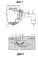
- Figure 1 shows diagrammatically the cross sectional view of the pressurized circulation lubrication system of an internal combustion engine, and an oil filter belonging to it and having been connected into the lubrication system of the engine with a device according to one embodiment of the invention;
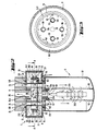
- Figure 2 shows the oil filter and device in figure 1;
- Figure 3 shows the cross sectional view A -A of the device in figure 2;
- Figure 4 shows a fixed device according to the invention which has been set in the main oil duct of the engine.
- Figure 5 shows diagrammatically as a partial longitudinal view an oil filter which has according to another embodiment of the invention been equipped with an electrical resistor and heat insulation;
- Figure 6 shows a cross sectional view B -B of an oil filter according to figure 5;
- Figure 7 shows diagrammatically as a partial longitudinal view an oil filter which has according to another embodiment of the invention been equipped with an electrical resistor inside the oil filter;
- As well known, pressurized circulation lubrication is nowadays commonly used in four-stroke engines. This is usually arranged in such a way that the so called
oil pan 2, the bottom of the crank case 1, functions as an oil tank from which the oil is sucked through astrainer 3 into the oil pump 4. After this the oil is forced through anoil filter 5 into themain oil duct 6, from where it passes along various oil ducts to lubricate the moving parts of the engine, such as the crank shaft, camshaft and valve gear. The various oil ducts in the engine are shown only referentially in figure 1, because their structure as such is not of any essence as far as the invention is concerned. The lubrication system of a diesel engine is, in principal, alike the one mentioned above. - Referring to figure 1 the
oil filter 5 has been mounted with thedevice 7 onto the wall of the crank case 1. Thedevice 7 is equipped with a least one heating resistor which is connected through theswitch 31 and/or thethermostat 32 to the source of current 30, for example a battery. Thesensor 33 of the thermostat is most advantageously set into thechamber 10 of thedevice 7 as shown in figure 2. The maximum temperature can be selected, and the thermostat controls that it is not exceeded. - The
oil filter 5 is in a known way cylindrically symmetrical by its structure and such that theinlets outlet 59, the orifices corresponding to the location of theinlet conduit 24 and theoutlet conduit 25 in the connectingpipes 34 of the engine. Inside theshell 51 of the oil filter there is acylindrical filter cartridge 52, through which the lubricating oil flows, while the engine is running, in the manner shown by arrows A in figure 2. - The
device 7 comprises achamber 10 which is advantageously formed between acylindrical jacket 8 and theflanges flanges tubular connectors flange 91, parallel with thejacket 8, and the second outwards, respectively. The inner surface of thefirst connector 11 hasfemale threads 11a, which match themale threads 34a, meant for theoil filter 5, in the connectingpipes 34 of the engine lubrication circuit. Respectively, there aremale threads 12a on the outer surface of thesecond connector 12 which match thefemale threads 53a on the inner surface of theconnector 53 of theoil filter 5. The inlet andoutlet conduits 121, 111 pass through theconnectors chamber 10 of thedevice 7 and out. Theflange 91 of thedevice 7 is, in addition, equipped with arubber gasket ring 231 on the side of the connectingpipes 34, as also theoil filter 5 is equipped with agasket ring 232. Thedevice 7 is equipped withconduits jacket 8, through thechamber 10 in thedevice 7. Theconduit connectors oil inlet conduits 24 and theinlets oil filter 5 in the adjoining area of the filter in question. The oil is forced through theconduits oil filter 5. - In the
chamber 10 inside thejacket 8 of thedevice 7 there is housed aflow guide 14, which is installed in a direction deviating from that of the inlet and/oroutlet conduit 121, 111. In this case it comprises a disc-shapedplate 141, set perpendicularly in relation to the conduits, and arim 142 belonging to it. Therim 142 is advantageously parallel with thejacket 8, and between it and thejacket 8 there is formed anannular duct 160. Between theplate 141 andsecond flange 92 there is formed the firstintermediate duct 15, and, respectively, between thecenter 141 and thefirst flange 91, there is formed the secondintermediate duct 17, through which intermediate ducts theconduits jacket 8. The flowthrough channel of the oil thus comprises theintermediate ducts small orifices 161 pierced through the peripheral area of thecenter 141, close to therim 142, through which a part of the oil also can flow. - The two
electrical resistors flow guide 14. The resistors are housed set inside thetubular parts rim 142 and circle aroundparts 142, whichparts resistors parts rim 142 of theflow guide 14 is achieved as effectively as possible. For this purpose, it is most advantageous to make thetubular parts rim 142 of theflow guide 14 of steel or another corresponding relatively highly heat conductive metal, and attach them to each other by welding, brazing or another such commonly known method. The disc-shapedplate 142 can also function, either entirely or partly, as a part of the element cooling the resistors and heating the oil. Theresistors conductor channel 22 to the source of current 30 as already explained in connection with figure 1. - A device according to the invention functions as follows. The
heating resistors switch 32 either manually or with an appropriate timing device. In thechamber 10 of thedevice 7 there is always a small amount, for example 2 desiliters, of oil, which start to heat up as an electrical current passes through theresistors thermostat 32 controls that the temperature of the oil does not exceed a desired level, for example 90°C, even if the waiting time were longer than estimated. This is especially important when theheating resistors - The warm oil contained by the
device 7 rushes, as soon as the engine is started, through the firstintermediate duct 15, mainly through theannular duct 160, and, to a small degree, through theorifices 161, and further through the secondintermediate duct 17 in the manner shown by the arrows B in figure 2, into theoutlet conduit 25 and directly into themain oil duct 6 of the engine or into a corresponding oil duct. The cold engine is thus immediately bathed in warm oil during its first revolutions; the resistance to revolution in the engine is essentially reduced, and the starting assured. - The time required for the heating of the oil depends, other than on the amount of oil, on the size of the resistor, on the construction of the cooling element for the resistors and on the construction of the flow guide, and especially on the extent of the efficient, i.e. heat conductive surface on the cooling element for the resistors, on the heat transfer between it and the resistor, and on the desired end temperature. Supposing that the amount of oil contained by the device and to be heated is 1 ... 2 desiliters and the construction of the flow guide is alike the one shown above (figures 2 and 3) and it functions entirely as a cooling device for the
resistors - In the embodiment of the device according to the invention shown above there is introduced one possibility for the carrying out of the
flow guide 14 and the resistor elements belonging to it. The object is, above all, to make the oil in thechamber 10 of thedevice 7 to be in contact with as large a surface as possible of the flow guide or the cooler element which forms an essential part of it, because it is with this that the heat produced by the resistors is ultimately conducted to the oil and the rising of the surface temperature of the element above the inflammation point of the oil prevented. It is economically most advantageous to construct the flow guide with its resistors as simple as possible. It can comprise a round or disc-shaped steel plate, onto the surface of which and onto the outer rim of which there are installed resistors on one or both sides. The flow guide can be made of any well heat conductive material. It can, when necessary, be sealed from thestraight conduits - According to one embodiment of the invention the heating element formed by the straight
tubular part 201 in which the resistors are housed, can be attached perpendicularly onto theflow guide 14 in such a way that it reaches through theoutlet 59 into the inside of theoil filter 5 into the center of thefilter cartridge 52. This is shown with a broke line is figure 2. Such an arrangement can be carried out either together with resistors set along the edge of the flow guide or in such a manner that there are no resistors attached onto the flow guide. Thetubular part 201 can be equipped with coolingflanges 202. - It must be noticed that the flow of oil through the
device 7 can be arranged in one direction only. Thus, for example, if the device is mounted in combination with the oil pump, the lubricating oil can be sucked through a separate passage into the oil pump and transferred through thedevice 7, equipped with the flow guide and resistors, directly into the main lubrication duct of the engine. In such a case, the device functions in the same manner as in the example of the application of the invention shown in figure 4, which will be referred to next. - Figure 4 shows diagrammatically how a device according to the invention can be built advantageously and fitted in as a fixed part of a new engine. The reference points in this figure are, as far as the device is concerned, mainly the same as in figure 2. The
main oil duct 6 is arranged to take a downwardsbend 61, and thechamber 10 is arranged into it. There are twoelectrical resistors chamber 10 with their cooling elements, thetubular parts rim 142 of theflow guide 14. The flow guide 14 has been set into thechamber 10 on a support such as thesleeve 143. The walls of the sleeve are appropriately equipped withorifices 162 so that the oil can flow in direction C through thechamber 10. - The device in figure 4 functions in the way already explained in connection with figure 2. The fitting of the
device 7 into thebend 61 fitted into themain oil duct 6 assures that the device is always full of oil after the engine has been turned off. The volume of thechamber 10 can thus be optimized according to the initial need of lubrication for the engine, most advantageously in the range of 1-3 desiliters. - The devices according to the invention described above can also be combined with some other device belonging to the lubrication circuit of the engine, such as for example the oil pump. The device can, in principle, be situated anywhere between the oil filter and/or the oil pump and the parts requiring lubrication in the engine. The precondition is that there is a direct and short connection from the device to the lubricating oil ducts of the engine. On the other hand, a fixed device according to the invention can be arranged into other ducts leading to important parts requiring lubrication in the engine, thus corresponding to the main oil duct, such as for example the oil duct delivering to the bearings of a turbo compressor. It is also advantageous to utilize a widening possibly already existing in the oil duct as the
oil chamber 10 of the device. - Figure 5 shows another embodiment of the device according to the invention, in which the oil filter is equipped with at least one electrical resistor and heat insulation. The
oil filter 5 is, by its construction, cylindrically symmetrical in a known way as in figure 2. - According to figure 5, there are two
electrical resistors oil filter 5 on its shell in such a way that the heating produced in them is transmitted as effectively as possible into thefilter 5 itself and from there into the oil contained by it. Theelectrical resistors example metal hoops 29 or metal strips 28. There is aninsulation 37 placed around theoil filter 5 and theelectrical resistors - The
insulation 37 comprises a dome-shaped 10-15 millimeter layer ofurethane 38, covered by a 2-4 millimeter hard-surface layer for shock-proofing, for example of polypropylethene. Theinsulation 38 may be permanently fixed around theoil filter 5, or it may be possible to change it and install it around the new filter during a filter change. - The
electrical resistors insulation 37 against theshell 51 of the oil filter. Between theconnector 53 of the oil filter and the connectingpipes 34 of the lubrication circuit there is fitted anintermediate piece 40 which is made of such material as plastic that conducts heat poorly. It thus prevents the appearing of heat leakages between thefilter 5 and the connectingpipes 34. At the same time, the intermediate piece functions as the support for theinsulation 37. - The
intermediate piece 40 is equipped with an annular duct corresponding to theoil inlet conduit 24 and with a tubular duct corresponding to theoil outlet conduit 25, situated in the middle of the annular one and isolated from it. The part 40a on the filter side of theintermediate piece 40 is equipped with male threads 41 which match thefemale fastening threads 53a of theconnector 53 of the oil filter, and thepart 40b on the side of the connectingpipes 34 of the intermediate piece is equipped withfemale threads 42, which match, correspondingly, themale fastening threads 34a meant for the filter in the connectingpipes 34 of the lubrication circuit. Thefemale threads 42 in the intermediate piece are arranged in ametal piece 43 which is cast inside a plastic intermediate piece. Theintermediate piece 40 is, in addition, equipped with arubber gasket ring - The dome-shaped
insulation 37 and theintermediate piece 40 can be made into either a fixed unit or a detachable one. In figure 5'there is shown the latter alternative, theinsulation 37 is fastened withthreads 46 onto theintermediate piece 40. - Intermediate pieces between the oil filter and the lubrication circuit of the engine, such as described above, can be used as fitting members for for example the fitting of a filter bigger than normal into the lubrication circuit. The one end of the intermediate piece, onto which the filter is to be attached, may for example in diameter be larger than the on previously used and threaded in such a way that some other oil filter which is fit for the purpose and commercially available, can be attached to it. Thus for example in engines of considerable size and heavy duty machines the regular oil filter may be replaced by an oil filter which is, in relation, 1,5-4 times larger in volume, and it can be equipped with heat insulation. This alternative assures the sufficiency of hot lubricating oil and the success of the cold starting.
- In the example of function according to figure 5, the size of the
first resistor 26 is determined in such a way that the heat energy given by it is in the same range as the heat leakage in theinsulation 37. Thus the heat energy given by the resistor suffices to retain the temperature of the filter and the oil in it on a level at least 20°-30°C higher than that of the surroundings. The size of the second of theresistor 27 can be determined in such a way that the temperature of the oil contained by theoil filter 5 can be brought up to a certain temperature in a desired amount of time. Because the amount of oil in thefilter 5 is, generally, in the range of 2-6 desiliters and the heat leakages minimal especially with the arrangements shown above, theresistors battery 30, of an automobile or duty machine, without straining the battery too much. - The
electrical resistors switch 31 a or with thethermostat oil filter 5 or onto its shell as shown in figure 5. The desired maximum temperature can be selected and the thermostat controls that it is not exceeded. In addition, theswitch 31 b, controlled by a timing device, can be used, in which case for example the heating can be started at the desired moment before the starting of the engine. - A device according to figure 5 operates as follows. When the automobile is left, on a cold evening, standing by the curb for the night, the
first resistor 26 is connected with theswitch 31a a to the battery, and thesecond resistor 27 is set with the clock-controlledswitch 31 b to connect to the battery for example 3 hours before the starting in the morning. Thus the temperature of the oil in the oil filter remains, by the agency of the first resistor, almost constant into the small hours of the morning, when the second resistor switches on. The lubricating oil in theoil filter 5 now heats, during a period of a few hours, up to a certain temperature, for example 90°C. Thethermostat oil filter 5 by the agency of the main oil duct of the engine to the sleeve bearing, and the resistance to revolution in the engine is considerably reduced. - The electrical resistor or resistors can also be made to form a
tubular heating element 201 housed inside the oil filter, most advantageously in the center of it, for example in the center of the filter cartridge, and be fixed in the center of the orifices in the intermediate piece, as shown with the broken line in figure 5. Another possibility is to mount theheating element 201 in theoil filter 5, for example, according to figure 6. - In the embodiment of figure 6 the
oil filter 5 is equipped with aconnector 203 having female threads. The tubular heating resistor comprises aconnector 204 having male thread. So theheating element 201 can be screwed into its position inside the oil filter. - The layer of oil between the heating element and the surface of the filter and/or the filter cartridge in figure 6 functions in a manner corresponding to that of the
insulation 37 described above. In such a case it is, deviating from solutions shown before, advantageous to use one or more electrical resistors, the total output of which is in the range of 50-200 W. The resistor or resistors can, because of their relatively considerable output, be connected to the battery only 15-30 minutes before the starting. The connecting can be done either with a timing device or manually with a separate switch. The thermostat is necessary also in this case in order to prevent overheating. A normal battery in good condition will well tolerate a short heavy loading of this kind. - The intermediate piece can also be made a shape different from what has been shown above. The essential is that when an intermediate piece is used, it can be connected to those connecting pipes in the lubrication circuit of the engine which are meant for the oil filter, and, on the other hand, that the desired oil filter, in turn, can be connected to the intermediate piece. This embodiment of the invention is close to the solution shown with the broken line in figure 2, with the difference that the separate device is replaced by an intermediate piece equipped with flow-through channels. The corresponding remarks on the possibilities for the connecting of the intermediate piece are valid of the
separate device 7 also.
Claims (10)
characterized in that
Priority Applications (1)
| Application Number | Priority Date | Filing Date | Title |
|---|---|---|---|
| AT84900056T ATE37215T1 (en) | 1982-12-07 | 1983-12-07 | DEVICE FOR IMPROVING THE STARTING OF AN ENGINE. |
Applications Claiming Priority (6)
| Application Number | Priority Date | Filing Date | Title |
|---|---|---|---|
| FI823746 | 1982-12-07 | ||
| FI823746A FI66059C (en) | 1982-12-07 | 1982-12-07 | ANORDING FOER FOERBAETTRANDE AV EN FOERBRAENNINGSMOTORS KALLSTART |
| FI8300039 | 1983-05-04 | ||
| WOPCT/FI83/00039 | 1983-05-04 | ||
| FI832963 | 1983-08-18 | ||
| FI832963A FI71604C (en) | 1983-08-18 | 1983-08-18 | TILLSATSANORDNING FOER FOERBAETTRANDE AV STARTEN AV EN MOTOR. |
Publications (2)
| Publication Number | Publication Date |
|---|---|
| EP0128178A1 EP0128178A1 (en) | 1984-12-19 |
| EP0128178B1 true EP0128178B1 (en) | 1988-09-14 |
Family
ID=27241077
Family Applications (1)
| Application Number | Title | Priority Date | Filing Date |
|---|---|---|---|
| EP84900056A Expired EP0128178B1 (en) | 1982-12-07 | 1983-12-07 | A device for the improving of the starting of an engine |
Country Status (6)
| Country | Link |
|---|---|
| US (1) | US4522166A (en) |
| EP (1) | EP0128178B1 (en) |
| DE (1) | DE3390405T1 (en) |
| NO (1) | NO843138L (en) |
| SE (1) | SE450844B (en) |
| WO (1) | WO1984002377A1 (en) |
Families Citing this family (26)
| Publication number | Priority date | Publication date | Assignee | Title |
|---|---|---|---|---|
| US4790938A (en) * | 1986-01-24 | 1988-12-13 | Younger Gilbert W | Filter for removing particulate matter from fluid within a movable body |
| US4831980A (en) * | 1987-07-13 | 1989-05-23 | Toyo Radiator Co., Ltd. | Oil cooler assembly with integrated oil filter for internal combustion engine |
| US4925553A (en) * | 1988-11-18 | 1990-05-15 | John H. Cox, III | Pressurized oil filter/carbon separator |
| US4971704A (en) * | 1989-09-05 | 1990-11-20 | Electrolube Devices, Inc. | System for purifying engine lubricating oil |
| EP0530685B1 (en) * | 1991-09-04 | 1997-04-23 | Koyo Seiko Co., Ltd. | Oil tank |
| WO1995026461A1 (en) * | 1994-03-29 | 1995-10-05 | Orbital Engine Company (Australia) Pty. Limited | Pump control system |
| DE19645943A1 (en) * | 1996-11-07 | 1998-05-14 | Bosch Gmbh Robert | Starter unit for an internal combustion engine |
| DE19847533A1 (en) * | 1998-10-15 | 2000-04-20 | Zf Batavia Llc | Pressurised oil system, especially for motor vehicles has pump, oil filter, pressure line, oil sump and suction tube with suction funnel, one which can be electrically heated |
| US6198249B1 (en) | 2000-02-15 | 2001-03-06 | Mark W. Kroll | Thermal booster battery system |
| US6746600B2 (en) | 2001-10-31 | 2004-06-08 | Arvin Technologies, Inc. | Fluid filter with integrated cooler |
| ITRE20040066A1 (en) * | 2004-06-01 | 2004-09-01 | Ufi Filters Spa | IMPROVED FILTER GROUP FOR ENDOTHERMAL DIESEL ENGINES |
| US8186160B2 (en) * | 2009-03-02 | 2012-05-29 | Michael Anthony | Thermal engine for operation with combustible and noncombustible fuels and electric energy |
| DE102009028326A1 (en) * | 2009-08-07 | 2011-02-10 | Robert Bosch Gmbh | Method and device for heating engine and transmission oil of a hybrid vehicle |
| US8590516B2 (en) * | 2009-10-02 | 2013-11-26 | Robert Hull | Internal combustion engine |
| DE102011075666B4 (en) * | 2011-05-11 | 2018-07-12 | Ford Global Technologies, Llc | Method for heating the engine oil of an internal combustion engine and internal combustion engine for carrying out such a method |
| RU2478822C1 (en) * | 2011-12-08 | 2013-04-10 | Федеральное государственное бюджетное образовательное учреждение высшего профессионального образования "Пензенская государственная сельскохозяйственная академия" | Combined fuel filter |
| RU2503845C1 (en) * | 2012-11-28 | 2014-01-10 | Сергей Анатольевич Бублий | Device to start ice with dry crankcase at negative ambient temperatures |
| US9494279B2 (en) * | 2014-10-21 | 2016-11-15 | Toyota Motor Engineering & Manufacturing North America, Inc. | Vehicle oil pan with active noise reduction control |
| DE102016201609A1 (en) * | 2016-02-03 | 2017-08-03 | Mahle International Gmbh | Engine system |
| CN110573818B (en) * | 2017-05-11 | 2021-10-08 | 沃尔沃卡车集团 | Heat exchanger device |
| RU2680908C2 (en) * | 2017-06-08 | 2019-02-28 | Российская Федерация, от имени которой выступает Министерство промышленности и торговли Российской Федерации (Минпромторг России) | Method of automated loading of ship internal combustion engine |
| DE102017217491A1 (en) | 2017-09-29 | 2019-04-04 | Mahle International Gmbh | Line filter device |
| US10844760B2 (en) * | 2018-01-30 | 2020-11-24 | Cumming Power Generation IP, Inc. | Oil heater for a generator set |
| DE102019204369A1 (en) * | 2019-03-28 | 2020-10-01 | Zf Friedrichshafen Ag | Method for improving the low temperature behavior of an electric or hybrid vehicle |
| CN110307055A (en) * | 2019-06-28 | 2019-10-08 | 广西玉柴机器股份有限公司 | A kind of oil filter with heating device |
| CN113006899B (en) * | 2021-03-24 | 2022-08-30 | 安徽江淮汽车集团股份有限公司 | Engine oil heating device and automobile |
Citations (4)
| Publication number | Priority date | Publication date | Assignee | Title |
|---|---|---|---|---|
| US3235084A (en) * | 1962-01-30 | 1966-02-15 | Stewart Warner Corp | Fuel filter with heating unit |
| US3463317A (en) * | 1967-08-07 | 1969-08-26 | Walter R Prier | Adapter unit for a fluid filter and a fluid cooler |
| DE2845520A1 (en) * | 1978-10-19 | 1980-05-08 | Bosch Gmbh Robert | Filter esp. for diesel fuel incorporating heat exchanger - can be assembled as filter only or complete unit |
| US4321136A (en) * | 1979-06-21 | 1982-03-23 | Nissan Motor Co., Ltd. | Fuel filtering device for engine |
Family Cites Families (10)
| Publication number | Priority date | Publication date | Assignee | Title |
|---|---|---|---|---|
| US2088243A (en) * | 1936-11-21 | 1937-07-27 | Koinzan Walter | Oil filter |
| DE2115221A1 (en) * | 1971-03-30 | 1972-10-05 | Fervers, Roland, Dipl.-Ing., 4300 Essen | Device for heating the engine of vehicles |
| US3915860A (en) * | 1973-12-26 | 1975-10-28 | Glen R Priest | Oil reconditioning device |
| JPS5554619A (en) * | 1978-10-16 | 1980-04-22 | Toyota Motor Corp | Oil filter capable of warming lubricating oil promptly |
| IE800262L (en) * | 1980-02-12 | 1981-08-12 | Julio Gascon Losa D | Engine lubricating oil purification |
| IT8053035V0 (en) * | 1980-03-17 | 1980-03-17 | Fabio Sciascia | HEATER DEVICE APPLICABLE ON A FUEL FILTER |
| AU7077181A (en) * | 1980-08-11 | 1982-03-02 | Masso, J.I. | Oil refining apparatus |
| US4354946A (en) * | 1981-07-22 | 1982-10-19 | Frank M. Warlick | Oil reconditioning apparatus and method |
| US4369110A (en) * | 1981-08-13 | 1983-01-18 | David L. Priest | Oil filter for use on internal combustion engines |
| US4388185A (en) * | 1982-04-26 | 1983-06-14 | Norman Ott | Electric oil refiner |
-
1983
- 1983-12-06 US US06/558,423 patent/US4522166A/en not_active Expired - Fee Related
- 1983-12-07 WO PCT/FI1983/000078 patent/WO1984002377A1/en active IP Right Grant
- 1983-12-07 DE DE19833390405 patent/DE3390405T1/en not_active Withdrawn
- 1983-12-07 EP EP84900056A patent/EP0128178B1/en not_active Expired
-
1984
- 1984-08-01 SE SE8403946A patent/SE450844B/en not_active Application Discontinuation
- 1984-08-06 NO NO843138A patent/NO843138L/en unknown
Patent Citations (4)
| Publication number | Priority date | Publication date | Assignee | Title |
|---|---|---|---|---|
| US3235084A (en) * | 1962-01-30 | 1966-02-15 | Stewart Warner Corp | Fuel filter with heating unit |
| US3463317A (en) * | 1967-08-07 | 1969-08-26 | Walter R Prier | Adapter unit for a fluid filter and a fluid cooler |
| DE2845520A1 (en) * | 1978-10-19 | 1980-05-08 | Bosch Gmbh Robert | Filter esp. for diesel fuel incorporating heat exchanger - can be assembled as filter only or complete unit |
| US4321136A (en) * | 1979-06-21 | 1982-03-23 | Nissan Motor Co., Ltd. | Fuel filtering device for engine |
Also Published As
| Publication number | Publication date |
|---|---|
| SE450844B (en) | 1987-08-03 |
| DE3390405T1 (en) | 1985-01-24 |
| EP0128178A1 (en) | 1984-12-19 |
| SE8403946D0 (en) | 1984-08-01 |
| US4522166A (en) | 1985-06-11 |
| NO843138L (en) | 1984-08-06 |
| WO1984002377A1 (en) | 1984-06-21 |
| SE8403946L (en) | 1984-08-01 |
Similar Documents
| Publication | Publication Date | Title |
|---|---|---|
| EP0128178B1 (en) | A device for the improving of the starting of an engine | |
| US4372260A (en) | Engine fluid heater | |
| US6340006B1 (en) | Internal combustion engines having separated cooling circuits for the cylinder head and the engine block | |
| US7481187B2 (en) | System and method for supplying auxiliary power to a large diesel engine | |
| US20040118764A1 (en) | Multiple fuel filter pump module | |
| US5249623A (en) | Rubber heat exchanger | |
| US5662072A (en) | Engine warming-up apparatus for a vehicle and heat insulating device | |
| US4865005A (en) | Diesel fuel heater | |
| EP0681673A1 (en) | Power fluid heating system | |
| WO1988005123A1 (en) | Marine propulsion auxiliary cooling system | |
| US2122585A (en) | Heating apparatus for the oil in the crankcase and water in the cooling system of internal combustion engines | |
| US4768580A (en) | Marine propulsion device oil cooling arrangement | |
| RU2145286C1 (en) | Automobile drive set | |
| US6601571B1 (en) | System for vaporizing liquefied petrol gas heated by engine lubricating oil | |
| RU2109148C1 (en) | Combination system of automatic control and regulation of internal combustion engine thermal conditions | |
| AU2332184A (en) | A device for the improving of the starting of an engine | |
| EP1339981B1 (en) | System and method for supplying auxiliary power to a large diesel engine | |
| EP0183343B1 (en) | Fuel tank heating system | |
| US11614023B2 (en) | Control valve | |
| FI71604B (en) | TILLSATSANORDNING FOER FOERBAETTRANDE AV STARTEN AV EN MOTOR | |
| US2712815A (en) | Electrically actuated fluid heating attachment for automotive engines | |
| US3550725A (en) | Oil cooling system for internal combustion engines | |
| FI66059B (en) | ANORDING FOER FOERBAETTRANDE AV EN FOERBRAENNINGSMOTORS KALLSTART | |
| CA1234321A (en) | Apparatus for heating liquid fuel and lubricating oil of an internal combustion engine | |
| FI74524C (en) | FOERFARANDE OCH APPARATUR FOER UPPVAERMNING AV KYLVAETSKA FOER FOERBRAENNINGSMOTOR. |
Legal Events
| Date | Code | Title | Description |
|---|---|---|---|
| PUAI | Public reference made under article 153(3) epc to a published international application that has entered the european phase |
Free format text: ORIGINAL CODE: 0009012 |
|
| 17P | Request for examination filed |
Effective date: 19840903 |
|
| AK | Designated contracting states |
Kind code of ref document: A1 Designated state(s): AT BE CH DE FR GB LI LU NL SE |
|
| GRAA | (expected) grant |
Free format text: ORIGINAL CODE: 0009210 |
|
| AK | Designated contracting states |
Kind code of ref document: B1 Designated state(s): AT BE CH DE FR GB LI LU NL SE |
|
| PG25 | Lapsed in a contracting state [announced via postgrant information from national office to epo] |
Ref country code: NL Effective date: 19880914 Ref country code: FR Free format text: THE PATENT HAS BEEN ANNULLED BY A DECISION OF A NATIONAL AUTHORITY Effective date: 19880914 Ref country code: BE Effective date: 19880914 |
|
| REF | Corresponds to: |
Ref document number: 37215 Country of ref document: AT Date of ref document: 19880915 Kind code of ref document: T |
|
| REF | Corresponds to: |
Ref document number: 3377992 Country of ref document: DE Date of ref document: 19881020 |
|
| PG25 | Lapsed in a contracting state [announced via postgrant information from national office to epo] |
Ref country code: GB Effective date: 19881207 |
|
| PG25 | Lapsed in a contracting state [announced via postgrant information from national office to epo] |
Ref country code: LU Free format text: LAPSE BECAUSE OF NON-PAYMENT OF DUE FEES Effective date: 19881231 |
|
| EN | Fr: translation not filed | ||
| NLV1 | Nl: lapsed or annulled due to failure to fulfill the requirements of art. 29p and 29m of the patents act | ||
| PLBE | No opposition filed within time limit |
Free format text: ORIGINAL CODE: 0009261 |
|
| STAA | Information on the status of an ep patent application or granted ep patent |
Free format text: STATUS: NO OPPOSITION FILED WITHIN TIME LIMIT |
|
| 26N | No opposition filed | ||
| GBPC | Gb: european patent ceased through non-payment of renewal fee | ||
| PGFP | Annual fee paid to national office [announced via postgrant information from national office to epo] |
Ref country code: AT Payment date: 19891122 Year of fee payment: 7 |
|
| PGFP | Annual fee paid to national office [announced via postgrant information from national office to epo] |
Ref country code: CH Payment date: 19891127 Year of fee payment: 7 |
|
| PGFP | Annual fee paid to national office [announced via postgrant information from national office to epo] |
Ref country code: SE Payment date: 19891214 Year of fee payment: 7 |
|
| PGFP | Annual fee paid to national office [announced via postgrant information from national office to epo] |
Ref country code: DE Payment date: 19891228 Year of fee payment: 7 |
|
| PG25 | Lapsed in a contracting state [announced via postgrant information from national office to epo] |
Ref country code: AT Effective date: 19901207 |
|
| PG25 | Lapsed in a contracting state [announced via postgrant information from national office to epo] |
Ref country code: SE Effective date: 19901208 |
|
| PG25 | Lapsed in a contracting state [announced via postgrant information from national office to epo] |
Ref country code: LI Effective date: 19901231 Ref country code: CH Effective date: 19901231 |
|
| REG | Reference to a national code |
Ref country code: CH Ref legal event code: PL |
|
| PG25 | Lapsed in a contracting state [announced via postgrant information from national office to epo] |
Ref country code: DE Effective date: 19910903 |
|
| EUG | Se: european patent has lapsed |
Ref document number: 84900056.7 Effective date: 19910910 |