EP0128463A2 - Space heating apparatus for small spaces - Google Patents
Space heating apparatus for small spaces Download PDFInfo
- Publication number
- EP0128463A2 EP0128463A2 EP84106191A EP84106191A EP0128463A2 EP 0128463 A2 EP0128463 A2 EP 0128463A2 EP 84106191 A EP84106191 A EP 84106191A EP 84106191 A EP84106191 A EP 84106191A EP 0128463 A2 EP0128463 A2 EP 0128463A2
- Authority
- EP
- European Patent Office
- Prior art keywords
- heat exchanger
- heater according
- flame tube
- jacket
- open
- Prior art date
- Legal status (The legal status is an assumption and is not a legal conclusion. Google has not performed a legal analysis and makes no representation as to the accuracy of the status listed.)
- Granted
Links
Images
Classifications
-
- F—MECHANICAL ENGINEERING; LIGHTING; HEATING; WEAPONS; BLASTING
- F24—HEATING; RANGES; VENTILATING
- F24H—FLUID HEATERS, e.g. WATER OR AIR HEATERS, HAVING HEAT-GENERATING MEANS, e.g. HEAT PUMPS, IN GENERAL
- F24H3/00—Air heaters
- F24H3/02—Air heaters with forced circulation
- F24H3/06—Air heaters with forced circulation the air being kept separate from the heating medium, e.g. using forced circulation of air over radiators
- F24H3/065—Air heaters with forced circulation the air being kept separate from the heating medium, e.g. using forced circulation of air over radiators using fluid fuel
-
- F—MECHANICAL ENGINEERING; LIGHTING; HEATING; WEAPONS; BLASTING
- F24—HEATING; RANGES; VENTILATING
- F24C—DOMESTIC STOVES OR RANGES ; DETAILS OF DOMESTIC STOVES OR RANGES, OF GENERAL APPLICATION
- F24C1/00—Stoves or ranges in which the fuel or energy supply is not restricted to solid fuel or to a type covered by a single one of the following groups F24C3/00 - F24C9/00; Stoves or ranges in which the type of fuel or energy supply is not specified
- F24C1/14—Radiation heating stoves and ranges, with additional provision for convection heating
Definitions
- the invention relates to a space heater for small spaces, in particular for mobile spaces, such as caravans, vehicle and ship cabins or the like, according to the preamble of claim 1.
- the heat exchanger together with its heating surfaces on both sides is made from a single die-cast or injection-molded piece. It consists of a tube with a circular cross-section, from which inner and outer fins protrude as indirect heating surfaces. At one end, this heat exchanger is closed off by an approximately spherical cap, while at the other open end there is the combustion chamber, from which a cylindrical flame tube projects into the heat exchanger. This flame tube, which is perforated along its entire length, ends at a noticeable distance from the heat exchanger cap and a noticeable distance is kept between it and the inner fin tips.
- a heat exchanger cylinder with fins protruding inside and outside requires relatively large diameters. If many slats are provided for high performance, a complicated fitting is created. The fins essentially only act like indirect heating surfaces with relatively long passageways, while the remaining surfaces are very small for direct heat transfer.
- the invention is therefore based on the object of providing an improved heat exchanger for a heater of the aforementioned type which can be produced in a simple manner and which can be produced by a particularly high specific heating excellence.
- This heat exchanger is suitable both for the direct heating of the room air if it is used as a free heat exchanger in a heater that can be set up as well as in connection with a boiler room jacket, which then surrounds the heat exchanger at a suitable distance and expediently at full height. To increase the flow tion and thus the heating power, this hot air flow can still be acted upon by a blower.
- a burner 2 which is not described in more detail, in a combustion chamber 1.
- This flame tube extends upwards in the interior of a heat exchanger 10, where it ends with its upper outlet opening 5 shortly before a ceiling surface 23 of the heat exchanger.
- a protective plate 7 is placed on the flame tube, which protects the heat exchanger top surface 23 from overheating.
- the flame tube is formed from a suitable and appropriately surface-treated sheet metal blank, at least one expansion fold (not visible) being expediently formed along a surface line to absorb thermal expansions that occur.
- the heat exchanger 10 expediently a shaped piece made of an aluminum alloy, forms an annular space 11 at its open end through a base cylinder 13.
- a base collar 14 can also be designed to hold the heat exchanger on a base attachment (not shown).
- An outlet connection 12 leads from the annular space 11 for the extraction of the combustion gases to the outside.
- the heat exchanger is formed by a wave jacket 15. This consists of evenly running around the circumference Waves 16, the outer wave crests 18 and inner wave valleys 17 each lie on an imaginary circle.
- the shaft walls 19, which delimit the inwardly open shaft channels 20, are approximately parallel to one another.
- the combustion gases flow downwards after exiting the flame tube and deflected at the ceiling surface 23, where they are taken up by the annular space 11 and finally discharged to the outside through the outlet connection 12.
- the inner ren wave channels 20 are closed at the top by deflecting walls 25, which slope obliquely outwards and thereby form favorable deflecting surfaces for the combustion gases.
- the annular space 11 formed by the base cylinder 13 is delimited on the outside by the transition walls 26.
- the flame tube lies directly on the inner surfaces of the shafts 16, the heat is transferred directly from the flame tube to the heat exchanger.
- the flame tube 3 adjacent to the wave troughs 17 closes off these wave channels, so that the combustion gases are divided into a large number of individual streams, which fall down in the form of relatively narrow flow layers and are surrounded by relatively large heating surfaces. In this way, there is a very even distribution of the combustion gases and thus also a uniform heat emission over the entire extent of the heat exchange. shers.
- the annular space 11 acts here as a collecting space for the falling combustion gases and thus ensures their undisturbed extraction, even if there is only one outlet connection at one point.
- the heat exchanger according to the invention can or the like without a housing jacket. Cladding are set up and act directly on the room air, which flows up and warms up along its outer shaft channels 21. A more powerful device can be used in conjunction with reach a heating chamber jacket 28 which expediently surrounds the heat exchanger at full height and at a short distance from the wave crests 18. An air inlet opening 29 at the level of the annular space 11 allows sufficient air access, a slight expansion 31 of the heating chamber jacket in the lower area ensuring a uniform distribution of the inflowing air around the heat exchanger. Above the heat exchanger, the heating chamber jacket is brought together to form an air outlet opening 30, from which the hot air can either flow directly into the room to be heated or flow into a pipe system.
- the invention is not limited to the illustrated embodiment.
- a precisely cylindrical arrangement of the heat exchanger shaft jacket 15 and / or of the flame tube 3 is also possible, although a predetermined conicity, which takes into account the gas concentration due to cooling and thereby avoids a flow delay, has a more advantageous effect.
- the jacket shafts do not necessarily have to extend over the entire length of the heat exchanger, which can be the case, for example, if they can only start in an upper region due to a different design of the combustion chamber and / or the hot air duct. If, in the illustrated heat exchanger, the jacket shafts line up in close succession, this includes a different design with e.g. wider wave valleys and / or mountains, which can also be different, not.
Abstract
Bei einem Raumheizgerät für Kleinräume, insbesondere für fahrbare Räume, wird ein etwa zylindrischer Wärmetauscher (10) auf einem Großteil seiner Länge von einem Wellenmantel (15) gebildet, wobei diese Mantelwellen (16) auf den Mantelumfang verteilte, längsgerichtete innere und äußere Wellenkanäle (20, 21) bilden, in denen die Verbrennungsgase bzw. die zu erwärmende Heißluft geführt sind.In the case of a space heater for small rooms, in particular for mobile rooms, an approximately cylindrical heat exchanger (10) is formed over a large part of its length by a corrugated sheath (15), these sheathed shafts (16) being distributed on the circumference of the sheath, longitudinal inner and outer corrugated channels (20 , 21) form in which the combustion gases or the hot air to be heated are guided.
Description
Die Erfindung betrifft ein Raumheizgerät für Kleinräume, insbesondere für fahrbare Räume, wie Wohnwagen, Fahrzeug-und Schiffskabinen od. dgl., gemäß dem Oberbegriff des Patentanspruches 1.The invention relates to a space heater for small spaces, in particular for mobile spaces, such as caravans, vehicle and ship cabins or the like, according to the preamble of
Bei einem Raumheizgerät dieser Art (DE-OS 21 39 504) ist der Wärmetauscher mitsamt seinen beidseitigen Heizflächen aus einem einzigen Druckguß- bzw. Spritzgußstück hergestellt. Er besteht aus einem im Querschnitt kreisrunden Rohr, von dem innere und äußere Lamellen als indirekte Heizflächen abstehen. An einem Ende ist dieser Wärmetauscher durch eine etwa kugelförmige Kappe abgeschlossen, während sich am anderen offenen Ende die Brennkammer befindet, von der ein zylindrisches Flammrohr in den Wärmetauscher hineinragt. Dieses auf seiner ganzen Länge mit Wanddurchbrechungen versehene Flammrohr endet in einem merklichen Abstand von der Wärmetauscherkappe und zwischen ihm und den inneren Lamellenspitzen ist ein merklicher Abstand freigehalten. Ein Wärmetauscherzylinder mit innen und außen abstehenden Lamellen erfordert verhältnismäßig große Durchmesser. Werden für eine hohe Leistung viele Lamellen vorgesehen, entsteht ein kompliziertes Formstück. Die Lamellen wirken im wesentlichen nur wie indirekte Heizflächen mit verhältnismäßig langen Durchgangswegen, während die verbleibenden Flächen für einen direkten Wärmedurchgang sehr klein sind.In a room heater of this type (DE-OS 21 39 504), the heat exchanger together with its heating surfaces on both sides is made from a single die-cast or injection-molded piece. It consists of a tube with a circular cross-section, from which inner and outer fins protrude as indirect heating surfaces. At one end, this heat exchanger is closed off by an approximately spherical cap, while at the other open end there is the combustion chamber, from which a cylindrical flame tube projects into the heat exchanger. This flame tube, which is perforated along its entire length, ends at a noticeable distance from the heat exchanger cap and a noticeable distance is kept between it and the inner fin tips. A heat exchanger cylinder with fins protruding inside and outside requires relatively large diameters. If many slats are provided for high performance, a complicated fitting is created. The fins essentially only act like indirect heating surfaces with relatively long passageways, while the remaining surfaces are very small for direct heat transfer.
Der Erfindung liegt daher die Aufgabe zugrunde, für ein Heizgerät vorgenannter Art einen verbesserten Wärmetauscher zu schaffen, der sich in einfacher Weise herstellen läßt und sich durch eine besonders hohe spezifische Heizleistung auszeichnet.The invention is therefore based on the object of providing an improved heat exchanger for a heater of the aforementioned type which can be produced in a simple manner and which can be produced by a particularly high specific heating excellence.
Diese Aufgabe wird mit einem Heizgerät von der im Oberbegriff des Patentanspruches 1 genannten Art gemäß der Erfindung durch die kennzeichnenden Merkmale dieses Patentanspruches gelöst.This object is achieved with a heater of the type mentioned in the preamble of
Bei einem erfindungsgemäß ausgebildeten Wärmetauscher, in dem die Verbrennungsgase und die zu erwärmende Heizluft in Wellenkanälen geführt werden, wird nicht nur ein intensiver Wärmeübergang erreicht, sondern es erfolgt auch eine gleichmäßige Erwärmung rund um den Wärmetauscher, weil die Verbrennungsgase gleichmäßig auf die Wellenkanäle aufgefächert werden und in diesen Kanälen unter gleichen Bedingungen entlangströmen. Durch die Vielzahl der Mantelwellen wird die aktive Heizfläche erheblich vergrößert und die beiden gegeneinander strömenden Medien sind lediglich durch die dünne Wellenwand voneinander getrennt, so daß optimale Wärmedurchgangsverhältnisse gegeben sind. Dies ermöglicht für eine angestrebte Heizleistung eine merkliche Verkleinerung des Wärmetauschers.In the case of a heat exchanger designed according to the invention, in which the combustion gases and the heating air to be heated are guided in wave channels, not only is an intensive heat transfer achieved, but there is also uniform heating around the heat exchanger because the combustion gases are spread out evenly on the wave channels and flow along in these channels under the same conditions. Due to the large number of jacket waves, the active heating surface is considerably enlarged and the two media flowing against each other are only separated from each other by the thin wall of the wave, so that optimal heat transfer conditions are given. This enables a noticeable reduction in the size of the heat exchanger for a desired heating output.
Liegt das Flammrohr an den Innenflächen der Mantelwellen direkt an, dann erfolgt bereits dadurch ein Aufheizen der Mantelwellen. Dieses anliegende Flammrohr schließt ferner die Wellenkanäle gegeneinander ab, so daß zahlreiche getrennte Strömungsschächte vorhanden sind, in denen die Verbrennungsgasströme von kleinem Querschnitt an drei Seiten von wärmeabgebenden Heizflächen umgeben sind und dadurch in höchstem Maße den Verbrennungsgasen Wärme entzogen wird.If the flame tube is in direct contact with the inner surfaces of the jacket shafts, this already heats up the jacket shafts. This adjacent flame tube also closes off the shaft channels from one another, so that numerous separate flow shafts are present, in which the combustion gas streams of small cross-section are surrounded on three sides by heat-emitting heating surfaces and, as a result, heat is extracted from the combustion gases to the highest degree.
Dieser Wärmetauscher eignet sich sowohl zur direkten Erwärmung der Raumluft, wenn er als freier Wärmetauscher in einem entsprechend aufstellbaren Heizgerät Verwendung findet, als auch in Verbindung mit einem Heizraummantel, der den Wärmetauscher dann in geeignetem Abstand und zweckmäßig in voller Höhe umschließt. Zur Steigerung der Strömung und damit der Heizleistung kann dieser Heißluftstrom noch durch ein Gebläse beaufschlagt sein.This heat exchanger is suitable both for the direct heating of the room air if it is used as a free heat exchanger in a heater that can be set up as well as in connection with a boiler room jacket, which then surrounds the heat exchanger at a suitable distance and expediently at full height. To increase the flow tion and thus the heating power, this hot air flow can still be acted upon by a blower.
Die Erfindung wird nachfolgend anhand eines Ausführungsbeispiels, das auch in der Zeichnung schematisiert dargestellt ist, näher beschrieben. Es zeigen:
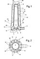
- Fig. 1 einen Vertikalschnitt durch ein einfaches Heizgerät, bei dem die Leitungs- und Gehäuseanschlüsse weggelassen sind und
- Fig. 2 einen Horizontalschnitt nach der Linie II-II durch den Wärmetauscher der Fig. 1.
- Fig. 1 shows a vertical section through a simple heater, in which the line and housing connections are omitted and
- 2 is a horizontal section along the line II-II through the heat exchanger of FIG. 1st
In dem vereinfacht dargestellten Raumheizgerät befindet sich in einer Brennkammer 1 ein nicht näher beschriebener Brenner 2. Ein Flammrohr ist mit seinem Aufsteckende 8 auf diesen Brenner 2 aufgesetzt. Dieses Flammrohr erstreckt sich im Innern eines Wärmetauschers 10 nach oben, wo es mit seiner oberen Austrittsöffnung 5 kurz vor einer Deckenfläche 23 des Wärmetauschers endet. Mittels Stützen 6 ist auf das Flammrohr noch eine Schutzplatte 7 aufgesetzt, die die Wärmetauscher-Deckenfläche 23 vor überhitzung schützt. Das Flammrohr ist aus einem geeigneten und entsprechend oberflächenbehandelten Blechzuschnitt geformt, wobei zweckmäßigerweise mindestens eine Dehnungsfalte (nicht sichtbar) entlang einer Mantellinie zum Auffangen auftretender Wärmedehnungen ausgebildet ist.In the space heater, shown in simplified form, there is a burner 2, which is not described in more detail, in a
Der Wärmetauscher 10, zweckmäßig ein Formstück aus einer Aluminiumlegierung, bildet an seinem offenen Ende durch einen Sockelzylinder 13 einen Ringraum 11. Ein Sockelbund 14 kann noch zur Halterung des Wärmetauschers auf einer Bodenbefestigung (nicht dargestellt) ausgebildet sein. Vom Ringraum 11 führt ein Austrittsstutzen 12 für den Abzug der Verbrennungsgase nach außen. Der Wärmetauscher wird von einem Wellenmantel 15 gebildet. Dieser besteht aus gleichmäßig um den Umfang verlaufenden Wellen 16, deren äußere Wellenberge 18 und innere Wellentäler 17 jeweils auf einem gedachten Kreis liegen. Beim gezeigten Ausführungsbeispiel (Fig. 2) sind die Wellenwände 19, die die nach innen offenen Wellenkanäle 20 begrenzen, etwa parallel zueinander. In diesen Kanälen strömen die Verbrennungsgase nach dem Austritt aus dem Flammrohr und Umlenkung an der Deckenfläche 23 nach unten, wo sie vom Ringraum 11 aufgenommen und schließlich durch den Austrittsstutzen 12 ins Freie abgeführt werden. Die inner ren Wellenkanäle 20 sind oben durch Umlenkwände 25 abgeschlossen, die nach außen schräg abfallen und dadurch günstige Umlenkflächen für die Verbrennungsgase bilden. Der vom Sockelzylinder 13 gebildete Ringraum 11 ist nach außen durch die Ubergangswände 26 begrenzt.The
Liegt das Flammrohr, wie im Ausführungsbeispiel gezeigt, direkt an den Innenflächen der Wellen 16 an, dann wird vom Flammrohr die Wärme direkt auf den Wärmetauscher übertragen. Andererseits schließt das an den Wellentälern 17 anliegende Flammrohr 3 diese Wellenkanäle voneinander ab, so daß die Verbrennungsgase in eine Vielzahl von Einzelströmen aufgeteilt werden, die in Form von verhältnismäßig schmalen Strömungsschichten nach unten abfallen und dabei von verhältnismäßig großen Heizflächen umgeben sind. Auf diese Weise ergibt sich eine sehr gleichmäßige Verteilung der Verbrennungsgase und damit auch eine gleichmäßige Wärmeabgabe auf den gesamten Umfang des Wärmetau-. schers. Der Ringraum 11 wirkt hierbei als Sammelraum für die abfallenden Verbrennungsgase und gewährleistet so ihren ungestörten Abzug, auch wenn nur an einer Stelle ein Austrittsstutzen vorhanden ist.If, as shown in the exemplary embodiment, the flame tube lies directly on the inner surfaces of the
Der erfindungsgemäße Wärmetauscher kann ohne Gehäusemantel od.dgl. Verkleidung aufgestellt werden und unmittelbar auf die Raumluft einwirken, die entlang seinen äußeren Wellenkanälen 21 hochströmt und sich erwärmt. Ein leistungsfähigeres Gerät läßt sich aber in Verbindung mit einem Heizraummantel 28 erreichen, der den Wärmetauscher zweckmäßigerweise auf voller Höhe und in geringem Abstand von den Wellenbergen 18 umgibt. Eine Lufteintrittsöffnung 29 auf der Höhe des Ringraumes 11 ermöglicht einen ausreichenden Luftzutritt, wobei eine geringfügige Erweiterung 31 des Heizraummantels im unteren Bereich für eine gleichmäßige Verteilung der zuströmenden Luft um den Wärmetauscher sorgt. Oberhalb des Wärmetauschers wird der Heizraummantel zu einer Luftaustrittsöffnung 30 zusammengeführt, aus der die Heißluft entweder direkt in den zu erwärmenden Raum aus- oder in ein Leitungssystem überströmen kann.The heat exchanger according to the invention can or the like without a housing jacket. Cladding are set up and act directly on the room air, which flows up and warms up along its
Die Erfindung beschränkt sich nicht auf das dargestellte Ausführungsbeispiel. So ist auch eine genau zylindrische Anordnung des Wärmetauscher-Wellenmantels 15 und/oder des Flammrohres 3 möglich, wenngleich eine vorbestimmte Konizität, die die Gaskonzentration infolge Abkühlung berücksichtigt und dadurch eine Strömungsverzögerung vermeidet, sich vorteilhafter auswirkt. Die Mantelwellen müssen sich nicht unbedingt auf die ganze Länge des Wärmetauschers erstrecken, was beispielsweise dann der Fall sein kann, wenn sie wegen einer anderen Gestaltung der Brennkammer und/oder der Heißluftführung erst in einem oberen Bereich beginnen können. Wenn beim dargestellten Wärmetauscher sich die Mantelwellen in dichter Folge aneinanderreihen, so schließt dies eine andere Gestaltung mit z.B. breiteren Wellentälern und/oder -bergen, die auch unterschiedlich sein können, nicht aus.The invention is not limited to the illustrated embodiment. A precisely cylindrical arrangement of the heat
Claims (10)
Applications Claiming Priority (2)
| Application Number | Priority Date | Filing Date | Title |
|---|---|---|---|
| DE19833321116 DE3321116A1 (en) | 1983-06-10 | 1983-06-10 | ROOM HEATER FOR SMALL ROOMS |
| DE3321116 | 1983-06-10 |
Publications (3)
| Publication Number | Publication Date |
|---|---|
| EP0128463A2 true EP0128463A2 (en) | 1984-12-19 |
| EP0128463A3 EP0128463A3 (en) | 1986-07-23 |
| EP0128463B1 EP0128463B1 (en) | 1989-07-26 |
Family
ID=6201229
Family Applications (1)
| Application Number | Title | Priority Date | Filing Date |
|---|---|---|---|
| EP84106191A Expired EP0128463B1 (en) | 1983-06-10 | 1984-05-30 | Space heating apparatus for small spaces |
Country Status (3)
| Country | Link |
|---|---|
| US (1) | US4590917A (en) |
| EP (1) | EP0128463B1 (en) |
| DE (1) | DE3321116A1 (en) |
Cited By (1)
| Publication number | Priority date | Publication date | Assignee | Title |
|---|---|---|---|---|
| US6635086B2 (en) * | 2000-05-30 | 2003-10-21 | Blacksheep Technologies Incorporated | Implant for placement between cervical vertebrae |
Families Citing this family (8)
| Publication number | Priority date | Publication date | Assignee | Title |
|---|---|---|---|---|
| DE3509346A1 (en) * | 1985-03-15 | 1986-09-18 | Webasto-Werk W. Baier GmbH & Co, 8035 Gauting | Heat exchanger for heaters |
| DE3509349A1 (en) * | 1985-03-15 | 1986-09-18 | Webasto-Werk W. Baier GmbH & Co, 8035 Gauting | Heat exchanger for heaters |
| DE3633236A1 (en) * | 1986-09-30 | 1988-04-07 | Kreis Truma Geraetebau | ROOM HEATER FOR SMALL ROOMS |
| AU201712794S (en) | 2016-11-23 | 2017-05-23 | Dometic Sweden Ab | Ventilation and air conditioning apparatus |
| DE102017119077A1 (en) * | 2017-08-21 | 2019-02-21 | Eberspächer Climate Control Systems GmbH & Co. KG | vehicle heater |
| CN111344168A (en) | 2017-11-16 | 2020-06-26 | 多美达瑞典有限公司 | Air conditioning equipment for recreational vehicle |
| USD905217S1 (en) | 2018-09-05 | 2020-12-15 | Dometic Sweden Ab | Air conditioning apparatus |
| AT524587B1 (en) * | 2021-03-05 | 2022-07-15 | Juergen Kiszilak | PORTABLE HEATING DEVICE |
Citations (4)
| Publication number | Priority date | Publication date | Assignee | Title |
|---|---|---|---|---|
| US3018773A (en) * | 1957-08-30 | 1962-01-30 | Air Exchangers Ltd | Furnace and heat exchanger for heating gases |
| GB985193A (en) * | 1960-04-11 | 1965-03-03 | Activair Ltd | Improvements in heat-exchangers and heaters |
| BE689876A (en) * | 1966-11-18 | 1967-05-02 | ||
| DE2919306B2 (en) * | 1979-05-14 | 1981-06-04 | Huras, Hans, 6437 Kirchheim | Heating boiler and method of operating the same |
Family Cites Families (6)
| Publication number | Priority date | Publication date | Assignee | Title |
|---|---|---|---|---|
| US610037A (en) * | 1898-08-30 | Hot-air furnace | ||
| US727750A (en) * | 1901-10-01 | 1903-05-12 | Frederick G Cooper | Furnace. |
| US801824A (en) * | 1904-10-01 | 1905-10-10 | James Spear Stove And Heating Company | Heating-furnace. |
| FR1254614A (en) * | 1960-03-30 | 1961-02-24 | Air heater fitted with one or more exhausts | |
| FR1363650A (en) * | 1963-07-15 | 1964-06-12 | Lucas Industries Ltd | heat exchanger |
| DE2139504C3 (en) * | 1971-08-06 | 1979-06-28 | Fa. J. Eberspaecher, 7300 Esslingen | Heater for mobile units |
-
1983
- 1983-06-10 DE DE19833321116 patent/DE3321116A1/en active Granted
-
1984
- 1984-05-30 EP EP84106191A patent/EP0128463B1/en not_active Expired
- 1984-06-11 US US06/618,964 patent/US4590917A/en not_active Expired - Lifetime
Patent Citations (4)
| Publication number | Priority date | Publication date | Assignee | Title |
|---|---|---|---|---|
| US3018773A (en) * | 1957-08-30 | 1962-01-30 | Air Exchangers Ltd | Furnace and heat exchanger for heating gases |
| GB985193A (en) * | 1960-04-11 | 1965-03-03 | Activair Ltd | Improvements in heat-exchangers and heaters |
| BE689876A (en) * | 1966-11-18 | 1967-05-02 | ||
| DE2919306B2 (en) * | 1979-05-14 | 1981-06-04 | Huras, Hans, 6437 Kirchheim | Heating boiler and method of operating the same |
Cited By (1)
| Publication number | Priority date | Publication date | Assignee | Title |
|---|---|---|---|---|
| US6635086B2 (en) * | 2000-05-30 | 2003-10-21 | Blacksheep Technologies Incorporated | Implant for placement between cervical vertebrae |
Also Published As
| Publication number | Publication date |
|---|---|
| EP0128463A3 (en) | 1986-07-23 |
| DE3321116C2 (en) | 1987-12-03 |
| US4590917A (en) | 1986-05-27 |
| DE3321116A1 (en) | 1984-12-13 |
| EP0128463B1 (en) | 1989-07-26 |
Similar Documents
| Publication | Publication Date | Title |
|---|---|---|
| DE970426C (en) | Cyclone combustion chamber for gas turbines | |
| EP0544853B1 (en) | Air heater | |
| DE2253493A1 (en) | HEAT EXCHANGER | |
| EP0157893B1 (en) | Heating apparatus for a water heating system for small rooms | |
| DE2349202A1 (en) | BOILERS FOR CENTRAL HEATING SYSTEMS | |
| EP0128463A2 (en) | Space heating apparatus for small spaces | |
| DE1426648B2 (en) | Rapid steam generator | |
| DE1802196A1 (en) | Burner unit for radiator | |
| DE3633236C2 (en) | ||
| DE3807189A1 (en) | HEATER, ESPECIALLY VEHICLE ADDITIONAL HEATER | |
| DE2104541A1 (en) | Heating for swimming pools | |
| DE3246722A1 (en) | BOILER | |
| DE3153101C2 (en) | Fuel cooler | |
| EP0166703B1 (en) | Heater | |
| EP0123995A1 (en) | Condensing boiler with a spirally coiled heat exchanger part | |
| EP0131872B1 (en) | Heater for small spaces | |
| DE10350765A1 (en) | Set of thermal afterburners | |
| DE2514888C3 (en) | Heating boiler | |
| DE712515C (en) | Gas or oil heated air heater with a fan | |
| DE2624617C3 (en) | Burner with heat exchanger | |
| DE2911116C2 (en) | Heat exchanger | |
| DE3501774C1 (en) | Cooling device for satellite cooler pipes | |
| DE3136804A1 (en) | Media heater charged with flowing fuel | |
| DE2154714C3 (en) | Heater for a hot gas engine | |
| EP0591563B1 (en) | Boiler |
Legal Events
| Date | Code | Title | Description |
|---|---|---|---|
| PUAI | Public reference made under article 153(3) epc to a published international application that has entered the european phase |
Free format text: ORIGINAL CODE: 0009012 |
|
| AK | Designated contracting states |
Designated state(s): BE FR GB IT NL SE |
|
| PUAL | Search report despatched |
Free format text: ORIGINAL CODE: 0009013 |
|
| RHK1 | Main classification (correction) |
Ipc: F24H 3/06 |
|
| AK | Designated contracting states |
Kind code of ref document: A3 Designated state(s): BE FR GB IT NL SE |
|
| 17P | Request for examination filed |
Effective date: 19861215 |
|
| 17Q | First examination report despatched |
Effective date: 19870904 |
|
| GRAA | (expected) grant |
Free format text: ORIGINAL CODE: 0009210 |
|
| STAA | Information on the status of an ep patent application or granted ep patent |
Free format text: STATUS: THE PATENT HAS BEEN GRANTED |
|
| AK | Designated contracting states |
Kind code of ref document: B1 Designated state(s): BE FR GB IT NL SE |
|
| ITF | It: translation for a ep patent filed |
Owner name: BARZANO' E ZANARDO MILANO S.P.A. |
|
| ET | Fr: translation filed | ||
| GBT | Gb: translation of ep patent filed (gb section 77(6)(a)/1977) | ||
| PLBE | No opposition filed within time limit |
Free format text: ORIGINAL CODE: 0009261 |
|
| 26N | No opposition filed | ||
| ITTA | It: last paid annual fee | ||
| PGFP | Annual fee paid to national office [announced via postgrant information from national office to epo] |
Ref country code: FR Payment date: 19930526 Year of fee payment: 10 |
|
| PGFP | Annual fee paid to national office [announced via postgrant information from national office to epo] |
Ref country code: SE Payment date: 19930528 Year of fee payment: 10 |
|
| PGFP | Annual fee paid to national office [announced via postgrant information from national office to epo] |
Ref country code: NL Payment date: 19930531 Year of fee payment: 10 |
|
| PGFP | Annual fee paid to national office [announced via postgrant information from national office to epo] |
Ref country code: BE Payment date: 19930601 Year of fee payment: 10 |
|
| PGFP | Annual fee paid to national office [announced via postgrant information from national office to epo] |
Ref country code: GB Payment date: 19940520 Year of fee payment: 11 |
|
| PG25 | Lapsed in a contracting state [announced via postgrant information from national office to epo] |
Ref country code: SE Effective date: 19940531 Ref country code: BE Effective date: 19940531 |
|
| BERE | Be: lapsed |
Owner name: PHILIPP KREIS G.M.B.H. & CO. TRUMA-GERATEBAU Effective date: 19940531 |
|
| PG25 | Lapsed in a contracting state [announced via postgrant information from national office to epo] |
Ref country code: NL Effective date: 19941201 |
|
| NLV4 | Nl: lapsed or anulled due to non-payment of the annual fee | ||
| EUG | Se: european patent has lapsed |
Ref document number: 84106191.4 Effective date: 19941210 |
|
| PG25 | Lapsed in a contracting state [announced via postgrant information from national office to epo] |
Ref country code: FR Effective date: 19950131 |
|
| EUG | Se: european patent has lapsed |
Ref document number: 84106191.4 |
|
| REG | Reference to a national code |
Ref country code: FR Ref legal event code: ST |
|
| PG25 | Lapsed in a contracting state [announced via postgrant information from national office to epo] |
Ref country code: GB Effective date: 19950530 |
|
| GBPC | Gb: european patent ceased through non-payment of renewal fee |
Effective date: 19950530 |