EP0128664A1 - Laminar electrical heaters - Google Patents
Laminar electrical heaters Download PDFInfo
- Publication number
- EP0128664A1 EP0128664A1 EP84303152A EP84303152A EP0128664A1 EP 0128664 A1 EP0128664 A1 EP 0128664A1 EP 84303152 A EP84303152 A EP 84303152A EP 84303152 A EP84303152 A EP 84303152A EP 0128664 A1 EP0128664 A1 EP 0128664A1
- Authority
- EP
- European Patent Office
- Prior art keywords
- heater
- electrodes
- article
- laminar
- electrical power
- Prior art date
- Legal status (The legal status is an assumption and is not a legal conclusion. Google has not performed a legal analysis and makes no representation as to the accuracy of the status listed.)
- Granted
Links
Images

Classifications
-
- G—PHYSICS
- G06—COMPUTING; CALCULATING OR COUNTING
- G06F—ELECTRIC DIGITAL DATA PROCESSING
- G06F9/00—Arrangements for program control, e.g. control units
- G06F9/06—Arrangements for program control, e.g. control units using stored programs, i.e. using an internal store of processing equipment to receive or retain programs
- G06F9/22—Microcontrol or microprogram arrangements
-
- H—ELECTRICITY
- H05—ELECTRIC TECHNIQUES NOT OTHERWISE PROVIDED FOR
- H05B—ELECTRIC HEATING; ELECTRIC LIGHT SOURCES NOT OTHERWISE PROVIDED FOR; CIRCUIT ARRANGEMENTS FOR ELECTRIC LIGHT SOURCES, IN GENERAL
- H05B3/00—Ohmic-resistance heating
- H05B3/40—Heating elements having the shape of rods or tubes
- H05B3/54—Heating elements having the shape of rods or tubes flexible
- H05B3/58—Heating hoses; Heating collars
-
- B—PERFORMING OPERATIONS; TRANSPORTING
- B29—WORKING OF PLASTICS; WORKING OF SUBSTANCES IN A PLASTIC STATE IN GENERAL
- B29C—SHAPING OR JOINING OF PLASTICS; SHAPING OF MATERIAL IN A PLASTIC STATE, NOT OTHERWISE PROVIDED FOR; AFTER-TREATMENT OF THE SHAPED PRODUCTS, e.g. REPAIRING
- B29C61/00—Shaping by liberation of internal stresses; Making preforms having internal stresses; Apparatus therefor
- B29C61/06—Making preforms having internal stresses, e.g. plastic memory
- B29C61/0608—Making preforms having internal stresses, e.g. plastic memory characterised by the configuration or structure of the preforms
- B29C61/0625—Preforms comprising incorporated or associated heating means
-
- G—PHYSICS
- G06—COMPUTING; CALCULATING OR COUNTING
- G06F—ELECTRIC DIGITAL DATA PROCESSING
- G06F9/00—Arrangements for program control, e.g. control units
- G06F9/06—Arrangements for program control, e.g. control units using stored programs, i.e. using an internal store of processing equipment to receive or retain programs
- G06F9/22—Microcontrol or microprogram arrangements
- G06F9/28—Enhancement of operational speed, e.g. by using several microcontrol devices operating in parallel
-
- H—ELECTRICITY
- H02—GENERATION; CONVERSION OR DISTRIBUTION OF ELECTRIC POWER
- H02G—INSTALLATION OF ELECTRIC CABLES OR LINES, OR OF COMBINED OPTICAL AND ELECTRIC CABLES OR LINES
- H02G15/00—Cable fittings
- H02G15/08—Cable junctions
- H02G15/18—Cable junctions protected by sleeves, e.g. for communication cable
- H02G15/1806—Heat shrinkable sleeves
-
- H—ELECTRICITY
- H05—ELECTRIC TECHNIQUES NOT OTHERWISE PROVIDED FOR
- H05B—ELECTRIC HEATING; ELECTRIC LIGHT SOURCES NOT OTHERWISE PROVIDED FOR; CIRCUIT ARRANGEMENTS FOR ELECTRIC LIGHT SOURCES, IN GENERAL
- H05B3/00—Ohmic-resistance heating
- H05B3/10—Heater elements characterised by the composition or nature of the materials or by the arrangement of the conductor
- H05B3/12—Heater elements characterised by the composition or nature of the materials or by the arrangement of the conductor characterised by the composition or nature of the conductive material
- H05B3/14—Heater elements characterised by the composition or nature of the materials or by the arrangement of the conductor characterised by the composition or nature of the conductive material the material being non-metallic
- H05B3/146—Conductive polymers, e.g. polyethylene, thermoplastics
-
- H—ELECTRICITY
- H05—ELECTRIC TECHNIQUES NOT OTHERWISE PROVIDED FOR
- H05B—ELECTRIC HEATING; ELECTRIC LIGHT SOURCES NOT OTHERWISE PROVIDED FOR; CIRCUIT ARRANGEMENTS FOR ELECTRIC LIGHT SOURCES, IN GENERAL
- H05B3/00—Ohmic-resistance heating
- H05B3/20—Heating elements having extended surface area substantially in a two-dimensional plane, e.g. plate-heater
- H05B3/34—Heating elements having extended surface area substantially in a two-dimensional plane, e.g. plate-heater flexible, e.g. heating nets or webs
-
- H—ELECTRICITY
- H05—ELECTRIC TECHNIQUES NOT OTHERWISE PROVIDED FOR
- H05B—ELECTRIC HEATING; ELECTRIC LIGHT SOURCES NOT OTHERWISE PROVIDED FOR; CIRCUIT ARRANGEMENTS FOR ELECTRIC LIGHT SOURCES, IN GENERAL
- H05B2203/00—Aspects relating to Ohmic resistive heating covered by group H05B3/00
- H05B2203/009—Heaters using conductive material in contact with opposing surfaces of the resistive element or resistive layer
-
- H—ELECTRICITY
- H05—ELECTRIC TECHNIQUES NOT OTHERWISE PROVIDED FOR
- H05B—ELECTRIC HEATING; ELECTRIC LIGHT SOURCES NOT OTHERWISE PROVIDED FOR; CIRCUIT ARRANGEMENTS FOR ELECTRIC LIGHT SOURCES, IN GENERAL
- H05B2203/00—Aspects relating to Ohmic resistive heating covered by group H05B3/00
- H05B2203/013—Heaters using resistive films or coatings
-
- H—ELECTRICITY
- H05—ELECTRIC TECHNIQUES NOT OTHERWISE PROVIDED FOR
- H05B—ELECTRIC HEATING; ELECTRIC LIGHT SOURCES NOT OTHERWISE PROVIDED FOR; CIRCUIT ARRANGEMENTS FOR ELECTRIC LIGHT SOURCES, IN GENERAL
- H05B2203/00—Aspects relating to Ohmic resistive heating covered by group H05B3/00
- H05B2203/02—Heaters using heating elements having a positive temperature coefficient
-
- Y—GENERAL TAGGING OF NEW TECHNOLOGICAL DEVELOPMENTS; GENERAL TAGGING OF CROSS-SECTIONAL TECHNOLOGIES SPANNING OVER SEVERAL SECTIONS OF THE IPC; TECHNICAL SUBJECTS COVERED BY FORMER USPC CROSS-REFERENCE ART COLLECTIONS [XRACs] AND DIGESTS
- Y10—TECHNICAL SUBJECTS COVERED BY FORMER USPC
- Y10S—TECHNICAL SUBJECTS COVERED BY FORMER USPC CROSS-REFERENCE ART COLLECTIONS [XRACs] AND DIGESTS
- Y10S174/00—Electricity: conductors and insulators
- Y10S174/08—Shrinkable tubes
Definitions
- This invention relates to laminar electrical heaters.
- Laminar electrical heaters including those which comprise a laminar resistive heating element composed of a conductive polymer, are known. Some of these heaters comprise a pair of laminar electrodes, e.g. of metal foil, an apertured (e.g. pierced, slit or punched) metal foil or sheet, with the heating element sandwiched between them. The heating element preferably exhibits PTC behavior, thus rendering the heater self-regulating. It is also known to make such heaters which are heat-recoverable or which are deformable so that they can be attached to heat-recoverable articles and will not prevent heat-recovery thereof. Reference may be made for example to U.S. Patents Nos.
- a heater when such a heater is used as part of a heat-recoverable article, e.g. to cover a splice between telephone cables, recovery of only certain parts of the article may be desired or necessary.
- recovery of parts of the article if recovery of parts of the article is all that is needed, then even if recovery of the whole article is not harmful, limitations on the available power supply (e.g. a battery or limited AC power) may make it necessary or desirable to restrict heating to those parts of the article which need to recover (and/or provide other thermal response such as heat-activation of an adhesive).
- the invention provides a laminar heater which comprises
- each of the electrodes is a laminar electrode which has low electrical resistance through the thickness thereof but substantial electrical resistance along the thickness thereof, and (ii) the heating element is sandwiched between the electrodes. It is to be understood that the resistance of the electrodes is not usually high in an absolute sense, merely high enough to give rise to the problems noted above.
- Such heaters comprise first and second electrical connection means which (a) can be connected to.a source of electrical power and (b) make distributed electrical contact with the first and second electrodes respectively; there being points on at least one of the electrodes in the heating area which are connected to the respective connection means by a path of least electrical resistance which passes through the connection area.
- the invention provides a preferred method of making a laminar electrical heater as defined above which generates heat only in preselected areas, which method comprises
- connection area comprises, in addition to the second electrode, a first laminar member which is substantially the same as the laminar resistive heating element except that current does not pass through it when the connection means are connected to a source of electrical power; and a second laminar member which is substantially the same as the first electrode and is separated from the first electrode by a discontinuity through which current cannot pass.
- Another method of making a heater as defined above is to prepare a laminate of the heating element and the second electrode, and to apply a suitably shaped first electrode to the opposite face of the heating element. Another method is to apply suitably shaped electrodes to opposite faces of a laminar heating element.
- the invention provides a method of covering a substrate which comprises
- a path of least electrical resistance which is a straight line on the surface of the electrode.
- the term "a straight line on the surface of the electrode” is used to mean that if the heater is flat (i.e. planar), or if it is not flat and is (notionally) flattened out, the current path is a geometrically straight line.
- sufficiently uniform heating can be obtained even when parts of the heating area are heated via current paths which, from one of the connection means, are not straight.
- connection area when a generally rectangular connection area (window) is to be produced in a generally rectangular heater, between the first and second connection means and closer to one of the connection means, very much better results are obtained if the electrode which spans the connection area is the one whose connection means is closer to the window. Putting this another way, the distance from the first connection means to the window is preferably greater than the distance from the second connection means to the window.
- the heating element can be of any type but preferably it comprises a conductive polymer. It may be of uniform composition, e.g. a single PTC layer, or comprise two or more layers of different conductive polymers, e.g. at least one layer of a ZTC conductive polymer and a layer of a PTC conductive polymer.
- the heater can be used merely to maintain selected areas of a substrate or the surrounding atmosphere at an elevated temperature.
- the heater can itself undergo a thermal response when it is connected to a suitable power source or it can be secured to an element, usually a non-conductive element, which undergoes a thermal response when the heater is connected to a suitable power source.
- the term "undergo a thermal response" is used herein to denote a change in physical and/or chemical state, in addition to a change in temperature, for example a physical change such as a change in shape, or a chemical reaction.
- the heater may comprise a conductive polymer element which is heat-recoverable.
- the heater can be secured to an article, e.g.
- an organic polymer or a metal which is heat-recoverable, e.g. heat-shrinkable, or to an element which melts and flows when it is heated, e.g. a heat-activated adhesive or a mastic, or to an element which comprises two components which react together when heated, e.g. a two-part latent adhesive.
- heaters of the invention to be particularly useful for securing to heat-shrinkable wrap-around articles for covering elongate substrates such as cable splices, the heating areas of the heater being arranged to heat only the areas of the article which require to be heated, in particular the end sections of the article, which shrink into contact with the substrate and which are normally coated with a heat-activated adhesive, and at least one of the longitudinal edge sections of the article, which are held together by a closure device and which are likewise normally coated with a heat-activated adhesive so as to seal the closure area.
- the heater is itself heat-shrinkable or is secured to an article which is heat-shrinkable, care may be needed to ensure that the desired electroding pattern remains in effect.
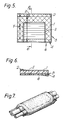
- Figures 1, 3 and 5 are diagrammatic plan views of heaters of the invention and Figures 2, 4 and 6 are diagrammatic cross-sections taken on lines 2, 4 and 6 of Figures 1, 3 and 5 respectively.
- a first electrode 1 at the top of the heater is contacted by a first distributed connection means 2
- a second electrode 3 at the bottom of the heater is contacted by a second distributed connection means 4
- a conductive polymer heating element 5 is sandwiched between the-electrodes.
- the heaters comprise a heating area (shown cross-hatched in Figures 1, 3 and 5) and at least one connection area (shown horizontally hatched in Figures 1, 3 and 5).
- the heaters have been prepared from rectangular laminar heaters of the same cross-section throughout, by cutting a channel 11 into the first electrode (and in Figures 3 and 4, by also cutting a channel 31 into the second electrode 3). Also shown are the current paths from the first connection means 2 (solid lines) and from the second connection means 4 (dashed lines) to various points X, Y and Z in the heating areas. It will be seen that in each case at least one of the current paths is a straight line. Also shown in Figure 6 is a heat-responsive member 6, e.g. a heat-shrinkable sheet and/or a heat-activated adhesive.
- a heat-responsive member 6 e.g. a heat-shrinkable sheet and/or a heat-activated adhesive.
- Figure 7 is a diagrammatic perspective view of a heat-shrinkable splice case being applied around a telephone cable splice, the interior of the cover having secured thereto a heater of the invention whose heating area is indicated by the dotted lines.
- the invention is further illustrated in the following Example.
- a "slit heater" of the kind described in Patent No. 4,177,446 was made by slitting a rectangular laminate consisting of a sheet 40 mils thick of a PTC conductive polymer sandwiched between two aluminum foils each 0.65 mil thick, and expanding it 4.5 times to give a heater 38.5 inch long and 18.5 inch wide, with 36 diamond-shaped apertures across its width.
- a copper bus bar was attached to one electrode along one side of the sheet and a second copper bus bar was attached to the other electrode along the other side of the sheet. Each bus bar was 0.3125 inch wide and 16 mil thick.
- a channel was cut into the upper surface of the heater in the shape shown in Figure 1, the "window" connection area thus created being about 13.5 inches high and about 18.5 inches wide, the top line of the window being about 4 inches from the top of the heater, and the bottom line of the window being about 1 inch from the bottom of the heater.
- the heater was secured with polyurethane adhesive to the interior of a heat-shrinkable polymeric sleeve, and a 30 mil thick layer of heat-activated adhesive was then applied over the heater.
- the resulting product was wrapped around a substrate, the edges secured together, and the heater powered.
- the resultant heating caused the heat-shrinkable sleeve to shrink into contact with the substrate and to seal along the bond line, while the window area remained unheated and did not shrink.
Abstract
Description
- This invention relates to laminar electrical heaters.
- Laminar electrical heaters, including those which comprise a laminar resistive heating element composed of a conductive polymer, are known. Some of these heaters comprise a pair of laminar electrodes, e.g. of metal foil, an apertured (e.g. pierced, slit or punched) metal foil or sheet, with the heating element sandwiched between them. The heating element preferably exhibits PTC behavior, thus rendering the heater self-regulating. It is also known to make such heaters which are heat-recoverable or which are deformable so that they can be attached to heat-recoverable articles and will not prevent heat-recovery thereof. Reference may be made for example to U.S. Patents Nos. 4,085,286, 4,177,376, 4,177,446, 4,223,209, and 4,318,220, and published European Application No. 63,440. For further details concerning conductive polymers and electrical devices concerning them, reference may be made to U.S. Patents Nos. 2,952,761, 2,978,665, 3,243,753, 3,351,882, 3,571,777, 3,757,086, 3,793,716, 3,823,217, 3,858,144, 3,861,029, 4,017,715, 4,072,848, 4,117,312, 4,177,446, 4,188,276, 4,237,441, 4,242,573, 4,246,468, 4,250,400, 4,255,698, 4,271,350, 4,272,471, 4,304,987, 4,309,596, 4,309,597, 4,314,230, 4,315,237, 4,317,027, 4,318,881 and 4,330,704; J. Applied Polymer Science 19, 813-815 (1975), Klason and Kubat; Polymer Engineering and Science 18, 649-653 (1978), Narkis et al; German OLS 2,634,999; 2,755,077; 2,746,602; 2,755,076; 2,821,799; European Application Nos. 38713, 38714, 38715, 38716 and 38718.
- For a number of uses of laminar heaters, it is desirable to make use of a heater having an irregular shape.
- For example, when such a heater is used as part of a heat-recoverable article, e.g. to cover a splice between telephone cables, recovery of only certain parts of the article may be desired or necessary. Alternatively, if recovery of parts of the article is all that is needed, then even if recovery of the whole article is not harmful, limitations on the available power supply (e.g. a battery or limited AC power) may make it necessary or desirable to restrict heating to those parts of the article which need to recover (and/or provide other thermal response such as heat-activation of an adhesive).
- We have discovered that when it is desired to make use of a laminar heater which comprises a heating element sandwiched between two laminar electrodes and which has an irregular shape, especially one having a cut-out portion (or "window") or a deeply re-entrant portion, serious problems can arise, for example a failure to generate sufficient heat in some areas and/or generation of excessive heat in some areas.
- These problems appear to arise from the fact that the laminar electrodes have significant resistance along the thickness thereof, leading to a loss of potential difference between the electrodes at points which can only be reached by a circuitous path from one or both of the bus connectors, and/or to excessive current densities at restricted portions of the electrodes.
- We have discovered that these problems can be mitigated or overcome by making use-of a heater in which at least one of the electrodes extends over a connection area in which heat is not generated but which provides a shorter and/or more uniform current path to the heatgenerating parts of the heater.
- In one aspect, the invention provides a laminar heater which comprises
- (a) first and second electrodes which can be connected to a source of electrical power; and
- (b) a laminar resistive heating element through which current flows when the electrodes are connected to source of electrical power;
- (1) at least one heating area in which current flows through the heating element between the electrodes, and
- (2) at least one connection area in which current passes through at least one of the electrodes but not through the heating element.
- Although the heaters of the invention can have substantially zero resistance, ie. have an equipotential surface, the invention is of particular value for heaters in which (i) each of the electrodes is a laminar electrode which has low electrical resistance through the thickness thereof but substantial electrical resistance along the thickness thereof, and (ii) the heating element is sandwiched between the electrodes. It is to be understood that the resistance of the electrodes is not usually high in an absolute sense, merely high enough to give rise to the problems noted above. Generally such heaters comprise first and second electrical connection means which (a) can be connected to.a source of electrical power and (b) make distributed electrical contact with the first and second electrodes respectively; there being points on at least one of the electrodes in the heating area which are connected to the respective connection means by a path of least electrical resistance which passes through the connection area.
- In another aspect, the invention provides a preferred method of making a laminar electrical heater as defined above which generates heat only in preselected areas, which method comprises
- (1) providing a laminar heater comprising
- (a) first and second laminar electrodes,
- (b) a laminar resistive heating element sandwiched between the electrodes; and
- (2) cutting through the first electrode, but not the second electrode, along a line which electrically isolates an area of the first electrode.
- This method results in a heater in which the connection area comprises, in addition to the second electrode, a first laminar member which is substantially the same as the laminar resistive heating element except that current does not pass through it when the connection means are connected to a source of electrical power; and a second laminar member which is substantially the same as the first electrode and is separated from the first electrode by a discontinuity through which current cannot pass. -
- Another method of making a heater as defined above is to prepare a laminate of the heating element and the second electrode, and to apply a suitably shaped first electrode to the opposite face of the heating element. Another method is to apply suitably shaped electrodes to opposite faces of a laminar heating element.
- In another aspect, the invention provides a method of covering a substrate which comprises
- (A) placing adjacent the substrate a heat-recoverable article comprising an electrical heater as defined above, and
- (B) connecting the first and second electrical connection means to a source of electrical power to cause heating of selected areas of the article, at least some of the selected areas shrinking into contact with the substrate.
- For the most uniform heating, preferably all points in the heating area of each electrode are connected to the respective connection means by a path of least electrical resistance which is a straight line on the surface of the electrode. The term "a straight line on the surface of the electrode" is used to mean that if the heater is flat (i.e. planar), or if it is not flat and is (notionally) flattened out, the current path is a geometrically straight line. However, in many cases, sufficiently uniform heating can be obtained even when parts of the heating area are heated via current paths which, from one of the connection means, are not straight. Thus we have found that, when a generally rectangular connection area (window) is to be produced in a generally rectangular heater, between the first and second connection means and closer to one of the connection means, very much better results are obtained if the electrode which spans the connection area is the one whose connection means is closer to the window. Putting this another way, the distance from the first connection means to the window is preferably greater than the distance from the second connection means to the window.
- The heating element can be of any type but preferably it comprises a conductive polymer. It may be of uniform composition, e.g. a single PTC layer, or comprise two or more layers of different conductive polymers, e.g. at least one layer of a ZTC conductive polymer and a layer of a PTC conductive polymer.
- The heater can be used merely to maintain selected areas of a substrate or the surrounding atmosphere at an elevated temperature. However, the heater can itself undergo a thermal response when it is connected to a suitable power source or it can be secured to an element, usually a non-conductive element, which undergoes a thermal response when the heater is connected to a suitable power source. The term "undergo a thermal response" is used herein to denote a change in physical and/or chemical state, in addition to a change in temperature, for example a physical change such as a change in shape, or a chemical reaction. Thus the heater may comprise a conductive polymer element which is heat-recoverable. Alternatively the heater can be secured to an article, e.g. of an organic polymer or a metal, which is heat-recoverable, e.g. heat-shrinkable, or to an element which melts and flows when it is heated, e.g. a heat-activated adhesive or a mastic, or to an element which comprises two components which react together when heated, e.g. a two-part latent adhesive. We have found heaters of the invention to be particularly useful for securing to heat-shrinkable wrap-around articles for covering elongate substrates such as cable splices, the heating areas of the heater being arranged to heat only the areas of the article which require to be heated, in particular the end sections of the article, which shrink into contact with the substrate and which are normally coated with a heat-activated adhesive, and at least one of the longitudinal edge sections of the article, which are held together by a closure device and which are likewise normally coated with a heat-activated adhesive so as to seal the closure area.
- If the heater is itself heat-shrinkable or is secured to an article which is heat-shrinkable, care may be needed to ensure that the desired electroding pattern remains in effect.
- Referring now to the drawings, Figures 1, 3 and 5 are diagrammatic plan views of heaters of the invention and Figures 2, 4 and 6 are diagrammatic cross-sections taken on
lines second electrode 3 at the bottom of the heater is contacted by a second distributed connection means 4, and a conductivepolymer heating element 5 is sandwiched between the-electrodes. The heaters comprise a heating area (shown cross-hatched in Figures 1, 3 and 5) and at least one connection area (shown horizontally hatched in Figures 1, 3 and 5). The heaters have been prepared from rectangular laminar heaters of the same cross-section throughout, by cutting achannel 11 into the first electrode (and in Figures 3 and 4, by also cutting achannel 31 into the second electrode 3). Also shown are the current paths from the first connection means 2 (solid lines) and from the second connection means 4 (dashed lines) to various points X, Y and Z in the heating areas. It will be seen that in each case at least one of the current paths is a straight line. Also shown in Figure 6 is a heat-responsive member 6, e.g. a heat-shrinkable sheet and/or a heat-activated adhesive. - Figure 7 is a diagrammatic perspective view of a heat-shrinkable splice case being applied around a telephone cable splice, the interior of the cover having secured thereto a heater of the invention whose heating area is indicated by the dotted lines.
- The invention is further illustrated in the following Example.
- A "slit heater" of the kind described in Patent No. 4,177,446 was made by slitting a rectangular laminate consisting of a sheet 40 mils thick of a PTC conductive polymer sandwiched between two aluminum foils each 0.65 mil thick, and expanding it 4.5 times to give a heater 38.5 inch long and 18.5 inch wide, with 36 diamond-shaped apertures across its width. A copper bus bar was attached to one electrode along one side of the sheet and a second copper bus bar was attached to the other electrode along the other side of the sheet. Each bus bar was 0.3125 inch wide and 16 mil thick. Using a router equipped with a carbide tip, a channel was cut into the upper surface of the heater in the shape shown in Figure 1, the "window" connection area thus created being about 13.5 inches high and about 18.5 inches wide, the top line of the window being about 4 inches from the top of the heater, and the bottom line of the window being about 1 inch from the bottom of the heater.
- The heater was secured with polyurethane adhesive to the interior of a heat-shrinkable polymeric sleeve, and a 30 mil thick layer of heat-activated adhesive was then applied over the heater.
- The resulting product was wrapped around a substrate, the edges secured together, and the heater powered. The resultant heating caused the heat-shrinkable sleeve to shrink into contact with the substrate and to seal along the bond line, while the window area remained unheated and did not shrink.
the heater comprising, when the electrodes are connected to a source of electrical power, "
Claims (10)
the heater comprising, when the electrodes are connected to a source of electrical power,
Priority Applications (1)
| Application Number | Priority Date | Filing Date | Title |
|---|---|---|---|
| AT84303152T ATE36796T1 (en) | 1983-05-11 | 1984-05-10 | LAMINATED ELECTRIC HEATERS. |
Applications Claiming Priority (2)
| Application Number | Priority Date | Filing Date | Title |
|---|---|---|---|
| US493445 | 1983-05-11 | ||
| US06/493,445 US4517449A (en) | 1983-05-11 | 1983-05-11 | Laminar electrical heaters |
Publications (2)
| Publication Number | Publication Date |
|---|---|
| EP0128664A1 true EP0128664A1 (en) | 1984-12-19 |
| EP0128664B1 EP0128664B1 (en) | 1988-08-24 |
Family
ID=23960255
Family Applications (1)
| Application Number | Title | Priority Date | Filing Date |
|---|---|---|---|
| EP84303152A Expired EP0128664B1 (en) | 1983-05-11 | 1984-05-10 | Laminar electrical heaters |
Country Status (11)
| Country | Link |
|---|---|
| US (1) | US4517449A (en) |
| EP (1) | EP0128664B1 (en) |
| JP (1) | JPS59214187A (en) |
| KR (1) | KR850000165A (en) |
| AT (1) | ATE36796T1 (en) |
| AU (1) | AU580552B2 (en) |
| BR (1) | BR8402218A (en) |
| CA (1) | CA1226027A (en) |
| DE (1) | DE3473721D1 (en) |
| ES (1) | ES8600599A1 (en) |
| GB (1) | GB2141610A (en) |
Cited By (6)
| Publication number | Priority date | Publication date | Assignee | Title |
|---|---|---|---|---|
| EP0280498A2 (en) * | 1987-02-24 | 1988-08-31 | N.V. Raychem S.A. | Electrical device |
| EP0307200A2 (en) * | 1987-09-09 | 1989-03-15 | Raychem A/S | Heat recoverable article |
| EP0307198A2 (en) * | 1987-09-09 | 1989-03-15 | Raychem Limited | Conductive polymeric article |
| WO1990003057A1 (en) * | 1988-09-08 | 1990-03-22 | Raychem Corporation | Method of cable sealing |
| EP0388990A2 (en) | 1986-02-20 | 1990-09-26 | RAYCHEM CORPORATION (a Delaware corporation) | Method and articles employing ion exchange material |
| WO2021043693A1 (en) * | 2019-09-06 | 2021-03-11 | Jt International Sa | Heater assembly |
Families Citing this family (13)
| Publication number | Priority date | Publication date | Assignee | Title |
|---|---|---|---|---|
| JPS6091583A (en) * | 1983-10-24 | 1985-05-22 | 松下電器産業株式会社 | Heat generator |
| US4616125A (en) * | 1984-02-03 | 1986-10-07 | Eltac Nogler & Daum Kg | Heating element |
| DE3583932D1 (en) * | 1984-12-18 | 1991-10-02 | Matsushita Electric Ind Co Ltd | SELF-REGULATING HEATING ITEM WITH ELECTRODES THAT ARE DIRECTLY CONNECTED TO A PTC LAYER. |
| US4801785A (en) * | 1986-01-14 | 1989-01-31 | Raychem Corporation | Electrical devices |
| GB8604501D0 (en) * | 1986-02-24 | 1986-04-03 | Raychem Sa Nv | Cable splice case |
| GB2225493B (en) * | 1988-11-19 | 1992-10-21 | Bowthorpe Hellermann Ltd | Sealing cable splice closures |
| US5408574A (en) * | 1989-12-01 | 1995-04-18 | Philip Morris Incorporated | Flat ceramic heater having discrete heating zones |
| GB2252285B (en) * | 1991-01-29 | 1994-07-06 | British Aerospace | Method and apparatus for separating a frozen deposit from a substrate |
| US5468936A (en) * | 1993-03-23 | 1995-11-21 | Philip Morris Incorporated | Heater having a multiple-layer ceramic substrate and method of fabrication |
| JP2003520420A (en) * | 2000-01-11 | 2003-07-02 | タイコ・エレクトロニクス・コーポレイション | Electrical device |
| US7442904B2 (en) * | 2005-02-25 | 2008-10-28 | Tutco, Inc. | Metal sheathed heater and thermostat assembly and method of use |
| US20190098703A1 (en) * | 2017-09-26 | 2019-03-28 | E I Du Pont De Nemours And Company | Heating elements and heating devices |
| FR3087991B1 (en) * | 2018-10-29 | 2022-12-09 | Commissariat Energie Atomique | PREPARATION OF A HEATING SYSTEM FROM A HEAT-SHRINK SUBSTRATE |
Citations (6)
| Publication number | Priority date | Publication date | Assignee | Title |
|---|---|---|---|---|
| US2952761A (en) * | 1957-04-02 | 1960-09-13 | Chemelex Inc | Electrically conductive laminated structure and method of making same |
| US2978665A (en) * | 1956-07-11 | 1961-04-04 | Antioch College | Regulator device for electric current |
| US3221145A (en) * | 1963-09-06 | 1965-11-30 | Armstrong Cork Co | Laminated heating sheet |
| US4085286A (en) * | 1974-09-27 | 1978-04-18 | Raychem Corporation | Heat-recoverable sealing article with self-contained heating means and method of sealing a splice therewith |
| US4177446A (en) * | 1975-12-08 | 1979-12-04 | Raychem Corporation | Heating elements comprising conductive polymers capable of dimensional change |
| DE2901711A1 (en) * | 1979-01-17 | 1980-07-31 | Siemens Ag | Electrode coating for ceramic PTC resistor for AC mains - consists of e.g. treated silver applied by plasma injection etc. and soldered leads |
Family Cites Families (10)
| Publication number | Priority date | Publication date | Assignee | Title |
|---|---|---|---|---|
| NL123804C (en) * | 1963-04-30 | |||
| GB1112274A (en) * | 1965-06-17 | 1968-05-01 | Armstrong Cork Co | Improvements in or relating to electric heaters |
| US3397302A (en) * | 1965-12-06 | 1968-08-13 | Harry W. Hosford | Flexible sheet-like electric heater |
| US3535494A (en) * | 1966-11-22 | 1970-10-20 | Fritz Armbruster | Electric heating mat |
| US3448246A (en) * | 1967-10-09 | 1969-06-03 | Fritz Armbruster | Electrical heating mat with automatic temperature control |
| GB1409652A (en) * | 1971-07-09 | 1975-10-08 | Enggaard J K | Electric heating elements |
| US3878362A (en) * | 1974-02-15 | 1975-04-15 | Du Pont | Electric heater having laminated structure |
| US4330703A (en) * | 1975-08-04 | 1982-05-18 | Raychem Corporation | Layered self-regulating heating article |
| US4272471A (en) * | 1979-05-21 | 1981-06-09 | Raychem Corporation | Method for forming laminates comprising an electrode and a conductive polymer layer |
| US4317027A (en) * | 1980-04-21 | 1982-02-23 | Raychem Corporation | Circuit protection devices |
-
1983
- 1983-05-11 US US06/493,445 patent/US4517449A/en not_active Expired - Fee Related
-
1984
- 1984-05-10 EP EP84303152A patent/EP0128664B1/en not_active Expired
- 1984-05-10 AU AU27896/84A patent/AU580552B2/en not_active Ceased
- 1984-05-10 CA CA000454040A patent/CA1226027A/en not_active Expired
- 1984-05-10 GB GB08411927A patent/GB2141610A/en not_active Withdrawn
- 1984-05-10 DE DE8484303152T patent/DE3473721D1/en not_active Expired
- 1984-05-10 KR KR1019840002510A patent/KR850000165A/en not_active Application Discontinuation
- 1984-05-10 ES ES532367A patent/ES8600599A1/en not_active Expired
- 1984-05-10 BR BR8402218A patent/BR8402218A/en not_active IP Right Cessation
- 1984-05-10 AT AT84303152T patent/ATE36796T1/en active
- 1984-05-11 JP JP59095473A patent/JPS59214187A/en active Pending
Patent Citations (6)
| Publication number | Priority date | Publication date | Assignee | Title |
|---|---|---|---|---|
| US2978665A (en) * | 1956-07-11 | 1961-04-04 | Antioch College | Regulator device for electric current |
| US2952761A (en) * | 1957-04-02 | 1960-09-13 | Chemelex Inc | Electrically conductive laminated structure and method of making same |
| US3221145A (en) * | 1963-09-06 | 1965-11-30 | Armstrong Cork Co | Laminated heating sheet |
| US4085286A (en) * | 1974-09-27 | 1978-04-18 | Raychem Corporation | Heat-recoverable sealing article with self-contained heating means and method of sealing a splice therewith |
| US4177446A (en) * | 1975-12-08 | 1979-12-04 | Raychem Corporation | Heating elements comprising conductive polymers capable of dimensional change |
| DE2901711A1 (en) * | 1979-01-17 | 1980-07-31 | Siemens Ag | Electrode coating for ceramic PTC resistor for AC mains - consists of e.g. treated silver applied by plasma injection etc. and soldered leads |
Cited By (10)
| Publication number | Priority date | Publication date | Assignee | Title |
|---|---|---|---|---|
| EP0388990A2 (en) | 1986-02-20 | 1990-09-26 | RAYCHEM CORPORATION (a Delaware corporation) | Method and articles employing ion exchange material |
| EP0280498A2 (en) * | 1987-02-24 | 1988-08-31 | N.V. Raychem S.A. | Electrical device |
| EP0280498A3 (en) * | 1987-02-24 | 1990-02-07 | N.V. Raychem S.A. | Electrical device |
| EP0307200A2 (en) * | 1987-09-09 | 1989-03-15 | Raychem A/S | Heat recoverable article |
| EP0307198A2 (en) * | 1987-09-09 | 1989-03-15 | Raychem Limited | Conductive polymeric article |
| EP0307200A3 (en) * | 1987-09-09 | 1991-03-20 | Raychem A/S | Heat recoverable article |
| EP0307198A3 (en) * | 1987-09-09 | 1991-03-20 | Raychem Limited | Conductive polymeric article |
| WO1990003057A1 (en) * | 1988-09-08 | 1990-03-22 | Raychem Corporation | Method of cable sealing |
| US4950343A (en) * | 1988-09-08 | 1990-08-21 | Raychem Corporation | Method of cable sealing |
| WO2021043693A1 (en) * | 2019-09-06 | 2021-03-11 | Jt International Sa | Heater assembly |
Also Published As
| Publication number | Publication date |
|---|---|
| ES532367A0 (en) | 1985-09-16 |
| JPS59214187A (en) | 1984-12-04 |
| DE3473721D1 (en) | 1988-09-29 |
| EP0128664B1 (en) | 1988-08-24 |
| US4517449A (en) | 1985-05-14 |
| CA1226027A (en) | 1987-08-25 |
| ATE36796T1 (en) | 1988-09-15 |
| GB8411927D0 (en) | 1984-06-13 |
| ES8600599A1 (en) | 1985-09-16 |
| BR8402218A (en) | 1984-12-26 |
| AU2789684A (en) | 1984-11-15 |
| KR850000165A (en) | 1985-02-25 |
| GB2141610A (en) | 1984-12-19 |
| AU580552B2 (en) | 1989-01-19 |
Similar Documents
| Publication | Publication Date | Title |
|---|---|---|
| EP0128664B1 (en) | Laminar electrical heaters | |
| EP0117762B1 (en) | Electrically heat-recoverable article | |
| US4845343A (en) | Electrical devices comprising fabrics | |
| US4777351A (en) | Devices comprising conductive polymer compositions | |
| US4761541A (en) | Devices comprising conductive polymer compositions | |
| EP0340361B1 (en) | Electrical device comprising a PTC-resistive polymer element | |
| US4719335A (en) | Devices comprising conductive polymer compositions | |
| US4532164A (en) | Heat-shrinkable article | |
| CA1266331A (en) | Self-regulating ptc heater | |
| CA1262467A (en) | Devices comprising ptc conductive polymers | |
| EP3320754B1 (en) | Trimmable heater | |
| KR950010011A (en) | Resistor structure and resistance value setting method | |
| EP0127457B1 (en) | Electrically heat-recoverable article | |
| CA2045529A1 (en) | Flexible heating element | |
| EP0158410A1 (en) | Laminar Conductive polymer devices | |
| US4548662A (en) | Method of providing a protective covering over a substrate | |
| US4593181A (en) | Heating element having deformed buss bars | |
| EP0307198B1 (en) | Conductive polymeric article | |
| EP0307007B1 (en) | Making electrical contact between metals and resistive elements | |
| EP0209224B1 (en) | Sheet heaters | |
| EP0397685B1 (en) | Laminar electrical heaters | |
| JPS60184836A (en) | Laminated conductive polymer device |
Legal Events
| Date | Code | Title | Description |
|---|---|---|---|
| PUAI | Public reference made under article 153(3) epc to a published international application that has entered the european phase |
Free format text: ORIGINAL CODE: 0009012 |
|
| 17P | Request for examination filed |
Effective date: 19840530 |
|
| AK | Designated contracting states |
Designated state(s): AT BE CH DE FR GB IT LI NL SE |
|
| 17Q | First examination report despatched |
Effective date: 19861003 |
|
| D17Q | First examination report despatched (deleted) | ||
| RAP1 | Party data changed (applicant data changed or rights of an application transferred) |
Owner name: RAYCHEM CORPORATION (A DELAWARE CORPORATION) |
|
| GRAA | (expected) grant |
Free format text: ORIGINAL CODE: 0009210 |
|
| AK | Designated contracting states |
Kind code of ref document: B1 Designated state(s): AT BE CH DE FR GB IT LI NL SE |
|
| PG25 | Lapsed in a contracting state [announced via postgrant information from national office to epo] |
Ref country code: AT Effective date: 19880824 |
|
| REF | Corresponds to: |
Ref document number: 36796 Country of ref document: AT Date of ref document: 19880915 Kind code of ref document: T |
|
| REF | Corresponds to: |
Ref document number: 3473721 Country of ref document: DE Date of ref document: 19880929 |
|
| ITF | It: translation for a ep patent filed |
Owner name: MODIANO & ASSOCIATI S.R.L. |
|
| ET | Fr: translation filed | ||
| PLBE | No opposition filed within time limit |
Free format text: ORIGINAL CODE: 0009261 |
|
| STAA | Information on the status of an ep patent application or granted ep patent |
Free format text: STATUS: NO OPPOSITION FILED WITHIN TIME LIMIT |
|
| 26N | No opposition filed | ||
| ITTA | It: last paid annual fee | ||
| EAL | Se: european patent in force in sweden |
Ref document number: 84303152.7 |
|
| PGFP | Annual fee paid to national office [announced via postgrant information from national office to epo] |
Ref country code: GB Payment date: 19950501 Year of fee payment: 12 |
|
| PGFP | Annual fee paid to national office [announced via postgrant information from national office to epo] |
Ref country code: FR Payment date: 19950510 Year of fee payment: 12 |
|
| PGFP | Annual fee paid to national office [announced via postgrant information from national office to epo] |
Ref country code: DE Payment date: 19950511 Year of fee payment: 12 |
|
| PGFP | Annual fee paid to national office [announced via postgrant information from national office to epo] |
Ref country code: CH Payment date: 19950516 Year of fee payment: 12 |
|
| PGFP | Annual fee paid to national office [announced via postgrant information from national office to epo] |
Ref country code: SE Payment date: 19950517 Year of fee payment: 12 |
|
| PGFP | Annual fee paid to national office [announced via postgrant information from national office to epo] |
Ref country code: NL Payment date: 19950531 Year of fee payment: 12 |
|
| PGFP | Annual fee paid to national office [announced via postgrant information from national office to epo] |
Ref country code: BE Payment date: 19950712 Year of fee payment: 12 |
|
| PG25 | Lapsed in a contracting state [announced via postgrant information from national office to epo] |
Ref country code: GB Effective date: 19960510 |
|
| PG25 | Lapsed in a contracting state [announced via postgrant information from national office to epo] |
Ref country code: SE Effective date: 19960511 |
|
| PG25 | Lapsed in a contracting state [announced via postgrant information from national office to epo] |
Ref country code: LI Effective date: 19960531 Ref country code: CH Effective date: 19960531 Ref country code: BE Effective date: 19960531 |
|
| BERE | Be: lapsed |
Owner name: RAYCHEM CORP. Effective date: 19960531 |
|
| PG25 | Lapsed in a contracting state [announced via postgrant information from national office to epo] |
Ref country code: NL Effective date: 19961201 |
|
| GBPC | Gb: european patent ceased through non-payment of renewal fee |
Effective date: 19960510 |
|
| REG | Reference to a national code |
Ref country code: CH Ref legal event code: PL |
|
| PG25 | Lapsed in a contracting state [announced via postgrant information from national office to epo] |
Ref country code: FR Effective date: 19970131 |
|
| PG25 | Lapsed in a contracting state [announced via postgrant information from national office to epo] |
Ref country code: DE Effective date: 19970201 |
|
| EUG | Se: european patent has lapsed |
Ref document number: 84303152.7 |
|
| NLV4 | Nl: lapsed or anulled due to non-payment of the annual fee |
Effective date: 19961201 |
|
| REG | Reference to a national code |
Ref country code: FR Ref legal event code: ST |