EP0128703B1 - Non-contact controlled micropump - Google Patents
Non-contact controlled micropump Download PDFInfo
- Publication number
- EP0128703B1 EP0128703B1 EP84303656A EP84303656A EP0128703B1 EP 0128703 B1 EP0128703 B1 EP 0128703B1 EP 84303656 A EP84303656 A EP 84303656A EP 84303656 A EP84303656 A EP 84303656A EP 0128703 B1 EP0128703 B1 EP 0128703B1
- Authority
- EP
- European Patent Office
- Prior art keywords
- liquid
- valve
- casing
- micropump
- bellows
- Prior art date
- Legal status (The legal status is an assumption and is not a legal conclusion. Google has not performed a legal analysis and makes no representation as to the accuracy of the status listed.)
- Expired
Links
- 239000007788 liquid Substances 0.000 claims description 42
- 230000001105 regulatory effect Effects 0.000 claims description 20
- 239000003380 propellant Substances 0.000 claims description 3
- 230000001276 controlling effect Effects 0.000 claims description 2
- 238000002513 implantation Methods 0.000 claims 1
- NOESYZHRGYRDHS-UHFFFAOYSA-N insulin Chemical compound N1C(=O)C(NC(=O)C(CCC(N)=O)NC(=O)C(CCC(O)=O)NC(=O)C(C(C)C)NC(=O)C(NC(=O)CN)C(C)CC)CSSCC(C(NC(CO)C(=O)NC(CC(C)C)C(=O)NC(CC=2C=CC(O)=CC=2)C(=O)NC(CCC(N)=O)C(=O)NC(CC(C)C)C(=O)NC(CCC(O)=O)C(=O)NC(CC(N)=O)C(=O)NC(CC=2C=CC(O)=CC=2)C(=O)NC(CSSCC(NC(=O)C(C(C)C)NC(=O)C(CC(C)C)NC(=O)C(CC=2C=CC(O)=CC=2)NC(=O)C(CC(C)C)NC(=O)C(C)NC(=O)C(CCC(O)=O)NC(=O)C(C(C)C)NC(=O)C(CC(C)C)NC(=O)C(CC=2NC=NC=2)NC(=O)C(CO)NC(=O)CNC2=O)C(=O)NCC(=O)NC(CCC(O)=O)C(=O)NC(CCCNC(N)=N)C(=O)NCC(=O)NC(CC=3C=CC=CC=3)C(=O)NC(CC=3C=CC=CC=3)C(=O)NC(CC=3C=CC(O)=CC=3)C(=O)NC(C(C)O)C(=O)N3C(CCC3)C(=O)NC(CCCCN)C(=O)NC(C)C(O)=O)C(=O)NC(CC(N)=O)C(O)=O)=O)NC(=O)C(C(C)CC)NC(=O)C(CO)NC(=O)C(C(C)O)NC(=O)C1CSSCC2NC(=O)C(CC(C)C)NC(=O)C(NC(=O)C(CCC(N)=O)NC(=O)C(CC(N)=O)NC(=O)C(NC(=O)C(N)CC=1C=CC=CC=1)C(C)C)CC1=CN=CN1 NOESYZHRGYRDHS-UHFFFAOYSA-N 0.000 description 6
- 102000004877 Insulin Human genes 0.000 description 3
- 108090001061 Insulin Proteins 0.000 description 3
- 229940125396 insulin Drugs 0.000 description 3
- 239000008280 blood Substances 0.000 description 2
- 210000004369 blood Anatomy 0.000 description 2
- 239000003814 drug Substances 0.000 description 2
- 208000015181 infectious disease Diseases 0.000 description 2
- 238000001802 infusion Methods 0.000 description 2
- 238000002347 injection Methods 0.000 description 2
- 239000007924 injection Substances 0.000 description 2
- 229910000859 α-Fe Inorganic materials 0.000 description 2
- WQZGKKKJIJFFOK-GASJEMHNSA-N Glucose Natural products OC[C@H]1OC(O)[C@H](O)[C@@H](O)[C@@H]1O WQZGKKKJIJFFOK-GASJEMHNSA-N 0.000 description 1
- 230000036760 body temperature Effects 0.000 description 1
- 230000003247 decreasing effect Effects 0.000 description 1
- 230000004069 differentiation Effects 0.000 description 1
- 230000000694 effects Effects 0.000 description 1
- 239000008103 glucose Substances 0.000 description 1
- 238000013101 initial test Methods 0.000 description 1
- 238000012856 packing Methods 0.000 description 1
- 239000000126 substance Substances 0.000 description 1
- 210000001835 viscera Anatomy 0.000 description 1
Images


Classifications
-
- A—HUMAN NECESSITIES
- A61—MEDICAL OR VETERINARY SCIENCE; HYGIENE
- A61M—DEVICES FOR INTRODUCING MEDIA INTO, OR ONTO, THE BODY; DEVICES FOR TRANSDUCING BODY MEDIA OR FOR TAKING MEDIA FROM THE BODY; DEVICES FOR PRODUCING OR ENDING SLEEP OR STUPOR
- A61M5/00—Devices for bringing media into the body in a subcutaneous, intra-vascular or intramuscular way; Accessories therefor, e.g. filling or cleaning devices, arm-rests
- A61M5/14—Infusion devices, e.g. infusing by gravity; Blood infusion; Accessories therefor
- A61M5/142—Pressure infusion, e.g. using pumps
- A61M5/14244—Pressure infusion, e.g. using pumps adapted to be carried by the patient, e.g. portable on the body
- A61M5/14276—Pressure infusion, e.g. using pumps adapted to be carried by the patient, e.g. portable on the body specially adapted for implantation
-
- A—HUMAN NECESSITIES
- A61—MEDICAL OR VETERINARY SCIENCE; HYGIENE
- A61M—DEVICES FOR INTRODUCING MEDIA INTO, OR ONTO, THE BODY; DEVICES FOR TRANSDUCING BODY MEDIA OR FOR TAKING MEDIA FROM THE BODY; DEVICES FOR PRODUCING OR ENDING SLEEP OR STUPOR
- A61M2205/00—General characteristics of the apparatus
- A61M2205/35—Communication
- A61M2205/3507—Communication with implanted devices, e.g. external control
- A61M2205/3515—Communication with implanted devices, e.g. external control using magnetic means
-
- Y—GENERAL TAGGING OF NEW TECHNOLOGICAL DEVELOPMENTS; GENERAL TAGGING OF CROSS-SECTIONAL TECHNOLOGIES SPANNING OVER SEVERAL SECTIONS OF THE IPC; TECHNICAL SUBJECTS COVERED BY FORMER USPC CROSS-REFERENCE ART COLLECTIONS [XRACs] AND DIGESTS
- Y10—TECHNICAL SUBJECTS COVERED BY FORMER USPC
- Y10S—TECHNICAL SUBJECTS COVERED BY FORMER USPC CROSS-REFERENCE ART COLLECTIONS [XRACs] AND DIGESTS
- Y10S128/00—Surgery
- Y10S128/12—Pressure infusion
Landscapes
- Health & Medical Sciences (AREA)
- Vascular Medicine (AREA)
- Engineering & Computer Science (AREA)
- Anesthesiology (AREA)
- Biomedical Technology (AREA)
- Heart & Thoracic Surgery (AREA)
- Hematology (AREA)
- Life Sciences & Earth Sciences (AREA)
- Animal Behavior & Ethology (AREA)
- General Health & Medical Sciences (AREA)
- Public Health (AREA)
- Veterinary Medicine (AREA)
- Infusion, Injection, And Reservoir Apparatuses (AREA)
Description
- This invention relates to a micropump, particularly one which can be implanted in a body and controlled from outside the body.
- More particularly, the invention relates to a micropump to be disposed within a human body for continuously delivering small quantities of a pharmaceutical liquid into the human body. With the invention the delivery rate can be controlled by the action of pharmaceutical liquid injection control device in response to external electric signals.
- Generally, pharmaceutical liquids are injected by one day's dose at a time. This is often excessive and a major amount is rapidly drained off. As a result, the remaining liquid is insufficient over the subsequent period.
- The aim of this invention is to provide a micropump for continually directly delivering a pharmaceutical liquid in small quantities to a human body.
- Transactions of the American Society of Artificial Internal Organs, Volume 24, 1978, pages 229 to 231 "Design and initial testing of a totally implantable transcutaneously controllable insulin delivering device" discloses a micropump in accordance with the prior art portion of
claim 1. This prior art device is arranged to supply liquid continuously and the magnet controllable valve is used to direct the flow selectively through flow paths of differing resistance. This does not give the same reliable dosing as can be achieved having an accurately controllable on/off valve and also requires a relatively bulky restrictive flow path which can be liable to blockage. The present invention is characterised as set out inClaim 1. In addition to the advantageous provision of the on/ off control under the control of an external electro-magnet the present invention also provides for the propellant to be received within the bellows and the liquid to be received between the bellows and the casing. - The micropump of the invention can operate in response to external electric signals, the micropump storing the doses of some days. These doses can be injected at once into a reservoir situated in the human body.
- The invention is useful in various fields, particularly, for medical use in which the concentration of pharmaceuticals or essential substances in a living body should be constantly maintained.
- For example, commonly used pharmaceuticals can remain at a constant concentration in blood if they are introduced at a constant rate. Also, in order to ensure a constant concentration of glucose in the blood, insulin delivery doses must always be changed in accordance with the patient's moment-to-moment needs, which vary in accordance with the conditions of the living body.
- Conventional insulin-infusion pumps, which are externally placed and designed percutaneously to inject insulin, have many problems including the risk of infection via the pierced site on the skin, and considerably restrict the patient's ordinary activities.
- With the invention, the pump body can be implanted in the living body, while the control part is externally placed. This eliminates the need repeatedly to pierce the skin for injecting a pharmaceutical liquid and reduces the risk of infection. The external control part including a power supply can be small enough and light as compared with conventional pump bodies.
- Preferably, the micropump includes a pressure regulating valve for regulating the pressure of the liquid pressured by the bellows prior to supply of such liquid to the first said valve.
- A preferred embodiment of this invention will now be described by way of example with ref-. erence to the accompanying drawings, in which:-
- Figure 1 is a sectional view along line I-I of Figure 2 showing a pump of this invention;
- Figure 2 is a plan view of the pump of Figure 1;
- Figure 3 is a sectional view along line III-III of Figure 1;
- Figure 4 is a sectional view along line IV-IV of Figure 5 showing a pressure regulating valve used in the pump;
- Figure 5 is a plan view of the valve of Figure 4;
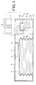
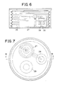
- Figure 6 is a sectional view along VI-VI of Figure 7 showing an example incorporating the pressure regulating valve of Figure 4; and
- Figure 7 is a plan view.
- The apparatus shown in Figures 1 to 3 is designed to be implanted and includes a
bellows 1 enclosing air or gas which in use is expanded by the increase of the air, gas or vaporized gas pressure therein as a result of the body temperature. Acasing 2 houses a pharmaceuticalliquid reservoir 5. A pharmaceutical liquid can be previously injected into thepharmaceutical liquid reservoir 5 via an inlet 3 through thecasing 2 and arubber packing 4 located against the inlet. Injection can be by means of an injector needle. As shown in Figure 2 the inlet 3 does not overlap thebellows 1 in the direction in which an injector needle would be inserted into the inlet 3 for the supply of liquid to thereservoir 5. When thebellows 1 is expanded, the pharmaceutical liquid tends to be expelled fromchamber 5 and presses apermanent magnet valve 6 against avalve seat 7 thus closing anoutlet 11 from the apparatus. Thevalve 6 is usually attracted magnetically towards aferrite core 8 to prevent leakage of the pharmaceutical liquid. In order to open thevalve 6, a force of magnetic attraction stronger than the the force applied bycore 8 is applied by anexternal electromagnet 9 and lifts thevalve 6 from thevalve seat 7, whereon pharmaceutical liquid is released from the pharmaceuticalliquid outlet 11 via abypass path 10 round thevalve 6. When the force of magnetic attraction produced by theelectromagnet 9 is removed thevalve 6 is attracted to theferrite core 8 to close the valve seat and to stop the release of the pharmaceutical liquid. The dose released is controlled by the duration theelectromagnet 9 is applied. - In this way, the pharmaceutical liquid infusion can be externally controlled as required and at any time, while there need be no difficulties due to, for instance, an exhausted battery because the power source for controlling the delivered quantities is located outside the body.
- Figures 4 to 7 illustrate a pressure regulating valve for use in a delivery system as described above.
- In order to inject only a very small quantity of pharmaceutical liquid it is necessary to have a small diameter of valve and to limit the pressure of the pharmaceutical liquid to be injected. For this purpose, it is possible to reduce the pressure to tolerable limits by means of a pressure regulating valve interposed between the permanent magnet valve and the pharmaceutical liquid reservoir, which is pressurised by the bellows. Figures 4 and 5 show a pressure regulating valve, of very small type, which can be used for this purpose, and Figures 6 and 7 show an example of application of such a pressure regulating valve to a micropump of the invention.
- In Figure 4, a liquid of primary pressure enters through an
inlet 13 of abody 12, and passes through a gap between thebody 12 and a regulatingvalve 16, which is urged upward by the elastic force of arubber member 14 and apressure receiving plate 15. The liquid reaches a region of contact between the regulatingvalve 16 and avalve seat 18 of asheet 17. The regulatingvalve 16 is pressed by a rod 20 connected to a diaphragm 21 and to aneedle 19 placed at the center of the valve seat. The diaphragm 21 itself receives pressure from a pressure receiving plate 24 subject to the elastic force of a rubber plate 23 pressed by acover 22. - The regulating
valve 16 is urged upward by the elastic force F1 of therubber plate 14 and a force AP,, where F1 is a small force for firmly contacting the regulatingvalve 16 with thevalve 18, P1 is the primary pressure and A isthe area of thevalve seat 18. In practice the diaphragm 21 is at an initial position where the elastic force of the rubber plate 23 is adjusted so that the force thrusting theneedle 19 downward under the pressure exerted on the diaphragm 21 is equal to the upward force of the regulating valve. When the elastic force of the rubber plate 23 is slightly increased, the diaphragm 21 is moved below the initial position and theneedle 19 is urged on the regulatingvalve 16, thus causing the liquid at primary pressure to flow out from anoutlet 25 via a gap around theneedle 19 and the rod 20. When theoutlet 25 is closed, the secondary pressure in the outlet is increased to move the diaphragm 21 up to its initial position. Accordingly, if the elastic force of the rubber plate 23 is adjusted in such a mannerthatthe secondary pressure is equal to a desired pressure P2, an expected constant pressure is obtained when the outlet is closed. When theoutlet 25 is slightly opened, the liquid flows out and the secondary pressure P2 is decreased. Thus, the diaphragm 21 is moved downward to allow the needle to open the regulating valve so that the liquid is delivered on the secondary pressure side. The secondary pressure is now increased and the diaphragm 21 restores the initial position,. thereby closing thevalve seat 18 to stop the liquid inflow. In this stage, the secondary pressure comes to an expected value, since the rubber plate 23 is arranged to ensure P2. Accordingly, the secondary pressure is unchanged whether the inflow is nothing or at any rate. - Further, the secondary pressure is not changed even if the primary pressure is changed. The force applied to the diaphragm 21 is given by (B-A)P2, where B is the area of the diaphragm 21. When the diaphragm 21 is atthe initial position and all the forces are balanced,

- As F" B and A are constants, differentiation of the pressure P gives

- If the valve seat has a tenth of the diameter of the diaphragm, A is a hundredth of B and the variation of P2 is only 1/99 of the variation of Pl. Accordingly, the pressure regulating valve as described above has the advantage that the-secondary pressure variation can be ignored even if the primary pressure is changed.
- Figures 6 and 7 show an example incorporating such a
pressure regulating valve 27, as described above, as well as a pharmaceuticalliquid reservoir 26, avalve 28, a pharmaceuticalliquid inlet 29 and pharmaceuticalliquid outlet 30.
Claims (5)
Applications Claiming Priority (4)
| Application Number | Priority Date | Filing Date | Title |
|---|---|---|---|
| JP58097327A JPS59222160A (en) | 1983-05-31 | 1983-05-31 | Non-contact control minute amount pump |
| JP97327/83 | 1983-05-31 | ||
| JP115375/83 | 1983-07-25 | ||
| JP11537583U JPS6025011U (en) | 1983-07-25 | 1983-07-25 | Low pressure adjustment constant pressure valve |
Publications (2)
| Publication Number | Publication Date |
|---|---|
| EP0128703A1 EP0128703A1 (en) | 1984-12-19 |
| EP0128703B1 true EP0128703B1 (en) | 1988-01-07 |
Family
ID=26438523
Family Applications (1)
| Application Number | Title | Priority Date | Filing Date |
|---|---|---|---|
| EP84303656A Expired EP0128703B1 (en) | 1983-05-31 | 1984-05-31 | Non-contact controlled micropump |
Country Status (4)
| Country | Link |
|---|---|
| US (1) | US4673391A (en) |
| EP (1) | EP0128703B1 (en) |
| CA (1) | CA1237600A (en) |
| DE (1) | DE3468328D1 (en) |
Cited By (1)
| Publication number | Priority date | Publication date | Assignee | Title |
|---|---|---|---|---|
| DE19507978A1 (en) * | 1995-03-07 | 1996-09-12 | Heinzl Joachim | Burner arrangement for liquid fuels |
Families Citing this family (41)
| Publication number | Priority date | Publication date | Assignee | Title |
|---|---|---|---|---|
| US4718893A (en) * | 1986-02-03 | 1988-01-12 | University Of Minnesota | Pressure regulated implantable infusion pump |
| AT384737B (en) * | 1986-04-04 | 1987-12-28 | Thoma Dipl Ing Dr Techn Herwig | DEVICE FOR CONTINUOUSLY DELIVERING LIQUID MEDICINAL PRODUCTS |
| US4846806A (en) * | 1987-10-06 | 1989-07-11 | 501 Regents Of University Of Minnesota | Implantable intravascular access system |
| US4938742A (en) * | 1988-02-04 | 1990-07-03 | Smits Johannes G | Piezoelectric micropump with microvalves |
| US4978338A (en) † | 1988-04-21 | 1990-12-18 | Therex Corp. | Implantable infusion apparatus |
| US5011472A (en) * | 1988-09-06 | 1991-04-30 | Brown University Research Foundation | Implantable delivery system for biological factors |
| US4943279A (en) * | 1988-09-30 | 1990-07-24 | C. R. Bard, Inc. | Medical pump with infusion controlled by a detachable coded label |
| US5197322A (en) * | 1990-11-29 | 1993-03-30 | Minimed Technologies, Ltd. | Pressure reservoir filling process for an implantable medication infusion pump |
| DE4038049C2 (en) * | 1990-11-29 | 1994-12-01 | Anschuetz & Co Gmbh | Implantable infusion pump |
| US5267964A (en) * | 1992-03-23 | 1993-12-07 | Clintec Nutrition Co. | Fluid control device including automatic valve |
| US5342313A (en) * | 1992-11-02 | 1994-08-30 | Infusion Technologies Corporation | Fluid pump for a flexible, variable geometry reservoir |
| US5232439A (en) * | 1992-11-02 | 1993-08-03 | Infusion Technologies Corporation | Method for pumping fluid from a flexible, variable geometry reservoir |
| DE4334247B4 (en) * | 1993-10-08 | 2006-11-02 | Codman Neuro Sciences Sàrl | A method of adjusting a switchable flow restricting device and a device operating according to the method |
| US5443450A (en) * | 1994-04-29 | 1995-08-22 | Medtronic, Inc. | Medication delivery device and method of construction |
| EP0988838B1 (en) * | 1995-03-23 | 2003-05-21 | Advanced Animal Technology Limited | Substance delivery device |
| US6048328A (en) * | 1998-02-02 | 2000-04-11 | Medtronic, Inc. | Implantable drug infusion device having an improved valve |
| US6077299A (en) * | 1998-06-22 | 2000-06-20 | Eyetronic, Llc | Non-invasively adjustable valve implant for the drainage of aqueous humor in glaucoma |
| US6494867B1 (en) | 1999-04-28 | 2002-12-17 | Sten-Olof Elver | Medical device |
| US6464671B1 (en) | 1999-04-28 | 2002-10-15 | Sten-Olof Elver | Medical system |
| DE60006109T2 (en) * | 1999-04-28 | 2004-08-19 | Sten-Olof Elfver | IMPLANTABLE MEDICINE DISPENSING SYSTEM |
| EP1173241B1 (en) * | 1999-04-28 | 2004-05-19 | Sten-Olof Elfver | Implantable drug delivery system |
| US6635049B1 (en) * | 1999-04-30 | 2003-10-21 | Medtronic, Inc. | Drug bolus delivery system |
| WO2000066204A1 (en) * | 1999-04-30 | 2000-11-09 | University Of Southern California | Implantable microbolus infusion pump |
| US6764472B1 (en) * | 2000-01-11 | 2004-07-20 | Bard Access Systems, Inc. | Implantable refillable infusion device |
| DE60132909T2 (en) | 2000-11-03 | 2009-02-12 | Allergan Medical S.A. | IMPLANTABLE MEDICAL DEVICE FOR DISPENSING A LIQUID |
| WO2002055136A2 (en) * | 2000-12-01 | 2002-07-18 | Nephros Therapeutics Inc | Intrasvascular drug delivery device and use therefor |
| WO2002076533A1 (en) * | 2001-03-27 | 2002-10-03 | Alessandro Giannessi | Magnetically operated, subcutaneously implantable drug infusion device |
| KR100407467B1 (en) * | 2001-07-12 | 2003-11-28 | 최수봉 | Insulin pump operated by remote-controller |
| DE102004016443B3 (en) * | 2004-04-03 | 2005-08-18 | Codman Neuro Sciences Sàrl | Valve for infusion pumps comprises a valve body formed by a cylindrical tappet which slides in a cylindrical receiver, and an inflow opening into the receiver in a region of the tappet base |
| WO2006127508A2 (en) * | 2005-05-20 | 2006-11-30 | Wilson Greatbatch Technologies Inc. | Improved configuration for drug delivery systems |
| US8240635B2 (en) * | 2005-10-26 | 2012-08-14 | Codman Neuro Sciences Sárl | Flow rate accuracy of a fluidic delivery system |
| US8141844B2 (en) * | 2005-10-26 | 2012-03-27 | Codman NeuroSciences Sàrl | Flow rate accuracy of a fluidic delivery system |
| CA2637686A1 (en) | 2006-02-02 | 2007-08-16 | Innovative Bio Therapies | An extracorporeal cell-based therapeutic device and delivery system |
| US20090081296A1 (en) * | 2006-02-02 | 2009-03-26 | Humes H David | Extracorporeal cell-based therapeutic device and delivery system |
| US8449500B2 (en) * | 2007-11-16 | 2013-05-28 | Baxter International Inc. | Flow pulsatility dampening devices for closed-loop controlled infusion systems |
| CA2728215A1 (en) * | 2008-06-18 | 2010-06-24 | Innovative Biotherapies, Inc. | Methods for enhanced propagation of cells |
| US10265454B2 (en) | 2008-07-25 | 2019-04-23 | Baxter International Inc. | Dialysis system with flow regulation device |
| US8353864B2 (en) | 2009-02-18 | 2013-01-15 | Davis David L | Low cost disposable infusion pump |
| US8197235B2 (en) | 2009-02-18 | 2012-06-12 | Davis David L | Infusion pump with integrated permanent magnet |
| US8366667B2 (en) | 2010-02-11 | 2013-02-05 | Baxter International Inc. | Flow pulsatility dampening devices |
| US9616207B2 (en) * | 2014-06-26 | 2017-04-11 | Cochlear Limited | Treatment of the ear |
Family Cites Families (18)
| Publication number | Priority date | Publication date | Assignee | Title |
|---|---|---|---|---|
| US3624821A (en) * | 1969-09-17 | 1971-11-30 | Stanford A Henderson | Suction pump |
| US3731681A (en) * | 1970-05-18 | 1973-05-08 | Univ Minnesota | Implantable indusion pump |
| US4013074A (en) * | 1974-06-21 | 1977-03-22 | Siposs George G | Implantable medication-dispensing device |
| DE2513467C3 (en) * | 1975-03-26 | 1979-10-31 | Siemens Ag, 1000 Berlin Und 8000 Muenchen | Device for infusing liquids into the human or animal body |
| US3951147A (en) * | 1975-04-07 | 1976-04-20 | Metal Bellows Company | Implantable infusate pump |
| US4033479A (en) * | 1976-07-26 | 1977-07-05 | Nasa | Pressure modulating valve |
| US4180074A (en) * | 1977-03-15 | 1979-12-25 | Fibra-Sonics, Inc. | Device and method for applying precise irrigation, aspiration, medication, ultrasonic power and dwell time to biotissue for surgery and treatment |
| GB1604576A (en) * | 1978-05-26 | 1981-12-09 | Imi Bailey Valves Ltd | Valves |
| US4360019A (en) * | 1979-02-28 | 1982-11-23 | Andros Incorporated | Implantable infusion device |
| US4525165A (en) * | 1979-04-27 | 1985-06-25 | The Johns Hopkins University | Fluid handling system for medication infusion system |
| US4299220A (en) * | 1979-05-03 | 1981-11-10 | The Regents Of The University Of Minnesota | Implantable drug infusion regulator |
| DE3035670A1 (en) * | 1980-09-22 | 1982-04-29 | Siemens AG, 1000 Berlin und 8000 München | DEVICE FOR INFUSING LIQUIDS IN HUMAN OR ANIMAL BODIES |
| US4541429A (en) * | 1982-05-10 | 1985-09-17 | Prosl Frank R | Implantable magnetically-actuated valve |
| US4482346A (en) * | 1982-07-30 | 1984-11-13 | Consolidated Controls Corporation | Apparatus for infusing medication into the body |
| US4443218A (en) * | 1982-09-09 | 1984-04-17 | Infusaid Corporation | Programmable implantable infusate pump |
| US4447224A (en) * | 1982-09-20 | 1984-05-08 | Infusaid Corporation | Variable flow implantable infusion apparatus |
| US4486190A (en) * | 1982-12-27 | 1984-12-04 | Consolidated Controls Corporation | Precision medication dispensing system and method |
| US4540400A (en) * | 1983-02-17 | 1985-09-10 | Cordis Corporation | Non-invasively adjustable valve |
-
1984
- 1984-05-30 CA CA000455467A patent/CA1237600A/en not_active Expired
- 1984-05-30 US US06/615,235 patent/US4673391A/en not_active Expired - Fee Related
- 1984-05-31 DE DE8484303656T patent/DE3468328D1/en not_active Expired
- 1984-05-31 EP EP84303656A patent/EP0128703B1/en not_active Expired
Cited By (2)
| Publication number | Priority date | Publication date | Assignee | Title |
|---|---|---|---|---|
| DE19507978A1 (en) * | 1995-03-07 | 1996-09-12 | Heinzl Joachim | Burner arrangement for liquid fuels |
| DE19507978C2 (en) * | 1995-03-07 | 2002-03-07 | Joachim Heinzl | Burner arrangement for liquid fuels |
Also Published As
| Publication number | Publication date |
|---|---|
| DE3468328D1 (en) | 1988-02-11 |
| US4673391A (en) | 1987-06-16 |
| CA1237600A (en) | 1988-06-07 |
| EP0128703A1 (en) | 1984-12-19 |
Similar Documents
| Publication | Publication Date | Title |
|---|---|---|
| EP0128703B1 (en) | Non-contact controlled micropump | |
| US4265241A (en) | Implantable infusion device | |
| US4944659A (en) | Implantable piezoelectric pump system | |
| US5586629A (en) | Presure controlled system for filling an implantable drug infusion pump | |
| US8034029B2 (en) | Multi-reservoir implantable pump with patient controlled actuation | |
| CA2151705C (en) | Flow sensor for an infusion pump | |
| CA1134232A (en) | Implantable infusion apparatus and method | |
| US7089783B2 (en) | Trouble shooting accelerator system for implantable drug delivery pumps | |
| US5667504A (en) | Process for the adjustment of a switchable flow limiting apparatus, and an apparatus operating according to the process | |
| US4447224A (en) | Variable flow implantable infusion apparatus | |
| US4482346A (en) | Apparatus for infusing medication into the body | |
| US8323267B2 (en) | Infusion device with active and passive check valves | |
| DK0751794T3 (en) | Disposable liquid infusion pump cartridge with a flow stop push button | |
| US6629954B1 (en) | Drug delivery pump with isolated hydraulic metering | |
| NO151728B (en) | PUMP AND DEVICE INCLUDING SUCH A PUMP FOR INFUSING FLUID MEDICINE | |
| US4759527A (en) | Infusion pump valve | |
| CA1156893A (en) | Magnetically controlled drug infusion system | |
| GB2131496A (en) | Apparatus for dispensing infusate to a mammal body | |
| CN114652917B (en) | Implantable infusion pump | |
| JPH0371145B2 (en) | ||
| JPS6165951U (en) | ||
| JPH0984881A (en) | In-body burried-type dosing device |
Legal Events
| Date | Code | Title | Description |
|---|---|---|---|
| PUAI | Public reference made under article 153(3) epc to a published international application that has entered the european phase |
Free format text: ORIGINAL CODE: 0009012 |
|
| AK | Designated contracting states |
Designated state(s): CH DE FR GB LI NL |
|
| RAP1 | Party data changed (applicant data changed or rights of an application transferred) |
Owner name: KUREHA KAGAKU KOGYO KABUSHIKI KAISHA Owner name: KOICHI, SAKURAI |
|
| 17P | Request for examination filed |
Effective date: 19850611 |
|
| 17Q | First examination report despatched |
Effective date: 19860421 |
|
| GRAA | (expected) grant |
Free format text: ORIGINAL CODE: 0009210 |
|
| AK | Designated contracting states |
Kind code of ref document: B1 Designated state(s): CH DE FR GB LI NL |
|
| REF | Corresponds to: |
Ref document number: 3468328 Country of ref document: DE Date of ref document: 19880211 |
|
| ET | Fr: translation filed | ||
| PLBE | No opposition filed within time limit |
Free format text: ORIGINAL CODE: 0009261 |
|
| STAA | Information on the status of an ep patent application or granted ep patent |
Free format text: STATUS: NO OPPOSITION FILED WITHIN TIME LIMIT |
|
| 26N | No opposition filed | ||
| PGFP | Annual fee paid to national office [announced via postgrant information from national office to epo] |
Ref country code: FR Payment date: 19970513 Year of fee payment: 14 |
|
| PGFP | Annual fee paid to national office [announced via postgrant information from national office to epo] |
Ref country code: GB Payment date: 19970522 Year of fee payment: 14 |
|
| PGFP | Annual fee paid to national office [announced via postgrant information from national office to epo] |
Ref country code: NL Payment date: 19970529 Year of fee payment: 14 |
|
| PGFP | Annual fee paid to national office [announced via postgrant information from national office to epo] |
Ref country code: DE Payment date: 19970606 Year of fee payment: 14 |
|
| PGFP | Annual fee paid to national office [announced via postgrant information from national office to epo] |
Ref country code: CH Payment date: 19970611 Year of fee payment: 14 |
|
| PG25 | Lapsed in a contracting state [announced via postgrant information from national office to epo] |
Ref country code: LI Free format text: LAPSE BECAUSE OF NON-PAYMENT OF DUE FEES Effective date: 19980531 Ref country code: GB Free format text: LAPSE BECAUSE OF NON-PAYMENT OF DUE FEES Effective date: 19980531 Ref country code: FR Free format text: LAPSE BECAUSE OF NON-PAYMENT OF DUE FEES Effective date: 19980531 Ref country code: CH Free format text: LAPSE BECAUSE OF NON-PAYMENT OF DUE FEES Effective date: 19980531 |
|
| PG25 | Lapsed in a contracting state [announced via postgrant information from national office to epo] |
Ref country code: NL Free format text: LAPSE BECAUSE OF NON-PAYMENT OF DUE FEES Effective date: 19981201 |
|
| REG | Reference to a national code |
Ref country code: CH Ref legal event code: PL |
|
| GBPC | Gb: european patent ceased through non-payment of renewal fee |
Effective date: 19980531 |
|
| NLV4 | Nl: lapsed or anulled due to non-payment of the annual fee |
Effective date: 19981201 |
|
| PG25 | Lapsed in a contracting state [announced via postgrant information from national office to epo] |
Ref country code: DE Free format text: LAPSE BECAUSE OF NON-PAYMENT OF DUE FEES Effective date: 19990302 |
|
| REG | Reference to a national code |
Ref country code: FR Ref legal event code: ST |