EP0128771A2 - Timing generator for sync suppressed television signals - Google Patents
Timing generator for sync suppressed television signals Download PDFInfo
- Publication number
- EP0128771A2 EP0128771A2 EP84303941A EP84303941A EP0128771A2 EP 0128771 A2 EP0128771 A2 EP 0128771A2 EP 84303941 A EP84303941 A EP 84303941A EP 84303941 A EP84303941 A EP 84303941A EP 0128771 A2 EP0128771 A2 EP 0128771A2
- Authority
- EP
- European Patent Office
- Prior art keywords
- color burst
- output
- horizontal
- signal
- sync
- Prior art date
- Legal status (The legal status is an assumption and is not a legal conclusion. Google has not performed a legal analysis and makes no representation as to the accuracy of the status listed.)
- Granted
Links
Images


Classifications
-
- H—ELECTRICITY
- H04—ELECTRIC COMMUNICATION TECHNIQUE
- H04N—PICTORIAL COMMUNICATION, e.g. TELEVISION
- H04N7/00—Television systems
- H04N7/16—Analogue secrecy systems; Analogue subscription systems
- H04N7/167—Systems rendering the television signal unintelligible and subsequently intelligible
- H04N7/171—Systems operating in the amplitude domain of the television signal
- H04N7/1713—Systems operating in the amplitude domain of the television signal by modifying synchronisation signals
Definitions
- the present invention relates generally to television communication, and, more particularly, to an improved technique for recovering timing signals from a scrambled video signal.
- One common technique that has been employed to scramble a video signal is to suppress the horizontal synchronization pulses below the average value of the video level. This causes the television receiver to attempt unsuccessfully to lock horizontally on random video peaks rather than on the horizontal synchronizing pulses. The loss of effective horizontal synchronizing pulses also prevents the receiver from properly utilizing the color burst signal associated with the horizontal synchronizing pulse so that the color reproduction is also faulty.
- the suppressed synchronizing pulses In order for the receiver to be able to view the scrambled video signal, the suppressed synchronizing pulses must be recovered from the received video signal at the television receiver. Two techniques are commonly employed to allow the receiver to recover the suppressed sync and timing information. In one technique, a timing pulse is amplitude-modulated on the f.m. audio carrier, which is then detected in the audio portion of the receiver and used to generate the timing signals necessary to descramble the input scrambled video signal. In another known technique, some portion of the sync timing pulses, such as the vertical interval, is transmitted without suppression, that is, "in the clear". At the receiver the video portion phase locks to the clear or unsuppressed sync portion, thereby to create the required synchronizing and timing information.
- a timing pulse is amplitude-modulated on the f.m. audio carrier, which is then detected in the audio portion of the receiver and used to generate the timing signals necessary to descramble the input scrambled video signal.
- Both of these known techniques have one flaw in common in that in both the timing signals can be recovered with relative ease so that in each the scrambling can be overcome by a relatively simple modification at the receiver to foil the scrambling and allow the video signal to be viewed without payment of the subscription fees.
- the first-described technique also creates possible interference problems with adjacent channels and can degrade the video signal or the channel being viewed.
- the latter technique has the further disadvantage of requiring the transmission of a relatively high amount of power during the unsuppressed "in-the-clear" intervals.
- the present invention resides in the concept of a tuned detector detecting the presence of the color burst signal after a prior absence of color burst of a predetermined duration, the vertical interval being detected as the absence of color burst for a predetermined time interval, and horizontal sync information being detected by noting the first color burst after the vertical interval.
- the present invention provides a technique for recovering timing information from a scrambled video signal in a manner which is difficult to foil. Furthermore, when used in a CATV system, the invention enables the power requirement to be reduced by permitting more power to be concentrated in the video signal and not in the synchronizing pulses. Yet a further advantage of the present invention is that it enables a sync-suppressed scrambled video signal to be descrambled without the need to add additional timing information to the signal or to leave any portion of the sync pulses in the clear.
- Figs. 1 and 2 respectively illustrate fields 1 and 2 of a typical NTSC television signal.
- field 1 starts after line 525 and includes a horizontal interval followed by video.
- the horizontal blanking interval includes a front porch, and a horizontal signal pulse followed by a back porch, which carries on it a color burst signal typically at a frequency of 3.58 mHz.
- Lines 1 through 21 of field 1 constitute a vertical interval, which includes vertical synchronization information that typically includes equalizing pulses and vertical synchronizing pulses followed by additional equalizing pulses.
- the vertical synchronization information is typically followed by horizontal trace lines, which are separated by horizontal blanking pulses, which, as in the previous line 525, contain horizontal synchronizing pulses.
- Lines 22-262 of field 1 include horizontal blanking and synchronizing pulses and, of course, the video signals for each line.
- field 2 begins with a vertical interval between lines 263 through 284, the latter also including a half line of video, which is, in turn, followed by lines 285-524, which contain horizontal blanking and synchronizing signals and the video portion of each of these lines.
- fields 1 and 2 constitute a single frame of a clear or unscrambled video signal.
- the timing generator of the present invention descrambles a scrambled television signal in which the horizontal and vertical synchronizing information is suppressed below the level of video such that the receiver is unable to lock onto a synchronizing signal, thereby rendering the received image unviewable.
- FIG. 3 A circuit capable of scrambling an unscrambled video signal by suppressing the synchronizing signals is illustrated in Fig. 3.
- the clear video signal is applied at a video input terminal 10 and then to the input of a modulator 12.
- the output of modulator 12 is connected to the input of a variable attenuator 14, which also receives an attenuation control signal that establishes the amount of attenuation to the modulated video signal caused by the attenuator 14.
- the control signal is caused to be high during the horizontal and vertical synchronizing intervals, but not during video, so that the output of the variable attenuator 14 is suppressed during those intervals and the output of the attenuator is a scrambled sync-suppressed video signal.
- the clear or unscrambled video signal is applied to a sync stripper 16 in which the sync signal is stripped from the video and is applied to the inputs of a sync edge detector 18 and a half line detector 20.
- the latter detects the beginning of a vertical interval for each field and applies its output as a start signal to a divide-by-256 counter 22.
- the output of the sync edge detector 18 is applied as the clock input to counter 22 as well as to the clock input of a divide-by-32 counter 24. The latter also receives the output of counter 22 as its start input.
- the output of counter 24 is applied to a decoder 26, which provides an output pulse corresponding to the vertical interval or lines 1-21 of field 1 and lines 263 through 284 of field 2.
- the output of sync edge detector 18 is also applied to the start input of a divide-by-900 counter 28, which also receives clock signals at a rate of 14.3 mHz.
- the output of counter 28 is decoded in a decoder 30, which, produces a horizontal interval pulse.
- the latter along with the vertical interval pulse produced by decoder 26 are applied to the inputs of an OR gate 32, the output of which is high during only the horizontal and vertical intervals, and constitutes the attenuation control signal applied to the control input of variable attenuator 14.
- the output of attenuator 14 is thus, as noted previously, a scrambled video signal in which the levels of the horizontal and vertical synchronizing signals are suppressed.
- a simulated color burst signal may be added to the scrambled video output signal by suitable circuitry not shown in Fig. 3.
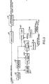
- That scrambled video signal may be descrambled in the descrambler circuit of the invention, an embodiment of which is illustrated schematically in Fig. 4.
- the circuit of Fig. 4 recovers the vertical and horizontal timing signals based respectively on the detection of the absence of color burst and then the occurrence of color burst after its absence for a predetermined interval or number of lines.
- the scrambled sync-suppressed video signal is applied to the descrambler circuit of Fig. 4 at a scrambled video input terminal 36, which is connected to the input of a variable attenuator 38.
- the latter also receives an attenuation control signal, which, when low, causes attenuator 38 to produce less attenuation to the input scrambled video signal during the vertical and horizontal intervals, as compared to when the attenuation control signal is high.
- the descrambling operation of attenuator 38 in the descrambling circuit of Fig. 4 is opposite to the scrambling operation carried out in the variable attenuator 14 in the scrambling circuit of Fig. 3.
- the descrambled video is applied to a video demodulator 40, which removes the rf carrier and supplies a descrambled video baseband signal to the video output terminal 42.
- the attenuation control signal applied to the variable attenuator 38 and which is low during the horizontal and vertical intervals is produced by the remainder of the timing generator circuit Fig. 4.
- Fig. 1 it will be noted that color burst is not present in lines 1-9 of field 1, for example, and reoccurs at line 10.
- the detection of color burst following the absence of color burst for a certain interval identifies the occurrence of a vertical interval, which is then employed to develop the horizontal and vertical interval pulses.
- the demodulated video output of video demodulator 40 is applied to a detector 44 tuned to the frequency of the color burst, 3.58 mHz, as well as to the input of a sync edge detector 46.
- the output of color burst detector 44 is applied to an input of an AND gate 48 and to an input of an AND gate 50.
- the output of AND gate 48 is applied to the reset input of a burst absence/line counter 52.
- counter 52 When counter 52 reaches a count of 253 it provides a signal to the S terminal of a vertical interval flip-flop 54, the Q terminal of which is connected to the second input of AND gate 48.
- counter 52 When counter 52 reaches a count of 7 it applies a signal to the S terminal of color burst absence flip-flop 56, the Q terminal of which is applied to the second input of AND gate 50.
- the output of AND gate 50 when present, represents the first burst detect signal, which is applied to the start terminal of counter 52, to the R terminals of flip-flops 54 and 56, and to an input of a priority selection logic 60.
- the output of color burst detector 44 is also applied to one input of a load count number (#) 52 circuit 62, which, when it receives a signal from priority selection logic 60, loads a count of 52 into a one-line counter 64, which receives 7.2 mHz clock pulses from a clock pulse generator 70.
- the start input of one-line counter 64 is connected to the output of a load zero circuit 66, which receives inputs from the sync edge detector 46 and the priority selection logic 60.
- Counter 64 also receives an input from a load #66 logic circuit 68, which, in turn, also receives an input from priority selection logic 60.
- the #425 output of one-line counter 64 is applied to the start input of a horizontal interval counter 72, which also receives the 7.2 mHz clock pulses from clock pulse generator 70.
- the #95 output from counter 72 is applied as an input to load #66 logic 68, and the count #425 output of counter 64 is also applied as the clock input of burst absence/line counter 52.
- the output of counter 72 is applied to a decoder 74 and the #79 and #425 count signals are respectively applied to the S and R inputs of a flip-flop 76.
- the output of flip-flop 76 is applied as one input of an AND gate 78.
- the other input to AND gate 78 is the output of a flip-flop 80, which respectively receives at its S and R terminals the #12 and #253 decoded outputs of a decoder 82, which, in turn, receives an output from the burst absence/line counter 52.
- the low output of flip-flop 76 is the reconstituted horizontal interval whereas the low output of flip-flop 80 is the reconstituted vertical interval.
- the output of AND gate 78 which is applied to the variable attenuator 38 as the attenuation-control signal, is thus low during the horizontal and vertical intervals and high at other periods so that the input scrambled video is attenuated by a greater extent during the video portion than during the horizontal and vertical intervals, thereby to restore the suppressed sync intervals to their proper levels relative to the video.
- the resulting output of attenuator 38 is, as noted above, an unscrambled video signal, which is demodulated in demodulator 40 and applied to the output terminal 42.
- the priority selection logic 60 establishes the priority of operation of the descrambler circuit of Fig. 4. Namely, when a sync pulse is detected at detector 46, the priority selection logic 60 causes load zero logic 66 to load a zero count into counter 66, and disables load #52 logic 62 and load #66 logic 68. A second level of priority is the detection of color burst in the absence of a sync pulse at which time priority selection logic 60 enables load #52 logic 62 and disables load zero logic 66 and load #66 logic 68, whereby a count of 52 is loaded into counter 64.
- priority selection logic 60 In the absence of both sync and color burst, priority selection logic 60 enables only load #66 logic 68 to load a count of 66 into the counter 64, which continues then to free run until color burst or sync is detected. Although the details of priority selection circuit 60 are not specifically illustrated in Fig. 4, the design of a logic circuit that performs the specified functions is believed to be well within the skill of the average logic designer and is thus not further described.
- priority selection logic 60 causes load #66 logic 68 to load a count of 66 into counter 64 to preset that counter, which continues to free run until it receives a count of 425 at which time it starts counter 72 and provides a clock to counter 52.
- the latter counts the lines for which there is an absence of sync and color burst until, as shown, a line count of 7 is achieved, which is applied through burst absence detector 56 to gate 50.
- gate 50 provides a signal to first burst detector 58, which provides a burst detect signal to priority select logic 60, which then causes load #52 logic 62 preset counter 64 with a count of 52 to establish a count shortened by about 7.3 ⁇ s, which is equivalent to the time period between the falling output of the sync edge and the color burst, which when detected in the descrambler of the invention initiates the process of deriving the horizontal and vertical sync pulses.
- sync edge detector 46 When the sync pulse levels are restored to their proper levels as a result of the operation of attenuator 38, they are detected by sync edge detector 46, which produces a found sync signal, which through load zero logic 66 presets counter 64 to zero, which then counts toward 425 until the next sync pulse is detected.
- the descrambler circuit of the invention operates as a feedback loop to derive or recover previously suppressed sync timing information by the detection of color burst following the absence of color burst for a predetermined interval.
- the circuit of the invention thus permits recovery of a sync-suppressed signal without adding any other timing information to the sync-suppressed video signal and without transmitting any portion of the synchronizing signals "in the clear" or unsuppressed.
- lines of both fields 1 and 2 may be used to transmit data signals which modulate a 3.58 mHz carrier. Those signals may be detected by the a.m. color burst detector 44, which is used to detect color burst as described above.
- This data may be used, for example, to establish authorization or programming codes at the subscriber terminals, which permit the subscriber to descramble certain programming for which he or she is authorized to view.
Abstract
Description
- The present invention relates generally to television communication, and, more particularly, to an improved technique for recovering timing signals from a scrambled video signal.
- The economic viability of subscription or pay television is dependent on the ability of the transmitter to encode or scramble a television signal so that an unauthorized receiver, that is, one not equipped with a suitable descrambler, will not be able to receive a viewable television picture. Over the years many techniques have been devised to scramble and then descramble a television signal for this purpose as shown, for example, in U.S. Patent No. 4,222,068.
- One common technique that has been employed to scramble a video signal is to suppress the horizontal synchronization pulses below the average value of the video level. This causes the television receiver to attempt unsuccessfully to lock horizontally on random video peaks rather than on the horizontal synchronizing pulses. The loss of effective horizontal synchronizing pulses also prevents the receiver from properly utilizing the color burst signal associated with the horizontal synchronizing pulse so that the color reproduction is also faulty.
- In order for the receiver to be able to view the scrambled video signal, the suppressed synchronizing pulses must be recovered from the received video signal at the television receiver. Two techniques are commonly employed to allow the receiver to recover the suppressed sync and timing information. In one technique, a timing pulse is amplitude-modulated on the f.m. audio carrier, which is then detected in the audio portion of the receiver and used to generate the timing signals necessary to descramble the input scrambled video signal. In another known technique, some portion of the sync timing pulses, such as the vertical interval, is transmitted without suppression, that is, "in the clear". At the receiver the video portion phase locks to the clear or unsuppressed sync portion, thereby to create the required synchronizing and timing information.
- Both of these known techniques have one flaw in common in that in both the timing signals can be recovered with relative ease so that in each the scrambling can be overcome by a relatively simple modification at the receiver to foil the scrambling and allow the video signal to be viewed without payment of the subscription fees. The first-described technique also creates possible interference problems with adjacent channels and can degrade the video signal or the channel being viewed. The latter technique has the further disadvantage of requiring the transmission of a relatively high amount of power during the unsuppressed "in-the-clear" intervals.
- The present invention resides in the concept of a tuned detector detecting the presence of the color burst signal after a prior absence of color burst of a predetermined duration, the vertical interval being detected as the absence of color burst for a predetermined time interval, and horizontal sync information being detected by noting the first color burst after the vertical interval.
- As will be appreciated by those skilled in the art, the present invention provides a technique for recovering timing information from a scrambled video signal in a manner which is difficult to foil. Furthermore, when used in a CATV system, the invention enables the power requirement to be reduced by permitting more power to be concentrated in the video signal and not in the synchronizing pulses. Yet a further advantage of the present invention is that it enables a sync-suppressed scrambled video signal to be descrambled without the need to add additional timing information to the signal or to leave any portion of the sync pulses in the clear.
- The invention, together with features and advantages of the same, will be clearly understood from consideration of the following description of an exemplary embodiment of the invention comprised as a timing generator for sync-suppressed television signals, such embodiment being illustrated by reference to the accompanying drawings, in which:
- Figs. 1 and 2 are typical waveforms of
field 1 andfield 2 video signals for use in describing the operation of the hereinafter described embodiment of the present invention; - Fig. 3 is a block diagram of a video scrambler for producing a sync-suppressed scrambled video signal; and
- Fig. 4 is a schematic block diagram of a timing generator and descrambler in accordance with the present invention.
- Referring to the drawings, Figs. 1 and 2 respectively illustrate
fields field 1 starts afterline 525 and includes a horizontal interval followed by video. The horizontal blanking interval includes a front porch, and a horizontal signal pulse followed by a back porch, which carries on it a color burst signal typically at a frequency of 3.58 mHz.Lines 1 through 21 offield 1 constitute a vertical interval, which includes vertical synchronization information that typically includes equalizing pulses and vertical synchronizing pulses followed by additional equalizing pulses. The vertical synchronization information is typically followed by horizontal trace lines, which are separated by horizontal blanking pulses, which, as in theprevious line 525, contain horizontal synchronizing pulses. Lines 22-262 offield 1 include horizontal blanking and synchronizing pulses and, of course, the video signals for each line. - As shown in Fig. 2,
field 2 begins with a vertical interval betweenlines 263 through 284, the latter also including a half line of video, which is, in turn, followed by lines 285-524, which contain horizontal blanking and synchronizing signals and the video portion of each of these lines. When combined in an interlaced fashion,fields - The timing generator of the present invention descrambles a scrambled television signal in which the horizontal and vertical synchronizing information is suppressed below the level of video such that the receiver is unable to lock onto a synchronizing signal, thereby rendering the received image unviewable.
- A circuit capable of scrambling an unscrambled video signal by suppressing the synchronizing signals is illustrated in Fig. 3. As therein shown the clear video signal is applied at a
video input terminal 10 and then to the input of amodulator 12. The output ofmodulator 12 is connected to the input of avariable attenuator 14, which also receives an attenuation control signal that establishes the amount of attenuation to the modulated video signal caused by theattenuator 14. As described below, the control signal is caused to be high during the horizontal and vertical synchronizing intervals, but not during video, so that the output of thevariable attenuator 14 is suppressed during those intervals and the output of the attenuator is a scrambled sync-suppressed video signal. - To this end, the clear or unscrambled video signal is applied to a
sync stripper 16 in which the sync signal is stripped from the video and is applied to the inputs of async edge detector 18 and ahalf line detector 20. The latter detects the beginning of a vertical interval for each field and applies its output as a start signal to a divide-by-256counter 22. - The output of the
sync edge detector 18 is applied as the clock input to counter 22 as well as to the clock input of a divide-by-32counter 24. The latter also receives the output ofcounter 22 as its start input. The output ofcounter 24 is applied to adecoder 26, which provides an output pulse corresponding to the vertical interval or lines 1-21 offield 1 andlines 263 through 284 offield 2. - The output of
sync edge detector 18 is also applied to the start input of a divide-by-900counter 28, which also receives clock signals at a rate of 14.3 mHz. The output ofcounter 28 is decoded in adecoder 30, which, produces a horizontal interval pulse. The latter along with the vertical interval pulse produced bydecoder 26 are applied to the inputs of anOR gate 32, the output of which is high during only the horizontal and vertical intervals, and constitutes the attenuation control signal applied to the control input ofvariable attenuator 14. The output ofattenuator 14 is thus, as noted previously, a scrambled video signal in which the levels of the horizontal and vertical synchronizing signals are suppressed. In the event of the transmission of a black-and-white signal, a simulated color burst signal may be added to the scrambled video output signal by suitable circuitry not shown in Fig. 3. - That scrambled video signal may be descrambled in the descrambler circuit of the invention, an embodiment of which is illustrated schematically in Fig. 4. Broadly described the circuit of Fig. 4 recovers the vertical and horizontal timing signals based respectively on the detection of the absence of color burst and then the occurrence of color burst after its absence for a predetermined interval or number of lines.
- The scrambled sync-suppressed video signal is applied to the descrambler circuit of Fig. 4 at a scrambled
video input terminal 36, which is connected to the input of avariable attenuator 38. The latter also receives an attenuation control signal, which, when low, causesattenuator 38 to produce less attenuation to the input scrambled video signal during the vertical and horizontal intervals, as compared to when the attenuation control signal is high. As will be appreciated, the descrambling operation ofattenuator 38 in the descrambling circuit of Fig. 4 is opposite to the scrambling operation carried out in thevariable attenuator 14 in the scrambling circuit of Fig. 3. The descrambled video is applied to avideo demodulator 40, which removes the rf carrier and supplies a descrambled video baseband signal to thevideo output terminal 42. - The attenuation control signal applied to the
variable attenuator 38 and which is low during the horizontal and vertical intervals is produced by the remainder of the timing generator circuit Fig. 4. First, however, referring to Fig. 1, it will be noted that color burst is not present in lines 1-9 offield 1, for example, and reoccurs atline 10. Thus, the detection of color burst following the absence of color burst for a certain interval identifies the occurrence of a vertical interval, which is then employed to develop the horizontal and vertical interval pulses. To this end, the demodulated video output ofvideo demodulator 40 is applied to adetector 44 tuned to the frequency of the color burst, 3.58 mHz, as well as to the input of async edge detector 46. The output ofcolor burst detector 44 is applied to an input of anAND gate 48 and to an input of anAND gate 50. - The output of
AND gate 48 is applied to the reset input of a burst absence/line counter 52. Whencounter 52 reaches a count of 253 it provides a signal to the S terminal of a vertical interval flip-flop 54, the Q terminal of which is connected to the second input ofAND gate 48. Whencounter 52 reaches a count of 7 it applies a signal to the S terminal of color burst absence flip-flop 56, the Q terminal of which is applied to the second input ofAND gate 50. - The output of
AND gate 50, when present, represents the first burst detect signal, which is applied to the start terminal ofcounter 52, to the R terminals of flip-flops 54 and 56, and to an input of apriority selection logic 60. The output ofcolor burst detector 44 is also applied to one input of a load count number (#) 52circuit 62, which, when it receives a signal frompriority selection logic 60, loads a count of 52 into a one-line counter 64, which receives 7.2 mHz clock pulses from aclock pulse generator 70. - The start input of one-
line counter 64 is connected to the output of aload zero circuit 66, which receives inputs from thesync edge detector 46 and thepriority selection logic 60.Counter 64 also receives an input from aload # 66logic circuit 68, which, in turn, also receives an input frompriority selection logic 60. Whencounter 64 is counting, it supplies a counter active signal topriority selection logic 60. In addition, the #425 output of one-line counter 64 is applied to the start input of ahorizontal interval counter 72, which also receives the 7.2 mHz clock pulses fromclock pulse generator 70. The #95 output fromcounter 72 is applied as an input to load #66logic 68, and thecount # 425 output ofcounter 64 is also applied as the clock input of burst absence/line counter 52. - The output of
counter 72 is applied to adecoder 74 and the #79 and #425 count signals are respectively applied to the S and R inputs of a flip-flop 76. The output of flip-flop 76 is applied as one input of an ANDgate 78. The other input to ANDgate 78 is the output of a flip-flop 80, which respectively receives at its S and R terminals the #12 and #253 decoded outputs of adecoder 82, which, in turn, receives an output from the burst absence/line counter 52. - The low output of flip-flop 76 is the reconstituted horizontal interval whereas the low output of flip-
flop 80 is the reconstituted vertical interval. The output of ANDgate 78, which is applied to thevariable attenuator 38 as the attenuation-control signal, is thus low during the horizontal and vertical intervals and high at other periods so that the input scrambled video is attenuated by a greater extent during the video portion than during the horizontal and vertical intervals, thereby to restore the suppressed sync intervals to their proper levels relative to the video. The resulting output ofattenuator 38 is, as noted above, an unscrambled video signal, which is demodulated indemodulator 40 and applied to theoutput terminal 42. - The
priority selection logic 60 establishes the priority of operation of the descrambler circuit of Fig. 4. Namely, when a sync pulse is detected atdetector 46, thepriority selection logic 60 causes load zerologic 66 to load a zero count intocounter 66, and disablesload # 52logic 62 andload # 66logic 68. A second level of priority is the detection of color burst in the absence of a sync pulse at which timepriority selection logic 60 enablesload # 52logic 62 and disables load zerologic 66 andload # 66logic 68, whereby a count of 52 is loaded intocounter 64. In the absence of both sync and color burst,priority selection logic 60 enables onlyload # 66logic 68 to load a count of 66 into thecounter 64, which continues then to free run until color burst or sync is detected. Although the details ofpriority selection circuit 60 are not specifically illustrated in Fig. 4, the design of a logic circuit that performs the specified functions is believed to be well within the skill of the average logic designer and is thus not further described. - Thus, when a scrambled video signal is received at
terminal 36, and when neither sync nor color burst is detected,priority selection logic 60 causes load #66logic 68 to load a count of 66 intocounter 64 to preset that counter, which continues to free run until it receives a count of 425 at which time it starts counter 72 and provides a clock to counter 52. The latter counts the lines for which there is an absence of sync and color burst until, as shown, a line count of 7 is achieved, which is applied throughburst absence detector 56 togate 50. - At the next occurrence of a color burst following at least a 7-line absence of color burst,
gate 50 provides a signal to first burst detector 58, which provides a burst detect signal to priorityselect logic 60, which then causesload # 52logic 62preset counter 64 with a count of 52 to establish a count shortened by about 7.3 µs, which is equivalent to the time period between the falling output of the sync edge and the color burst, which when detected in the descrambler of the invention initiates the process of deriving the horizontal and vertical sync pulses. When the sync pulse levels are restored to their proper levels as a result of the operation ofattenuator 38, they are detected bysync edge detector 46, which produces a found sync signal, which through load zerologic 66 presets counter 64 to zero, which then counts toward 425 until the next sync pulse is detected. - It will thus be appreciated that the descrambler circuit of the invention operates as a feedback loop to derive or recover previously suppressed sync timing information by the detection of color burst following the absence of color burst for a predetermined interval. The circuit of the invention thus permits recovery of a sync-suppressed signal without adding any other timing information to the sync-suppressed video signal and without transmitting any portion of the synchronizing signals "in the clear" or unsuppressed.
- If desired, lines of both
fields color burst detector 44, which is used to detect color burst as described above. This data may be used, for example, to establish authorization or programming codes at the subscriber terminals, which permit the subscriber to descramble certain programming for which he or she is authorized to view. Thus, it will be apparent that this and other modifications may be made to the specific embodiment of the invention described hereinabove, without necessarily departing from the scope of the invention as defined by the appended claims.
Claims (10)
Priority Applications (1)
| Application Number | Priority Date | Filing Date | Title |
|---|---|---|---|
| AT84303941T ATE63026T1 (en) | 1983-06-10 | 1984-06-11 | CLOCK GENERATOR FOR TELEVISION SIGNALS WITH SUPPRESSED SYNCHRONIZATION. |
Applications Claiming Priority (2)
| Application Number | Priority Date | Filing Date | Title |
|---|---|---|---|
| US06/502,933 US4571615A (en) | 1983-06-10 | 1983-06-10 | Timing generator for sync suppressed television signals |
| US502933 | 1983-06-10 |
Publications (3)
| Publication Number | Publication Date |
|---|---|
| EP0128771A2 true EP0128771A2 (en) | 1984-12-19 |
| EP0128771A3 EP0128771A3 (en) | 1986-09-03 |
| EP0128771B1 EP0128771B1 (en) | 1991-04-24 |
Family
ID=24000030
Family Applications (1)
| Application Number | Title | Priority Date | Filing Date |
|---|---|---|---|
| EP84303941A Expired - Lifetime EP0128771B1 (en) | 1983-06-10 | 1984-06-11 | Timing generator for sync suppressed television signals |
Country Status (10)
| Country | Link |
|---|---|
| US (1) | US4571615A (en) |
| EP (1) | EP0128771B1 (en) |
| JP (1) | JPS6019381A (en) |
| AT (1) | ATE63026T1 (en) |
| AU (1) | AU564501B2 (en) |
| CA (1) | CA1218143A (en) |
| DE (1) | DE3484484D1 (en) |
| IE (1) | IE57016B1 (en) |
| MX (1) | MX157762A (en) |
| NZ (1) | NZ208427A (en) |
Cited By (15)
| Publication number | Priority date | Publication date | Assignee | Title |
|---|---|---|---|---|
| US5442700A (en) * | 1990-09-28 | 1995-08-15 | Ictv, Inc. | Scrambling method |
| EP0856224A1 (en) * | 1995-10-17 | 1998-08-05 | Macrovision Corporation | Method and apparatus for removing or defeating effects of copy protection signals from a video signal |
| US9021541B2 (en) | 2010-10-14 | 2015-04-28 | Activevideo Networks, Inc. | Streaming digital video between video devices using a cable television system |
| US9042454B2 (en) | 2007-01-12 | 2015-05-26 | Activevideo Networks, Inc. | Interactive encoded content system including object models for viewing on a remote device |
| US9077860B2 (en) | 2005-07-26 | 2015-07-07 | Activevideo Networks, Inc. | System and method for providing video content associated with a source image to a television in a communication network |
| US9123084B2 (en) | 2012-04-12 | 2015-09-01 | Activevideo Networks, Inc. | Graphical application integration with MPEG objects |
| US9204203B2 (en) | 2011-04-07 | 2015-12-01 | Activevideo Networks, Inc. | Reduction of latency in video distribution networks using adaptive bit rates |
| US9219922B2 (en) | 2013-06-06 | 2015-12-22 | Activevideo Networks, Inc. | System and method for exploiting scene graph information in construction of an encoded video sequence |
| US9294785B2 (en) | 2013-06-06 | 2016-03-22 | Activevideo Networks, Inc. | System and method for exploiting scene graph information in construction of an encoded video sequence |
| US9326047B2 (en) | 2013-06-06 | 2016-04-26 | Activevideo Networks, Inc. | Overlay rendering of user interface onto source video |
| US9788029B2 (en) | 2014-04-25 | 2017-10-10 | Activevideo Networks, Inc. | Intelligent multiplexing using class-based, multi-dimensioned decision logic for managed networks |
| US9800945B2 (en) | 2012-04-03 | 2017-10-24 | Activevideo Networks, Inc. | Class-based intelligent multiplexing over unmanaged networks |
| US9826197B2 (en) | 2007-01-12 | 2017-11-21 | Activevideo Networks, Inc. | Providing television broadcasts over a managed network and interactive content over an unmanaged network to a client device |
| US10275128B2 (en) | 2013-03-15 | 2019-04-30 | Activevideo Networks, Inc. | Multiple-mode system and method for providing user selectable video content |
| US10409445B2 (en) | 2012-01-09 | 2019-09-10 | Activevideo Networks, Inc. | Rendering of an interactive lean-backward user interface on a television |
Families Citing this family (13)
| Publication number | Priority date | Publication date | Assignee | Title |
|---|---|---|---|---|
| US4817142A (en) * | 1985-05-21 | 1989-03-28 | Scientific Atlanta, Inc. | Restoring framing in a communications system |
| CA1292056C (en) * | 1987-09-07 | 1991-11-12 | Masatoshi Tanaka | Video signal scrambling system |
| US4920566A (en) * | 1989-02-01 | 1990-04-24 | General Instrument Corporation | Dual loop sinewave descrambler and method of descrambling |
| US4928309A (en) * | 1989-03-31 | 1990-05-22 | General Instrument Corporation | Method and apparatus for descrambling a television signal |
| JP2810103B2 (en) * | 1989-04-28 | 1998-10-15 | パイオニア株式会社 | How to scramble television signals |
| CA2020313C (en) * | 1989-07-21 | 1996-06-11 | Ralph P. Harney | Universal decoder |
| US5173775A (en) * | 1991-05-02 | 1992-12-22 | General Instrument Corporation | Reformatting of television signal data for transmission using a different modulation scheme |
| US5146496A (en) * | 1991-06-13 | 1992-09-08 | General Instrument Corporation | Method and apparatus for enhancing the security of a scrambled television signal |
| EP0518128A3 (en) * | 1991-06-13 | 1993-03-17 | General Instrument Corporation | Method and apparatus for frustrating vertical interval detection in scrambled television signals |
| US6327422B1 (en) * | 1997-07-18 | 2001-12-04 | Macrovision Corp | Method and apparatus for modifying the effects of color burst modifications to a video signal |
| ATE207274T1 (en) * | 1995-05-09 | 2001-11-15 | Macrovision Corp | METHOD AND APPARATUS FOR ELIMINating THE CONSEQUENCES OF CHANGE IN THE COLOR BURST SIGNAL IN A TELEVISION SIGNAL |
| US6529248B1 (en) * | 2000-03-29 | 2003-03-04 | Zilog, Inc. | Method and apparatus for improved signal restoration |
| US7526103B2 (en) * | 2004-04-15 | 2009-04-28 | Donnelly Corporation | Imaging system for vehicle |
Citations (1)
| Publication number | Priority date | Publication date | Assignee | Title |
|---|---|---|---|---|
| US4319273A (en) * | 1979-10-26 | 1982-03-09 | Rca Corporation | Television signal with encoded synchronizing signals |
Family Cites Families (2)
| Publication number | Priority date | Publication date | Assignee | Title |
|---|---|---|---|---|
| CA1153103A (en) * | 1981-03-19 | 1983-08-30 | Northern Telecom Limited | Scrambling and unscrambling video signals in a pay tv system |
| CA1150821A (en) * | 1981-03-19 | 1983-07-26 | Northern Telecom Limited | Transmission of data with a video signal |
-
1983
- 1983-06-10 US US06/502,933 patent/US4571615A/en not_active Expired - Lifetime
-
1984
- 1984-06-08 AU AU29312/84A patent/AU564501B2/en not_active Ceased
- 1984-06-08 NZ NZ208427A patent/NZ208427A/en unknown
- 1984-06-08 CA CA000456193A patent/CA1218143A/en not_active Expired
- 1984-06-08 MX MX201587A patent/MX157762A/en unknown
- 1984-06-08 IE IE1446/84A patent/IE57016B1/en not_active IP Right Cessation
- 1984-06-11 EP EP84303941A patent/EP0128771B1/en not_active Expired - Lifetime
- 1984-06-11 DE DE8484303941T patent/DE3484484D1/en not_active Expired - Lifetime
- 1984-06-11 JP JP59118362A patent/JPS6019381A/en active Pending
- 1984-06-11 AT AT84303941T patent/ATE63026T1/en not_active IP Right Cessation
Patent Citations (1)
| Publication number | Priority date | Publication date | Assignee | Title |
|---|---|---|---|---|
| US4319273A (en) * | 1979-10-26 | 1982-03-09 | Rca Corporation | Television signal with encoded synchronizing signals |
Cited By (23)
| Publication number | Priority date | Publication date | Assignee | Title |
|---|---|---|---|---|
| US5442700A (en) * | 1990-09-28 | 1995-08-15 | Ictv, Inc. | Scrambling method |
| EP0856224A1 (en) * | 1995-10-17 | 1998-08-05 | Macrovision Corporation | Method and apparatus for removing or defeating effects of copy protection signals from a video signal |
| EP0856224A4 (en) * | 1995-10-17 | 1998-11-25 | Macrovision Corp | Method and apparatus for removing or defeating effects of copy protection signals from a video signal |
| EP1646234A2 (en) * | 1995-10-17 | 2006-04-12 | Macrovision Corporation | Method and apparatus for removing or defeating effects of copy protection signals from a video signal |
| EP1646234A3 (en) * | 1995-10-17 | 2010-11-24 | Macrovision Corporation | Method and apparatus for removing or defeating effects of copy protection signals from a video signal |
| US9077860B2 (en) | 2005-07-26 | 2015-07-07 | Activevideo Networks, Inc. | System and method for providing video content associated with a source image to a television in a communication network |
| US9355681B2 (en) | 2007-01-12 | 2016-05-31 | Activevideo Networks, Inc. | MPEG objects and systems and methods for using MPEG objects |
| US9042454B2 (en) | 2007-01-12 | 2015-05-26 | Activevideo Networks, Inc. | Interactive encoded content system including object models for viewing on a remote device |
| US9826197B2 (en) | 2007-01-12 | 2017-11-21 | Activevideo Networks, Inc. | Providing television broadcasts over a managed network and interactive content over an unmanaged network to a client device |
| US9021541B2 (en) | 2010-10-14 | 2015-04-28 | Activevideo Networks, Inc. | Streaming digital video between video devices using a cable television system |
| US9204203B2 (en) | 2011-04-07 | 2015-12-01 | Activevideo Networks, Inc. | Reduction of latency in video distribution networks using adaptive bit rates |
| US10409445B2 (en) | 2012-01-09 | 2019-09-10 | Activevideo Networks, Inc. | Rendering of an interactive lean-backward user interface on a television |
| US9800945B2 (en) | 2012-04-03 | 2017-10-24 | Activevideo Networks, Inc. | Class-based intelligent multiplexing over unmanaged networks |
| US10506298B2 (en) | 2012-04-03 | 2019-12-10 | Activevideo Networks, Inc. | Class-based intelligent multiplexing over unmanaged networks |
| US10757481B2 (en) | 2012-04-03 | 2020-08-25 | Activevideo Networks, Inc. | Class-based intelligent multiplexing over unmanaged networks |
| US9123084B2 (en) | 2012-04-12 | 2015-09-01 | Activevideo Networks, Inc. | Graphical application integration with MPEG objects |
| US10275128B2 (en) | 2013-03-15 | 2019-04-30 | Activevideo Networks, Inc. | Multiple-mode system and method for providing user selectable video content |
| US11073969B2 (en) | 2013-03-15 | 2021-07-27 | Activevideo Networks, Inc. | Multiple-mode system and method for providing user selectable video content |
| US9326047B2 (en) | 2013-06-06 | 2016-04-26 | Activevideo Networks, Inc. | Overlay rendering of user interface onto source video |
| US9294785B2 (en) | 2013-06-06 | 2016-03-22 | Activevideo Networks, Inc. | System and method for exploiting scene graph information in construction of an encoded video sequence |
| US9219922B2 (en) | 2013-06-06 | 2015-12-22 | Activevideo Networks, Inc. | System and method for exploiting scene graph information in construction of an encoded video sequence |
| US10200744B2 (en) | 2013-06-06 | 2019-02-05 | Activevideo Networks, Inc. | Overlay rendering of user interface onto source video |
| US9788029B2 (en) | 2014-04-25 | 2017-10-10 | Activevideo Networks, Inc. | Intelligent multiplexing using class-based, multi-dimensioned decision logic for managed networks |
Also Published As
| Publication number | Publication date |
|---|---|
| IE841446L (en) | 1984-12-10 |
| ATE63026T1 (en) | 1991-05-15 |
| DE3484484D1 (en) | 1991-05-29 |
| AU2931284A (en) | 1984-12-13 |
| MX157762A (en) | 1988-12-13 |
| NZ208427A (en) | 1987-07-31 |
| US4571615A (en) | 1986-02-18 |
| EP0128771B1 (en) | 1991-04-24 |
| AU564501B2 (en) | 1987-08-13 |
| IE57016B1 (en) | 1992-03-11 |
| EP0128771A3 (en) | 1986-09-03 |
| JPS6019381A (en) | 1985-01-31 |
| CA1218143A (en) | 1987-02-17 |
Similar Documents
| Publication | Publication Date | Title |
|---|---|---|
| US4571615A (en) | Timing generator for sync suppressed television signals | |
| US4389671A (en) | Digitally-controlled analog encrypton | |
| US4523228A (en) | Sync suppression scrambling of television signals for subscription TV | |
| CA1186793A (en) | Scrambling and descrambling of television signals for subscription tv | |
| US4222068A (en) | Subscription television apparatus and methods | |
| EP0099691B1 (en) | Method for encrypting a line-scanned television signal and encrypting and decrypting apparatus | |
| US4562465A (en) | Adaptive video descrambling system | |
| CA1123949A (en) | High security subscription television system employing real time control of subscriber's program reception | |
| US4817142A (en) | Restoring framing in a communications system | |
| US3202758A (en) | Subscription-television programscrambling system | |
| US5651065A (en) | Insertion of supplemental burst into video signals to thwart piracy and/or carry data | |
| US4614970A (en) | Descrambler apparatus | |
| US4590519A (en) | Television signal scrambling/descrambling system | |
| EP0518129B1 (en) | Method and apparatus for enhancing the security of a scrambled television signal | |
| CA1205900A (en) | Scrambling system of television signal | |
| US4691353A (en) | Scrambling systems for CATV | |
| US6028941A (en) | Method for the defeat of illegal descramblers sensitive to the edges of sync in scrambled video | |
| US5287409A (en) | Method and apparatus for frustrating vertical interval detection in scrambled television signals | |
| CA1204162A (en) | Audio scrambler utilizing an auxiliary channel for synchronizing the descrambler | |
| US4807285A (en) | Method and apparatus for scrambling a television signal | |
| US5912970A (en) | Television scrambling system | |
| JPH0143514B2 (en) | ||
| CA1256198A (en) | Descrambler apparatus | |
| CA1149052A (en) | Subscription television apparatus and methods | |
| WO1984003811A1 (en) | Compatible descrambler for television synchronization |
Legal Events
| Date | Code | Title | Description |
|---|---|---|---|
| PUAI | Public reference made under article 153(3) epc to a published international application that has entered the european phase |
Free format text: ORIGINAL CODE: 0009012 |
|
| AK | Designated contracting states |
Designated state(s): AT BE CH DE FR GB IT LI SE |
|
| PUAL | Search report despatched |
Free format text: ORIGINAL CODE: 0009013 |
|
| AK | Designated contracting states |
Kind code of ref document: A3 Designated state(s): AT BE CH DE FR GB IT LI SE |
|
| 17P | Request for examination filed |
Effective date: 19861103 |
|
| 17Q | First examination report despatched |
Effective date: 19880715 |
|
| GRAA | (expected) grant |
Free format text: ORIGINAL CODE: 0009210 |
|
| AK | Designated contracting states |
Kind code of ref document: B1 Designated state(s): AT BE CH DE FR GB IT LI SE |
|
| REF | Corresponds to: |
Ref document number: 63026 Country of ref document: AT Date of ref document: 19910515 Kind code of ref document: T |
|
| ITF | It: translation for a ep patent filed |
Owner name: ING. A. GIAMBROCONO & C. S.R.L. |
|
| REF | Corresponds to: |
Ref document number: 3484484 Country of ref document: DE Date of ref document: 19910529 |
|
| ET | Fr: translation filed | ||
| PLBE | No opposition filed within time limit |
Free format text: ORIGINAL CODE: 0009261 |
|
| STAA | Information on the status of an ep patent application or granted ep patent |
Free format text: STATUS: NO OPPOSITION FILED WITHIN TIME LIMIT |
|
| 26N | No opposition filed | ||
| EAL | Se: european patent in force in sweden |
Ref document number: 84303941.3 |
|
| PGFP | Annual fee paid to national office [announced via postgrant information from national office to epo] |
Ref country code: SE Payment date: 19980522 Year of fee payment: 15 |
|
| PGFP | Annual fee paid to national office [announced via postgrant information from national office to epo] |
Ref country code: AT Payment date: 19980526 Year of fee payment: 15 |
|
| PGFP | Annual fee paid to national office [announced via postgrant information from national office to epo] |
Ref country code: CH Payment date: 19980528 Year of fee payment: 15 |
|
| PGFP | Annual fee paid to national office [announced via postgrant information from national office to epo] |
Ref country code: BE Payment date: 19980615 Year of fee payment: 15 |
|
| REG | Reference to a national code |
Ref country code: GB Ref legal event code: 732E |
|
| REG | Reference to a national code |
Ref country code: FR Ref legal event code: TP |
|
| REG | Reference to a national code |
Ref country code: FR Ref legal event code: TP |
|
| REG | Reference to a national code |
Ref country code: CH Ref legal event code: PUE Owner name: GENERAL INSTRUMENT CORPORATION TRANSFER- GENERAL I |
|
| PG25 | Lapsed in a contracting state [announced via postgrant information from national office to epo] |
Ref country code: AT Free format text: LAPSE BECAUSE OF NON-PAYMENT OF DUE FEES Effective date: 19990611 |
|
| PG25 | Lapsed in a contracting state [announced via postgrant information from national office to epo] |
Ref country code: SE Free format text: THE PATENT HAS BEEN ANNULLED BY A DECISION OF A NATIONAL AUTHORITY Effective date: 19990629 |
|
| PG25 | Lapsed in a contracting state [announced via postgrant information from national office to epo] |
Ref country code: LI Free format text: LAPSE BECAUSE OF NON-PAYMENT OF DUE FEES Effective date: 19990630 Ref country code: CH Free format text: LAPSE BECAUSE OF NON-PAYMENT OF DUE FEES Effective date: 19990630 Ref country code: BE Free format text: LAPSE BECAUSE OF NON-PAYMENT OF DUE FEES Effective date: 19990630 |
|
| BERE | Be: lapsed |
Owner name: GENERAL INSTRUMENT CORP. Effective date: 19990630 |
|
| REG | Reference to a national code |
Ref country code: CH Ref legal event code: PL |
|
| EUG | Se: european patent has lapsed |
Ref document number: 84303941.3 |
|
| PGFP | Annual fee paid to national office [announced via postgrant information from national office to epo] |
Ref country code: GB Payment date: 20010502 Year of fee payment: 18 |
|
| PGFP | Annual fee paid to national office [announced via postgrant information from national office to epo] |
Ref country code: FR Payment date: 20010531 Year of fee payment: 18 |
|
| PGFP | Annual fee paid to national office [announced via postgrant information from national office to epo] |
Ref country code: DE Payment date: 20010627 Year of fee payment: 18 |
|
| REG | Reference to a national code |
Ref country code: GB Ref legal event code: IF02 |
|
| PG25 | Lapsed in a contracting state [announced via postgrant information from national office to epo] |
Ref country code: GB Free format text: LAPSE BECAUSE OF NON-PAYMENT OF DUE FEES Effective date: 20020611 |
|
| PG25 | Lapsed in a contracting state [announced via postgrant information from national office to epo] |
Ref country code: DE Free format text: LAPSE BECAUSE OF NON-PAYMENT OF DUE FEES Effective date: 20030101 |
|
| GBPC | Gb: european patent ceased through non-payment of renewal fee |
Effective date: 20020611 |
|
| PG25 | Lapsed in a contracting state [announced via postgrant information from national office to epo] |
Ref country code: FR Free format text: LAPSE BECAUSE OF NON-PAYMENT OF DUE FEES Effective date: 20030228 |
|
| REG | Reference to a national code |
Ref country code: FR Ref legal event code: ST |
|
| P01 | Opt-out of the competence of the unified patent court (upc) registered |
Effective date: 20230520 |