EP0129042A2 - Method of modifying a closure member equipped with a latch or a key-operated lock and unit for use in the method - Google Patents
Method of modifying a closure member equipped with a latch or a key-operated lock and unit for use in the method Download PDFInfo
- Publication number
- EP0129042A2 EP0129042A2 EP84105290A EP84105290A EP0129042A2 EP 0129042 A2 EP0129042 A2 EP 0129042A2 EP 84105290 A EP84105290 A EP 84105290A EP 84105290 A EP84105290 A EP 84105290A EP 0129042 A2 EP0129042 A2 EP 0129042A2
- Authority
- EP
- European Patent Office
- Prior art keywords
- key
- control unit
- closure member
- lock
- control rod
- Prior art date
- Legal status (The legal status is an assumption and is not a legal conclusion. Google has not performed a legal analysis and makes no representation as to the accuracy of the status listed.)
- Withdrawn
Links
Images
Classifications
-
- G—PHYSICS
- G07—CHECKING-DEVICES
- G07C—TIME OR ATTENDANCE REGISTERS; REGISTERING OR INDICATING THE WORKING OF MACHINES; GENERATING RANDOM NUMBERS; VOTING OR LOTTERY APPARATUS; ARRANGEMENTS, SYSTEMS OR APPARATUS FOR CHECKING NOT PROVIDED FOR ELSEWHERE
- G07C9/00—Individual registration on entry or exit
- G07C9/00174—Electronically operated locks; Circuits therefor; Nonmechanical keys therefor, e.g. passive or active electrical keys or other data carriers without mechanical keys
- G07C9/00658—Electronically operated locks; Circuits therefor; Nonmechanical keys therefor, e.g. passive or active electrical keys or other data carriers without mechanical keys operated by passive electrical keys
- G07C9/00722—Electronically operated locks; Circuits therefor; Nonmechanical keys therefor, e.g. passive or active electrical keys or other data carriers without mechanical keys operated by passive electrical keys with magnetic components, e.g. magnets, magnetic strips, metallic inserts
- G07C9/00738—Electronically operated locks; Circuits therefor; Nonmechanical keys therefor, e.g. passive or active electrical keys or other data carriers without mechanical keys operated by passive electrical keys with magnetic components, e.g. magnets, magnetic strips, metallic inserts sensed by Hall effect devices
Definitions
- a first aspect of the present invention relates to a method of modifying a combination comprising a closure member and a key-operated lock for locking the closure member in a closed position.
- the invention is especially useful in hotels where the bedroom doors are equipped with tumbler locks operated by keys which engage the tumblers and displace the tumblers to releasing positions.
- tumbler locks operated by keys which engage the tumblers and displace the tumblers to releasing positions.
- substitution of tumbler locks originally fitted to doors by such magnetic locks is expensive and generally inconvenient.
- modification of existing tumbler locks by removing the tumbler mechanism and substituting sensors responsive to a magnetic field is at least expensive and is often impracticable.
- a method of modifying a combination comprising a closure member and a key-operated lock for locking the closure member in a closed position, wherein the key is inserted into the lock to leave a handle of the key exposed outside the lock and a control unit is mounted on the closure member to cover the handle of the key whilst the key remains in the lock, the control unit having a body, an opening for receiving a coded element, a driving member and reading means responsive to insertion into the opening of an appropriate coded element to set the control unit in a driving condition, in which the control unit can rotate the key relative to the body, the key being coupled with the driving member for rotation therewith.
- an existing combination of a closure member and key-operated lock can be modified to permit control by a magnetically coded element without modification or replacement of the original lock.
- a method of modifying a combination comprising a closure member and a latch for holding the closure member in a closed position, wherein a handle of the latch is removed from the closure member to expose an end portion of a control rod which normally provides a connection between the handle and the latch, and a control unit is mounted on the closure member to cover the exposed end portion of the control rod, the control unit having a body, an opening for receiving a coded element, a driving member and reading means responsive to insertion into the opening of an appropriate coded element to set the control unit in a driving condition, in whch the control unit can rotate the control rod relative to the body, the control rod being coupled with the driving member for rotation therewith.
- a control unit for use in a method according to either of the first and second aspects of the invention, the unit comprising a body which, in use, is mounted fixedly on a closure member, a driving member adapted to receive a handle of the key or an end portion of the control rod in a manner to constrain the key or control rod to rotate relative to the body with the driving member and reading means adapted to respond to juxtaposition of a suitably coded element with the reading means to set the control unit in a driving condition, in which the unit can rotate the key or control rod relative to the body.
- the control unit preferably further includes an input element exposed at the outside of the body when the unit is in use and forming a part of, or being operatively associated with, the driving member to transmit drive from a user to the key or control rod.
- the user applies the torque which turns the key or control rod and unlocks the closure member.
- Electrical energy may be supplied to the control unit merely for operating the reading means. This energy may be derived from a primary cell or battery of cells incorporated in the control unit or may be supplied to the control unit from an external power source..
- the reading means is preferably responsive to a field associated with the coded element and may include Hall effect devices which respond to a magnetic field of the coded element.
- control unit in accordance with the invention will now be described, with reference to the accompanying drawing, wherein there is shown diagrammatically a part of a door fitted with a tumbler lock, a control unit and a coded element for use with the control unit.
- a closure member which may be the door of a room.
- a lock 11 having a bolt (not shown) and a tumbler mechanism (also not shown).
- a key-receiving slot of the lock At an outer face of the door, there is an open end of a key-receiving slot of the lock.
- a key is shown inserted into the lock from the outside of the door, a handle 12 of the key remaining outside the lock.
- the tumbler mechanism can be operated to withdraw the bolt into the door.
- the bolt can also be withdrawn into the door by operation of a handle 13 provided at the inner face of the door.
- the door is a sliding door and the lock is adapted to prevent sliding from a closed position.
- control unit 14 having a body 15 which is adapted to be mounted by means of fasteners (not shown) on the door 10 in a manner such that the fasteners are not accessible at the outside of the door. In this way, the body 15 is rigidly secured to the door.
- the driving member includes an input element 18 which is exposed outside the body 15 and can readily be grasped by a user.
- the remainder of the driving member is disposed within the body 15 and is formed with an opening which can receive the handle 12 of the key with a small clearance.
- the driving member is adapted to transmit torque to the key to rotate the latter about the axis 16.
- the key handle 12 is flat and the opening in the driving member 17 is a parallel-sided slot having opposite boundaries engageable with the flat faces of the key handle.
- the bolt is guided by the body 15 for sliding along a rectilinear path towards and away from the axis 16 and is urged towards that axis relative to the body by a bolt spring 20.
- An end portion of the holt which is nearer to the axis 16 can ent p r a recess in the driving member 17 tn hrinq into contact with a boundary of that recess an end face of the bolt. This end face lies in a plane perpendicular to the direction of movement of the bolt and parallel to the axis 16.
- a detent 21 which is engageable in a notch formed in the bolt and is movable out of that notch in a direction parallel to the axis 16.
- the detent is guided by the body 15 and is controlled by a springloaded solenoid 22 also contained within the body.
- the body 15 defines a slot 23 which is open at the exterior of the body and through which a major part of a coded element 24 can be inserted into the body along a predetermined rectilinear path. Adjacent to this path, there is provided in the body a number of sensors 25 capable of responding to a field associated with the coded element 24. Some of the sensors are omitted from the drawinq.
- the element 24 includes a layer of magnetic material having a number of magnetic poles which are presented towards the sensors 25 when the coded element is inserted into the body 15.
- the sensors are Hall effect devices arranged to provide respective electrical output signals when subjected to a magnetic field having sufficient strength.
- the magnetic poles of the element 24 are positioned in accordance with a code. Typically, three or four poles may be present at one face of the coded element.
- a larger number of sensors 25 are provided in the body 15 but only some of these respond to the insertion of the element 24. Output signals from the sensors 25 are fed to a logic circuit (not shown) which controls energisation of the solenoid 22. Electrical energy for operation of the sensors 25 and of the solenoid 22 is derived either from a cell or batteries (not shown) incorporated in the control unit 14, or from a remote power source connected by electrical conductors (also not shown) with the control unit.
- the control unit is mounted on the door 10 in a position such that the axis 16 coincides with the axis of rotation of the key in the lock 11. Normally, the bolt 19 is in its locking position and prevents rotation of the key by means of the input element 18.
- the solenoid 23 is energised to withdraw the detent 21 from the notch in the bolt.
- the input element 18 can then be rotated to drive the bolt away from the axis 16 and to turn the key 12, thus unlocking the door.
- the solenoid is de-energised and the detent is urged against the bolt.
- the bolt spring 20 drives the bolt towards the axis 16 and the bolt rotates the driving member 17 to lock the door.
- a further spring which assists rotation of the key to lock the door. It will be noted that the control unit 14 prevents direct access to the key.
- the logic circuit of the control unit prevents energisation of the solenoid 22 and the control unit remains incapable of rotating the key 12 relative to the body 15.
- the coded element 24 may be in the form of a card, similar to a credit card and having a sandwich construction including at least one layer of magnetic material.
- the coded element may be a magnetic key, for example a key as disclosed in U.S. 4.112,292.
- the circuit which includes the Hall effect devices also may be as disclosed in U.S. 4,112,292.
- the reader and coded element may be as disclosed in G.B. 1,294,608.
- means is provided for releasably restraining rotation of the driving element and key.
- a clutch is provided for transmitting drive from the input element to the driving element and operation of the clutch is controlled by the sensors so that, unless an appropriately coded element is inserted into the unit, the input element can be rotated freely without accompanying rotation of the driving element and key.
- a latch normally includes a mechanism disposed within the closure member and handles mounted on the larger faces of the closure member, the handles and the mechanism being connected together by a control rod having a square cross- section. If one of the handles is removed from the closure member, an end portion of the control rod which projects from the closure member will be exposed, in a similar manner to that in which the handle 12 of the key is exposed in the method hereinbefore described.
- a control unit similar to the unit 14 can then be applied to the closure member to control operation of the latch. The driving member of this control unit would be adapted to .receive and to transmit torque to the exposed end portion of the control rod.
- the control unit may be identical with the unit 14 hereinbefore described.
Abstract
A lock (11) fitted to a door (10) is modified by inserting an appropriate key into the lock so that a handle (12) of the key protrudes from the lock and applying a control unit (14) to the door to cover and engage drivingly the handle of the key. The control unit is responsive to a magnetically coded key, by means of which the control unit can be set in a condition in which torque is transmitted from a knob (18) to the key.
Description
- A first aspect of the present invention relates to a method of modifying a combination comprising a closure member and a key-operated lock for locking the closure member in a closed position.
- The invention is especially useful in hotels where the bedroom doors are equipped with tumbler locks operated by keys which engage the tumblers and displace the tumblers to releasing positions. There are now available locks intended to be used with magnetically coded keys and having Hall effect devices or other sensors responsive to a magnetic field of the key to unlock a door. However, substitution of tumbler locks originally fitted to doors by such magnetic locks is expensive and generally inconvenient. Furthermore, modification of existing tumbler locks by removing the tumbler mechanism and substituting sensors responsive to a magnetic field is at least expensive and is often impracticable.
- According to the first aspect of the invention, there is provided a method of modifying a combination comprising a closure member and a key-operated lock for locking the closure member in a closed position, wherein the key is inserted into the lock to leave a handle of the key exposed outside the lock and a control unit is mounted on the closure member to cover the handle of the key whilst the key remains in the lock, the control unit having a body, an opening for receiving a coded element, a driving member and reading means responsive to insertion into the opening of an appropriate coded element to set the control unit in a driving condition, in which the control unit can rotate the key relative to the body, the key being coupled with the driving member for rotation therewith.
- By the method of the invention, an existing combination of a closure member and key-operated lock can be modified to permit control by a magnetically coded element without modification or replacement of the original lock.
- According to a second aspect of the invention, there is provided a method of modifying a combination comprising a closure member and a latch for holding the closure member in a closed position, wherein a handle of the latch is removed from the closure member to expose an end portion of a control rod which normally provides a connection between the handle and the latch, and a control unit is mounted on the closure member to cover the exposed end portion of the control rod, the control unit having a body, an opening for receiving a coded element, a driving member and reading means responsive to insertion into the opening of an appropriate coded element to set the control unit in a driving condition, in whch the control unit can rotate the control rod relative to the body, the control rod being coupled with the driving member for rotation therewith.
- According to a further aspect of the invention, there is provided a control unit for use in a method according to either of the first and second aspects of the invention, the unit comprising a body which, in use, is mounted fixedly on a closure member, a driving member adapted to receive a handle of the key or an end portion of the control rod in a manner to constrain the key or control rod to rotate relative to the body with the driving member and reading means adapted to respond to juxtaposition of a suitably coded element with the reading means to set the control unit in a driving condition, in which the unit can rotate the key or control rod relative to the body.
- The control unit preferably further includes an input element exposed at the outside of the body when the unit is in use and forming a part of, or being operatively associated with, the driving member to transmit drive from a user to the key or control rod. With this arrangement, the user applies the torque which turns the key or control rod and unlocks the closure member. Electrical energy may be supplied to the control unit merely for operating the reading means. This energy may be derived from a primary cell or battery of cells incorporated in the control unit or may be supplied to the control unit from an external power source..
- The reading means is preferably responsive to a field associated with the coded element and may include Hall effect devices which respond to a magnetic field of the coded element.
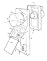
- An example of a control unit in accordance with the invention will now be described, with reference to the accompanying drawing, wherein there is shown diagrammatically a part of a door fitted with a tumbler lock, a control unit and a coded element for use with the control unit.
- There is represented at 10 in the drawing, a closure member which may be the door of a room. There is fitted in the closure member a
lock 11 having a bolt (not shown) and a tumbler mechanism (also not shown). At an outer face of the door, there is an open end of a key-receiving slot of the lock. A key is shown inserted into the lock from the outside of the door, ahandle 12 of the key remaining outside the lock. By means of the key, the tumbler mechanism can be operated to withdraw the bolt into the door. At least when the door has been unlocked by the key, the bolt can also be withdrawn into the door by operation of ahandle 13 provided at the inner face of the door. - The components described thus far with reference to the drawing may be constructed and arranged in a known manner. In an alternative arrangement, the door is a sliding door and the lock is adapted to prevent sliding from a closed position.
- There is provided for mounting on the door 10 a
control unit 14 having abody 15 which is adapted to be mounted by means of fasteners (not shown) on thedoor 10 in a manner such that the fasteners are not accessible at the outside of the door. In this way, thebody 15 is rigidly secured to the door. - There is mounted in the
body 15 for rotation relative thereto about an axis 16 adriving member 17. The driving member includes aninput element 18 which is exposed outside thebody 15 and can readily be grasped by a user. The remainder of the driving member is disposed within thebody 15 and is formed with an opening which can receive thehandle 12 of the key with a small clearance. The driving member is adapted to transmit torque to the key to rotate the latter about the axis 16. Typically, thekey handle 12 is flat and the opening in the drivingmember 17 is a parallel-sided slot having opposite boundaries engageable with the flat faces of the key handle. - There is also disposed within the
body 15 means, in the form of abolt 19; for restraining rotation of thedriving member 17. The bolt is guided by thebody 15 for sliding along a rectilinear path towards and away from the axis 16 and is urged towards that axis relative to the body by a bolt spring 20. An end portion of the holt which is nearer to the axis 16 can entpr a recess in the drivingmember 17 tn hrinq into contact with a boundary of that recess an end face of the bolt. This end face lies in a plane perpendicular to the direction of movement of the bolt and parallel to the axis 16. When the control unit is in the locked condition illustrated in the drawing, this end face of the bolt is in face-to-face contact with a corresponding flat boundary surface of the recess in the driving member. Rotation of the driving member about the axis 16 can then only occur if the bolt is free to move away from the axis 16. - For normally maintaining the
bolt 19 in the locking position shown in the drawing, there is provided a detent 21 which is engageable in a notch formed in the bolt and is movable out of that notch in a direction parallel to the axis 16. The detent is guided by thebody 15 and is controlled by a springloadedsolenoid 22 also contained within the body. - The
body 15 defines aslot 23 which is open at the exterior of the body and through which a major part of a codedelement 24 can be inserted into the body along a predetermined rectilinear path. Adjacent to this path, there is provided in the body a number ofsensors 25 capable of responding to a field associated with the codedelement 24. Some of the sensors are omitted from the drawinq. In the particular example illustrated, theelement 24 includes a layer of magnetic material having a number of magnetic poles which are presented towards thesensors 25 when the coded element is inserted into thebody 15. The sensors are Hall effect devices arranged to provide respective electrical output signals when subjected to a magnetic field having sufficient strength. - The magnetic poles of the
element 24 are positioned in accordance with a code. Typically, three or four poles may be present at one face of the coded element. A larger number ofsensors 25 are provided in thebody 15 but only some of these respond to the insertion of theelement 24. Output signals from thesensors 25 are fed to a logic circuit (not shown) which controls energisation of thesolenoid 22. Electrical energy for operation of thesensors 25 and of thesolenoid 22 is derived either from a cell or batteries (not shown) incorporated in thecontrol unit 14, or from a remote power source connected by electrical conductors (also not shown) with the control unit. - The control unit is mounted on the
door 10 in a position such that the axis 16 coincides with the axis of rotation of the key in thelock 11. Normally, thebolt 19 is in its locking position and prevents rotation of the key by means of theinput element 18. When a codedelement 24 having magnetic poles in appropriate positions is inserted into the control unit, thesolenoid 23 is energised to withdraw thedetent 21 from the notch in the bolt. Theinput element 18 can then be rotated to drive the bolt away from the axis 16 and to turn thekey 12, thus unlocking the door. When the coded element is removed from the control unit, the solenoid is de-energised and the detent is urged against the bolt. If theinput element 18 is released, the bolt spring 20 drives the bolt towards the axis 16 and the bolt rotates thedriving member 17 to lock the door. There may be associated with the lock I or with the driving member 17 a further spring which assists rotation of the key to lock the door. It will be noted that thecontrol unit 14 prevents direct access to the key. - In the event of an incorrectly coded element being inserted into the
body 15, or the event of thesensors 25 being subjected to an inappropriate magnetic field in some other way, for example all of the sensors being subjected to the influence of a permanent magnet, the logic circuit of the control unit prevents energisation of thesolenoid 22 and the control unit remains incapable of rotating thekey 12 relative to thebody 15. - The coded
element 24 may be in the form of a card, similar to a credit card and having a sandwich construction including at least one layer of magnetic material. Alternatively, the coded element may be a magnetic key, for example a key as disclosed in U.S. 4.112,292. The circuit which includes the Hall effect devices also may be as disclosed in U.S. 4,112,292. In a further alternative arrangement, the reader and coded element may be as disclosed in G.B. 1,294,608. - In the particular example illustrated, means is provided for releasably restraining rotation of the driving element and key. In an alternative arrangement, a clutch is provided for transmitting drive from the input element to the driving element and operation of the clutch is controlled by the sensors so that, unless an appropriately coded element is inserted into the unit, the input element can be rotated freely without accompanying rotation of the driving element and key.
- The invention may alternatively be applied to a closure member fitted with a latch in place of or in addition to the lock II. A latch normally includes a mechanism disposed within the closure member and handles mounted on the larger faces of the closure member, the handles and the mechanism being connected together by a control rod having a square cross- section. If one of the handles is removed from the closure member, an end portion of the control rod which projects from the closure member will be exposed, in a similar manner to that in which the
handle 12 of the key is exposed in the method hereinbefore described. A control unit similar to theunit 14 can then be applied to the closure member to control operation of the latch. The driving member of this control unit would be adapted to .receive and to transmit torque to the exposed end portion of the control rod. In other respects, the control unit may be identical with theunit 14 hereinbefore described. - The features disclosed in the foregoing description, or the following claims, or the accompanying drawings, expressed in their specific forms or in terms of a means for performing the disclosed function, or a method or process for attaining the disclosed result, may, separately or any combination of such features, be utilised for realising the invention in diverse forms thereof.
Claims (7)
- I. A method of modifying a combination comprising a closure member (10) and a key-operated lock (I1) for locking the closure member in q closed position, wherein the key is inserted into the lock to leave a handle (12) of the key exposed outside the lock and a control unit (14) is mounted on the closure member to cover the handle of the key whilst the key remains in the lock, the control unit having a body (15), an opening for receiving a coded element (24), a driving member (17) and reading means (25) responsive to insertion into the opening of an appropriate coded element to set the control unit in a driving condition, in which the control unit can rotate the key relative to the body, the key being coupled with the driving member for rotation therewith.
- 2. A method of modifying a combination comprising a closure member and a latch for holding the closure member in a closed position, wherein a handle of the latch is removed from the closure member to expose an end portion of a control rod which normally provides a connection between the handle and the latch, and a control unit is mounted on the closure member to cover the exposed end portion of the control rod, the control unit having a body, an opening for receiving a coded element, a driving member and reading means responsive to insertion into the opening of an appropriate coded element to set the control unit in a driving condition, in whch the control unit can rotate the control rod relative to the body, the control rod being coupled with the driving member for rotation therewith.
- 3. A control unit suitable for controlling rotation of a key in a lock or for controlling rotation of a control rod in a latch, the unit comprising a body (15) which, in use, is mounted fixedly on a closure member (10), a driving member (17) adapted to receive a handle of the key in a manner to constrain the key to rotate relative to the body with the driving member or adapted to receive an end portion of a control rod of a latch in a manner to constrain the control rod to rotate relative to the body with the driving member and reading means (25) adapted to respond to juxtaposition of a suitably coded element with the reading means to set the control unit in a driving condition, in which the unit can rotate the key or control rod relative to the body.
- 4. A unit according to Claim 3 further including an input element (18) exposed at the outside of the body when the unit is in use and forming a part of, or being operatively associated with, the driving member to transmit drive from a user to the key or control rod.
- 5. A unit according to Claim 3 or Claim 4 wherein the reading means is responsive to a field associated with the coded element.
- 6. A unit according according to Claim 5 wherein the reading means includes Hall effect devices to respond to a magnetic field of the coded element.
- 7. Any novel feature or novel combination of features disclosed herein or in the accompanying drawing.
Applications Claiming Priority (2)
| Application Number | Priority Date | Filing Date | Title |
|---|---|---|---|
| GB838316418A GB8316418D0 (en) | 1983-06-16 | 1983-06-16 | Modifying closure member with key-operated lock |
| GB8316418 | 1983-06-16 |
Publications (2)
| Publication Number | Publication Date |
|---|---|
| EP0129042A2 true EP0129042A2 (en) | 1984-12-27 |
| EP0129042A3 EP0129042A3 (en) | 1985-08-14 |
Family
ID=10544320
Family Applications (1)
| Application Number | Title | Priority Date | Filing Date |
|---|---|---|---|
| EP84105290A Withdrawn EP0129042A3 (en) | 1983-06-16 | 1984-05-10 | Method of modifying a closure member equipped with a latch or a key-operated lock and unit for use in the method |
Country Status (2)
| Country | Link |
|---|---|
| EP (1) | EP0129042A3 (en) |
| GB (1) | GB8316418D0 (en) |
Cited By (6)
| Publication number | Priority date | Publication date | Assignee | Title |
|---|---|---|---|---|
| DE3530620C1 (en) * | 1985-08-24 | 1986-12-18 | Manfred 1000 Berlin Kunz | Security fitting for a door lock |
| EP0365458A1 (en) * | 1988-09-28 | 1990-04-25 | Juan Capdevila Mas | Magnetic keys and locks for access control |
| GB2281339A (en) * | 1993-08-25 | 1995-03-01 | Sudhir Kumar Mukherjee | Programmable lock with scanner |
| FR2754007A1 (en) * | 1996-09-30 | 1998-04-03 | Fontaine Sa | Electromechanical lock with electronic control esp. for hotel room |
| AU2006100498B4 (en) * | 2006-03-15 | 2008-11-06 | Ray & Co. | RayMax Lock Interface |
| WO2022185060A1 (en) | 2021-03-02 | 2022-09-09 | Jones Gavin Thomas | Door locks |
Citations (4)
| Publication number | Priority date | Publication date | Assignee | Title |
|---|---|---|---|---|
| US3995460A (en) * | 1975-05-30 | 1976-12-07 | Sedley Bruce S | Magnetic card key operated door lock structure |
| DE2735879A1 (en) * | 1976-08-17 | 1978-02-23 | Access Control Syst | MAGNETIC IDENTIFICATION DEVICE |
| US4133194A (en) * | 1976-12-02 | 1979-01-09 | Bruce S. Sedley | Magnetic key operated door lock |
| GB2022678A (en) * | 1978-06-08 | 1979-12-19 | Neiman Sa | Electrically actuated lock |
-
1983
- 1983-06-16 GB GB838316418A patent/GB8316418D0/en active Pending
-
1984
- 1984-05-10 EP EP84105290A patent/EP0129042A3/en not_active Withdrawn
Patent Citations (4)
| Publication number | Priority date | Publication date | Assignee | Title |
|---|---|---|---|---|
| US3995460A (en) * | 1975-05-30 | 1976-12-07 | Sedley Bruce S | Magnetic card key operated door lock structure |
| DE2735879A1 (en) * | 1976-08-17 | 1978-02-23 | Access Control Syst | MAGNETIC IDENTIFICATION DEVICE |
| US4133194A (en) * | 1976-12-02 | 1979-01-09 | Bruce S. Sedley | Magnetic key operated door lock |
| GB2022678A (en) * | 1978-06-08 | 1979-12-19 | Neiman Sa | Electrically actuated lock |
Cited By (8)
| Publication number | Priority date | Publication date | Assignee | Title |
|---|---|---|---|---|
| DE3530620C1 (en) * | 1985-08-24 | 1986-12-18 | Manfred 1000 Berlin Kunz | Security fitting for a door lock |
| EP0365458A1 (en) * | 1988-09-28 | 1990-04-25 | Juan Capdevila Mas | Magnetic keys and locks for access control |
| US5085062A (en) * | 1988-09-28 | 1992-02-04 | Juan Capdevila | Keys and related magnetic locks to control accesses |
| GB2281339A (en) * | 1993-08-25 | 1995-03-01 | Sudhir Kumar Mukherjee | Programmable lock with scanner |
| GB2281339B (en) * | 1993-08-25 | 1996-03-20 | Sudhir Kumar Mukherjee | A security device |
| FR2754007A1 (en) * | 1996-09-30 | 1998-04-03 | Fontaine Sa | Electromechanical lock with electronic control esp. for hotel room |
| AU2006100498B4 (en) * | 2006-03-15 | 2008-11-06 | Ray & Co. | RayMax Lock Interface |
| WO2022185060A1 (en) | 2021-03-02 | 2022-09-09 | Jones Gavin Thomas | Door locks |
Also Published As
| Publication number | Publication date |
|---|---|
| GB8316418D0 (en) | 1983-07-20 |
| EP0129042A3 (en) | 1985-08-14 |
Similar Documents
| Publication | Publication Date | Title |
|---|---|---|
| US8225629B2 (en) | Portable lock with electronic lock actuator | |
| US6338508B1 (en) | Motor-vehicle latch system with power open | |
| US6378344B1 (en) | Combination lock handle | |
| US4802353A (en) | Battery-powered door lock assembly and method | |
| US6318138B1 (en) | Remotely controlled door lock | |
| JPH06229155A (en) | Security lock mechanism | |
| DE19851308C2 (en) | lock cylinder | |
| US7069755B2 (en) | Deadbolt lock with electronic touch-key | |
| US4702095A (en) | Electro-mechanical locking device | |
| MY107534A (en) | Locking device | |
| MY100069A (en) | Locking mechanism with actuator | |
| GB2034802A (en) | Locking system for vehicle doors and the like | |
| US4810014A (en) | Motor driven lock control | |
| JPS58500999A (en) | Electromagnetic lockable lock cylinder | |
| ES8608615A1 (en) | Remotely controlled device for locking and unlocking, particularly for an anti-panic bar. | |
| US4625848A (en) | Lock device | |
| EP0129042A2 (en) | Method of modifying a closure member equipped with a latch or a key-operated lock and unit for use in the method | |
| US20010010166A1 (en) | Override mechanism for unlatching an electronic door lock | |
| US5678868A (en) | Electronic door locking mechanism | |
| KR100535243B1 (en) | Door locking device | |
| GB2281938A (en) | Auxiliary retrofit lock system for mortise lock | |
| KR200311370Y1 (en) | Motor mortise locking apparatus adapted for electronic type door lock | |
| DE19851065A1 (en) | Lock cylinder for mortise locks with electronically controlled coupling between door knob and locking pin | |
| CN216043175U (en) | Full-automatic three-way secret cabinet lock with emergency device | |
| DE19726010A1 (en) | Lock for furniture compartments, shops, locker, doors, etc. |
Legal Events
| Date | Code | Title | Description |
|---|---|---|---|
| PUAI | Public reference made under article 153(3) epc to a published international application that has entered the european phase |
Free format text: ORIGINAL CODE: 0009012 |
|
| AK | Designated contracting states |
Designated state(s): AT BE CH DE FR GB IT LI LU NL SE |
|
| PUAL | Search report despatched |
Free format text: ORIGINAL CODE: 0009013 |
|
| AK | Designated contracting states |
Designated state(s): AT BE CH DE FR GB IT LI LU NL SE |
|
| STAA | Information on the status of an ep patent application or granted ep patent |
Free format text: STATUS: THE APPLICATION IS DEEMED TO BE WITHDRAWN |
|
| 18D | Application deemed to be withdrawn |
Effective date: 19860415 |
|
| RIN1 | Information on inventor provided before grant (corrected) |
Inventor name: HERRIOTT, LESLIE VICTOR |