EP0131997B1 - Temperature responsive bolt element - Google Patents
Temperature responsive bolt element Download PDFInfo
- Publication number
- EP0131997B1 EP0131997B1 EP84200962A EP84200962A EP0131997B1 EP 0131997 B1 EP0131997 B1 EP 0131997B1 EP 84200962 A EP84200962 A EP 84200962A EP 84200962 A EP84200962 A EP 84200962A EP 0131997 B1 EP0131997 B1 EP 0131997B1
- Authority
- EP
- European Patent Office
- Prior art keywords
- bolt
- jaws
- bolt element
- temperature
- temperature responsive
- Prior art date
- Legal status (The legal status is an assumption and is not a legal conclusion. Google has not performed a legal analysis and makes no representation as to the accuracy of the status listed.)
- Expired
Links
- 229910045601 alloy Inorganic materials 0.000 claims description 24
- 239000000956 alloy Substances 0.000 claims description 24
- 229910001285 shape-memory alloy Inorganic materials 0.000 claims description 12
- 229910001297 Zn alloy Inorganic materials 0.000 claims description 3
- 239000007788 liquid Substances 0.000 description 5
- 230000000717 retained effect Effects 0.000 description 5
- XLYOFNOQVPJJNP-UHFFFAOYSA-N water Substances O XLYOFNOQVPJJNP-UHFFFAOYSA-N 0.000 description 5
- 239000011701 zinc Substances 0.000 description 5
- 229910052802 copper Inorganic materials 0.000 description 4
- 239000010949 copper Substances 0.000 description 4
- 229910000734 martensite Inorganic materials 0.000 description 4
- 230000004044 response Effects 0.000 description 4
- 229910052725 zinc Inorganic materials 0.000 description 4
- 238000005452 bending Methods 0.000 description 3
- 230000003446 memory effect Effects 0.000 description 3
- 230000009466 transformation Effects 0.000 description 3
- RYGMFSIKBFXOCR-UHFFFAOYSA-N Copper Chemical compound [Cu] RYGMFSIKBFXOCR-UHFFFAOYSA-N 0.000 description 2
- ATUOYWHBWRKTHZ-UHFFFAOYSA-N Propane Chemical compound CCC ATUOYWHBWRKTHZ-UHFFFAOYSA-N 0.000 description 2
- HCHKCACWOHOZIP-UHFFFAOYSA-N Zinc Chemical compound [Zn] HCHKCACWOHOZIP-UHFFFAOYSA-N 0.000 description 2
- 238000001816 cooling Methods 0.000 description 2
- 238000001704 evaporation Methods 0.000 description 2
- 230000008020 evaporation Effects 0.000 description 2
- 239000011521 glass Substances 0.000 description 2
- 238000010438 heat treatment Methods 0.000 description 2
- 239000000203 mixture Substances 0.000 description 2
- 238000013021 overheating Methods 0.000 description 2
- 230000003313 weakening effect Effects 0.000 description 2
- 229910000838 Al alloy Inorganic materials 0.000 description 1
- 229910017518 Cu Zn Inorganic materials 0.000 description 1
- 229910017752 Cu-Zn Inorganic materials 0.000 description 1
- 229910017943 Cu—Zn Inorganic materials 0.000 description 1
- 241000950314 Figura Species 0.000 description 1
- 241000826860 Trapezium Species 0.000 description 1
- 230000002159 abnormal effect Effects 0.000 description 1
- 239000004411 aluminium Substances 0.000 description 1
- XAGFODPZIPBFFR-UHFFFAOYSA-N aluminium Chemical compound [Al] XAGFODPZIPBFFR-UHFFFAOYSA-N 0.000 description 1
- 229910052782 aluminium Inorganic materials 0.000 description 1
- 229910001566 austenite Inorganic materials 0.000 description 1
- 239000001273 butane Substances 0.000 description 1
- 229910052793 cadmium Inorganic materials 0.000 description 1
- 229910052804 chromium Inorganic materials 0.000 description 1
- 238000010276 construction Methods 0.000 description 1
- TVZPLCNGKSPOJA-UHFFFAOYSA-N copper zinc Chemical compound [Cu].[Zn] TVZPLCNGKSPOJA-UHFFFAOYSA-N 0.000 description 1
- 238000010586 diagram Methods 0.000 description 1
- 230000000694 effects Effects 0.000 description 1
- 230000004927 fusion Effects 0.000 description 1
- 230000017525 heat dissipation Effects 0.000 description 1
- 229910052742 iron Inorganic materials 0.000 description 1
- 229910052748 manganese Inorganic materials 0.000 description 1
- IJDNQMDRQITEOD-UHFFFAOYSA-N n-butane Chemical compound CCCC IJDNQMDRQITEOD-UHFFFAOYSA-N 0.000 description 1
- OFBQJSOFQDEBGM-UHFFFAOYSA-N n-pentane Natural products CCCCC OFBQJSOFQDEBGM-UHFFFAOYSA-N 0.000 description 1
- 229910052759 nickel Inorganic materials 0.000 description 1
- 239000001294 propane Substances 0.000 description 1
- 229910002059 quaternary alloy Inorganic materials 0.000 description 1
- 229910000679 solder Inorganic materials 0.000 description 1
- 230000000087 stabilizing effect Effects 0.000 description 1
- 229910002058 ternary alloy Inorganic materials 0.000 description 1
- 238000009423 ventilation Methods 0.000 description 1
Images
Classifications
-
- A—HUMAN NECESSITIES
- A62—LIFE-SAVING; FIRE-FIGHTING
- A62C—FIRE-FIGHTING
- A62C37/00—Control of fire-fighting equipment
- A62C37/08—Control of fire-fighting equipment comprising an outlet device containing a sensor, or itself being the sensor, i.e. self-contained sprinklers
- A62C37/10—Releasing means, e.g. electrically released
-
- A—HUMAN NECESSITIES
- A62—LIFE-SAVING; FIRE-FIGHTING
- A62C—FIRE-FIGHTING
- A62C2/00—Fire prevention or containment
- A62C2/06—Physical fire-barriers
- A62C2/24—Operating or controlling mechanisms
- A62C2/241—Operating or controlling mechanisms having mechanical actuators and heat sensitive parts
- A62C2/242—Operating or controlling mechanisms having mechanical actuators and heat sensitive parts with fusible links
-
- G—PHYSICS
- G05—CONTROLLING; REGULATING
- G05D—SYSTEMS FOR CONTROLLING OR REGULATING NON-ELECTRIC VARIABLES
- G05D23/00—Control of temperature
- G05D23/01—Control of temperature without auxiliary power
- G05D23/02—Control of temperature without auxiliary power with sensing element expanding and contracting in response to changes of temperature
- G05D23/024—Control of temperature without auxiliary power with sensing element expanding and contracting in response to changes of temperature the sensing element being of the rod type, tube type, or of a similar type
-
- F—MECHANICAL ENGINEERING; LIGHTING; HEATING; WEAPONS; BLASTING
- F16—ENGINEERING ELEMENTS AND UNITS; GENERAL MEASURES FOR PRODUCING AND MAINTAINING EFFECTIVE FUNCTIONING OF MACHINES OR INSTALLATIONS; THERMAL INSULATION IN GENERAL
- F16B—DEVICES FOR FASTENING OR SECURING CONSTRUCTIONAL ELEMENTS OR MACHINE PARTS TOGETHER, e.g. NAILS, BOLTS, CIRCLIPS, CLAMPS, CLIPS OR WEDGES; JOINTS OR JOINTING
- F16B2200/00—Constructional details of connections not covered for in other groups of this subclass
- F16B2200/77—Use of a shape-memory material
-
- Y—GENERAL TAGGING OF NEW TECHNOLOGICAL DEVELOPMENTS; GENERAL TAGGING OF CROSS-SECTIONAL TECHNOLOGIES SPANNING OVER SEVERAL SECTIONS OF THE IPC; TECHNICAL SUBJECTS COVERED BY FORMER USPC CROSS-REFERENCE ART COLLECTIONS [XRACs] AND DIGESTS
- Y10—TECHNICAL SUBJECTS COVERED BY FORMER USPC
- Y10S—TECHNICAL SUBJECTS COVERED BY FORMER USPC CROSS-REFERENCE ART COLLECTIONS [XRACs] AND DIGESTS
- Y10S411/00—Expanded, threaded, driven, headed, tool-deformed, or locked-threaded fastener
- Y10S411/02—Temperature modification
-
- Y—GENERAL TAGGING OF NEW TECHNOLOGICAL DEVELOPMENTS; GENERAL TAGGING OF CROSS-SECTIONAL TECHNOLOGIES SPANNING OVER SEVERAL SECTIONS OF THE IPC; TECHNICAL SUBJECTS COVERED BY FORMER USPC CROSS-REFERENCE ART COLLECTIONS [XRACs] AND DIGESTS
- Y10—TECHNICAL SUBJECTS COVERED BY FORMER USPC
- Y10S—TECHNICAL SUBJECTS COVERED BY FORMER USPC CROSS-REFERENCE ART COLLECTIONS [XRACs] AND DIGESTS
- Y10S411/00—Expanded, threaded, driven, headed, tool-deformed, or locked-threaded fastener
- Y10S411/909—Fastener or fastener element composed of thermo-responsive memory material
-
- Y—GENERAL TAGGING OF NEW TECHNOLOGICAL DEVELOPMENTS; GENERAL TAGGING OF CROSS-SECTIONAL TECHNOLOGIES SPANNING OVER SEVERAL SECTIONS OF THE IPC; TECHNICAL SUBJECTS COVERED BY FORMER USPC CROSS-REFERENCE ART COLLECTIONS [XRACs] AND DIGESTS
- Y10—TECHNICAL SUBJECTS COVERED BY FORMER USPC
- Y10T—TECHNICAL SUBJECTS COVERED BY FORMER US CLASSIFICATION
- Y10T403/00—Joints and connections
- Y10T403/21—Utilizing thermal characteristic, e.g., expansion or contraction, etc.
Definitions
- the invention relates to a temperature responsive bolt element, and to temperature responsive bolts operating with such element.
- a conduit comprises a valve body which is pushed by a force in the opening or closing sense, but which is kept in open (in the case of a ventilation tube), respectively closed position (in the case uf an automatic sprinkler of a possible seat of a fire) because the valve body is retained by a bolt.
- the latter is however designed to give way as soon as the ambient temperature reaches an abnormal level, and the protection system then enters in action, under influence of the said force,
- the bolt element comprises a pair of coplanar flat jaws opposite to each other and having a common basis, the resistance moment to flexion in the plane of each jaw being at least tenfold the resistance moment to flexion in a plane perpendicular to the plane of the jaw, and further comprises a shape memory alloy, treated for moving said jaws apart from each other in a direction substantially perpendicular to the plane of the jaws, when the alloy exceeds its reaction temperature.
- the abovementioned preferred first type of bolt serving to connect two body parts (i.e. two parts of different bodies or of a same deformable body) in an unboltable way
- a temperature responsive bolt element i.e. a temperature responsive bolt element according to the invention
- a hookable body i.e. hookable by the jaws of the bolt element
- the bolt element being pivotably fixed to the second body part, the pivoting axis being the intersecting line between both planes.
- the ternary Cu-AI-Zn alloys with shape memory effect are well known, of which the composition is represented in a ternary diagram inside a trapezium having the following corner points (expressed in percentages by weight of Cu, AI and Zn respectively: A (64; 1; 35), B (74; 5; 21), C (87,5; 12,5; O) and D (86; 14; 0).
- the alloy In order to obtain a desired shape memory effect, the alloy must be treated accordingly, as well known.
- the alloy After deformation, has memorized its initial shape.
- the alloy takes again, more or less perfectly, said second shape.
- the alloy can then be deformed again in the exact second shape, and the alloy, when then heated up towards the austenitic state, will change shape towards the initial shape again.
- the return towards said second shape will be the more perfect, according as the alloy will have undergone more cycles of heating up - cooling down-deformation to second shape, as described hereabove, this constituting the treatment of the alloy.
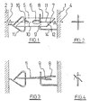
- Figura 1 shows a bolt of the first type.
- Two bodies schematically indicated under reference numerals 1 and 2 have the tendency to move apart under the influence of the forces 3 and 4. These forces are however detained by a bolt element in the form of a small plate 5 having an aperture 6 and a slit 7 connecting the aperture 6 with laws 8 and 9 with common basis 10.
- the plate 5 must not necessarily be rectangular, but can also e.g.
- Another hookable body 15 also in the form of a wire with circular section, but bent into a triangle in the plane of wire 14, is connected in a fixed way to body 2, and is hooked by the plate 5 because it passes through an additional aperture 16 in the plate, where it is also caught by the plate. It is remarked here that this wire 15 can also be made to pass through the opening 6 which comprises the slit, as shown fur the round plate on Figure 6, but an additional aperture 16, in the prolongation of the of slit 7, is preferred ( Figures 1 and 5) for the mechanical stability of the construction.
- the plate is made of a Cu-Zn-Al-alloy No. 1221, this means: 73.7 % Cu - 18.9 % Zn - 6.4 % AI - 0.024 % Ti and 0.39 % Co, which results in an As -temperature (starting temperature of the austenitic transformation) of about 68° C.
- This plate has been treated so as to have both jaws 8 and 9 in coplanar position (Figure 1) in a martensitic state (below the reaction temperature) and to make jaws 8 and 9 to bend upward, respectively downward out of the plane of the plate ( Figure 3) when the latter exceeds the reaction temperature.
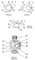
- FIG. 8 A second type of bolt, using a bolt element according to the invention, is shown in Figure 8.
- Two plates 41 and 42 forming part of a whole bolting system (not shown), are clamped in parallel, the one against the other, by means of a bolt element 43.
- These plates have the tendency to separate by sliding over each other's surface, under influence of a traction force T, a pression force F, or a flexion force D. They are however retained by a bolt element 43 that clamps both plates together.
- the correct positioning is guaranteed by the protrusions 44 in the contact surface of plate 41, which fit into the recesses or holes 45.
- This bolt element is shown in front view on Figure 10. It has the form of an oval plate having an aperture 49 connected via a slit with the external circumference of the plate, which need not be oval, but can have any appropriate other form, e.g. rectangular or circular. Both plates 41 and 42 are clamped in the slit 50.
- the bolt element must not necessarily be made completely of a shape memory alloy, although this embodiment is simple and cheap, It will be sufficient that only the part intended for the deformation be made of shape memory alloy, and this part must not necessarily be localized at the extremities of the jaws.
- the jaws produce both a deformation:. it is sufficient that the part where the jaws are in proximity to each other are moved apart from each other, i.e. that the distance becomes larger, and this can occur by a deformation of a single jaw.
Description
- The invention relates to a temperature responsive bolt element, and to temperature responsive bolts operating with such element. Especially in fire protection systems, there are applications where a conduit comprises a valve body which is pushed by a force in the opening or closing sense, but which is kept in open (in the case of a ventilation tube), respectively closed position (in the case uf an automatic sprinkler of a possible seat of a fire) because the valve body is retained by a bolt. The latter is however designed to give way as soon as the ambient temperature reaches an abnormal level, and the protection system then enters in action, under influence of the said force,
- In general, such a bolt connects two bodies (or two parts of a same deformable body) by means of a temperature-responsive bolt element which gives way when it reaches the critical temperature. The presently used bolt elements are e.g. heat-disintegratable bodies, e.g, by fusion or weakening, of which the mechanical resistance strongly falls down or disappears when the critical temperature is reached. In this sense, small sealed bulbs of fragile glass are used, filled with a liquid that evaporates at a critical temperature, so that the recipient is broken by the expansion of the liquid. Bolt systems, in which the unbolting movement is procured by a bimetallic strip are also known.
- The existing bolt elements can however difficultly reconcile all necessary or desirable requirements for such elements, the requirement of short response time, essential for fire protection systems, puts a serious limit to the dimension of the heat-sensitive body, and this puts a limit to the order of magnitude of the forces that the bolt is capable to withstand, and to the unbolting force that the element is capable to produce, and this is contrary to the requirement that these forces should be as high as possible.
- The use of bimetallic strips presents the difficulty of a rather large necessary strip volume to produce sufficient unbolting force, hence a high response time and such a strip works progressively without having a sharply defined reaction temperature. Fuse alloys show a better defined reaction temperature but, as they stand under normal conditions rather near to the weakening point, the forces acting on the bolt cause the body to flow slowly. Evaporation glass bulbs have a sharply defined reaction temperature, but the response time is high, due to the liquid that must be heated, and they are fragile.
- It is the object of the present invention to procure a temperature-responsive bolt element that reconciles much better the above requirements, which can be manufactured in a simple way, and which can serve again after an unbolting action.
- According to the invention, the bolt element comprises a pair of coplanar flat jaws opposite to each other and having a common basis, the resistance moment to flexion in the plane of each jaw being at least tenfold the resistance moment to flexion in a plane perpendicular to the plane of the jaw, and further comprises a shape memory alloy, treated for moving said jaws apart from each other in a direction substantially perpendicular to the plane of the jaws, when the alloy exceeds its reaction temperature.
- As the jaws start from a common basis at one side, and at the other side are opposite to each other, i.e. turned towards each other, leaving a narrow opening or slit between them, they will have a hook shape. But this must not necessarily be such that the jaws then, such as hooks, can catch any other shape.
- When this is however the case, the bolt element can serve in a first preferred type of bolt, where it catches another hookable body. In a second preferred type of bolt, it clamps two bedies between the laws, as will be explained below.
- The mentioned characteristics of the bolt element enable this element to be used in a way that the forces that the bolt has to withstand act against the high flexion resistance of the jaws in their own plane, whereas the unbolting force that the element has to produce occurs in the low flexion resistance plane, perpendicular to the plane of the jaws. In this way, the proportion of the force to withstand, to the unbolting force to produce (i.e. the necessary volume of the body or the minimum necessary response time) can be brought to a maximum. In the first type of bolt for instance, a traction force of 150 N can be retained by a piece of 3 gram.
- The abovementioned preferred first type of bolt, serving to connect two body parts (i.e. two parts of different bodies or of a same deformable body) in an unboltable way will be characterized in that it comprises a temperature responsive bolt element according to the invention, and a hookable body (i.e. hookable by the jaws of the bolt element), fixed to the first body part and caught by the jaws in a position in a plane perpendicular to the plane of the jaws, the bolt element being pivotably fixed to the second body part, the pivoting axis being the intersecting line between both planes.
- The abovementioned preferred second type of bolt, serving to connect two body parts in an unboltable way will in its turn be characterized in that it also comprises a temperature responsive bolt element according to the invention, both body parts comprising each a plate, both plates being clamped against each other between the jaws of said bolt element.
- The invention will be explained hereunder with reference to a number of drawings, given only by way of example, and in which:
- Figure 1 shows a perspective view of a first preferred type of bolt using a bolting element according to the invention, and in normal position;
- Figure 2 shows a front view of the same bolt, still in normal position;
- Figure 3 shows a perspective view of the same bolt, in a pivoted position where the bolt element begins to release;
- Figure 4 shows a front view of the bolt, in pivoted position;
- Figures 5 and 6 show other embodiments of the bolt element according to the invention;
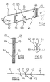
- Figure 7 shows such first type of bolt, applied to a fire extinguishing sprinkler;
- Figure 8 shows a perspective view of a second preferred type of bolt, using a bolt element according to the invention, and in normal bolting position;
- Figure 9 shows a detailed cross-sectional side view of a part of such second type of bolt;,
- Figure 10 shows a side view of the bolt, in which the bolt element can be seen in front view;
- Figure 11 shows a cross-sectional view of the same bolt, taken in a plane perpendicular to the intersection line of the plane of the bolted plates with the plane of the bolt element;
- Figure 12 shows a schematic view of the essential parts of the bolt element.
- Shape memory alloys are well known. These are alloys having a martensitic phase at lower temperatures and an austenitic phase at higher temperature (the transformation between both starting at a given temperature, called hereinafter the"reaction temperature"), and being appropriated to produce the shape memory effect. This effect was discovered in the 1950's with certain Cu-Zn, Au-Cd and Ni-fi alloys, and other such alloys were found later on among the ternary and quaternary alloys of Fe, Ni, Cr, Co or Mn, and which are well-known. In particular, the ternary Cu-AI-Zn alloys with shape memory effect are well known, of which the composition is represented in a ternary diagram inside a trapezium having the following corner points (expressed in percentages by weight of Cu, AI and Zn respectively: A (64; 1; 35), B (74; 5; 21), C (87,5; 12,5; O) and D (86; 14; 0).
- In order to obtain a desired shape memory effect, the alloy must be treated accordingly, as well known. For these alloys it was discovered indeed that, when the alloy has been deformed, in the"cold" or martensitic state, from an initial shape towards a second shape, and when the alloy is then heated up into its austenitic phase, it takes the initial shape again. This means that the alloy, after deformation, has memorized its initial shape. When it comes back to its cold state, the alloy takes again, more or less perfectly, said second shape. The alloy can then be deformed again in the exact second shape, and the alloy, when then heated up towards the austenitic state, will change shape towards the initial shape again. When cooling down again, the return towards said second shape will be the more perfect, according as the alloy will have undergone more cycles of heating up - cooling down-deformation to second shape, as described hereabove, this constituting the treatment of the alloy.
- Figura 1 shows a bolt of the first type. Two bodies, schematically indicated under
reference numerals 1 and 2, have the tendency to move apart under the influence of theforces small plate 5 having anaperture 6 and aslit 7 connecting theaperture 6 withlaws common basis 10. Theplate 5 must not necessarily be rectangular, but can also e.g. have an oval (Figure 5) or circular (Figure 6) shape, in so far as one can distinguish, as in the case of Figures 1, 5 and 6, in the state at normal room temperature, twocoplanar jaws 8 and which have acommon basis 10 at one side and which are turned towards each other at the other side, leaving a narrow opening or slit 7 between them, Theextremities slit 7. - A
hookable body 14, in the form of a wire with circular cross-section and bent over a right angle, is connected in a fixed way to body 1, and it enters intoopening 6, where it is caught by theplate 5 between the twoextremities jaws slit 7. - Another
hookable body 15, also in the form of a wire with circular section, but bent into a triangle in the plane ofwire 14, is connected in a fixed way tobody 2, and is hooked by theplate 5 because it passes through anadditional aperture 16 in the plate, where it is also caught by the plate. It is remarked here that thiswire 15 can also be made to pass through theopening 6 which comprises the slit, as shown fur the round plate on Figure 6, but anadditional aperture 16, in the prolongation of the ofslit 7, is preferred (Figures 1 and 5) for the mechanical stability of the construction. - In this system one can observe that the plate is connected to
body 2 in a pivotable way around pivot line AA (Figure 1). As the whole system is however under tension, theplate 5 will direct itself into a plane perpendicular to the plane ofwires hook 14. This is shown in front view on Figure 2. The plate in this example has a thickness of 0.5 mm and a surface of about 1 cm2, and serves to resist to a tensile force of 50 Newton. Depending on the desired resistance, the thickness will in general range between 0.2 mm and 1 mm, and the surface between 0.5 cm2 and 20 cm2. - The plate is made of a Cu-Zn-Al-alloy No. 1221, this means: 73.7 % Cu - 18.9 % Zn - 6.4 % AI - 0.024 % Ti and 0.39 % Co, which results in an As -temperature (starting temperature of the austenitic transformation) of about 68° C. This plate has been treated so as to have both
jaws jaws plate 5 to begin to pivot around axis AA (Figure 3 and front view of Figure 4), because of the low bending resistance now and it will release thewire 14. The body 1 is then unbolted frombody 2. After cooling-down, the plate comes back towards its coplanar form, and thewire 14 can then be entered again in theaperture 6 to bolt the system again. - A particularly practical application of such bolt is shown in Figure 7, for an automatic fire extinguishing sprinkler. Such a system comprises a threaded
tube end 30 for screwing the same into a water pipe under pressure. - The outlet of this tube end is obturated by a water-
tight cover 31, the water pressure tending to push the cover downward. Thecover 31 is however retained by twolevers first lever 32 leans, in a pivotable way, on one hand againstcover 31, and on the other hand with its fulcrum against asimilar fulcrum 34 of theother lever 33, and comprises anarm 35. Theother lever 33 is similar to the first one, and leans, in a pivotable way, on one hand against acrown 37, fixed at the end oftube 30, and on the other hand againstfulcrum 34 oflever 32, and also comprises anarm 36. One can see that thearms cover 31 downward. Thesearms bolt element 38 of the type described, so that the cover stays in its place as drawn in the figure. In this case, thearm 35 is the hookable body that is caught by the jaws of thebolt element 38. - At the start of a fire in the proximity of this sprinkler, which produces a temperature raise of the surrounding atmosphere, the
element 38 will give way as explained above, and this will result in a water jet, directed towardscrown 39 which will distribute the water in all directions. - A second type of bolt, using a bolt element according to the invention, is shown in Figure 8. Two
plates bolt element 43. These plates have the tendency to separate by sliding over each other's surface, under influence of a traction force T, a pression force F, or a flexion force D. They are however retained by abolt element 43 that clamps both plates together. The correct positioning is guaranteed by theprotrusions 44 in the contact surface ofplate 41, which fit into the recesses or holes 45. - This is shown more in detail on Figure 9. In such a way both
plates jaws 47 and 48 (Figure 10) of thebolt element 43. - This bolt element is shown in front view on Figure 10. It has the form of an oval plate having an
aperture 49 connected via a slit with the external circumference of the plate, which need not be oval, but can have any appropriate other form, e.g. rectangular or circular. Bothplates slit 50. - The
plate 43 is made of the same alloy and treated in the same way as described above to makejaws plate 43 when the latter exceeds the reaction temperature. This will result in theplate 43 to begin to pivot (Figure 11 in dotted line) and to be no longer capable of clamping theplates plate 41 is unbolted fromplate 42 and, under influence of the forces T, F or D (Figure 8), will be able to overcome the last obstacle to sliding apart: the fitting of theprotrusions 44 into therecesses 45 in the contact surfaces between bothplates 41ad 42. After opening of the bolt and cooling-down, theplate 43 comes back towards its coplanar form, and bothplates - The embodiments of the second type of bolt are not limited to the example above. The two
plates protrusion 44 fitting with onerecess 45, or several such pairs of protrusion and recess, when the sliding is to be initiated under a bending force D. - One plate must not necessarily contain all the protrusions and the other one all the recesses. Nor is it necessary that the
plates jaws - For such bolt systems, several bolt element configurations can be designed, based on the same principle and without departing from the idea of the invention, schematically shown in Figure 12: two
coplanar jaws common basis 10, and which are at the other side turned towards each other and "near" to each other. This distance between the jaws in normal position at ambient temperature, wlil depend e.g. in the case of Figure 1 on the thickness of thewire 14 which is to be retained by thejaws extremities plate 5 of Figure 1 for instance, the smallest dimension of theextremities slit 7 will consequently have a width, preferably ranging from zero to maximum five times this thickness, but can be larger in certain specific cases. It is however necessary that thejaws - This is the reason why these
jaws - The bolt elements according to the invention are temperature sensitive, but the temperature must not necessarily be procured by a temperature raise of the surrounding atmosphere. A remote control of these elements is possible by mounting (e.g. by means of solder) an electric resistance in close heat conducting contact with the shape-memory alloy of the element, the resistance being connected to a voltage supply over a control system which connects the resistance with said supply when the bolt has to enter in action for unbolting. By producing sufficient heat dissipation in the resistor, the shape memory alloy will then exceed its reaction temperature. By using a resistor with positive temperature coefficient (a PTC-thermistor), a short heating time can be obtained without leading to overheating of the alloy, because a PTC-thermistor, as well known, as the temperature rises, produces less heat, so stabilizing the temperature.
- The bolt element must not necessarily be made completely of a shape memory alloy, although this embodiment is simple and cheap, It will be sufficient that only the part intended for the deformation be made of shape memory alloy, and this part must not necessarily be localized at the extremities of the jaws. One can for instance design an element (see Figure 12), where the
jaws basis 10 is treated in order to produce a light twist around axis BB when the reaction temperature is reached:. the jaws will then atextremities jaws - The exact composition of the shape memory alloy will depend on the desired reaction temperature- For Cu-AI-Zn alloys for instance, it is known that the reaction temperature can be increased by lowering the zinc content and increasing the copper content accordingly, or by lowering the aluminium content and increasing the copper or zinc content accordingly. Two parameters can consequently be varied in order to obtain the desired reaction temperature, as well known. For instance: in order to obtain a lower reaction temperature than for the abovementioned No.1221 alloy (As = 68°C), the alloy No. 1168 can be used: 74.4% Cu - 17% Zn - 7.55% A1 (As = 65°C). For safety applications against overheating conditions, this reaction temperature shall range between 30°C and 150°C. For fire protection systems, this value shall preferably be chosen between 55° C and 85° C.
- The alloy and its treatment can also be such, that the unbolting occurs, not when the temperature exceeds a limit (e.g. 70°C) in the upward sense, but also when it exceeds or crosses a limit value (e.g. -50°C) in the downward sense. The invention is consequently not limited to temperature responsive elements with a reaction temperature above ambient room temperature, but also below. For a butane or propane supply valve towards a tank for instance, when the liquid in the tank reaches a level at which the supply flow must be stopped, a small quantity of the liquid is made to escape in a way that its evaporation and rapid expansion transforms it into a cold gas jet directed to such temperature sensitive bolt which unbolts the supply valve so that the latter can close under influence of a spring or other pression.
- With respect to the reaction temperature of the alloy: the latter starts, respectively finishes its transformation towards austenite at a temperature AS, respectively Af, and the return towards the martensite phase in the opposite sense starts, respectively finishes at a temperature Ms and Mf respectively. As well known, these four temperatures lie sometimes in a rather broad range of 20° to 50° difference. For the alloys however where the reaction occurs above normal ambient temperatures (40° C and more), respectively below (-30°C and lower), it is clear that the system will respond at the temperature Ag respectively MS. These temperatures are consequently to be considered respectively as the"reaction temperatures" of the alloy.
- The invention is not limited to the examples given hereinabove. Other embodiments and equivalents can be designed without departing from the scope of the invention as defined by the claim. In particular, the wording such as "coplanar" and "perpendicular" are not to be considered in this strict geometrical and abstract sense, but more in the sense of about coplanar or perpendicular.
Claims (11)
Priority Applications (1)
| Application Number | Priority Date | Filing Date | Title |
|---|---|---|---|
| AT84200962T ATE24279T1 (en) | 1983-07-11 | 1984-07-04 | LOCKING ELEMENT. |
Applications Claiming Priority (4)
| Application Number | Priority Date | Filing Date | Title |
|---|---|---|---|
| LU84905 | 1983-07-11 | ||
| LU84905A LU84905A1 (en) | 1983-07-11 | 1983-07-11 | LOCKING ELEMENT AND THERMOSENSITIVE LOCK |
| LU85260A LU85260A1 (en) | 1984-03-21 | 1984-03-21 | Temp. responsive bolt for automatic fire extinguisher - having jaws separated in perpendicular direction by shape memory alloy |
| LU85260 | 1984-03-21 |
Publications (2)
| Publication Number | Publication Date |
|---|---|
| EP0131997A1 EP0131997A1 (en) | 1985-01-23 |
| EP0131997B1 true EP0131997B1 (en) | 1986-12-17 |
Family
ID=26640301
Family Applications (1)
| Application Number | Title | Priority Date | Filing Date |
|---|---|---|---|
| EP84200962A Expired EP0131997B1 (en) | 1983-07-11 | 1984-07-04 | Temperature responsive bolt element |
Country Status (3)
| Country | Link |
|---|---|
| US (1) | US4596483A (en) |
| EP (1) | EP0131997B1 (en) |
| DE (1) | DE3461685D1 (en) |
Families Citing this family (42)
| Publication number | Priority date | Publication date | Assignee | Title |
|---|---|---|---|---|
| US4699314A (en) * | 1986-12-17 | 1987-10-13 | Carrier Corporation | Actuator for a heating/cooling diffuser |
| GB8723226D0 (en) * | 1987-10-02 | 1987-11-04 | Bolton & Johnson Ltd Thomas | Fire sprinklers |
| US4842106A (en) * | 1987-10-08 | 1989-06-27 | Hughes Aircraft Company | Rate controllable damping mechanism |
| US4905765A (en) * | 1988-08-22 | 1990-03-06 | Hein George P | Smoke detector/remote controlled shape-memory alloy fire extinguisher discharge apparatus |
| US4887430A (en) * | 1988-12-21 | 1989-12-19 | Eaton Corporation | Bistable SME actuator with retainer |
| US5024549A (en) * | 1989-06-28 | 1991-06-18 | Mrj Group, Inc. | Method and apparatus for joining structural members |
| EP0456950A1 (en) * | 1990-05-16 | 1991-11-21 | CONTRAVES ITALIANA S.p.A. | Actuator for restraint/release (R/R) devices, particularly for space applications |
| US5540689A (en) * | 1990-05-22 | 1996-07-30 | Sanders; Albert E. | Apparatus for securing a rod adjacent to a bone |
| US5192147A (en) * | 1991-09-03 | 1993-03-09 | Lockheed Missiles & Space Company, Inc. | Non-pyrotechnic release system |
| FI90394C (en) * | 1992-04-23 | 1994-02-10 | Goeran Sundholm | The fire-fighting unit |
| US5494113A (en) * | 1994-02-01 | 1996-02-27 | Central Sprinkler Corporation | Sprinklers with shape-memory alloy actuators |
| US5686878A (en) * | 1995-04-03 | 1997-11-11 | Gueli; Carmen | Temperature sensitive fusible link assembly having cooperating projections and slots |
| GB2320277B (en) * | 1996-12-09 | 2001-10-10 | Univ Brunel | Improvements relating to product disassembly |
| GB9818052D0 (en) * | 1998-08-20 | 1998-10-14 | British Aerospace | Fastening arrangements |
| US20030170092A1 (en) * | 1999-12-22 | 2003-09-11 | Chiodo Joseph David | Releasable fasteners |
| FR2825766B1 (en) * | 2001-06-08 | 2003-10-10 | Lacroix Soc E | THERMAL EFFECT CONTROLLED RELEASE MECHANISM |
| KR20040022268A (en) * | 2002-09-03 | 2004-03-12 | 마임인터내셔날코포레이션 주식회사 | Sprinkler |
| JP4328229B2 (en) * | 2003-06-04 | 2009-09-09 | 株式会社ユニオン精密 | Fastening structure using screw accessories and disassembly method using screw accessories |
| US7586828B1 (en) | 2003-10-23 | 2009-09-08 | Tini Alloy Company | Magnetic data storage system |
| US7422403B1 (en) | 2003-10-23 | 2008-09-09 | Tini Alloy Company | Non-explosive releasable coupling device |
| US7632361B2 (en) * | 2004-05-06 | 2009-12-15 | Tini Alloy Company | Single crystal shape memory alloy devices and methods |
| US20060118210A1 (en) * | 2004-10-04 | 2006-06-08 | Johnson A D | Portable energy storage devices and methods |
| US7763342B2 (en) * | 2005-03-31 | 2010-07-27 | Tini Alloy Company | Tear-resistant thin film methods of fabrication |
| US7441888B1 (en) | 2005-05-09 | 2008-10-28 | Tini Alloy Company | Eyeglass frame |
| US7540899B1 (en) | 2005-05-25 | 2009-06-02 | Tini Alloy Company | Shape memory alloy thin film, method of fabrication, and articles of manufacture |
| US8720722B2 (en) * | 2005-12-15 | 2014-05-13 | Cornerstone Research Group, Inc. | Venting mechanism for containers |
| US20070246233A1 (en) * | 2006-04-04 | 2007-10-25 | Johnson A D | Thermal actuator for fire protection sprinkler head |
| US20080075557A1 (en) * | 2006-09-22 | 2008-03-27 | Johnson A David | Constant load bolt |
| US20080213062A1 (en) * | 2006-09-22 | 2008-09-04 | Tini Alloy Company | Constant load fastener |
| US8349099B1 (en) | 2006-12-01 | 2013-01-08 | Ormco Corporation | Method of alloying reactive components |
| US8584767B2 (en) * | 2007-01-25 | 2013-11-19 | Tini Alloy Company | Sprinkler valve with active actuation |
| US8684101B2 (en) * | 2007-01-25 | 2014-04-01 | Tini Alloy Company | Frangible shape memory alloy fire sprinkler valve actuator |
| DE102007028503B3 (en) * | 2007-06-18 | 2008-09-18 | Thomas Magnete Gmbh | Device for holding safety system set under prestress, has hook element, which is formed elongated and is arranged with its longitudinal axis parallel to safety system |
| US8007674B2 (en) | 2007-07-30 | 2011-08-30 | Tini Alloy Company | Method and devices for preventing restenosis in cardiovascular stents |
| WO2009073609A1 (en) | 2007-11-30 | 2009-06-11 | Tini Alloy Company | Biocompatible copper-based single-crystal shape memory alloys |
| US7842143B2 (en) * | 2007-12-03 | 2010-11-30 | Tini Alloy Company | Hyperelastic shape setting devices and fabrication methods |
| US8382917B2 (en) | 2007-12-03 | 2013-02-26 | Ormco Corporation | Hyperelastic shape setting devices and fabrication methods |
| US8899342B2 (en) * | 2008-07-31 | 2014-12-02 | Lyle H Chesley | Safety apparatus |
| US10124197B2 (en) | 2012-08-31 | 2018-11-13 | TiNi Allot Company | Fire sprinkler valve actuator |
| US11040230B2 (en) | 2012-08-31 | 2021-06-22 | Tini Alloy Company | Fire sprinkler valve actuator |
| WO2019183408A1 (en) * | 2018-03-22 | 2019-09-26 | Johnson Controls Technology Company | Smart material mechanism for fire sprinklers |
| US20200289861A1 (en) * | 2019-03-15 | 2020-09-17 | Richard E. Venturini | Fire rated pet door assembly and activation system |
Family Cites Families (8)
| Publication number | Priority date | Publication date | Assignee | Title |
|---|---|---|---|---|
| US2396906A (en) * | 1945-02-06 | 1946-03-19 | Antoine E Windson | Balloon sealing device |
| US3561537A (en) * | 1968-06-20 | 1971-02-09 | Fire Protection Co | Automatic sprinkler head |
| US3740839A (en) * | 1971-06-29 | 1973-06-26 | Raychem Corp | Cryogenic connection method and means |
| US3783429A (en) * | 1972-06-21 | 1974-01-01 | Raychem Corp | Temperature actuated connector |
| FR2254184A5 (en) * | 1973-11-07 | 1975-07-04 | Vindry Georges | Sprinkler for automatic fire fighting - bimetallic strip releases trigger to release plug over delivery conduit |
| US4068820A (en) * | 1974-08-26 | 1978-01-17 | Texas Instruments Incorporated | Valve |
| JPS588817A (en) * | 1981-07-03 | 1983-01-19 | 株式会社山科精工所 | Elastic washer |
| US4414716A (en) * | 1981-10-05 | 1983-11-15 | Frank Stastney | Garment clasping device |
-
1984
- 1984-07-04 DE DE8484200962T patent/DE3461685D1/en not_active Expired
- 1984-07-04 EP EP84200962A patent/EP0131997B1/en not_active Expired
- 1984-07-10 US US06/629,416 patent/US4596483A/en not_active Expired - Fee Related
Also Published As
| Publication number | Publication date |
|---|---|
| US4596483A (en) | 1986-06-24 |
| EP0131997A1 (en) | 1985-01-23 |
| DE3461685D1 (en) | 1987-01-29 |
Similar Documents
| Publication | Publication Date | Title |
|---|---|---|
| EP0131997B1 (en) | Temperature responsive bolt element | |
| US5494113A (en) | Sprinklers with shape-memory alloy actuators | |
| US3561537A (en) | Automatic sprinkler head | |
| US3974844A (en) | Valve | |
| US5071064A (en) | Shape memory actuator smart connector | |
| US5176544A (en) | Shape memory actuator smart connector | |
| US5788212A (en) | Pressure relief device with shaped memory alloy thermally activated trigger | |
| US4757865A (en) | Fast response sprinkler head | |
| US10203042B2 (en) | Self-contained actuated safety valve for gaseous or liquid fuel lines and the like | |
| US3911940A (en) | Delayed closing fire sprinkler heads | |
| US4068820A (en) | Valve | |
| US4763711A (en) | Fire damper | |
| US4283006A (en) | Thermally-activated closure device | |
| GB2209200A (en) | Thermal cut-off valve | |
| US4298068A (en) | Heat sensitive release devices | |
| US6338624B1 (en) | Automatic putting-out apparatus | |
| US3845931A (en) | Valve | |
| RU2195986C1 (en) | Thermal lock for sprinkler-type sprayer | |
| US4805261A (en) | Resettable fire link | |
| JPS6075067A (en) | Thermal responsive coupling apparatus | |
| US1177182A (en) | Automatic sprinkler. | |
| JPS6364612B2 (en) | ||
| US3742417A (en) | Thermal tripping devices for safety installations and the like | |
| JPS5725573A (en) | Expansion valve with shape memory alloy | |
| US608677A (en) | Sprinkler-head for automatic |
Legal Events
| Date | Code | Title | Description |
|---|---|---|---|
| PUAI | Public reference made under article 153(3) epc to a published international application that has entered the european phase |
Free format text: ORIGINAL CODE: 0009012 |
|
| AK | Designated contracting states |
Designated state(s): AT BE CH DE FR GB IT LI NL SE |
|
| 17P | Request for examination filed |
Effective date: 19850327 |
|
| 17Q | First examination report despatched |
Effective date: 19860313 |
|
| GRAA | (expected) grant |
Free format text: ORIGINAL CODE: 0009210 |
|
| AK | Designated contracting states |
Kind code of ref document: B1 Designated state(s): AT BE CH DE FR GB IT LI NL SE |
|
| REF | Corresponds to: |
Ref document number: 24279 Country of ref document: AT Date of ref document: 19870115 Kind code of ref document: T |
|
| ITF | It: translation for a ep patent filed |
Owner name: SOCIETA' ITALIANA BREVETTI S.P.A. |
|
| REF | Corresponds to: |
Ref document number: 3461685 Country of ref document: DE Date of ref document: 19870129 |
|
| ET | Fr: translation filed | ||
| PLBE | No opposition filed within time limit |
Free format text: ORIGINAL CODE: 0009261 |
|
| STAA | Information on the status of an ep patent application or granted ep patent |
Free format text: STATUS: NO OPPOSITION FILED WITHIN TIME LIMIT |
|
| 26N | No opposition filed | ||
| PGFP | Annual fee paid to national office [announced via postgrant information from national office to epo] |
Ref country code: SE Payment date: 19900620 Year of fee payment: 7 |
|
| PGFP | Annual fee paid to national office [announced via postgrant information from national office to epo] |
Ref country code: GB Payment date: 19900622 Year of fee payment: 7 |
|
| PGFP | Annual fee paid to national office [announced via postgrant information from national office to epo] |
Ref country code: AT Payment date: 19900706 Year of fee payment: 7 |
|
| PGFP | Annual fee paid to national office [announced via postgrant information from national office to epo] |
Ref country code: CH Payment date: 19900726 Year of fee payment: 7 |
|
| ITTA | It: last paid annual fee | ||
| PGFP | Annual fee paid to national office [announced via postgrant information from national office to epo] |
Ref country code: NL Payment date: 19900731 Year of fee payment: 7 |
|
| PGFP | Annual fee paid to national office [announced via postgrant information from national office to epo] |
Ref country code: DE Payment date: 19900827 Year of fee payment: 7 |
|
| PGFP | Annual fee paid to national office [announced via postgrant information from national office to epo] |
Ref country code: FR Payment date: 19910618 Year of fee payment: 8 |
|
| PGFP | Annual fee paid to national office [announced via postgrant information from national office to epo] |
Ref country code: BE Payment date: 19910619 Year of fee payment: 8 |
|
| PG25 | Lapsed in a contracting state [announced via postgrant information from national office to epo] |
Ref country code: GB Effective date: 19910704 Ref country code: AT Effective date: 19910704 |
|
| PG25 | Lapsed in a contracting state [announced via postgrant information from national office to epo] |
Ref country code: SE Effective date: 19910705 |
|
| PG25 | Lapsed in a contracting state [announced via postgrant information from national office to epo] |
Ref country code: LI Effective date: 19910731 Ref country code: CH Effective date: 19910731 |
|
| PG25 | Lapsed in a contracting state [announced via postgrant information from national office to epo] |
Ref country code: NL Effective date: 19920201 |
|
| GBPC | Gb: european patent ceased through non-payment of renewal fee | ||
| NLV4 | Nl: lapsed or anulled due to non-payment of the annual fee | ||
| REG | Reference to a national code |
Ref country code: CH Ref legal event code: PL |
|
| PG25 | Lapsed in a contracting state [announced via postgrant information from national office to epo] |
Ref country code: DE Effective date: 19920401 |
|
| PG25 | Lapsed in a contracting state [announced via postgrant information from national office to epo] |
Ref country code: BE Effective date: 19920731 |
|
| BERE | Be: lapsed |
Owner name: LEUVEN RESEARCH & DEVELOPMENT Effective date: 19920731 |
|
| PG25 | Lapsed in a contracting state [announced via postgrant information from national office to epo] |
Ref country code: FR Effective date: 19930331 |
|
| REG | Reference to a national code |
Ref country code: FR Ref legal event code: ST |
|
| EUG | Se: european patent has lapsed |
Ref document number: 84200962.3 Effective date: 19920210 |