EP0133269A2 - Locking mechanism for an office panel system - Google Patents
Locking mechanism for an office panel system Download PDFInfo
- Publication number
- EP0133269A2 EP0133269A2 EP84108692A EP84108692A EP0133269A2 EP 0133269 A2 EP0133269 A2 EP 0133269A2 EP 84108692 A EP84108692 A EP 84108692A EP 84108692 A EP84108692 A EP 84108692A EP 0133269 A2 EP0133269 A2 EP 0133269A2
- Authority
- EP
- European Patent Office
- Prior art keywords
- panels
- locking
- tubular member
- locking mechanism
- members
- Prior art date
- Legal status (The legal status is an assumption and is not a legal conclusion. Google has not performed a legal analysis and makes no representation as to the accuracy of the status listed.)
- Withdrawn
Links
- 238000000465 moulding Methods 0.000 claims description 12
- 239000004744 fabric Substances 0.000 claims description 6
- 239000011324 bead Substances 0.000 claims description 3
- 230000000295 complement effect Effects 0.000 claims description 3
- 239000000463 material Substances 0.000 description 5
- 238000005192 partition Methods 0.000 description 5
- 239000006261 foam material Substances 0.000 description 2
- 230000006978 adaptation Effects 0.000 description 1
- 230000008878 coupling Effects 0.000 description 1
- 238000010168 coupling process Methods 0.000 description 1
- 238000005859 coupling reaction Methods 0.000 description 1
- 230000001419 dependent effect Effects 0.000 description 1
- 238000009408 flooring Methods 0.000 description 1
- 238000004519 manufacturing process Methods 0.000 description 1
- 230000004048 modification Effects 0.000 description 1
- 238000012986 modification Methods 0.000 description 1
- 239000012858 resilient material Substances 0.000 description 1
Images

Classifications
-
- E—FIXED CONSTRUCTIONS
- E04—BUILDING
- E04B—GENERAL BUILDING CONSTRUCTIONS; WALLS, e.g. PARTITIONS; ROOFS; FLOORS; CEILINGS; INSULATION OR OTHER PROTECTION OF BUILDINGS
- E04B2/00—Walls, e.g. partitions, for buildings; Wall construction with regard to insulation; Connections specially adapted to walls
- E04B2/74—Removable non-load-bearing partitions; Partitions with a free upper edge
- E04B2/7407—Removable non-load-bearing partitions; Partitions with a free upper edge assembled using frames with infill panels or coverings only; made-up of panels and a support structure incorporating posts
- E04B2/7416—Removable non-load-bearing partitions; Partitions with a free upper edge assembled using frames with infill panels or coverings only; made-up of panels and a support structure incorporating posts with free upper edge, e.g. for use as office space dividers
- E04B2/7422—Removable non-load-bearing partitions; Partitions with a free upper edge assembled using frames with infill panels or coverings only; made-up of panels and a support structure incorporating posts with free upper edge, e.g. for use as office space dividers with separate framed panels without intermediary support posts
- E04B2/7425—Details of connection of panels
-
- Y—GENERAL TAGGING OF NEW TECHNOLOGICAL DEVELOPMENTS; GENERAL TAGGING OF CROSS-SECTIONAL TECHNOLOGIES SPANNING OVER SEVERAL SECTIONS OF THE IPC; TECHNICAL SUBJECTS COVERED BY FORMER USPC CROSS-REFERENCE ART COLLECTIONS [XRACs] AND DIGESTS
- Y10—TECHNICAL SUBJECTS COVERED BY FORMER USPC
- Y10S—TECHNICAL SUBJECTS COVERED BY FORMER USPC CROSS-REFERENCE ART COLLECTIONS [XRACs] AND DIGESTS
- Y10S52/00—Static structures, e.g. buildings
- Y10S52/13—Hook and loop type fastener
Abstract
A locking mechanism for joining first and second panels along facing sides, including a tubular member extending along the facing sides of the panels. A recess formed in each of the facing sides of the panels and with each recess of a depth to receive approximately half the width of the tubular member to have the tubular member substantially enclosed by the facing recesses. At least one locking member extending within each recess and with the locking members each having an enlarged head positioned within the recess. The tubular member including locking openings corresponding in number and position to the locking members and with the locking openings formed with an enlarged portion to receive the enlarged head of the locking member to have the enlarged head positioned within the interior of the tubular member. The locking openings formed with an elongated portion extending from the enlarged portion and with the width of the elongated portion smaller than the size of the enlarged head and with the tubular member moved axially to position the locking members within the elongated portions of the locking openings to have the enlarged heads captured within the tubular member to lock each of the panels to the tubular member.
Description
- The present invention relates to a locking mechanism for an office panel system and in particular is directed to a locking mechanism for joining.together panels to form partitions which may define work areas and wherein such locking mechanism may receive and support mounting brackets which brackets can support shelves or other furniture structures.
- Office panel systems have been designed so as to separate a large office space into a plurality of defined work areas. In addition, the panels themselves may be used to support shelves, desks, etc. without the necessity of providing separate pieces of furnitures. These office panel systems are extremely versatile and allow for any given office space to be custom designed to meet the specific needs of a plurality of different workers, each with a defined work area.
- In addition, the office panel systems are efficient in their use of space since each work area may encompass a desk or other working space, and with shelf space either above or below the working space or both and with the arrangement of each work area provided by joining the panels together in a desired spatial arrangement. The particular types of arrangements are only limited by the types of joints that are practical for joining the various panel members. These joints may provide for a series of panels arranged along a straight line and may also provide for right angle joints, T-joints and intersecting panels. In addition, angular relationships other than ninety degrees (90°) may be provided between the panels.
- The panels serve as a wall or partition member to define the separate work areas and these panels may have various heights and widths dependent upon the particular use for the panels. The panels should be easily locked to each other so as to be able to quickly assemble the partitions and associated furniture to define the arrangement of the work areas. In addition, the panels should be easily unlocked from each other so that the arrangement may be changed or moved.
- The prior art office panel systems have a number of difficulties and in particular are often difficult to both assemble and disassemble. Also with the prior art systems it is often difficult to align the panels precisely when assembled. In addition, the prior art devices often include the use of separate members which must be attached after the panels are assembled so as to hide the locking structure.
- The present invention is directed to a novel locking mechanism for office panel systems for coupling together two (2) or more panels forming partitions so as to define work areas. Each panel includes a recess so as to receive a tubular member. Each panel also includes locking members extending within the recess and with the locking means having enlarged head portions. The tubular members includes complementary teardrop shaped openings so as to receive the enlarged head of the locking members. The upper end of the tubular member includes a nut portion so as to receive a bolt and with the bolt passing through an opening at an upper end of the panel.
- In operation, the tubular member is positioned within oppositely facing recesses in adjacent panels and with the enlarged head portions of the locking members passing through the enlarged portions of the teardrop shape openings in the tubular member. The bolt member is then passed through openings at the upper end of the panels to be received within the integral nut portion at the top of the tubular member. When the bolt member is tightened, the tubular member is drawn upward so that the enlarged heads of the locking members are moved within the elongated portions of the teardrop shape openings. The tubular member is then pulled tightly into and locked within the recesses in the panel members so as to firmly attach and align the panel members together. The attachment structure is hidden within the recesses and the only visible element would be the top of the bolt which may actually be received within recess portions of the panel members.
- The invention also includes other structural advantages such as hinged bottom covers with unique fasteners so as to expose a bottom portion of the panel for various types of wiring. In addition, the adjacent edges of the panel may include resilient molding members so that the resilient molding members may be compressed to allow for shelf support members to be received and supported by the tubular members.
- A clearer understanding of the invention will be had with reference to the following descriptions and drawings wherein:
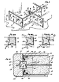
- Figure 1 illustrates a perspective view of an office panel system of the present invention arranged to provide a plurality of work areas;
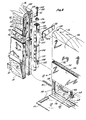
- Figure 2 is an exploded perspective detailed view of the locking mechanism of the present invention used to join adjacent panels;
- Figure 3 is a detailed cross-sectional view illustrating the locking mechanism when initially engaging the panel members;
- Figure 4 is a detailed cross-sectional view illustrating the locking mechanism engaged to join together the panel members;
- Figure 5 is a top cross-sectional view taken along lines 5-5 of Figure 4 illustrating the locking member joining panel members;
- Figure 6 is a top cross-sectional view taken along lines 6-6 of Figure 1 illustrating an end joint member locked to a panel member with the locking mechanism;
- Figure 6a is a top cross-sectional view of a right angle joint member for the office panel system.
- Figure 6b is a top cross-sectional view of a T-joint member for the office panel system; and
- Figure 6c is a top cross-sectional view of a cross joint member for joining intersecting panels.
- As shown in Figure 1 an office panel system 10 is composed of a plurality of
separate panel members 12. The panel members may have various widths but in general, for each particular office system, the panel members would be of the same height. However, if desired, panel members of different heights may be used. - Each
panel member 12 in general includes abottom portion 14, whichbottom portion 14 may be used to house various wiring to provide for electrical outlets, telephone outlets etc. In addition, eachpanel member 12 includes atop cover portion 16. In the particular embodiment shown, thecover portions 16 are shown to be separate attached elements but the cover portions may be formed integrally with thepanels 12. With the present invention, thecover portions 16 may be permanently attached or integrally formed since it is not necessary to remove the cover members to expose a locking structure. - As shown in Figure 1 the office panel system 10 of the present invention may have the panels joined directly together, as shown at positions 18, or may have the panels joined together or have the ends finished off by the use of joint members. In particular,
joint member 20 is used to finish off the end of a panel member;joint member 22 provides for joining together panel members forming a right angle;joint member 24 provides for joining together panel members forming a T; andjoint member 26 provides for forming together intersecting panel members forming a cross. Figures 6, 6a, 6b and 6c illustrate top cross-sectional views of the endjoint member 20,:right anglejoint member 22, T-joint member 24 and intersectingjoint member 26. - Figure 2 illustrates in an exploded cross-sectional view, two (2)
panel members 12 to be joined together. As shown in Figure 2, eachpanel member 12 is formed by a frame includingside rails 28, abottom rail 30 and thetop cover member 16 which also serves as a top rail. The interior of thepanels 12 may be filled with afoam material 32 and with aresilient sheet 34 overlaying thefoam material 32 and theside rails 28 to provide for a smooth surface. The outside of thepanel 12 is covered with anouter covering 36, which may be preferably a decorative outer fabric. As shown in Figure 6, the layers ofmaterial center board 38 and withsimilar layers center board 38. Thecenter board 38 fits within a groove 40 in theside rails 28 so that each panel structure forms a rigid partition to serve as a wall. The various layers of material also provide for high levels of sound attenuation to isolate the work areas from each other. - Each
side rail 28 includes a number of outer recesses. In particular, a large rectangularcentral recess 42 is used to receive the locking mechanism of the present invention. To either side of thelarge recess 42 are locatedsmaller recesses recesses 46 are resilient rubber-like molding members 48. Themolding members 48 project a short distance from the face of theend rail 28 and allow for the outside covering 36 to be folded around the end of the layer ofresilient material 34 and themolding 48 to be received within therecess 44. The layer ofmaterial 36 may then be locked in position within therecess 34 through the use of abead 50. As an alternative to the use of therecess 44 and thebead 50, thematerial 36 may be stapled to the front face of theside rail 28. - As shown in Figure 5, the use of the
molding 48 projecting from the face of theside rail 28 insures that when thepanels 12 are locked together the edges mate. In addition, because themolding 48 and the layer ofmaterial 34 are resilient, this allows for ashelf support 52 to be inserted between theadjacent panels 12 to be received within the interior for supporting the shelf support at an interior position. - As can be seen in Figure 2, the
bottom portion 14 of thepanels 12 include a hingedcover 54 hinged along the bottom byhinge member 56 and with the cover held in a closed position through the use of.a fastener such as avelcro fastener 58. When the hinge panel is pulled downward, as shown in Figure 2, this exposes a bottom interior channel to allow for the passage of wiring such aswiring 60 and also to give access to levelers 62. The levelers 62 include aleveler pad 64 which is located at the end of abolt 66 and with anut member 68 allowing for the adjustment of theleveler pad 64 upward and downward so as to provide for adjustment of thepanels 12 relative to any irregularities in the flooring. - The
panels 12 and other joining members are interlocked through the use of a locking mechanism, including a squaretubular member 100, whichtubular member 100 is designed to fit within therecesses 42 in adjacent panels or in joining members. Thetubular member 100 includes a plurality of spacedrectangular openings 102 located on opposite sides of thetubular member 100 and positioned to face outwardly to receive any support members such as theshelf support 52 shown in Figure 2. As shown in Figure 2, the shelf support includes a pair ofhook flanges 104 which are spaced apart the same distance as the spacing betweenadjacent openings 102. The shelf member may therefore be pushed between adjacent panel members:l2 to have thehook flanges 104 engage theopenings 102. When the shelf support is then pushed downward the shelf support is locked in position. The shelf support may now receive and support a shelf member such as ashelf member 106 shown in dotted line in Figure 1. It is to be appreciated however, that other members may be supported from thepanel members 12 such as larger work areas, bookcases, credenzas, etc. - The
tubular member 100 also includes teardrop shapedopenings 108 located generally at top and bottom positions and on opposite sides of the tubular member. Theteardrop shape openings 108 include, in general, anenlarged opening 110 which may, for example, be formed as a circular opening and extending from theenlarged opening 110, a taperedelongated opening 112 having a width less than the diameter of theenlarged opening 110. - The
recesses 42 in the side rails 28 include lockingscrew members 114 which extend outwardly within therecesses 42. As shown in Figure 2, the locking screws 114 are spaced along therecesses 42 the same distance as the spacing between theopenings 108 along thetubular member 100. The lockingscrew members 114 have anenlarged head portion 116 and preferably theenlarged head 116 is chamferred or tapered backward from the enlarged head to the body of thescrew member 114. The largest diameter for theenlarged head 116 is smaller in size than the diameter of theenlarged portion 110 of the teardrop shape opening 108. However, the largest dimension for theenlarged head 116 is greater than the width across theelongated portion 112 of theopening 108. Also, the smallest width of theelongated portion 112 is smaller than the diameter of the chamferred portion of theelongated head 116. - This above arrangement allows for the
enlarged head 116 of the locking screw to be received within the interior of thetubular member 100 through theenlarged portion 110 of theopenings 108. However, if the tubular member is then drawn upward the chamferred portion of theenlarged head 116 will now enter and be ultimately wedged within theelongated portion 112 of theopenings 116. - In order to provide for the
tubular member 100 being drawn upward, the upper end of thetubular member 100 includes anintegral nut member 118 as shown in Figures 2, 3 and 4. Theintegral nut member 118 is designed to receive abolt 120 and with thebolt 120 passing through anopening 122 formed between adjacenttop rail members 16. Theopening 122 includes anenlarged portion 124 to receive first awasher 126 and then ahead portion 128 of thebolt member 120. This can be seen in more detail in Figures 3 and 4. - Figure 3 illustrates the tubular member positioned between the
panel members 12 within therecesses 42 and with theenlarged head 116 of the lockingscrew 114 passing within thetubular member 100 through theenlarged openings 110. Thebolt 120 is positioned within theintegral nut portion 118 but has not been tightened to draw thetubular member 100 upward. - As shown in Figure 4, the
bolt member 120 has now been tightened to draw thetubular member 100 upward and with the enlarged head now being forced into theelongated portion 112 so that thepanel members 12 are locked together. Because theenlarged head 116 has a chamferred surface, the chamfer acts in combination with the tapering of theelongated portion 112 to draw thepanel members 12 together as shown by the opposingarrows - In order to disassemble the panels, the
bolt 120 is loosened to have the bolt extend past the top surface of the top rails 16. Thebolt 120 may now be pushed or hammered down to drive thetubular member 100 downward to disengage theenlarged head 116 from theelongated portion 112 and position the enlarged head within theenlarged portion 110 of theopening 108. Thepanels 12 may now be pulled apart. - In order to accommodate various panel arrangements, different types of joint members may also be used as shown in Figure 6, 6a, 6b and 6c. In Figure 6, an end
joint member 20 is shown which end joint member also includes arecess 42 withscrew members 114 having enlarged heads 116. Thetubular member 100 may then interlock thejoint member 20 at the end of apanel 12 to finish off the end as shown in Figure 1. - Figure 6a illustrates a right angle
joint member 22 havingrecesses 42 located at right angles and with the recesses includingscrew members 114 withenlarged heads 116. Thejoint member 22 is used to join togetherpanel members 12 at right angles to each other as shown in Figure 1. Figure 6b illustratesjoint members 24 havingrecesses 42 located on three sides and also with the recesses includingscrew members 114 withenlarged heads 116. Thejoint member 24 is used to join panel members in a T-arrangement, again as shown in Figure 1. Finally, Figure 6c illustrates the joint member 26-havingrecesses 42 located on all four sides and with the recesses includingscrew members 114 withenlarged heads 116. Thejoint member 26 is used to join together intersecting panel members to form a cross arrangement. It will be appreciated that the various joiningmembers - The present invention therefore is directed to a locking mechanism for an office panel system wherein the panel members are completely constructed prior to assembly and with no need to affix separate cover portions after assembly so as to hide locking structures. The locking mechanism of the present invention includes a tubular member positioned within recesses in adjoining panels or joint members and with the panels or joint members including screws having enlarged heads for reception within complementary openings within the tubular member. The tubular member may then be moved axially so as to lock the enlarged heads within the tubular member and thereby join the panels or joint members together. The movement of the tubular member may be accomplished by a bolt threaded within an integral nut portion in the tubular member. In a preferred embodiment, the bolt is positioned at the top of the panel structure but is to be appreciated that the bolt may be located at a bottom position. The invention also includes improved structure for an office panel system such as a hinged lower panel for gaining access to wiring and to other structures for providing for easy fabrication of the office panel system.
- Although the invention has been described with reference to a particular embodiment, it is to be appreciated that various adaptations and modifications may be made and the invention is only to be limited by the appended claims.
Claims (16)
1. A locking mechanism for joining first and second panels along facing sides, including
a tubular member extending along the facing sides of the panels,
a recess formed in each of the facing sides of the panels and with each recess of a depth to receive approximately half the width of the tubular member to have the tubular member substantially enclosed by the facing recesses,
at least one locking member extending within each recess and with the locking members each having an enlarged head positioned within the recess,
the tubular member including locking openings corresponding in number and position to the locking members and with the locking openings formed with an enlarged portion to receive the enlarged head of the locking member to have the enlarged head positioned within the interior of the tubular member and with the locking openings formed with an elongated portion extending from the enlarged portion and with the width of the elongated portion smaller than the size of the enlarged head, and
means for moving the tubular member axially to position the locking members within the elongated portions of the locking openings to have the enlarged heads captured within the tubular member to lock each of the panels to the tubular member.
2. The locking mechanism of claim 1 wherein the tubular member is substantially rectangular and the recesses are also substantially rectangular.
3. The locking mechanism of claim 2 wherein the tubular member is square.
4. The locking mechanism of claim 1, 2 or 3, wherein the locking members are formed as screws and with the panels formed with side rails and with the screws screwed into the side rails within the recesses formed in the side rails.
5. The locking mechanism of any one of the preceding claims, wherein the enlarged heads of the locking members are formed as chamferred heads tapering back toward the recess from the largest dimension for the enlarged head.
6. The locking mechanism of any one of the preceding claims, wherein the elongated portions of the locking openings are tapered to have the enlarged heads wedged into the elongated portions.
7. The locking mechanism of any one of the preceding claims, including two locking members located at top and bottom positions and with complementary locking openings at top and bottom positions of the tubular member.
8. The locking mechanism of any one of the preceding claims, wherein the means for moving includes an integral nut positioned at one end of the tubular member and a bolt extending through the panels to engage the nut and provide axial movement of the tubular member as the bolt is threaded into the nut.
9. The locking mechanism of claim 1 additionally including an end joint member including substantially the same recess and locking member as the panel members for locking to and finishing off an end of a panel.
10. The locking mechanism of any one of the preceding claims, additionally including an angle joint member including substantially the same recess and locking member as the panel members on at least two sides at an angle to each other and with the angle joint located intermediate the panels to lock the panels to the angle joint member and thereby position the panels at an angle to each other.
11. The locking mechanism of any one of the preceding claims, additionally including a T-joint member including substantially the same recess and locking member as the panel members on three sides each at right angles to the adjacent side and with the T-joint located intermediate three panels to lock the panels to the T-joint member and thereby position the panels to form a T-arrangement.
12. The locking mechanism of any one of the preceding claims, additionally including an intersecting joint member including substantially the same recess and locking member as the panel members on four sides each at right angles to the adjacent side and with the intersecting joint member located intermediate four panels to lock the panels to the intersecting joint member and thereby position the panels to form an intersecting cross.
13. The locking mechanism of any one of the preceding claims, wherein the panels additionally include a hinged bottom cover extending along the bottom edge of the panels to provide access to a bottom cavity extending along the panels.
14. The locking mechanism of any one of the preceding claims, wherein the panels are covered with an outer fabric and with the facing sides of the panels additionally including flexible molding located at outer edge portions of the facing sides and with the outer fabric folded around the outer edge portions to cover the molding and with the outer fabric and molding lightly compressed when the panels are locked together by the locking mechanism.
15. The locking mechanism of claim 14, wherein the molding is located in additional recesses in the facing sides and with the molding extending past the recesses.
16. The locking mechanism of claim 14 or 15, wherein the outer fabric is locked in position by bead members which lock the fabric within additional recesses in the facing sides.
Applications Claiming Priority (2)
| Application Number | Priority Date | Filing Date | Title |
|---|---|---|---|
| US518692 | 1983-07-29 | ||
| US06/518,692 US4601137A (en) | 1983-07-29 | 1983-07-29 | Locking mechanism for an office panel system |
Publications (2)
| Publication Number | Publication Date |
|---|---|
| EP0133269A2 true EP0133269A2 (en) | 1985-02-20 |
| EP0133269A3 EP0133269A3 (en) | 1987-01-07 |
Family
ID=24065069
Family Applications (1)
| Application Number | Title | Priority Date | Filing Date |
|---|---|---|---|
| EP84108692A Withdrawn EP0133269A3 (en) | 1983-07-29 | 1984-07-23 | Locking mechanism for an office panel system |
Country Status (3)
| Country | Link |
|---|---|
| US (1) | US4601137A (en) |
| EP (1) | EP0133269A3 (en) |
| MX (1) | MX159359A (en) |
Cited By (9)
| Publication number | Priority date | Publication date | Assignee | Title |
|---|---|---|---|---|
| GB2200666A (en) * | 1987-01-30 | 1988-08-10 | Dufaylite Dev Ltd | Weatherproof and fireproof enclosures |
| EP0287375A1 (en) * | 1987-04-16 | 1988-10-19 | Ward Interiors Limited | Partitions comprising dismountable panels |
| GB2204616A (en) * | 1987-05-09 | 1988-11-16 | Alan Cooper Limited | Screen assembly held in position by end caps and brackets |
| EP0305542A1 (en) * | 1987-03-14 | 1989-03-08 | Kokuyo Co., Ltd. | Movable partition wall |
| EP0571993A1 (en) * | 1992-05-29 | 1993-12-01 | Haworth, Inc. | Separable post/panel system |
| GB2345846A (en) * | 1999-01-21 | 2000-07-26 | Screen Solutions Limited | Screen assembly |
| EP0999314A3 (en) * | 1998-11-04 | 2001-10-17 | Haworth, Inc. | Post-panel connector arrangement |
| WO2009052656A1 (en) * | 2007-10-26 | 2009-04-30 | Haworth Furniture (Shanghai) Co., Ltd. | Furniture system |
| EP2990559A2 (en) | 2014-09-01 | 2016-03-02 | Technische Universität Dresden | Acoustic partitioning system |
Families Citing this family (38)
| Publication number | Priority date | Publication date | Assignee | Title |
|---|---|---|---|---|
| US4845910A (en) * | 1986-06-02 | 1989-07-11 | Hanson Dennis B | Baseboard molding strip and method of installing same |
| US4949518A (en) * | 1986-06-06 | 1990-08-21 | Westinghouse Electric Corp. | Space-dividing wall panel |
| US4862659A (en) * | 1986-06-06 | 1989-09-05 | Haworth, Inc. | Wall panel with accessible interior channels for laying in of cables |
| US4716692A (en) * | 1986-12-30 | 1988-01-05 | Alma Desk Company | Locking system for interconnecting panels |
| US4942709A (en) * | 1987-12-07 | 1990-07-24 | Waldron Michael P | Display panels and connector system therefor |
| US4962805A (en) * | 1987-12-11 | 1990-10-16 | Lunstead, Inc. | Furniture connector |
| US4841699A (en) * | 1988-04-05 | 1989-06-27 | Haworth, Inc. | Wall panel with accessible interior channels for laying in of cables |
| US4860812A (en) * | 1988-08-31 | 1989-08-29 | Gf Furniture Systems, Inc. | Connecting means for partition systems |
| AU619366B2 (en) * | 1988-12-16 | 1992-01-23 | Paul H. Hartman | Radially expandable edge connector system |
| US4956953A (en) * | 1989-03-08 | 1990-09-18 | Bates Norman H | Office panel system incorporating improved locking and alignment mechanism |
| US5136822A (en) * | 1989-09-27 | 1992-08-11 | Blum Alan L | Prefabricated building elements |
| US5142997A (en) * | 1990-10-31 | 1992-09-01 | Westinghouse Electric Corp. | Projectile resisting space dividing system |
| US5233803A (en) * | 1992-03-05 | 1993-08-10 | Bockmiller Douglas F | Framing apparatus for clean room wall system |
| US5537795A (en) * | 1994-01-24 | 1996-07-23 | California Prison Industry Authority | Hinge and rail connection system |
| US5405114A (en) * | 1994-01-25 | 1995-04-11 | California Prison Industry Authority | Modular component attaching system |
| US5660002A (en) * | 1995-07-28 | 1997-08-26 | Lashinger; Albert R. | Greenhouse apparatus and method |
| US5642593A (en) * | 1996-01-17 | 1997-07-01 | Shieh; Steven J. | Knockdown and reassemble office partition |
| US6167665B1 (en) | 1996-06-07 | 2001-01-02 | Herman Miller, Inc. | Corner post for a wall panel system |
| US6223485B1 (en) | 1996-06-07 | 2001-05-01 | Herman Miller, Inc. | Wall panel system |
| US6341457B1 (en) | 1996-06-07 | 2002-01-29 | Herman Miller, Inc. | Light seal assembly for a wall panel system |
| US5852904A (en) * | 1996-08-05 | 1998-12-29 | Haworth, Inc. | Panel arrangement |
| US6189268B1 (en) | 1999-06-04 | 2001-02-20 | Paoli, Inc. | Modular office furniture system |
| US6711871B2 (en) | 2000-05-03 | 2004-03-30 | Herman Miller, Inc. | Wall panel with off-module components |
| AU6887400A (en) * | 2000-08-18 | 2002-02-25 | Technigroup Far East Pte Ltd | Housing for electrical and data wire management |
| FR2834020B1 (en) * | 2001-12-21 | 2004-08-27 | Arfeo | SPACE PARTITIONING SYSTEM |
| US6684929B2 (en) | 2002-02-15 | 2004-02-03 | Steelcase Development Corporation | Panel system |
| US6701677B2 (en) | 2002-03-29 | 2004-03-09 | Steelcase Development Corporation | Partition covering with pocket |
| US20070283662A1 (en) * | 2005-11-14 | 2007-12-13 | Rades David J | Prefabricated wall component apparatus and system |
| US8033059B2 (en) * | 2006-06-09 | 2011-10-11 | Hni Technologies Inc. | Paneling system |
| US7841142B2 (en) * | 2006-11-22 | 2010-11-30 | Steelcase Inc. | Stack-on panel assembly |
| WO2009137417A1 (en) * | 2008-05-05 | 2009-11-12 | Koupal Kenneth J | Modular building structure |
| USD691402S1 (en) * | 2012-04-18 | 2013-10-15 | Lonnie Parker | Study carrel |
| US11371245B2 (en) | 2013-10-25 | 2022-06-28 | Mbrico, Llc | Tile and support structure |
| US10988931B1 (en) | 2013-10-25 | 2021-04-27 | Mbrico, Llc | Tile and support structure |
| US11199007B2 (en) * | 2013-10-25 | 2021-12-14 | Mbrico, Llc | Tile and support structure |
| US10041254B2 (en) | 2013-10-25 | 2018-08-07 | Mbrico, Llc | Tile and support structure |
| CA2868866C (en) | 2013-10-25 | 2021-10-26 | Mark A. Mcmanus | Tile and support structure |
| JP6280755B2 (en) * | 2013-11-06 | 2018-02-14 | 大倉 憲峰 | Connected structure |
Citations (10)
| Publication number | Priority date | Publication date | Assignee | Title |
|---|---|---|---|---|
| US3425171A (en) * | 1966-02-09 | 1969-02-04 | Miller Herman Inc | Space divider system |
| US3463201A (en) * | 1968-01-11 | 1969-08-26 | North American Rockwell | Loom protector mechanism |
| US3766696A (en) * | 1972-02-04 | 1973-10-23 | Versa Wall Inc | Demountable wall partition system |
| US3797184A (en) * | 1972-11-29 | 1974-03-19 | R Thompson | Partition assembly |
| US3807112A (en) * | 1972-07-20 | 1974-04-30 | American Velcro Inc | Room structure and panel assembly |
| DE7429246U (en) * | 1974-08-30 | 1974-12-05 | Mengeringhausen M | Kit for prefabricated tile wall elements |
| US3908320A (en) * | 1974-12-06 | 1975-09-30 | Packard Ind Inc | Movable wall partition including shelf or similar object supporting brackets |
| US4120124A (en) * | 1977-06-21 | 1978-10-17 | Hon Industries Inc. | Movable wall assembly |
| US4158936A (en) * | 1977-12-27 | 1979-06-26 | Owens-Corning Fiberglas Corporation | Sound insulating space dividing panel assembly |
| DE3016613A1 (en) * | 1980-04-30 | 1981-11-05 | Howaldtswerke-Deutsche Werft Ag Hamburg Und Kiel, 2300 Kiel | Demountable ships bulkhead partition - has connector in end groove movable half-way into abutting section groove |
Family Cites Families (7)
| Publication number | Priority date | Publication date | Assignee | Title |
|---|---|---|---|---|
| US3072227A (en) * | 1959-06-18 | 1963-01-08 | Virginia Metal Products Inc | Movable partition and panel structure |
| US3049197A (en) * | 1961-03-22 | 1962-08-14 | Oskar R Ludwig | Flush single-line partitions |
| US3327440A (en) * | 1962-04-10 | 1967-06-27 | Katherine M Griffin | Partition construction with vertically adjustable floor-engaging foot |
| US3517467A (en) * | 1968-06-17 | 1970-06-30 | Miller Herman Inc | Structural support system for shelving |
| US3949827A (en) * | 1975-04-24 | 1976-04-13 | Owens-Corning Fiberglas Corporation | Acoustical panel assembly |
| US4031675A (en) * | 1975-05-29 | 1977-06-28 | Roberts Raymond P | Free standing redecoratable vertical wall or divider |
| US4434900A (en) * | 1983-01-25 | 1984-03-06 | Masonite Corporation | Free standing article display apparatus |
-
1983
- 1983-07-29 US US06/518,692 patent/US4601137A/en not_active Expired - Fee Related
-
1984
- 1984-07-23 EP EP84108692A patent/EP0133269A3/en not_active Withdrawn
- 1984-07-26 MX MX202153A patent/MX159359A/en unknown
Patent Citations (10)
| Publication number | Priority date | Publication date | Assignee | Title |
|---|---|---|---|---|
| US3425171A (en) * | 1966-02-09 | 1969-02-04 | Miller Herman Inc | Space divider system |
| US3463201A (en) * | 1968-01-11 | 1969-08-26 | North American Rockwell | Loom protector mechanism |
| US3766696A (en) * | 1972-02-04 | 1973-10-23 | Versa Wall Inc | Demountable wall partition system |
| US3807112A (en) * | 1972-07-20 | 1974-04-30 | American Velcro Inc | Room structure and panel assembly |
| US3797184A (en) * | 1972-11-29 | 1974-03-19 | R Thompson | Partition assembly |
| DE7429246U (en) * | 1974-08-30 | 1974-12-05 | Mengeringhausen M | Kit for prefabricated tile wall elements |
| US3908320A (en) * | 1974-12-06 | 1975-09-30 | Packard Ind Inc | Movable wall partition including shelf or similar object supporting brackets |
| US4120124A (en) * | 1977-06-21 | 1978-10-17 | Hon Industries Inc. | Movable wall assembly |
| US4158936A (en) * | 1977-12-27 | 1979-06-26 | Owens-Corning Fiberglas Corporation | Sound insulating space dividing panel assembly |
| DE3016613A1 (en) * | 1980-04-30 | 1981-11-05 | Howaldtswerke-Deutsche Werft Ag Hamburg Und Kiel, 2300 Kiel | Demountable ships bulkhead partition - has connector in end groove movable half-way into abutting section groove |
Cited By (17)
| Publication number | Priority date | Publication date | Assignee | Title |
|---|---|---|---|---|
| GB2200666A (en) * | 1987-01-30 | 1988-08-10 | Dufaylite Dev Ltd | Weatherproof and fireproof enclosures |
| EP0305542A1 (en) * | 1987-03-14 | 1989-03-08 | Kokuyo Co., Ltd. | Movable partition wall |
| EP0305542A4 (en) * | 1987-03-14 | 1989-04-24 | Kokuyo Kk | Movable partition wall. |
| EP0287375A1 (en) * | 1987-04-16 | 1988-10-19 | Ward Interiors Limited | Partitions comprising dismountable panels |
| GB2204619A (en) * | 1987-04-16 | 1988-11-16 | Ward Building Systems Ltd | Partitions comprising demountable panels |
| GB2204616A (en) * | 1987-05-09 | 1988-11-16 | Alan Cooper Limited | Screen assembly held in position by end caps and brackets |
| GB2204616B (en) * | 1987-05-09 | 1991-09-25 | Alan Cooper Limited | Screen assembly |
| US5377466A (en) * | 1992-05-29 | 1995-01-03 | Haworth, Inc. | Separable post/panel system |
| EP0571993A1 (en) * | 1992-05-29 | 1993-12-01 | Haworth, Inc. | Separable post/panel system |
| US5606836A (en) * | 1992-05-29 | 1997-03-04 | Haworth, Inc. | Separable post/panel system |
| EP0790362A1 (en) * | 1992-05-29 | 1997-08-20 | Haworth, Inc. | Separable post/panel system |
| EP0999314A3 (en) * | 1998-11-04 | 2001-10-17 | Haworth, Inc. | Post-panel connector arrangement |
| GB2345846A (en) * | 1999-01-21 | 2000-07-26 | Screen Solutions Limited | Screen assembly |
| WO2009052656A1 (en) * | 2007-10-26 | 2009-04-30 | Haworth Furniture (Shanghai) Co., Ltd. | Furniture system |
| CN101918652B (en) * | 2007-10-26 | 2013-03-27 | 海沃氏家具(上海)有限公司 | Furniture system |
| EP2990559A2 (en) | 2014-09-01 | 2016-03-02 | Technische Universität Dresden | Acoustic partitioning system |
| DE102014112556A1 (en) | 2014-09-01 | 2016-03-03 | Technische Universität Dresden | Acoustically effective room subsystem |
Also Published As
| Publication number | Publication date |
|---|---|
| MX159359A (en) | 1989-05-17 |
| US4601137A (en) | 1986-07-22 |
| EP0133269A3 (en) | 1987-01-07 |
Similar Documents
| Publication | Publication Date | Title |
|---|---|---|
| US4601137A (en) | Locking mechanism for an office panel system | |
| US3768222A (en) | Partition device | |
| US5950386A (en) | Partition construction having frame and misaligned covers | |
| US6286276B1 (en) | Method of attaching furniture components to partition | |
| US6711871B2 (en) | Wall panel with off-module components | |
| US4852317A (en) | Demountable panel system | |
| US4716692A (en) | Locking system for interconnecting panels | |
| US5536078A (en) | Modular furniture system | |
| US6442909B2 (en) | Knock-down portable partition system | |
| US3425171A (en) | Space divider system | |
| US5899035A (en) | Knock-down portable partition system | |
| US6141926A (en) | Panel construction and connection system | |
| US5350073A (en) | Free-standing shelving system | |
| US3990204A (en) | Alignment system for wall panels | |
| US5187908A (en) | Modular wall panel interconnection apparatus and method | |
| US6230459B1 (en) | Wall start for panel systems | |
| CA2161459A1 (en) | Panel construction | |
| US20070125016A1 (en) | Wall panel with corner-connected open frame | |
| US3733756A (en) | Modular partition system | |
| EP0534502B1 (en) | Cabinet for work space management system | |
| US4570402A (en) | Connector apparatus for modular panel structure | |
| US5687859A (en) | Non-racking panel display device | |
| US4437278A (en) | Wall partition locking system | |
| US5560413A (en) | Panel connector system | |
| CA1294107C (en) | Demountable panel system |
Legal Events
| Date | Code | Title | Description |
|---|---|---|---|
| PUAI | Public reference made under article 153(3) epc to a published international application that has entered the european phase |
Free format text: ORIGINAL CODE: 0009012 |
|
| AK | Designated contracting states |
Designated state(s): DE FR GB IT NL |
|
| PUAL | Search report despatched |
Free format text: ORIGINAL CODE: 0009013 |
|
| AK | Designated contracting states |
Kind code of ref document: A3 Designated state(s): DE FR GB IT NL |
|
| STAA | Information on the status of an ep patent application or granted ep patent |
Free format text: STATUS: THE APPLICATION IS DEEMED TO BE WITHDRAWN |
|
| 18D | Application deemed to be withdrawn |
Effective date: 19870202 |
|
| RIN1 | Information on inventor provided before grant (corrected) |
Inventor name: BATES, NORMAN H. |