-
This invention relates to apparatus for dispensing fluids, e.g. liquids, from a vessel.
-
The volumetric flow rate, Q, of a fluid through the outlet of a vessel depends on the difference, P, between the pressure on the fluid within the body of the vessel and the pressure at the vessel outlet, and the resistance, R, to flow of the fluid through the flow path for said fluid from the body of the outlet. Thus Q = P/R.
-
The value of R depends on a variety of factors including the dimensions and nature of the flow path and on the nature, in particular the viscosity, of the fluid. The viscosity will in turn depend on the temperature.
-
It is often desirable that, over a certain range of conditions of use, the flow rate Q does not drop below a specified flow rate Qo by more than a specified proportion x, ioe. xoQo ≼ Q ≼ Qo, However, if R is constant, since Q rises linearly with the pressure difference P, this condition only applies at pressures difference within the range i.e. x Po ≼ P ≼Po where P is the pressure difference that corresponds to the maximum flow rate Qo, i.e. P = R Qo.
-
It is often found, however, that the pressure difference P in practice is liable to vary over a greater range than that satisfying the condition
-
We have devised a simple arrangement wherein at least over a range of pressure differences, R is variable so that R can increase with the pressure difference whereby the conditions x.Qo ≼Q≼Qo can be achieved over a wider range of pressure differences than x.Po to P o.
-
Accordingly the present invention provides apparatus for dispensing a fluid comprising a vessel having an outlet and flow regulating means within said vessel defining the flow path for said fluid from the body of said vessel to said outlet, said means including a resiliently moveable element subject to the pressure within said body of said vessel whereby, at least over a range of pressure differences between the pressure in said body of said vessel and the pressure at said outlet, an increase in . said pressure difference causes movement of said element so as to provide an increased resistance to flow of said fluid through said flow path.
-
The movement of the resiliently moveable element so as to increase the resistance to flow through the flowpath may be such as to increase the length of the flow path and/or, preferably, reduce the cross-sectional area of at least part of the flow path.
-
In a preferred form of the invention the flow regulating means comprises conduit including a resiliently walled section so that, at least over a range of pressure differences between the pressure in the body of the vessel and the pressure at the outlet thereof, an increase in the pressure difference across the walls of said resiliently walled section causes an increase in the degree of collapse of said resiliently walled section.
-
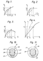
The flow regulating means gives rise to a flow rate/ pressure difference characteristic that has a non-linear portion. Typical flow rate/pressure difference characteristics of arrangements in accordance with the present invention are of the types depicted in Figures 1 to 3 which are plots of flow rate Q against pressure difference Po
-
In these Figures the pressure P represents the pressure difference, or in the case of the characteristic of Figure 2 the maximum pressure difference encountered under normal operating conditions, at which the flow rate is the desired maximum Qo.
-
For the purposes of the present invention, the specified flow rate Qo is deemed to be the maximum flow rate that is desired under normal conditions of use of the arrangement. It will be appreciated that if the flow rate/pressure difference characteristic is of the type shown in Figure 1, higher flow rates than Qo could be obtained if the pressure difference is higher than P .
-
The point X is the point on the characteristic having the co-ordinates Po, Qo.
-
The straight line OX represents the characteristic that would be required to give a flow rate Qo at pressure Po if there was no variation in the flow path resistance with pressure, i.e. if R is constant. It is seen that if Q1 is x.Qo then the condition x.Qo ≼Q ≼Qo is satisfied for pressure differences ranging from P to P2 whereas if R had been constant, providing x > 0, this condition is only satisfied over the smaller pressure difference range P1 to Po.
-
In the case of characteristics of the types shown in Figure 2, the upper pressure difference P2 at which the specified condition is satisfied will exceed the maximum pressure P en- countered under normal operating conditions: in the case of the characteristic of the type shown in Figure 3, the pressure difference P2 may be above or below the maximum encountered under normal operating conditions.
-
It is preferred that the flow regulating means is such that, over a range of pressure differences embracing a pressure difference, e.g. P , at which the flow rate is Q , a 5% increase in the pressure difference effects an increase in resistance to flow of the fluid through the flow path of at least 1%, preferably at least 2%.
-
At low pressure differences, the amount of movement of the moveable element given by an increment in the pressure difference may not have any significant effect on the resistance to flow. Thus the reduction in cross-sectional area of the flow path may be insignificant. In such cases the initial part of the flow rate/pressure difference characteristic may be essentially linear. The slope of this linear portion, for any given fluid, will thus be determined essentially by the dimensions of the part of the flow path incorporating the moveable element with the latter in its zero pressure difference position and by the dimensions of any non-moveable, e.g. non-deformable, portion of the flow path. It is preferred that over such an initial linear portion of the characteristic, a significant part of the resistance to flow is given by such non-moveable portions of the flow path. There will normally be such non-moveable portions both upstream and downstream of the moveable element, and/or there may be a non-moveable member within the moveable element or co-operating therewith.
-
Therefore in accordance with a further aspect of the invention we provide a regulator for mounting within a vessel for regulating the flow of a fluid from the body of said vessel to the outlet thereof comprising at least one non-deformable member and a resiliently moveable member disposed such that, when mounted within said vessel, said resiliently moveable member and said at least one nom-deformable member define the flow path for said fluid from said body of said vessel to said outlet with said resilient member subject to the pressure within said body of said vessel whereby, at least over a range of pressure differences between the pressure in said body of said vessel and the pressure at said outlet, an increase in said pressure difference causes movement of said resiliently moveable member so as to provide an increased resistance to the flow of said fluid through said flow path.
-
It is preferred that the flow path includes a flow restrictor upstream of the moveable element, i.e. between the moveable element and the end of the flow path that is open to the fluid within the body of the vessel. By the term flow restrictor we mean a device across which the pressure drop is a significant proportion of the pressure difference P, at least over the initial linear portion of the flow rate/pressure difference characteristic.
-
The pressure drop across the flow restrictor is preferably at least 5% of the total pressure difference P at pressure differences corresponding to the initial linear portion of the characteristic.
-
Referring to Figure 4 which is a flow rate, Q,/pressure difference, P, plot showing only the initial portion of the characteristic, the point Y represents a point having the co-ordinates P , Qy on the linear portion of the characteristic. The line OF represents the characteristic given by the non-moveable elements of the flow path and the line OD represents the characteristic given by of any non-moveable element of the flow path downstream of the moveable element.
-
At pressure P y therefore, the pressure drop across the non-moveable elements of the flow path is Pf while that across the non-moveable element, if any, downstream of the moveable element is Pd. Hence we prefer that Pf - Pd ≽ 0.05 Py.
-
It will be appreciated that the pressure differences P referred to hereinbefore in relation to Figures 1 to 3 may be above or below the minimum pressure difference at which a 5% increase in the pressure difference causes an increase in resistance to flow of at least 1%.
-
Often it is preferred that the resistance to flow given by a restrictor upstream of the resiliently moveable element is greater than that given by any non-moveable elements of the flow path downstream of the moveable element.
-
Preferably a valve or tap is provided at the outlet of the vessel or downstream thereof to open and shut the flow of fluid through the outlet.
-
In one form of the invention the flow regulator forms part of an assembly for fastening to an opening in the vessel.
-
Therefore in accordance with a further aspect of the invention we provide an assembly for fitting to a vessel to provide a flow path for a fluid from within the body of said vessel to the exterior thereof comprising a closure member adapted to be fastened to said vessel body to close an opening in said vessel, said closure member having a passage therethrough, a flow regulator communicating with the inlet of said passage of said closure member, said regulator and said passage defining said flow path for the fluid from within said body of said vessel to the exterior thereof, said regulator including a resiliently moveable member disposed such that when said closure member is fastened to said vessel body, said resiliently moveable member is within said vessel body and subject to the pressure therein, whereby at least over a range of pressure differences between the pressure within said body of said vessel and the pressure at the outlet of said passage, an increase in said pressure difference causes movement of said element so as to provide an increased resistance to flow of said fluid through said flow path.
-
The above assembly conveniently incorporates an on/off valve, which is actuatable from outside the vessel and is preferably a mechanically actuated valve. The valve conveniently is located to open and close the passage through the closure member.
-
The operation of the invention is now described with reference to Figure 5 which is a diagrammatic section through a container incorporating a flow regulator, for dispensing a liquid. In this embodiment a container 1 having a closure member 2 incorporating an on/off valve 3 has a resiliently walled tube 4 connected to valve 3 mounted within the container 1. A flow restrictor 5, e.g. a length of narrow bore tubing, opening into the fluid e.g. liquid 6 to be dispensed, is connected to the other end of tube 4. The container 1 is pressurised by a gas in the space 7 above liquid 6.
-
Initially, with valve 3 closed, the pressure inside tube 4 equals that exerted by the gas in space 7. On opening valve 3, a pressure drop occurs across the valve 3 causing the liquid inside the tube 4 to be dispensed. The flow of liquid out through valve 3 provides a pressure drop across restrictor 5 causing a flow of liquid 6 through restrictor 5 into tube 4. Because of the pressure drop across restrictor 5, a pressure difference occurs across the walls of tube 4 causing the walls to collapse towards each other. This collapse of tube 4 acts as a further flow restrictor in series with restrictor 5.
-
At the steady state condition it is readily seen that, if the pressure difference between the pressure inside container 1 and that downstream of valve 3 is P, and the pressure differences across valve 3 and restrictor 5 are P
3 and P
5 respectively, then the pressure difference, P
4, across the restriction formed by the collapse of tube 4 is given by:
-
If, at the steady state condition, the volumetric flow rate of the liquid through valve 3 is Q, and the flow is laminar,
where
R31 R
4, and R
5 are the resistances to flow through valve 3, tube 4, and restrictor 5 respectively. Then
R
3 and R
5 are normally largely independent of pressure whereas R
4 will depend on the degree of collapse of tube 4 and hence on the pressure difference across the walls of tube 4.
-
If R. is small in comparison to R
3 + R
5,
i.e. the flow rate is proportional to the overall pressure difference P.
-
The degree of collapse of tube 4, and hence R4, will depend on the pressure difference across the walls of tube 4. This pressure difference is P3 + P4, i.e. P - Q.R3. It is therefore seen that R4 will depend on the overall pressure difference, P, and on the flow rate, Q: the relationship of R4 to P and Q will be determined by the resilience of the walls of tube 4 and the length of that tube and the wall dimensions and configuration. It will be appreciated that the tube 4 does not necessarily collapse uniformly: thus the transition from the uncollapsed state to the collapsed state at one end of the tube may be sharper than at the other end of the tube.
-
When
R4 is large in relation to
R 3 + R
5,
Typical flow rate/pressure difference characteristics are depicted in Figures 1 to 3. Depending on the precise characteristics of tube 4 in relation to those of the rest of the system, i.e. restrictor 5 and valve 3, the overall flow rate
/pressure difference characteristic may be of the form of any of Figures 1, 2, or 3. We have found that, in general, the type of curve, i.e. that of Figure 1, 2, or 3 is largely determined, for any given type of tubing 4, by the length of that tube. As the length increases, the type of characteristic progresses from that of Figure 1 to that of Figure 3 via that of Figure 2.
-
The pressure difference at which the effect of the collapsible tube 4 becomes significant is largely determined by the resilience of the tube walls: As the modulus decreases, this pressure difference reduces.
-
It is therefore seen that by appropriate selection of the length, wall dimensions and configuration, and material, of tube 4, for any given restrictor 5 and valve 3, that above a certain pressure difference the flow rate/pressure difference characteristic can be modified so that there is little change in flow rate for a change in the pressure difference.
-
The invention is of particular utility where the pressure in the vessel is liable to fluctuation. If, as is preferred, the vessel is a container used for dispensing a liquid and is pressurised with a pressurising fluid, e.g. a gas or volatile liquid, pressure fluctuations may occur. Thus where the container is initially charged with the liquid to be dispensed and the pressurising fluid, the pressure exerted by the pressurising fluid may fall simply as a result of the increase in volume occupied by the pressurising fluid as the liquid is dispensed; or pressure fluctuations may occur where the container is pressurised intermittently, eg by a hand pump, or continuously from a source that is liable to pressure fluctuations.
-
It is not essential that the container is pressurised: thus the feed of liquid from the container may simply be a gravity feed. In this case the head of liquid in the container gives rise to the pressure differential to which the moveable element, eog. the walls of the collapsible tubing is subject. Variations in the head of liquid, i.e. as the container empties, thus gives rise to the pressure difference variations for which compensation can be provided by the pressure difference dependent movement of the moveable element.
-
However it is preferred that the vessel is pressurised with a pressurising fluid.
-
One particular application of the invention is where the pressurising fluid is a gas at ambient temperatures and atmospheric pressure but is a liquid at the pressure prevailing within the vessel. These types of pressurising agent, e.g. a flurocarbon such as dichlorodifluromethane or a hydrocarbon such as butane, are widely used as aerosol propellants and the invention is applicable to such aerosol configurations. With this type of pressurising agent, because of the significant changes of vapour pressure of the pressurising agent that occur with relatively small changes in temperature, variations in the ambient temperature can cause considerable variation in the pressure within the vessel: in the absence of apparatus in accordance with the invention, such pressure variations would give rise to substantial variations in the liquid flow rate.
-
For example with a typical pressurising fluid such as dichlorodifluoromethane the gauge pressure within the vessel at an ambient temperature of 10°C is typically about 0.3 MPa whereas at 350C it is about 0.66 MPa. In the absence of the flow regulator of the present invention such a temperature variation would give rise to a flow rate change of a factor of 2 or more.
-
The rate at which the fluid will be dispensed will also depend inversely on the viscosity of the fluid: this viscosity will generally decrease with increasing temperature and so the flow rate will generally increase as the temperature increases. Consequently a flow rate/temperature characteristic of the type shown in Figure 6, which is plot of flow rate Q against temperature T, would be achieved if the flow path had no moveable element. By the provision of a moveable element in the flow path, particularly a resiliently walled portion giving an appropriate flow rate/pressure difference characteristic of the type shown in Figure 3, the change in flow rate with temperature can be markedly reduced.
-
As mentioned hereinbefore, the invention is of particular utility where a liquid is dispensed under the action of a pressurised propellant,e.g. a compressed gas, within the vessel. Where the propellant is a volatile liquid at the pressure prevailing in the vessel and/or has an appreciable solubility in the liquid to be dispensed, on dispensing the liquid some of the propellant may be dispensed with the liquid and may tend to volatilise within the flow path. In some cases this may cause the flow rate/pressure difference characteristic to be modified. In such cases it is preferred that the vessel is arranged such that the propellant cannot be dispe sed with the liquid, e.g. by the use of a barrier pack wherein the liquid to be dispensed is separated from the propellant by a flexible membrane. Thus in one form of construe- tion the liquid to be dispensed is contained within a collapsible bag located within the outer vessel with the propellant fluid in the space between the bag and the outer vessel. In an alternative arrangement the propellant is enclosed within a flexible container within the outer vessel with the liquid to be dispensed in the space between the flexible container and the outer vessel.
-
The invention is of particular utility in aerosol-type packages where the required flow rate is in the range 0.01 to 2.5 ml/sec. The container gauge pressure is preferably within the range 0.03 to 1 MPa.
-
The fluid being dispensed preferably has a viscosity, at the dispensing temperature, of 1.5 x 1074 to 2 Faos, particularly 5 x 10⁻⁴ to 5 x 10⁻² Pa.s.
-
The flow regulator preferably comprises a conduit having a resiliently walled portion as the moveable element. The resiliently walled portion may simply be a length of resilient tubing e.g. tubing of an elastomeric material. However, in order to modify the effect of the pressure difference between the pressure in the vessel and that within the resiliently walled portion on the resistance to flow, the resiliently walled portion may be a sleeve of the resiliently walled material over a non-deformable core member.
-
In a preferred form of the invention, the flow regulator comprises a sleeve of tubing of elastomeric material mounted on a mandrel having one or more grooves or projections along its length. Such grooves or projections serve to define channels for the passage of fluid between the resilient sleeve and the mandrel. As the pressure difference across the walls of the sleeve increases, the sleeve deforms to restrict the channels. It will be appreciated that the slope, size, and position of the grooves or projections will influence the flow ratelpressure difference characteristic. In some cases it may be desirable to provide that there is still a pathway for the passage of fluid when the resilient sleeve has deformed to such an extent that the flow of fluid between the sleeve and the core member is stopped. Such a pathway may be provided by a suitably sized bore through the core member.
-
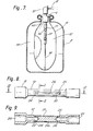
A typical arrangement is shown in Figures 7 to 10. Figure 7 is a longitudinal section through a container fitted with the above type of flow regulator ineorporating an elastomeric sleeve on a mandrel. Figure 8 is an elevation of the mandrel with the sleeve shown dotted. Figure 9 is a longitudinal section of the mandrel along line 1X - 1X of Figure 8 and Figure 10 is a cross section of the mandrel along the line X - X of Figure 8 with the sleeve shown dotted.
-
In this embodiment the container is a barrier pack type aerosol comprising an outer canister 8 to which is crimped or clinched, in conventional fashion, an aerosol valve 9 having a spray button 10 arranged so that depression of button 10 towards valve 9 effects opening of the valve 9 to cause liquid within the canister 8 to be dispensed through valve 9 and through button 10 as a spray 11. The liquid 12 to be dispensed is endorsed within a flexible bag 13 clamped between the fixing of valve 9 to canister 8. Attached to the inlet 14 of valve 9 is one end of a bobbin 15 having a waisted section l6 on which is located a rubber sleeve 17.. Attached to the other end of bobbin 15 is a fine capillary tube restrictor 18. The space 19 between bag 13 and the canister 8 is filled with the propellant.
-
The bobbin 15 is of circular cross section and is provided at each end with blind bores 20, 21 and the waisted portion 16 is provided with diametrically opposed flattened portions 22, 23. Holes 24, 25 drilled through the waisted section 16 connect respectively with bores 20, 21. Between holes 24 and 25, the flats 22, 23 are provided with grooves 26, 27. The rubber sleeve 17, which has an undeformed internal diameter somewhat less than that of the waisted portion 16 so that the rubber sleeve 17 fits tightly thereon, can thus deform, under the action of the pressure difference across the walls of the rubber sleeve, i.e. the pressure difference between the propellant pressure and the pressure within grooves 26, 27, into the grooves 26, 27 to restrict the passage of fluid there through grooves.
-
In a variation shown in Figure 11 which is a cross section of an alternative bobbin construction, instead of grooves 26, 27, each flat 22, 23 of the bobbin is provided with one or more ribs 28 to define the channels for the passage of liquid between the resilient walls of sleeve 17 and the body of the bobbin.
-
One advantage of the present invention, viz the extension of the pressure difference range over which an acceptable flow rate can be achieved, has the result that aerosols of the type where the propellant is a compressed, but not liquified, gas are a viable proposition thus avoiding the mviron- mental objections to the use of liquified gas por such as fluorocarbons or the safety hazards of flammable propellants such as propane or butane
-
In such a compressed, but not liquified, gas propellant system, it is preferred that a barrier pack construction is adopted to avoid wastage of the compressed gas in the event of misuse of the aerosol, e.g. operation of the valve with the container inverted. Alternatively an upstream flow restrictor in the form of a length of flexible capillary tube may be employed with its free end weighted so that that free end is always immersed in the liquid to be dispensed irrespective of the spatial orientation of the container.
-
While the invention is of particular utility in a wide range of aerosol-type dispensing applications, one particular application of the invention is in electrostatic spraying apparatus, for example for agricultural or horticultural use, comprising a portable spray gun including a spray nozzle, means for applying a high electrical potential to said nozzle, and means for supplying to said nozzle liquid to be sprayed from a container of the liquid mounted on the spray gun• Examples of such electrostatic spraying apparatus are described in, inter alia, US-A-4356528. The liquid is supplied to the nozzle from a container containing the liquid and a compressed pressurising agent, e.g. a flurocarbono
-
In this application it is preferred that the container is arranged so that the propellant is not dispensed through the nozzle with the liquid to be sprayed, e.g. by the use of a barrier pack configuration as mentioned hereinbefore. In this way the atomisation of the liquid by the electrostatic forces is not affected by the emergence of the propellant.
-
As mentioned above the pressure exerted by the pressurising agent is liable to considerable fluctuation as the ambient temperature varies, with the result that the liquid supply rate to the nozzle is also liable to considerable fluctuation: indeed over the range of ambient temperatures liable to be encountered in use of the spray gun, particularly where such use is outdoor, the pressure exerted by the pressurising agent, and consequently the flow rate, may vary, in some cases, by a factor of four or more.
-
Variations in flow rate will affect the size, and size distribution, of the liquid droplets formed by electrostatic atomisation. Such variation in droplet size is undesirable since for any given liquid there is an optimum droplet size, or size rauge, for the intended use of the liquid.
-
For example, when spraying plants with a pesticide formulation, if the droplets are too large, the amount of "wrap- round", giving coating on the underside of plant leaves, is reduced; whereas if the droplets are too small, they are liable to be unduly affected by factors such as wind strength and so may drift onto plants other than those intended and/or on to the operator.
-
In such electrostatic spraying systems the desired volumetric flow rates are normally relatively low, typically within the range 0.002 to 0.3 ml/sec. The apparatus of the present invention is particularly suited to such flow rates. Where, as is preferred, a flow restrictor is provided upstream of the resiliently mgveable element in the flow path, this restrictor is typically a length of very fine bore tubing, e.g. 0.5 to 15 cm of tubing of internal diameter 0.1 to 1 mm, or a plug of porous material, whereas the moveable element preferably comprises a length, e.g. 1 to 20 cm, of resiliently walled tubing, typically of internal diameter 2 to 6 mm, of an elastomeric material such as silicone, neoprene, or nitrile, rubber or a plasticised vinyl chloride polymer.
-
Where the moveable element is a resiliently walled tube, this may be of any convenient cross section and may be fluted or provided with a non-deformable core to modify its collapsing characteristics.
-
When used in conjunction with an aerosol-type container (whether or not the liquid in the container is in fact to be atomised upon dispensing) the flow regulator is conveniently attached to or forms part of the inlet of the aerosol valve and includes a flow restrictor upstream of the moveable element, e.g. resiliently walled tube. Where the assembly is of the barrier pack type mentioned hereinbefore, the moveable element and flow restrictor may be wholly or partially within the collapsible inner container: where the moveable element is within the collapsible inner container the pressure exerted by the propellant will be transferred to the moveable element through the liquid within the collapsible inner container.
-
If the vessel outlet is provided with an on/off valve, and the resistance R3 given by the outlet port when the valve is open is relatively small, the system can act as a metering valve to dispense a predetermined quantity of the liquid. Thus, referring to the system of Figure 5, since when the valve 3 is closed there is no flow, the pressure drop, P5, across restrictor 5 is zero and so the pressure inside the collapsible tube 4 equals that, P, outside the collapsible tube 4: therefore the walls of tube 4 are not collapsed, i.e. are as shown dotted in Figure 5. A predetermined amount of the liquid is thus located within tube 4 between restrictor 5 and valve 3. This amount will depend on the dimensions of tube 4. On opening the valve 3, if the resistance R3 is small, this predetermined amount of liquid will be dispensed rapidly, causing the pressure within tube 4 to fall. The pressure difference across the walls of tube 4 thus increases from zero, causing the walls to collapse, possibly even to the extent of totally sealing tube 4. As the liquid is dispensed from tube 4 via port 2, the pressure difference across restrictor 5 increases from zero, thus causing flow of liquid through restrictor 5 into tube 4, thereby tendiag to reduce the pressure difference across the walls of tube 4. If valve 3 is closed before tube 4 has refilled to any appreciable extent via restrictor 5, it will be seen that only the predetermined amount of liquid will be dispensed.
-
The invention is also of utility as a flow regulator in a fluid flow line where the pressure difference between the ends thereof is liable to fluctuation, e.g. as a result of a varying hydrostatic head. In this case the flow regulator of the invention can be employed as an insert in the flow line: the vessel here comprises part of the flow line to which the liquid is continuously supplied.
-
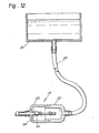
An example of this form of the invention is illustrated in Figure 12 which an elevation, part in section, of a flow line incorporating such a flow regulator.
-
In this embodiment a liquid is supplied via an inlet line 29 from a source 30, which may simply be a reservoir giving a gravity feed, to a casing 31.
-
The casing 31 comprises two mouldings 32, 33 which snap-fit together to form a liquid-tight enclosure. To the outlet port 34 in one of the mouldings is fitted a conduit incorporating a resiliently walled portion 35. This conduit conveniently comprises a bobbin assembly of the type shown in Figures 8 - 10.
-
It is seen that variation in the hydrostatic head between source 30 and casing 31 gives rise to a variation in the pressure within casing 31 which can thus give rise to a variation in the resistance to flow given by the resiliently walled portion of the conduit.
-
It is preferred that the flow regulator is located towards the outlet end of the liquid flow line.
-
One possible application of this embodiment of the invention is as a flow regulator for medical uses where the liquid is for example blood or a saline solution being supplied to a patient.
-
The invention is illustrated by the following Examples.
EXAMPLE 1
-
In this example the arrangement of Figures 7 - 10 was employed but omitting the bag 13. The canister was connected to a source of compressed air.
-
The dimensions of the bobbin were as follows:
- length of bores 20, 21 17 mm diameter of narrow portions of
-
The sleeve 17 was a 22 mm length of neoprene rubber tube (laboratory size N3 - British Standard 2775/67) having, in the free state, i.e. unstretched and before mounting on the bobbin 15, an internal diameter of 3 mm and a wall thickness of 0.75 mm.
-
The upstream restrictor 18 was a length, approximately 1 cm of 0.25 mm internal diameter nylon capillary tubing.
-
The canister was filled with a pesticidal composition of 5 x 14-3 Pa.s viscosity at room temperature and pressurised with compressed air to various pressures. The flow rate at the various pressures was measured.
-
The results are shown in the following table.
It is seen from the above results that the flow rate/pressure difference characteristic was virtually of the type shown in Figure 2. The flow rate is within 80% of the maximum flow rate for all pressures, at least up to the maximum tested, above about 0.145 MPa.
EXAMPLE 2
-
Example 1 was repeated but replacing the bobbin/ capillary tube restrictor by a 175 mm length of the neoprene tubing to the free end of which a flow restrictor was fitted. The flow restrictor was a metal cup of about 3 mm internal diameter and 1 cm height having a base of 0.5 mm thickness with a 0.5 mm diameter hole therethrough.
-
In this example the liquid was water (viscosity approx 10
-3 Pa.s.).
-
It is seen that the flow rate is within 15% of the maximum for all pressures, at least up to the maximum pressure tested, above about 0.06 MFa.
-
When the rubber tube and metal cup flow restrictor were replaced by a rigid tube of 4 mm internal diameter and 170 mm length, so that the restriction to flow was essentially that presented by the aerosol valve, the flow rate at 0.28 MPa gauge pressure was about 1.9 ml.s-1 .