EP0134129A2 - Device for uniting components one to another - Google Patents
Device for uniting components one to another Download PDFInfo
- Publication number
- EP0134129A2 EP0134129A2 EP84305349A EP84305349A EP0134129A2 EP 0134129 A2 EP0134129 A2 EP 0134129A2 EP 84305349 A EP84305349 A EP 84305349A EP 84305349 A EP84305349 A EP 84305349A EP 0134129 A2 EP0134129 A2 EP 0134129A2
- Authority
- EP
- European Patent Office
- Prior art keywords
- adhesive
- membrane
- component
- bag
- opening
- Prior art date
- Legal status (The legal status is an assumption and is not a legal conclusion. Google has not performed a legal analysis and makes no representation as to the accuracy of the status listed.)
- Granted
Links
Images

Classifications
-
- B—PERFORMING OPERATIONS; TRANSPORTING
- B65—CONVEYING; PACKING; STORING; HANDLING THIN OR FILAMENTARY MATERIAL
- B65D—CONTAINERS FOR STORAGE OR TRANSPORT OF ARTICLES OR MATERIALS, e.g. BAGS, BARRELS, BOTTLES, BOXES, CANS, CARTONS, CRATES, DRUMS, JARS, TANKS, HOPPERS, FORWARDING CONTAINERS; ACCESSORIES, CLOSURES, OR FITTINGS THEREFOR; PACKAGING ELEMENTS; PACKAGES
- B65D33/00—Details of, or accessories for, sacks or bags
- B65D33/16—End- or aperture-closing arrangements or devices
- B65D33/1691—End- or aperture-closing arrangements or devices using adhesive applied to attached closure elements
-
- B—PERFORMING OPERATIONS; TRANSPORTING
- B65—CONVEYING; PACKING; STORING; HANDLING THIN OR FILAMENTARY MATERIAL
- B65D—CONTAINERS FOR STORAGE OR TRANSPORT OF ARTICLES OR MATERIALS, e.g. BAGS, BARRELS, BOTTLES, BOXES, CANS, CARTONS, CRATES, DRUMS, JARS, TANKS, HOPPERS, FORWARDING CONTAINERS; ACCESSORIES, CLOSURES, OR FITTINGS THEREFOR; PACKAGING ELEMENTS; PACKAGES
- B65D33/00—Details of, or accessories for, sacks or bags
- B65D33/16—End- or aperture-closing arrangements or devices
- B65D33/18—End- or aperture-closing arrangements or devices using adhesive applied to integral parts, e.g. to flaps
- B65D33/20—End- or aperture-closing arrangements or devices using adhesive applied to integral parts, e.g. to flaps using pressure-sensitive adhesive
Definitions
- a bag 63 comprising a front panel 64, a rear panel 65 and a flap 66 extending downwardly from an upper marginal edge of the front and rear panels 64, 65, an upper edge portion of the flap 66 being welded to corresponding upper edge portions of the front and rear panels 64, 65 to provide an upper weld 67.
- the flap 66 is provided with a slot 68 extending substantially parallel to the upper weld 67, the slot 68 being bridged by an adhesive tape 69 extending longitudinally of the slot 68.
- the adhesive of the tape 69 is a "re-usable" adhesive.
- the front panel 64 is provided with a line of weakening 70 extending substantially parallel to the slot 68 and located in a direction downwardly from the weld 67 between the slot 68 and the weld 67.
- the marginal portions of the tape may each be provided with a plurality of folds, as with the tape 115 shown in Figure 16, whereby the folded marginal portions 116 and 117 provide a resilient bias such that an adhesive surface 118 is urged in a direction away from an opposite facing surface 119 of the bag.
- the surface 125 of the label 120 thus may be located adjacent a support surface while the surface 122 has indicia entered thereon without the label 120 adhering to the supporting surface.
Abstract
Description
- This invention relates to a device for uniting components one to another and may comprise a closure for a bag.
- It is known to provide open bags made of synthetic plastics film material in which contents are inserted and the bags subsequently closed.
- Various forms of closure have been used and proposed for such bags and a common form of closure comprises a portion of pressure sensitive contact adhesive provided on a surface of the material of which a bag is formed the adhesive being located at an opening of the bag.
- A disadvantage of bags having closure means in the form of pressure sensitive contact adhesive is that it is necessary to mask the adhesive during transit and storage of the bags prior to use, the bags generally being stacked, since otherwise the bags will adhere one to another. Masking of adhesive generally is effected by covering the adhesive with a tape having a release coating in contact with the adhesive so that, when it is necessary to effect closure of a bag, the masking tape can be peeled from the adhesive, which remains on the material of the bag, to expose the adhesive.
- Apart from the cost of providing masking tape, bags having masking tape covering adhesive closure means have a disadvantage in that it is necessary to remove the masking tape before closure of a bag can be effected. It is desirable, therefore, to provide a device for uniting components one to another which device may comprise a closure for a bag in which pressure sensitive contact adhesive is not covered by masking tape and thereby is less expensive to produce and less time consuming to effect closure thereof compared with closures for bags known hitherto.
- One such device is known which comprises a first component, such as a panel of a bag, a second component, such as a second panel of the bag facing the first panel, the second component having an elongate opening therein and a membrane having pressure sensitive contact adhesive thereon, the membrane being united with a first surface of the second component such that the adhesive bridges the opening and contacts the surface of the first component through the opening when that surface is adjacent the second surface of the second component remote from the membrane. An example of such a device is described in French patent specification No. 2,345,355 (Janowski) with reference to Figure 1 of the drawings accompanying that specification.
- A disadvantage of such device is that whenever the said surface of the first component, or indeed any other surface of another component for example, is located adjacent the second surface of the second component, the said surface of the first component is contacted by the adhesive. If the first and second components are panels of a bag, such contact can result in premature and unwanted closing of the bag or, if the other surface comprises a surface of an article being inserted into or removed from the bag, in contamination of the article by the adhesive and/or contamination of the adhesive by the article.
- The invention is characterised in that the dimensions of the opening are such that, when the components are located such that a surface of the first component is adjacent a surface of the second component remote from the membrane, the adhesive is spaced from contact with the said surface of the first component but is contactable therewith by deforming a portion of the first component or a portion of the membrane into the opening.
- In this manner, premature contacting of the said surface of the first component, or any other surface of another article, by the adhesive is avoided since such contact is only effected by the positive act of deforming a portion of the first component or a portion of the membrane into the opening.
- Following is a description, by way of example only and with reference to the accompanying drawings, of one method of carrying the invention into effect. In the drawings :-
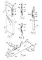
- FIGURE 1 is a diagrammatic representation, shown partly in cross section, of a bag provided with one embodiment of a device in accordance with the present invention,
- FIGURE 2 is a diagrammatic cross section of portions of opposite facing panels of a bag provided with a modification of the embodiment of the device shown in Figure 1, the device being in an open condition,
- FIGURE 3 is a view similar to Figure 2 showing the device in a closed position,
- FIGURE 4 is a diagrammatic representation showing a method of manufacturing bags provided with a device in accordance with the present invention,
- FIGURE 5 is a diagrammatic representation of another embodiment of a device in accordance with the present invention,
- FIGURES 6 to 11 inclusive are diagrammatic representations of different bags each provided with one or more devices in accordance with the present invention,
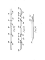
- FIGURES 12 and 13 are diagrammatic representations of steps in an alternative method of manufacturing bags each provided with a device in accordance with the present invention,
- FIGURE 14 is a diagrammatic representation of a bag made in accordance with the method represented diagrammatically in Figures 12 and 13.
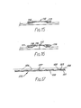
- FIGURE 15 is a diagrammatic cross section, similar to Figure 2 but turned through 90°, of another embodiment of a device in accordance with the present invention,
- FIGURE 16 is a diagrammatic cross section similar to Figure 15 of another embodiment of a device in accordance with the present invention, and
- FIGURE 17 is a diagrammatic cross section of a label incorporating a device in accordance with the present invention.
- Referring now to Figure 1 of the drawings, there is shown a diagrammatic representation of a
bag 10 formed of a sheet of synthetic plastics film material having abottom fold 11, afront panel 12 and arear panel 13. Upper portions of the front andrear panels fold 11 define an opening 14 of thebag 10. Thefront panel 12 is slit in a direction extending substantially parallel to thefold 11, opposite marginal portions of the material of thefront panel 12 defining the slit being folded outwardly of thefront panel 12 and away from one another to form outwardly turnedfolds slot 17 extending substantially parallel to thebottom fold 11 of thebag 10. Theslot 17 and thefolds adhesive tape 18, the tape extending longitudinally of theslot 17 and transversely beyond thefolds tape 18 adheres to thefolds front panel 12 and is exposed to an inner surface of therear panel 13 through theslot 17. The front andrear panels tape 18 and thefolds bottom fold 11 of the bag. - The arrangement is such that the dimensions of the
slot 17 are such that an inner surface of an upper portion of therear panel 13 can be located adjacent to, or even in contact with, an inner surface of thefront panel 12 without the adhesive of thetape 18 exposed through theslot 17 contacting an opposite facing portion of the inner surface of therear panel 13. Contact of the adhesive of thetape 18 through theslot 17 with a portion of an inner surface of therear panel 13 is effected only by deforming the surface of therear panel 13 in a longitudinal direction of theslot 17 so that a longitudinally extending portion of therear panel 13 in a direction of theslot 17 enters theslot 17 and adheres to the adhesive of thetape 18 thereby to effect closure of thebag 10. - Alternatively, the material of the
tape 18 may be deformed longitudinally of theslot 17 so as to extend through the slot and contact an opposite facing portion of the inner surface of therear panel 13. - It is preferred, however, that the
adhesive tape 18 be of "stiff" material and that closure of thebag 10 is effected by deforming an upper portion of therear panel 13 longitudinally of theslot 17. - It will be appreciated that the adhesive of the
tape 18 may be a "permanent" adhesive whereby, once thebag 10 is closed, it cannot subsequently be opened without destroying the material of the bag. Alternatively, the adhesive of thetape 18 may be "re-usable" such that the bag may be opened and re-closed and repeatedly re-opended and re-closed. - It would also be appreciated that the
folds tape 18 through theslot 17 and an opposite facing adjacent portion of the inner surface of therear panel 13. - Referring now to Figures 2 and 3 of the drawings, there is shown front and
rear panels rear panels bag 10, wherein thefront panel 19 is slit and opposite marginal portions defining the slit are curled away from one another to providemulti-layer folds slot 23. Theslot 23 is bridged byadhesive tape 24. - The arrangement is such that the
multi-layered folds adhesive tape 24 and therear panel 20 whereby the dimension of theslot 23 in a direction between themulti-layered folds tape 24 and therear panel 20 one to another. - Referring now to Figure 4 of the drawings, there is shown, diagrammatically, a method of forming bags shown in Figures 1 to 3. In the method, a
web 25 has been folded longitudinally at 26 to form anupper layer 27 superimposed on alower layer 28, the layers being of equal dimension, and theweb 25 being wound to form areel 29. The foldedweb 25 is unwound from thereel 29 and is advanced towards ablade 30 which slits theupper layer 27 longitudinally adjacent a marginal edge thereof remote from thelongitudinal fold 26. The longitudinal marginal portions defining the slit are folded outwardly in opposite directions transversely of the direction of movement of theweb 25 by means of a tool (not shown) to form outwardly oppositely folded longitudinally extendingfolds folds adhesive tape 33 unwound from areel 34 located above theweb 25, the adhesive of thetape 33 contacting thefolds - The folded and
slit web 25 having the adhesive tape applied thereto subsequently is advanced to a severing station (not shown) whereby the web and thetape 33 adhered thereto are severed transversely of the direction of movement of theweb 25 such that the web andtape 33 are cut and provided with spaced substantially parallel transversely extending seams to form completed bags. - Referring now to Figure 5 of the drawings, there is shown in diagrammatic cross section, another embodiment of a
bag 35 having front andrear panels front panel 36 of thebag 35 is not slit and the marginal portions thereof folded to provide a slot. Instead, afront panel 36 of thebag 35 is provided with aslot 38 and a pair offilaments slot 38 and are secured to an outer surface of thefront panel 36 by means of an adhesive tape 40a which bridges theslot 38 and adheres to thefilaments front panel 36. - Referring now to Figure 6 of the drawings, there is shown a
bag 41 similar to thebag 10, thebag 41 having afront panel 42, arear panel 43 and abottom fold 44. Therear panel 43 is of a dimension in an upward direction from thebottom fold 44 which is greater than the upward dimension of thefront panel 42 to provide a portion which is folded inwardly prior to provision of the spaced side seams, one of which is shown at 45, to provide an inwardly directedflap 46 extending rearwardly of aslot 47 in thefront panel 42, whichslot 47 is bridged by a longitudinally extending strip of pressuresensitive contact adhesive 48. The adhesive 48 is "re-usable". - Referring now to Figure 7 of the drawings, there is shown a
bag 49 comprising front andrear panels bottom fold 52. Thefront panel 50 extends in an upward direction from the bottom fold 52 a distance greater than therear panel 51 and the portion of thefront panel 50 extending above and beyond therear panel 51 is provided with aslot 53 which is bridged byadhesive tape 54. Access to the bag is from above, as indicated by the arrow in Figure 7, and the bag is closed by folding the portion of thefront panel 50 extending above and beyond therear panel 51 rearwardly of and downwardly behind therear panel 51 whereby theadhesive 54 exposed through theslot 53 is applied to an outer surface of therear panel 51. Thetape 54 may be provided with "permanent" or "re-usable" adhesive. - Referring now to Figure 8 of the drawings, there is shown a carrier bag 55 which is similar in construction to the
bag 41 shown in Figure 6 in that the bag 55 is provided with afront panel 56, a rear panel 57 abottom fold 58, an inwardly directedflap 59 and a strip of pressure sensitive contactadhesive tape 60 extending longitudinally of and bridging a slot (not shown) in thefront panel 56. The adhesive of thetape 60 is a "permanent" adhesive. - Unlike the
bag 41 in Figure 6, however, the bag 55 is provided withhand slots 61 in the front andrear panels flap 59 and is also provided with a line of weakening 62 in an upper portion of theflap 59 extending substantially parallel to thebottom fold 58. - The arrangement is such that, when an article is, or articles are, inserted into the bag 55, the bag is closed by means of the adhesive of the
tape 60 adhering to an opposite facing surface of theflap 59 and the bag 55 subsequently can only be opened by severing the material of theflap 59 longitudinally of the line of weakening 62. - In consequence, the bag 55 provides means whereby, once articles have been purchased in a retail establishment, inserted into the bag 55 and the bag closed by means of the adhesive 60, the bag cannot subsequently be re-opened and further articles inserted therein without it being apparent that the bag previously had been closed by the adhesive 60 to seal therein the earlier purchased articles.
- It will be appreciated that the presence of the
tape 60 provides reinforcement to the bag 55 and inhibits tearing of the material of the bag which would tend to occur during transportation of a bag when loaded. - Referring now to Figure 9 of the drawings there is shown a
bag 63 comprising afront panel 64, arear panel 65 and aflap 66 extending downwardly from an upper marginal edge of the front andrear panels flap 66 being welded to corresponding upper edge portions of the front andrear panels upper weld 67. Theflap 66 is provided with aslot 68 extending substantially parallel to theupper weld 67, theslot 68 being bridged by anadhesive tape 69 extending longitudinally of theslot 68. The adhesive of thetape 69 is a "re-usable" adhesive. Thefront panel 64 is provided with a line of weakening 70 extending substantially parallel to theslot 68 and located in a direction downwardly from theweld 67 between theslot 68 and theweld 67. - The
bag 63 is inverted so that contents may be inserted therein and the marginal edge portions of the front andrear panels upper weld 67 are welded so as to envelop the contents. The filledbag 63 subsequently is returned to the position shown in Figure 9 for storage. - Opening of the
bag 63 is effected by separating theflap 66 from the front panel 64 (united one with another by means of the adhesive tape 69) and severing the material of thefront panel 64 longitudinally of the line ofweakening 70. - It will be appreciated, therefore, that the
bag 63, in providing the line of weakening 70, incorporates a "tamper evident" feature. - Referring now to Figure 10 of the drawings there is shown a
bag 71 which is similar to the bag shown in Figure 6 except that thebag 71 is formed of separate front andrear panels panels flap 74 of thebag 71 is united with an inner surface of thefront panel 72 by means of anadhesive tape 75 bridging and extending longitudinally of aslot 76 in thefront panel 72. - The
bag 71 is inverted from the position shown in Figure 10 and contents are inserted therein in a direction of the arrow in Figure 10. Subsequently, opposite facing marginal edges of the front andrear panels flap 74 are welded one to another to envelop the contents and thebag 71 then is returned to the position shown in Figure 10 for storage. Opening and closing of the bag is effected in the same manner as described with reference to thebag 41 shown in Figure 6. - Referring now to Figure 11 of the drawings, there is shown a
bag 77 which is similar in configuration to thebag 49 shown in Figure 7 in that thebag 77 is provided with afront panel 78 which extends upwardly from abottom fold 79 beyond arear panel 80 to provide aflap 81. Theflap 81 is provided with a slot (not shown) extending substantially parallel to thebottom fold 79, the slot being bridged byadhesive tape 82 the adhesive of which is a "permanent" adhesive. - Unlike the
bag 49 shown in Figure 7, however, abag 77 is provided with a line of weakening 83 extending below and substantially parallel to thetape 82 and therear panel 80 also is provided with aslot 84 extending substantially parallel to the slot in theflap 81. Theslot 84 is bridged byadhesive tape 85 extending longitudinally of theslot 84, the adhesive of thetape 85 being "re-usable". - Contents are inserted into the
bag 77 in the direction of the arrow shown in Figure 11 and, subsequently, theflap 81 is folded rearwardly behind therear panel 80 and adheres, by means of theadhesive tape 82, to the rear surface of the rear panel. The bag can be opened only by severing the material of a bag longitudinally of the line ofweakening 83. After having been thus opened, the configuration of thebag 77 is similar to thebag 10 shown in Figure 1. The configuration of thebag 77 thus provides a "tamper evident" feature. - Referring now to Figures 12 to 14 of the drawings, there is shown a further embodiment of a bag having a device in accordance with the present invention and a method of manufacturing such a bag.
- Unlike the method illustrated diagrammatically in Figure 4 of the drawings, the method of manufacturing bags shown in Figures 12 and 13 results in four continuous streams of bags being manufactured simultaneously. The method is achieved by providing two
webs web 86 being superimposed on theweb 87. Thewebs - Initially, the
lower web 87 is slit at four locations shown at 88, 89, 90 and 91, the material of theweb 87 being folded outwardly and the folds having applied thereto correspondingadhesive tapes web 87. Simultaneously with slitting of thelower web 87, theupper web 86 also is slit at two locations extending transversely of theweb 86 and the material of theweb 86 is folded inwardly to form inwardly directed flaps 96, 97, 98 and 99, adjacent surfaces of theflaps 96 to 99 corresponding to theadhesive tapes 92 to 95 adhereing to the respective tapes. Theflaps 96 to 99 are each provided with heat seals extending longitudinally of theweb 86, as shown at 100, 101, 102 and 103 respectively. Thewebs welds lower web 87 is severed longitudinally at two locations between opposite pairs offlaps weld 105 also is slit longitudinally. The longitudinally slit and weldedwebs bag 41 shown at Figure 6 except that theinner flap 109 is provided with alongitudinally extending weld 110 substantially parallel to abottom fold 111. - The configuration of the bag shown in Figure 14 is particularly adapted for containing coins whereby the portion of the bag outwardly of the
weld 110 provides a finger tab which, in a filled bag, would extend radially outwardly of a bulbous configuration of a filled bag. The finger tab enables a filled bag to be grasped and easily opened. - It will be appreciated that, instead of folding the material of a bag adjacent a slot which is bridged by the adhesive tape to provide
folds parallel filaments adhesive tape 112 are folded towards one another so that the adhesive on the margins contacts adjacent areas of adhesive between the margins to provide spaced parallel longitudinally extendingmarginal spacers - The marginal portions of the tape may each be provided with a plurality of folds, as with the
tape 115 shown in Figure 16, whereby the foldedmarginal portions adhesive surface 118 is urged in a direction away from an opposite facingsurface 119 of the bag. - It will also be appreciated that a device in accordance with the present invention need not comprise a closure for a bag. In Figure 17, for example, there is shown a
label 120 comprising asheet 121 having anouter surface 122 and aninner surface 123. Theinner surface 123 has coated thereon a pressuresensitive adhesive 124. Thesurface 124 has located thereon asheet 125 having a plurality ofopenings 126 such as slits, slots or rows of perforations. - In use, the
label 120 is attached to asurface 127 by pressing thelabel 120 onto thesurface 127 with thesheet 125 in contact with thesurface 127. The effect is that thesheet 121 is deformed, whereby portions of theadhesive coating 124 adjacent theopenings 126 are projected so as to adhere to portions of thesurface 127 adjacent theopenings 126. Unless a pressing force is applied to thelabel 120, the dimensions of theopenings 126 are such that relative movement of the surface of thesheet 125 remote from the adhesive 124 and any other surface will not result in adhesive contact being effected between the surfaces. - The
surface 125 of thelabel 120 thus may be located adjacent a support surface while thesurface 122 has indicia entered thereon without thelabel 120 adhering to the supporting surface. - It will be appreciated, therefore, that a device in accordance with the present invention when provided in the form of a label is less expensive than a comparable label having a peelable masking sheet coated with a release substance for contacting the adhesive.
- The material which carries the adhesive in any of the embodiments refered to above may be such that the material is deformable repeatedly to different configurations, each configuration being maintained until the material is deformed to a different configuration. If such material is folded, for example, the material remains in the folded condition, a so called 'dead fold', until the material is re-folded or smoothed out. An example of materials which possess such characteristics are metal foils.
Claims (15)
Priority Applications (1)
| Application Number | Priority Date | Filing Date | Title |
|---|---|---|---|
| AT84305349T ATE43315T1 (en) | 1983-08-25 | 1984-08-07 | DEVICE FOR CONNECTING TWO COMPONENTS. |
Applications Claiming Priority (2)
| Application Number | Priority Date | Filing Date | Title |
|---|---|---|---|
| GB8322884 | 1983-08-25 | ||
| GB838322884A GB8322884D0 (en) | 1983-08-25 | 1983-08-25 | Uniting components one to another |
Publications (3)
| Publication Number | Publication Date |
|---|---|
| EP0134129A2 true EP0134129A2 (en) | 1985-03-13 |
| EP0134129A3 EP0134129A3 (en) | 1986-05-28 |
| EP0134129B1 EP0134129B1 (en) | 1989-05-24 |
Family
ID=10547861
Family Applications (1)
| Application Number | Title | Priority Date | Filing Date |
|---|---|---|---|
| EP84305349A Expired EP0134129B1 (en) | 1983-08-25 | 1984-08-07 | Device for uniting components one to another |
Country Status (11)
| Country | Link |
|---|---|
| US (1) | US4633508A (en) |
| EP (1) | EP0134129B1 (en) |
| JP (1) | JPS6090140A (en) |
| AT (1) | ATE43315T1 (en) |
| AU (1) | AU577238B2 (en) |
| CA (1) | CA1230094A (en) |
| DE (1) | DE3478298D1 (en) |
| DK (1) | DK160478C (en) |
| GB (1) | GB8322884D0 (en) |
| IL (1) | IL72652A (en) |
| ZA (1) | ZA846609B (en) |
Cited By (6)
| Publication number | Priority date | Publication date | Assignee | Title |
|---|---|---|---|---|
| FR2681581A1 (en) * | 1991-09-25 | 1993-03-26 | Decomatic Sa | Tamper-evident envelope with adhesive closure |
| GB2265883B (en) * | 1989-06-08 | 1994-02-16 | Mcg Venus Packaging Limited | A bag |
| WO1995013225A1 (en) * | 1993-11-12 | 1995-05-18 | H D Plastics Limited | Sealable bag or like container |
| US5918983A (en) * | 1996-11-08 | 1999-07-06 | Control Paper Co., Inc. | Security envelope |
| US6190043B1 (en) | 1999-11-23 | 2001-02-20 | Jonathan Diplock | Front opening plastic secure package with false panel |
| US6431752B1 (en) | 1999-11-23 | 2002-08-13 | Jonathan Diplock | Plastic coin transport bag |
Families Citing this family (12)
| Publication number | Priority date | Publication date | Assignee | Title |
|---|---|---|---|---|
| GB8322885D0 (en) * | 1983-08-25 | 1983-09-28 | Sanders B | Containers |
| US5044772A (en) * | 1987-04-28 | 1991-09-03 | Minnesota Mining And Manufacturing Company | Flexible bag with supporting and sealing tape |
| US5401533A (en) * | 1991-11-08 | 1995-03-28 | Sealright Co., Inc. | Method of making resealable packaging material |
| CA2148284A1 (en) * | 1992-10-30 | 1994-05-11 | Ole Oestergaard | Method for manufacturing a film, a bag made from a film, such a film |
| US5474229A (en) * | 1994-10-04 | 1995-12-12 | Shimazaki; Junji J. | Method and apparatus for stacking pressure-sensitive adhesive envelopes |
| US5558438A (en) * | 1995-07-10 | 1996-09-24 | Rex-Rosenlew International Incorporated | Bag with reenforced handle and resealable pour spout opening |
| US6149304A (en) * | 1997-05-09 | 2000-11-21 | The Procter & Gamble Company | Flexible storage bag with selectively-activatible closure |
| US6467957B2 (en) * | 2000-02-03 | 2002-10-22 | Innoflex Incorporated | Adhesive closure strip, bag and method |
| US6461044B1 (en) | 2000-06-12 | 2002-10-08 | Sonoco Development, Inc. | Reclosable bag formed on form, fill and seal machine |
| US6805486B2 (en) * | 2002-06-04 | 2004-10-19 | Ykk Corporation Of America | Closure system |
| US9919844B2 (en) | 2014-04-02 | 2018-03-20 | Peter Taylor | Sealable bag |
| US20190112116A1 (en) * | 2017-10-17 | 2019-04-18 | Ips Industries, Inc. | Reusable tamper-evident bag |
Citations (6)
| Publication number | Priority date | Publication date | Assignee | Title |
|---|---|---|---|---|
| FR1194330A (en) * | 1959-11-09 | |||
| US3085738A (en) * | 1959-08-10 | 1963-04-16 | Bok Edward | Flat bag with an adhesive seal |
| US3256941A (en) * | 1964-09-23 | 1966-06-21 | Gulf Oil Corp | Bag closure |
| DE2526014A1 (en) * | 1975-06-11 | 1976-12-30 | Hans Lehmacher | Plastics bag reinforcement attachment - has separate foil strips welded around hand holes in carrier sides |
| FR2373391A1 (en) * | 1976-12-09 | 1978-07-07 | Flexico France Sarl | Continuous mfr. of polypropylene bags with an adhesive closure - using an incompatible strip to cover the adhesive |
| US4415087A (en) * | 1981-12-30 | 1983-11-15 | Mobil Oil Corporation | Laminated pressure sensitive adhesive strip for use in plastic bags |
Family Cites Families (10)
| Publication number | Priority date | Publication date | Assignee | Title |
|---|---|---|---|---|
| US3128936A (en) * | 1964-04-14 | Heat sealable container | ||
| US2991001A (en) * | 1959-04-06 | 1961-07-04 | William L Hughes | Resealable container |
| US3079066A (en) * | 1960-12-21 | 1963-02-26 | Continental Can Co | Temporary sealing means for bags |
| GB1063862A (en) * | 1963-07-08 | 1967-03-30 | Eric William Platt | Process for manufacturing a flexible re-sealable container |
| US3339606A (en) * | 1966-06-14 | 1967-09-05 | Kugler Emanuel | Slide closure |
| JPS5212184B2 (en) * | 1971-08-26 | 1977-04-05 | ||
| CA952487A (en) * | 1971-12-10 | 1974-08-06 | James L. Cameron | Recloseable bag with pressure sensitive closure |
| JPS5637979Y2 (en) * | 1975-07-11 | 1981-09-04 | ||
| JPS5841160Y2 (en) * | 1980-01-14 | 1983-09-17 | 克幸 三輪 | Bag with an opening that can be opened and closed |
| GB8322885D0 (en) * | 1983-08-25 | 1983-09-28 | Sanders B | Containers |
-
1983
- 1983-08-25 GB GB838322884A patent/GB8322884D0/en active Pending
-
1984
- 1984-08-07 AT AT84305349T patent/ATE43315T1/en not_active IP Right Cessation
- 1984-08-07 DE DE8484305349T patent/DE3478298D1/en not_active Expired
- 1984-08-07 EP EP84305349A patent/EP0134129B1/en not_active Expired
- 1984-08-12 IL IL72652A patent/IL72652A/en not_active IP Right Cessation
- 1984-08-20 CA CA000461368A patent/CA1230094A/en not_active Expired
- 1984-08-21 AU AU32232/84A patent/AU577238B2/en not_active Ceased
- 1984-08-22 DK DK401384A patent/DK160478C/en active
- 1984-08-22 JP JP59174865A patent/JPS6090140A/en active Granted
- 1984-08-22 US US06/643,282 patent/US4633508A/en not_active Expired - Lifetime
- 1984-08-24 ZA ZA846609A patent/ZA846609B/en unknown
Patent Citations (6)
| Publication number | Priority date | Publication date | Assignee | Title |
|---|---|---|---|---|
| FR1194330A (en) * | 1959-11-09 | |||
| US3085738A (en) * | 1959-08-10 | 1963-04-16 | Bok Edward | Flat bag with an adhesive seal |
| US3256941A (en) * | 1964-09-23 | 1966-06-21 | Gulf Oil Corp | Bag closure |
| DE2526014A1 (en) * | 1975-06-11 | 1976-12-30 | Hans Lehmacher | Plastics bag reinforcement attachment - has separate foil strips welded around hand holes in carrier sides |
| FR2373391A1 (en) * | 1976-12-09 | 1978-07-07 | Flexico France Sarl | Continuous mfr. of polypropylene bags with an adhesive closure - using an incompatible strip to cover the adhesive |
| US4415087A (en) * | 1981-12-30 | 1983-11-15 | Mobil Oil Corporation | Laminated pressure sensitive adhesive strip for use in plastic bags |
Cited By (7)
| Publication number | Priority date | Publication date | Assignee | Title |
|---|---|---|---|---|
| GB2265883B (en) * | 1989-06-08 | 1994-02-16 | Mcg Venus Packaging Limited | A bag |
| FR2681581A1 (en) * | 1991-09-25 | 1993-03-26 | Decomatic Sa | Tamper-evident envelope with adhesive closure |
| WO1995013225A1 (en) * | 1993-11-12 | 1995-05-18 | H D Plastics Limited | Sealable bag or like container |
| US5918983A (en) * | 1996-11-08 | 1999-07-06 | Control Paper Co., Inc. | Security envelope |
| US6190043B1 (en) | 1999-11-23 | 2001-02-20 | Jonathan Diplock | Front opening plastic secure package with false panel |
| US6431752B1 (en) | 1999-11-23 | 2002-08-13 | Jonathan Diplock | Plastic coin transport bag |
| US6886980B1 (en) | 1999-11-23 | 2005-05-03 | Jonathan Diplock | Plastic coin bag |
Also Published As
| Publication number | Publication date |
|---|---|
| DK160478B (en) | 1991-03-18 |
| DK160478C (en) | 1991-08-26 |
| JPS6090140A (en) | 1985-05-21 |
| EP0134129A3 (en) | 1986-05-28 |
| JPH0455943B2 (en) | 1992-09-04 |
| US4633508A (en) | 1986-12-30 |
| AU577238B2 (en) | 1988-09-15 |
| ATE43315T1 (en) | 1989-06-15 |
| EP0134129B1 (en) | 1989-05-24 |
| GB8322884D0 (en) | 1983-09-28 |
| DE3478298D1 (en) | 1989-06-29 |
| IL72652A (en) | 1990-12-23 |
| CA1230094A (en) | 1987-12-08 |
| ZA846609B (en) | 1985-05-29 |
| IL72652A0 (en) | 1984-11-30 |
| DK401384D0 (en) | 1984-08-22 |
| AU3223284A (en) | 1985-02-28 |
| DK401384A (en) | 1985-02-26 |
Similar Documents
| Publication | Publication Date | Title |
|---|---|---|
| EP0134129B1 (en) | Device for uniting components one to another | |
| US6502986B1 (en) | Package having re-sealable end closure and method for making same | |
| US6076969A (en) | Resealable closure and method of making same | |
| US4402453A (en) | Pouch with closure seal strip and method for making same | |
| US4709399A (en) | Opening facilitating closure tape and container | |
| US6461708B1 (en) | Resealable container and closure seal | |
| US20100247003A1 (en) | Package Having Resealable Closure And Method Of Making Same | |
| US5040903A (en) | Reclosable flexible container and method of reclosing | |
| EP0227736B1 (en) | A tape tab for opening a container | |
| US3784087A (en) | Tamperproof, recloseable package and closure therefor | |
| GB2066208A (en) | A bag | |
| JPH02296643A (en) | Folding box | |
| EP0393841B1 (en) | Tamper evident envelope | |
| GB2140774A (en) | A re-sealable container | |
| EP0032006A2 (en) | A bag | |
| JP3509940B2 (en) | Resealable tape-sealed bag | |
| JPH0231423Y2 (en) | ||
| JPS62168872A (en) | Method of unsealing package by heat-shrinkable synthetic resin film | |
| JP2598167Y2 (en) | Packaging material | |
| WO1989012582A1 (en) | Self-adhesive sealing flap | |
| JPS629310Y2 (en) | ||
| JPH06100025A (en) | Easily tearable heat-shrinkable package | |
| JPS63138953A (en) | Resealing structure of bag body |
Legal Events
| Date | Code | Title | Description |
|---|---|---|---|
| PUAI | Public reference made under article 153(3) epc to a published international application that has entered the european phase |
Free format text: ORIGINAL CODE: 0009012 |
|
| AK | Designated contracting states |
Designated state(s): AT BE CH DE FR GB IT LI NL SE |
|
| RAP1 | Party data changed (applicant data changed or rights of an application transferred) |
Owner name: BEIERSDORF AKTIENGESELLSCHAFT |
|
| RIN1 | Information on inventor provided before grant (corrected) |
Inventor name: SANDERS, BERNARD |
|
| PUAL | Search report despatched |
Free format text: ORIGINAL CODE: 0009013 |
|
| AK | Designated contracting states |
Kind code of ref document: A3 Designated state(s): AT BE CH DE FR GB IT LI NL SE |
|
| 17P | Request for examination filed |
Effective date: 19861013 |
|
| 17Q | First examination report despatched |
Effective date: 19870922 |
|
| GRAA | (expected) grant |
Free format text: ORIGINAL CODE: 0009210 |
|
| AK | Designated contracting states |
Kind code of ref document: B1 Designated state(s): AT BE CH DE FR GB IT LI NL SE |
|
| REF | Corresponds to: |
Ref document number: 43315 Country of ref document: AT Date of ref document: 19890615 Kind code of ref document: T |
|
| ITF | It: translation for a ep patent filed |
Owner name: JACOBACCI & PERANI S.P.A. |
|
| REF | Corresponds to: |
Ref document number: 3478298 Country of ref document: DE Date of ref document: 19890629 |
|
| ET | Fr: translation filed | ||
| PLBE | No opposition filed within time limit |
Free format text: ORIGINAL CODE: 0009261 |
|
| STAA | Information on the status of an ep patent application or granted ep patent |
Free format text: STATUS: NO OPPOSITION FILED WITHIN TIME LIMIT |
|
| 26N | No opposition filed | ||
| ITTA | It: last paid annual fee | ||
| EAL | Se: european patent in force in sweden |
Ref document number: 84305349.7 |
|
| PGFP | Annual fee paid to national office [announced via postgrant information from national office to epo] |
Ref country code: GB Payment date: 19980713 Year of fee payment: 15 |
|
| PGFP | Annual fee paid to national office [announced via postgrant information from national office to epo] |
Ref country code: FR Payment date: 19980720 Year of fee payment: 15 |
|
| PGFP | Annual fee paid to national office [announced via postgrant information from national office to epo] |
Ref country code: AT Payment date: 19980723 Year of fee payment: 15 |
|
| PGFP | Annual fee paid to national office [announced via postgrant information from national office to epo] |
Ref country code: SE Payment date: 19980727 Year of fee payment: 15 Ref country code: BE Payment date: 19980727 Year of fee payment: 15 |
|
| PGFP | Annual fee paid to national office [announced via postgrant information from national office to epo] |
Ref country code: NL Payment date: 19980728 Year of fee payment: 15 |
|
| PGFP | Annual fee paid to national office [announced via postgrant information from national office to epo] |
Ref country code: CH Payment date: 19980803 Year of fee payment: 15 |
|
| PGFP | Annual fee paid to national office [announced via postgrant information from national office to epo] |
Ref country code: DE Payment date: 19980817 Year of fee payment: 15 |
|
| PG25 | Lapsed in a contracting state [announced via postgrant information from national office to epo] |
Ref country code: GB Free format text: LAPSE BECAUSE OF NON-PAYMENT OF DUE FEES Effective date: 19990807 Ref country code: AT Free format text: LAPSE BECAUSE OF NON-PAYMENT OF DUE FEES Effective date: 19990807 |
|
| PG25 | Lapsed in a contracting state [announced via postgrant information from national office to epo] |
Ref country code: SE Free format text: THE PATENT HAS BEEN ANNULLED BY A DECISION OF A NATIONAL AUTHORITY Effective date: 19990808 |
|
| PG25 | Lapsed in a contracting state [announced via postgrant information from national office to epo] |
Ref country code: LI Free format text: LAPSE BECAUSE OF NON-PAYMENT OF DUE FEES Effective date: 19990831 Ref country code: CH Free format text: LAPSE BECAUSE OF NON-PAYMENT OF DUE FEES Effective date: 19990831 Ref country code: BE Free format text: LAPSE BECAUSE OF NON-PAYMENT OF DUE FEES Effective date: 19990831 |
|
| BERE | Be: lapsed |
Owner name: BEIERSDORF A.G. Effective date: 19990831 |
|
| PG25 | Lapsed in a contracting state [announced via postgrant information from national office to epo] |
Ref country code: NL Free format text: LAPSE BECAUSE OF NON-PAYMENT OF DUE FEES Effective date: 20000301 |
|
| GBPC | Gb: european patent ceased through non-payment of renewal fee |
Effective date: 19990807 |
|
| REG | Reference to a national code |
Ref country code: CH Ref legal event code: PL |
|
| PG25 | Lapsed in a contracting state [announced via postgrant information from national office to epo] |
Ref country code: FR Free format text: LAPSE BECAUSE OF NON-PAYMENT OF DUE FEES Effective date: 20000428 |
|
| EUG | Se: european patent has lapsed |
Ref document number: 84305349.7 |
|
| NLV4 | Nl: lapsed or anulled due to non-payment of the annual fee |
Effective date: 20000301 |
|
| PG25 | Lapsed in a contracting state [announced via postgrant information from national office to epo] |
Ref country code: DE Free format text: LAPSE BECAUSE OF NON-PAYMENT OF DUE FEES Effective date: 20000601 |
|
| REG | Reference to a national code |
Ref country code: FR Ref legal event code: ST |