EP0140433A2 - Silage cutter and an agricultural machine having a loader implement including a similar silage cutter - Google Patents
Silage cutter and an agricultural machine having a loader implement including a similar silage cutter Download PDFInfo
- Publication number
- EP0140433A2 EP0140433A2 EP84201442A EP84201442A EP0140433A2 EP 0140433 A2 EP0140433 A2 EP 0140433A2 EP 84201442 A EP84201442 A EP 84201442A EP 84201442 A EP84201442 A EP 84201442A EP 0140433 A2 EP0140433 A2 EP 0140433A2
- Authority
- EP
- European Patent Office
- Prior art keywords
- knife
- teeth
- support member
- silage
- silage cutter
- Prior art date
- Legal status (The legal status is an assumption and is not a legal conclusion. Google has not performed a legal analysis and makes no representation as to the accuracy of the status listed.)
- Granted
Links
Images


Classifications
-
- A—HUMAN NECESSITIES
- A01—AGRICULTURE; FORESTRY; ANIMAL HUSBANDRY; HUNTING; TRAPPING; FISHING
- A01F—PROCESSING OF HARVESTED PRODUCE; HAY OR STRAW PRESSES; DEVICES FOR STORING AGRICULTURAL OR HORTICULTURAL PRODUCE
- A01F25/00—Storing agricultural or horticultural produce; Hanging-up harvested fruit
- A01F25/16—Arrangements in forage silos
- A01F25/20—Unloading arrangements
- A01F25/2027—Unloading arrangements for trench silos
- A01F25/2036—Cutting or handling arrangements for silage blocks
Definitions
- Silage cutter as well as agricultural equipment provided with a receiving member that has such a silage cutter.
- the invention relates to a silage cutter according to the preamble of claim 1 and to an agricultural device provided with a receiving member having such a silage cutter.
- Such a silage cutter is described in DE-A-3.023.986.
- the support member only serves as support for the knife member. Only the knife organ is effective for cutting silage.
- it has been shown that such a silage cutter does not have a satisfactory cutting effect, which is caused by the fact that the layer of silage in which the teeth of the knife organ protrude are carried along by the knife organ, particularly in the case of silage with a fiber structure be cut through.
- the invention is based on the object of creating a silage cutter which can cut through the crop faster and better than the known silage cutter.
- the support member has downward-pointing holding teeth which can act on the silage at the same time as the teeth of the knife member.
- the support member of the silage cutter according to the invention has retaining teeth which project downward more than the knife teeth. This provides a very useful retention effect.
- the invention further relates to an agricultural device provided with a receiving member, which is characterized in that this receiving member has a silage cutter according to the invention.
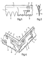
- FIG. 1 shows an exemplary embodiment of a cutting device of the silage cutter according to the invention for cutting cattle feed or the like.
- This cutting device comprises an at least approximately vertically movable up and down support member 1, which supports a knife member 3 designed with teeth 2.
- This knife member 3 is at least approximately horizontally movable back and forth relative to the support member 1.
- the support member 1 has lower retaining teeth 4, which project lower than the knife teeth 2 down.
- the knife member 3 is also preferably arranged on the outside of the support member 1.
- the distance between the tips of the following knife teeth 2 is preferably smaller than the distance between the tips of the following holding teeth 4 of the support member 1, while the height of the knife teeth 2 is smaller than the height of the holding teeth 4 of the support member 1.
- the flanks of the knife teeth 2 form a smaller angle with the connecting line of their tooth tips than the angle enclosed by the flanks of the retaining teeth 4 of the support member 1 with the connecting line of their tooth tips.
- flanks of the knife teeth 2 are straight and form an angle with the connecting line of the tooth tips which is less than 50 ° and preferably less than or equal to 30.
- flanks of the knife teeth 2 can also be curved inwards.
- the retaining teeth 4 of the support member 1 run downwards obliquely in the direction of the knife member 3, while the knife teeth 2 run downwards obliquely in the direction of the support member 1 (FIG. 2).
- the support member 1 is also designed with an upper support edge 5 for the knife member 3, along which the upper edge of the knife member 3 is adjustable to and fro.
- This support edge 5 carries downwardly projecting sealing lips 6, the knife element 3 being enclosed between these sealing lips 6 and the supporting element 1 so that it can move back and forth.
- the support member 1 and the knife member 3 are held against each other by a guide member, which in the embodiment according to FIGS. 1 and 2 consists of one or more slots 7 in the knife member 3, which are passed through by pins protruding from the support member 1. Upwards from the knife member 3, the pins carry a closing plate 7 ', a nut or the like.
- the knife element may carry 3 pins which pass through the slots in the support element 1 in a suitable manner.
- the stroke of the reciprocating oscillating movement of the knife member 3 is generally greater than the distance between the tips of subsequent knife teeth of the knife member 3.
- the support member 1 and the knife member 3 are plate-shaped.
- the knife member 3 can also consist, for example, of a chain with teeth or the like.
- a plate-shaped knife member 3 is preferred because it is easier to lock against an upward adjustment relative to the support member 1.
- the support member 1 can be designed in the form of a profile or box instead of a plate.
- the support member 1 cooperates with only one knife member 3, 5 - 1U
- the support member 1 can also support a further knife member 3 'designed with teeth, which runs parallel to the knife member 3 shown and which is preferably at least approximately horizontally adjustable back and forth relative to the support member 1, wherein the teeth of the knife members 3, 3 'are reciprocally movable back and forth.
- a further knife element 3 ' is shown in FIGS. 5-10, of course several further knife elements 3' can also be used.
- the support member 1 is designed without lower retaining teeth, but as an alternative, retaining teeth 4 can also be used in these embodiments.
- the flanks of the knife teeth of the (each) further knife member 3 ' form a smaller angle with the connecting line of their tooth tips than the angle enclosed by the flanks of the holding teeth with the connecting line of their tooth tips.
- the further Messerogan 3 forms the mirror image of the knife organ 3.
- the two knife members 3 and 3 both support against the upper support edge 5, along which their upper edges are adjustable to and fro.
- This support edge 5 again has downwardly projecting sealing lips 6, the knife elements 3, 3 1 being enclosed between these sealing lips 6 and the supporting element 1 so as to be movable back and forth.
- the support member 1 and the knife members 3, 3 ' are held against each other by pins on the support member 1, the slots 7 pass through the knife members 3, 3'.
- the pins carry a locking plate 7', a nut or the like.
- the flanks of the knife teeth of the (each) knife member 3, 3 ' are straight in the exemplary embodiment according to FIGS. 5-7 and enclose an angle with the connecting line of the tooth tips which is less than 50 ° and preferably less than or equal to 30 ° .
- the embodiment of the cutting device according to FIGS. 8-10 differs only from the embodiment 5 to 7, characterized in that the flanks of the knife teeth of the (each) further knife member 3 'are bent inwards.
- the downward or upward adjustment of the support member 1 can take place continuously, but as an alternative it is also possible that the downward adjustment of the support member 1 is intermittent and the upward adjustment of the support member 1 is continuous.
- the support member 1 can be L-shaped and cooperate with an L-shaped knife member 3 made of flexible material.
- the L-shaped support element 1 interacts with at least one knife set consisting of two knife elements 3 which together form an L-shaped knife member 3.
- the support member 1 is U-shaped (see FIGS. 3 and 11).
- the three knife elements 3, which together form a U-shaped knife element, are coupled to one another and act together with drive elements, which are described in more detail below, and which engage the free ends of the two lateral knife elements 3.
- the adjacent ends of subsequent knife elements 3 are coupled to one another by an at least approximately horizontal chain 8, band or the like, the ends of which are fastened to the relevant knife elements 3 and via a support element 1 in the respective corner supported idler 9 is guided with at least approximately vertical longitudinal axis.
- a conical protective piece 10 runs above and below the guide roller 9.
- the middle leg 1 'of the U-shaped support member 1 runs further upward than the two side legs 1 "in order to prevent loosened crops from falling downward over this side.
- FIG. 4 While the coupling between the adjacent ends of subsequent knife elements 3 is shown in FIG. 4, the coupling between the adjacent ends of subsequent knife elements 3 and knife elements 3 'is shown in FIGS. 7 and 10.
- Two horizontal chains 8, tapes or the like are used, both of which are guided over the guide roller 9.
- the silage cutter 11 shown in FIGS. 3 and 11, on which the cutting device described above is arranged, has a frame 12 which is provided with attachment points 13 for coupling the silage cutter 11 to the lifting device of a tractor.
- the frame 12 comprises an upright frame part 14, behind which a horizontal cross bar 15 extends, to which a plurality of parallel, at least approximately horizontal support tines 16 are fastened.
- the crossbar 15 is rigidly connected to the upright frame part 14 in the embodiment of FIG. 3.
- the U-shaped support member 1, the middle leg 1 ' extends further upwards than the side legs 1 "and which is composed of three metal plates, but can also be designed in profile or box shape, is guided at least approximately vertically up and down by means of guide rollers 17, guide blocks or the like which are mounted in its ends and which are in the Are engaged with U-profiles 18 belonging to the upright frame part 14 of the silage cutter 11.
- the upward and downward adjustment of the U-shaped support member 1 is accomplished with the aid of adjustment members carried by the frame 12.
- these consist of an upright cylinder-piston unit 19 supported by the frame 12, the piston rod 19 'of which carries a disk block 20.
- the support member 1 is adjustable up and down.
- the three knife elements 3, supported by the support member 1, which are connected by the chains 8, bands or the like, which are guided in the corners of the support member 1, which are removed from the upright frame part 14, via the guide rollers 9 (FIG. 4), 3 can be moved back and forth relative to the support member 1 by means of cylinder-piston units 26 which are supported on the support member 1 and which act on the free ends of the two lateral knife elements 3.
- These cylinder-piston units 26, which are double-acting in this exemplary embodiment, are operated via a hydraulic changeover valve and check valves (not shown) in such a way that the piston rods 26 1 of the two cylinder-piston units 26 are always adjusted in the opposite direction, as a result of which the knife elements 3 get a back and forth motion.
- the two double-acting cylinder-piston units 26 are hydraulically coupled to the upstanding cylinder-piston unit 19, which supplies the upward and downward movement of the support element 1.
- the support member 1 is adjusted step by step, each step coinciding with a reciprocating movement of the knife elements 3.
- a silage cutter 11 is shown, in which the upward and downward adjustment of the U-shaped support member 1 is accomplished in a different manner, with the aid of chains 23 or the like acting on the ends of the side legs 1 "of the support member 1
- the lower guide wheels are mounted in the upright frame part 14, while the upper drive wheels are fastened to a drive shaft 24, which is mounted in the upright frame part 14 and which is connected via a drive wheel 25 by means of a chain by a hydraulic motor or
- the top and bottom position of the support member 1 is determined by reversing members (not shown) which can supply the reversal of the direction of rotation of the hydraulic motor.
- the drive means for the reciprocating movement of the knife elements 3 again consist of cylinder-piston units 26 which engage the free ends of the two lateral knife members 3.
- the silage cutter 11 according to FIG. 11 is designed with an upper throwing member 27, with which a block of silage, after it has been transferred to a cattle shed by means of the silage cutter 11 coupled behind a tractor, can be distributed regularly.
- the upper ejector member 27, which is supported by the upright frame part 14, comprises a discharge conveyor 28, which consists of chains (not shown) which can be driven by a drive and which engage at the ends of writing strips 30 provided with pins 29 or the like, which act in the lower part Run of the discharge conveyor 28 can act on the silage.
- the upright frame part 14, instead of U-profiles 18, I-profiles 31, during the cross beam 15 is not rigidly connected to the upstanding frame part 14, but carries guide rollers 32, guide blocks or the like, which are in engagement with the inside of these I-profiles 31.
- These I-profiles 31 are on the outside, in a manner corresponding to the U-profiles 18 in Fig. 3, with the, supported by the free ends of the U-shaped support member 1 guide rollers 17, guide blocks or the like in engagement.
- the up and down adjustment of the crossbar 15 can, for example, in a manner corresponding to the up and down adjustment of the support member 1 of the cutting device, by means of the crossbar 15 coupled, guided by drive wheels, endless chains or the like (not shown) or one in the vertical direction working, carried by the frame 12, cylinder-piston unit (not shown).
- a central, at least approximately horizontal knife 33 with lower cutting teeth interacts with the discharge conveyor 28 and lies at least approximately in the central plane of the transverse beam 15.
- This knife 33 can be driven back and forth in its longitudinal direction by a drive element, such as the cylinder-piston unit 34 shown in FIG. 11, which is supported by the frame 12.
- central knife 33 it is also possible to use a plurality of drivable, parallel, at least approximately horizontal knives with lower cutting teeth that run at a distance from one another.
- the cutting device is in its highest position, just below the discharge conveyor 28 and surrounds the knife 33 and the upper part of the block of silage just below it.
- the upper part of the silage material block resting on these carrying tines 16 is brought into engagement with the knife 33 (the knives) which cut through the upper layer of the silage material (cut through) before the pins 29 of the scrapers 30 of the removal agency rers 28 come into engagement with this.
- the use of the knife 33 (the knife) is particularly important if the silage has a fibrous structure, since the long fibers are cut and divided by the knife 33 (the knife) before being thrown off by the discharge conveyor 28, as a result of which a uniform one Removal of the silage is very required.
- the discharge conveyor 28 is adjustable to and fro in the longitudinal direction of the crossbar 15, the knife 33 (the knives) maintaining its position relative to the frame 12.
- This adjustment option is important, since in a so-called driving silo there are usually two side walls on both sides of the silage pile. If the silage cutter 11 has to cut the first block of silage along one wall, the removal conveyor 28, which is always longer than the width of the block of silage, otherwise the crop cannot be poured over the side edge of the block of silage, into its, away from this wall , Positioned, while when the last block of silage is cut along the opposite wall of the discharge conveyor 28 is adjusted to its other end position.
- the crossbeam 15 can be locked in its lower position relative to the frame 12, which is important when the carrying tines 16 are introduced into the silage.
- a stop for which the crossbar 15 is used in the silage cutter 11 according to FIG. 11, limits the depth of penetration into the silage of the supporting tines 16 fastened to the crossbar 15 such that the upright frame part 14 after the Carrying tines 16 are guided into the silage, still at a distance, for example, about 5 cm, from the silage.
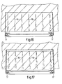
- the corners of the U-shaped support member 1 facing away from the upright frame part 14 are somewhat larger than 90 °, and preferably approximately 94 ° (FIGS. 16 and 17).
- the support member 1 with the knife elements 3 has started the cutting action.
- the carrying tines 16 and / or the frame 12 of the silage cutter 11 are dimensioned such that, under the influence of the cutting force, a deformation of the carrying tines 16 and / or the frame 12 occurs.
- the frame 12 is raised somewhat from the ground under the influence of the cutting force exerted, the carrying tines 16 and possibly the frame 12 being bent.
- Fig. 14 the cutting device has reached its lower position, in which the holding teeth 4 of the support member 1 have come into contact with the ground, while the tips of the knife teeth 2 are a short distance above the ground.
- the cutting device will be adjusted to its uppermost end position and the silage cutter 11 will be lifted (Fig. 15), after which it can be driven by the tractor to the cattle shed.
- the block of silage is gradually moved upwards by the upward adjustment of the crossbeam 15 and the carrying tines 16 (FIG. 15) and brought into engagement with the knife 33 (the knives) and also with the discharge conveyor 28 in order to be regularly discarded .
- the scantling movement can also be accomplished with the help of a special scantling organ.
- silage cutter 11 an embodiment of a silage cutter 11 is shown, in which the ends of the two side legs 1 "of the support member 1 each have an upward extension 36, in which two guide rollers 37 or the like are supported one above the other, in the associated profile 38 of the upright frame part 14 are guided appropriately.
- the lower of the two guide rollers 37 engages on both sides by means of an eccentric 39 on the relevant side leg 111 of the support element 1.
- Each eccentric 39 is connected to an actuating element 40 with which the eccentric 39 can be rotated between two lines drawn in FIG. 18 and positions shown in broken lines, the position of the eccentric 39, as well as the support member 1, shown in solid lines being the working position in which the knife elements, not shown in FIGS. 18 and 19, can perform their cutting action, while those shown in broken lines
- Position the support member 1 is pivoted slightly upwards about the axis of the upper guide rollers 37, as a result of which the support member 1 comes practically free from the cut-out silage block. In this way, after the cutting of a silage block upward adjustment of the support member 1 with the knife elements 3 attached to it can be accomplished particularly easily.
- the adjustment of the control element 40 can take place automatically, simultaneously with the reversal of the adjustment direction of the support element 1.
- the U-shaped support member 1 is only one set of knives, the best Supported by three knife elements 3, it is clear that in combination with it one or more knife sets consisting of three knife elements 3 'can also be used. In this case, the different sets of knives each have their own drive means, such as the cylinder-piston units 26 shown in FIGS. 7 and 10.
Abstract
Description
Silagegutschneider, sowie landwirtschaftliches Gerät versehen mit einem Aufnahmeorgan, das einen dergleichen Silagegutschneider aufweist.Silage cutter, as well as agricultural equipment provided with a receiving member that has such a silage cutter.
Die Erfindung bezieht sich auf einen Silagegutschneider gemäss dem Oberbegriff des Ansprüches 1, sowie auf ein landwirtschaftliches Gerät, versehen mit einem Aufnahmeorgan, das einen dergleichen Silagegutschneider aufweist.The invention relates to a silage cutter according to the preamble of
Ein derartiger Silagegutschneider ist beschrieben in DE-A-3.023.986. Bei diesem bekannten Silagegutschneider dient das Tragorgan nur als Unterstützung für das Messerorgan. Nur das Messerorgan ist dabei für das Schneiden vom Silagegut wirksam. In der Praxis hat es sich gezeigt, dass ein solcher Silagegutschneider keine befriedigende Schneidwirkung hat, was dadurch verursacht wird, dass die Schicht vom Silagegut, in der die Zähne des Messerorganes einragen, ins besondere bei Silagegut mit einer Faserstruktur durch das Messerorgan mitgenommen, jedoch nicht durchgeschnitten werden.Such a silage cutter is described in DE-A-3.023.986. In this known silage cutter, the support member only serves as support for the knife member. Only the knife organ is effective for cutting silage. In practice, it has been shown that such a silage cutter does not have a satisfactory cutting effect, which is caused by the fact that the layer of silage in which the teeth of the knife organ protrude are carried along by the knife organ, particularly in the case of silage with a fiber structure be cut through.
Der Erfindung liegt die Aufgabe zu Grunde einen Silagegutschneider zu schaffen, die schneller und besser als den bekannten Silagegutschneider das Gewächs durchschneiden kann.The invention is based on the object of creating a silage cutter which can cut through the crop faster and better than the known silage cutter.
Diese Aufgabe wird dadurch gelöst, dass das Tragorgan nach unten gerichtete Festhältezähne aufweist, die gleichzeitig mit den Zähnen des Messerorganes auf das Silagegut einwirken können.This object is achieved in that the support member has downward-pointing holding teeth which can act on the silage at the same time as the teeth of the knife member.
In dieser Weise wird erreicht,dass im Betrieb die unteren Festhältezähne des Tragorganes in das Gewächs ragen und die durchzuschneidende Schicht desselben festhalten, während das Messerorgan seine relative, vorzugsweise wenigstens annähernd horizontale hin und hergehende Verstellung relativ zum Tragorgan ausführt, wodurch eine ausgezeichnete Schneidwirkung erhalten wird. Dabei entsteht weiterhin eine besonders glatte und feste Schnittfläche, wodurch weniger Luft in das Gewächs zutreten kann und das Auftreten von Brut, die die Qualität des Gewächses verringert, vorkommen wird. Weiterhin kann dabei eine erhebliche Verringerung der benötigten Antriebsleistung erreicht werden.In this way it is achieved that during operation the lower holding teeth of the support member protrude into the crop and hold the layer to be cut through while the knife member executes its relative, preferably at least approximately horizontal reciprocating adjustment relative to the support member, whereby an excellent cutting effect is obtained . This creates a particularly smooth and firm cut surface, which means that less air can enter the crop and the occurrence of brood, which reduces the quality of the crop, will occur. Furthermore, a significant reduction in the drive power required can be achieved.
Vorzugsweise weist das Tragorgan des erfindungsgemässen Silagegutschneiders Festhaltezähne auf, die tiefer als die Messerzähne abwärts ragen. Dadurch wird eine sehr zweckmässige Festhaltewirkung erzielt.Preferably, the support member of the silage cutter according to the invention has retaining teeth which project downward more than the knife teeth. This provides a very useful retention effect.
Die Erfindung bezieht sich weiterhin auf ein landwirtschaftliches Gerät versehen mit einem Aufnahmeorgan, das dadurch gekennzeichnet ist, dass dieses Aufnahmeorgan einen Silagegutschneider nach der Erfindung aufweist.The invention further relates to an agricultural device provided with a receiving member, which is characterized in that this receiving member has a silage cutter according to the invention.
Die Erfindung wird weiterhin erläutert an Hand der Zeichnung.
- Fig. 1 zeigt einen Teil einer ersten Ausführung einer Schneidvorrichtung des erfindungsgemässen Silagegutschneiders in Vorderansicht.
- Fig. 2 is ein Querschnitt der Schneidvorrichtung nach Fig. 1.
- Fig. 3 ist eine perspektivische Ansicht einer ersten Ausführung eines erfindungsgemässen Silagegutschneiders mit der Schneidvorrichtung nach Fig. l.
- Fig. 4 zeigt perspektivisch ein Eckgebiet der Schneidvorrichtung nach Fig. 3 in grösserem Masstab.
- Fig. 5 zeigt einen Teil einer zweiten Ausführung einer Schneidvorrichtung nach der Erfindung in Vorderansicht.
- Fig. 6 ist ein Querschnitt der Schneidvorrichtung nach Fig. 5.
- Fig. 7 zeigt perspektivisch ein Eckgebiet der Schneidvorrichtung nach Fig. 5 in grösserem Masstab.
- Fig. 8 zeigt einen Teil einer dritten Ausführung Vorderansicht einer Schneidvorrichtung nach der Erfindung in Vorderansicht.
- Fig. 9 ist ein Querschnitt der Schneidvorrichtung nach Fig. 8.
- Fig. 10 zeigt perspektivisch ein Eckgebiet der Schneidvorrichtung nach Fig. 8 in grösserem Masstab.
- Fig. 11 stellt perspektivisch eine etwas geänderte Ausführung des Silagegutschneiders nach Fig. 3 dar, welche mit einem Abwerforgan ausgeführt ist.
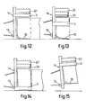
- Fig. 12 - 15 zeigen schematisch verschiedene Stufen beim Ausschneiden eines Silagegutblockes mit dem Silagegutschneider nach Fig. 11.
- Fig. 16 und 17 sind schematische Draufsichten in grösserem Masstab zu Fig. 12 bzw. Fig. 14.
- Fig. 18 ist eine schematische teilweise Seitenansicht des aufstehenden Gestellteiles eines Silagegutschneiders, sowie eines in diesem geführten Tragorganes (dessen Messerelemente fortgelassen sind) in einer Ausführung in welcher dieses Tragorganes eine geringe Verschwenkung erfahren kann.
- Fig. 19 ist ein Querschnitt durch die Ebene XIX-XIX in Fig. 18.
- 1 shows a part of a first embodiment of a cutting device of the silage cutter according to the invention in a front view.
- FIG. 2 is a cross section of the cutting device according to FIG. 1.
- 3 is a perspective view of a first embodiment of a silage cutter according to the invention with the cutting device according to FIG. 1.
- FIG. 4 shows in perspective a corner area of the cutting device according to FIG. 3 on a larger scale.
- Fig. 5 shows part of a second embodiment of a cutting device according to the invention in front view.
- FIG. 6 is a cross section of the cutting device of FIG. 5.
- FIG. 7 shows in perspective a corner area of the cutting device according to FIG. 5 on a larger scale.
- Fig. 8 shows a part of a third embodiment front view of a cutting device according to the invention in front view.
- FIG. 9 is a cross section of the cutting device of FIG. 8.
- 10 shows in perspective a corner area of the cutting device according to FIG. 8 on a larger scale.
- FIG. 11 shows in perspective a somewhat modified version of the silage cutter according to FIG. 3, which is designed with a dropping element.
- FIGS. 12-15 show schematically different stages when cutting out a block of silage with the silage Gutschneider according to Fig. 11.
- 16 and 17 are schematic plan views on a larger scale for FIGS. 12 and 14, respectively.
- 18 is a schematic partial side view of the upstanding part of the frame of a silage cutter, as well as a support member guided therein (the knife elements of which are omitted) in an embodiment in which this support member can experience a slight pivoting.
- FIG. 19 is a cross section through the plane XIX-XIX in FIG. 18.
In Fig. 1 ist ein Ausführungsbeispiel dargestellt einer Schneidvorrichtung des erfindungsgemässen Silagegutschneiders zum Schneiden von Viehfutter oder dergleichem Gewächs.1 shows an exemplary embodiment of a cutting device of the silage cutter according to the invention for cutting cattle feed or the like.
Diese Schneidvorrichting umfasst ein wenigstens annähernd vertikal auf und ab bewegbares Tragorgan 1, das ein mit Zähnen 2 ausgeführtes Messerorgan 3 unterstützt. Dieses Messerorgan 3 ist relativ zum Tragorgan 1 wenigstens annähernd horizontal hin und her bewegbar.This cutting device comprises an at least approximately vertically movable up and down
Das Tragorgan 1 weist untere Festhaltezähne 4 auf,die tiefer als die Messerzähne 2 abwärts ragen.The
Das Messerorgan 3 ist weiterhin vorzugsweise an der Aussenseite des Tragorganes 1 angeordnet.The
Der Abstand zwischen den Spitzen auffolgender Messerzähne 2 ist vorzugsweise kleiner als der Abstand zwischen den Spitzen auffolgender Festhaltezähne 4 des Tragorganes 1, während die Höhe der Messerzähne 2 kleiner ist als die Höhe der Festhaltezähne 4 des Tragorganes 1.The distance between the tips of the following
Wie in Fig. 1 deutlich sichtbar ist, schliessen die Flanken der Messerzähne 2 einen kleineren Winkel mit der Verbindungslinie ihrer Zahnspitzen ein als der durch die Flanken der Festhaltezähnen 4 des Tragorganes 1 mit der Verbindungslinie ihrer Zahnspitzen eingeschlossene Winkel.As is clearly visible in Fig. 1, the flanks of the
Im Ausführungsbeispiel nach den Fig. 1-3 sind die Flanken der Messerzähne 2 gerade und schliessen diese einen Winkel mit der Verbindungslinie der Zahnspitzen ein, der kleiner ist als 50° und vorzugsweise kleiner als oder gleich 30 ist.In the exemplary embodiment according to FIGS. 1-3, the flanks of the
Als Alternative können die Flanken der Messerzähne 2 auch nach innen gebogen sein.As an alternative, the flanks of the
Im Ausführungsbeispiel nach den Fig. 1 und 2 verlaufen die Festhaltezähne 4 des Tragorganes 1 abwärts schräg in Richtung auf das Messerorgan 3 zu, während die Messerzähne 2 abwärts schräg in Richtung auf das Tragorgan l zu verlaufen (Fig. 2).In the exemplary embodiment according to FIGS. 1 and 2, the
Das Tragorgan 1 ist weiterhin mit einem oberen Stützrand 5 für das Messerorgan 3 ausgeführt, entlang welchem der obere Rand des Messerorganes 3 hin und her verstellbar ist.The
Dieser Stützrand 5 trägt abwärts ragende Einschliesslippen 6, wobei das Messerorgan 3 zwischen diesen Einschliesslippen 6 und dem Tragorgan 1 oszillierend hin und her bewegbar eingeschlossen ist.This
Weiterhin werden das Tragorgan 1 und das Messerorgan 3 gegen einander gehalten durch ein Führungsorgan, das in dem Ausführungsbeispiel nach Fig. 1 und 2 besteht aus einem oder mehreren Schlitzen 7 im Messerorgan 3, die durch aus dem Tragorgan 1 ragende Stifte passend durchlaufen werden. Aufwärts vom Messerorgan 3 tragen die Stifte eine Einschliessplatte 7', eine Mutter oder dergleiche.Furthermore, the
Natürlich ist es als Alternative auch möglich,dass das Messerorgan 3 Stifte trägt, die Schlitze im Tragorgan 1 passend durchlaufen.Of course, as an alternative it is also possible for the knife element to carry 3 pins which pass through the slots in the
Der Hub der hin und hergehenden Oszillationsbewegung des Messerorganes 3 ist im allgemeinen grösser als der Abstand zwischen den Spitzen auffolgender Messerzähne des Messerorganes 3.The stroke of the reciprocating oscillating movement of the
Im dargestellten Ausführungsbeispiel sind das Tragorgan 1 und das Messerorgan 3 plattenförmig ausgeführt.In the illustrated embodiment, the
Als Alternative kann das Messerorgan 3 auch beispielsweise aus einer mit Zähnen ausgeführten Kette oder dergleiche bestehen. Ein plattenförmiges Messerorgan 3 wird bevorzugt, da dieses leichter gegen eine aufwärtse Verstellung relativ zum Tragorgan 1 verriegelbar ist.As an alternative, the
Weiter kann das Tragorgan 1 statt plattenförmig, auch profilförmig oder kastenförmig ausgeführt sein.Furthermore, the
Obwohl in der Ausführung nach den Fig. 1 und 2 das Tragorgan 1 mit nur einem Messerorgan 3 zusammenwirkt, kann das Tragorgan 1 auch in der in den Fig. 5 - 1U dargestellten Weise noch ein weiteres mit Zähnen ausgeführtes Messerorgan 3' unterstützen, das parallel zum dargestellten Messerorgan 3 verläuft und das relativ zum Tragorgan 1 vorzugsweise wenigstens ungefähr horizontal hin und her verstellbar ist, wobei die Zähne der Messerorgane 3, 3' gegeneinander oszillierend hin und her bewegbar sind. Obwohl in den Fig. 5 - 10 nur ein weiteres Messerorgan 3' abgebildet ist, können natürlich auch mehrere weitere Messerorgane 3' angewandt werden.Although in the embodiment according to FIGS. 1 and 2 the
In den Ausführungen nach den Fig. 5 - 10 ist das Tragorgan l ohne untere Festhaltezähne ausgeführt, aber als Alternative können auch in diesen Ausführungen wieder Festhaltezähne 4 angewandt werden. In diesem Fall schliessen die Flanken der Messerzähne des (jedes) weiteren Messerorganes 3' einen geringeren Winkel mit der Verbindungslinie ihrer Zahnspitzen ein als der, durch die Flanken der Festhältezähne mit der Verbindungslinie ihrer Zahnspitzen eingeschlossene, Winkel.In the embodiments according to FIGS. 5 to 10, the
Das weitere Messerogan 3' bildet das Spiegelbild des Messerorganes 3.The further Messerogan 3 'forms the mirror image of the
Die beiden Messerorgane 3 und 3' stützen beide gegen den oberen Stützrand 5, entlang welchem ihre oberen Ränder hin und her verstellbar sind. Dieser Stützrand 5 trägt wieder abwärts ragende Einschliesslippen 6, wobei die Messerorgane 3, 31 zwischen diesen Einschliesslippen 6 und dem Tragorgan 1 hin und her bewegbar eingeschlossen sind.The two
Weiter werden das Tragorgan 1 und die Messerorgane 3, 3' gegen einander gehalten durch Stifte am Tragorgan 1, die Schlitze 7 in den Messerorganen 3, 3' durchlaufen. Auswärts vom Messerorgan 3' tragen die Stifte eine Einschliessplatte 7', eine Mutter oder dergleiche.Furthermore, the
Die Flanken der Messerzähne des (jedes) Messerorganes 3, 3' sind im Ausführungsbeispiel nach den Fig. 5 - 7 gerade und schliessen einen Winkel mit der Verbindungslinie der Zahnspitzen ein, der kleiner ist als 50° und vorzugsweise kleiner als oder gleich 30° ist.The flanks of the knife teeth of the (each)
Das Ausführungsbeispiel der Schneidvorrichtung nach den Fig. 8 - 10 unterscheidet sich nur vom Ausführungsbeispiel nach den Fig. 5 - 7, dadurch, dass die Flanken der Messerzähne des (jedes) weiteren Messerorganes 3' nach innen gebogen sind.The embodiment of the cutting device according to FIGS. 8-10 differs only from the
Die Abwärts-, bzw. Aufwärtsverstellung des Tragorganes 1 kann kontinu stattfinden, aber als Alternative ist es gleichfalls möglich, dass die Abwärtsverstellung des Tragorganes 1 intermittierend und die Aufwärtsverstellung des Tragorganes 1 kontinu erfolgt.The downward or upward adjustment of the
Das Tragorgan 1 kann L-förmig sein und mit einem, aus biegsamem Material hergestellten, L-förmigen Messerorgan 3 zusammenwirken.The
In dieser Weise wird es möglich während einer abwärtsen Verstellung des Tragorganes 1 einen Winkel aus dem Viehfutter auszuschneiden.In this way it becomes possible to cut out an angle from the animal feed during a downward adjustment of the
Da das fortlaufend über einen Winkel von etwa 90° Biegen des L-förmigen Messerorganes 3 die Lebensdauer dieses Messerorganes 3 nachteilig beeinflusst, ist es als Alternative dazu auch möglich, dass das L-förmige Tragorgan 1 zusammenwirkt mit wenigstens einem Messersatz bestehend aus zwei Messerelementen 3, die zusammen ein L-förmiges Messerorgan 3 bilden.Since the bending of the L-shaped
Diese zwei zusammen ein L-förmiges Messerorgan bildenden Messerelemente 3 können mit einander gekuppelt sein und mit Antriebsorganen zusammenwirken, die an die freien Enden der beiden Messerelemente 3 angreifen.These two
Obwohl im Vorstehenden nur über ein oder zwei Messerelemente 3 gesprochen ist, die zu dem L-förmigen Tragorgan 1 gehören, ist es deutlich, dass auch in diesem Fall mit jedem Messerelement 3, ein oder mehrere weitere Messerelemente 3', zusammenwirken können in der Weise wie dies in den Fig. 5 - 10 erläutert ist.Although only one or two
Nach einer besonders günstigen Ausführung der Schneidvorrichtung nach der Erfindung ist das Tragorgan 1 U-förmig (siehe die Fig. 3 und 11).According to a particularly favorable embodiment of the cutting device according to the invention, the
Dieses U-förmige Tragorgan 1 mit zwei Seitenschenkeln ltt und einem Mittelschenkel 1' kann zusammenarbeiten mit wenigstens einem aus biegsamen Material hergestellten U-förmigen Messerorgan 3, aber im allgemeinen wird bevorzugt, dass das U-förmige Tragorgan 1 zusammenwirkt mit wenigstens einem Messersatz, bestehend aus drei Messerelementen 3, die zusammen ein U-förmiges Messerorgan bilden.This
In den Fig. 3 und 11 sind die drei, zusammen ein U-förmiges Messerorgan bildenden, Messerelemente 3 mit einander gekuppelt und wirken sie mit im folgenden noch näher beschriebenen Antriebsorganen zusammen, die an die freien Enden der beiden seitlichen Messerelemente 3 angreifen.3 and 11, the three
Wie insbesondere aus Fig. 4 hervorgeht, sind die benachbarten Enden auffolgender Messerelemente 3 miteinander gekuppelt durch eine wenigstens ungefähr horizontale Kette 8, Band oder dergleiche, deren Enden an den betreffenden Messerelementen 3 befestigt sind und die über eine in der betreffenden Ecke durch das Tragorgan 1 unterstützte Leitrolle 9 mit wenigstens ungefähr vertikaler Längsachse geführt ist.As can be seen in particular from FIG. 4, the adjacent ends of
Weiterhin verläuft oberhalb und unterhalb der Leitrolle 9 ein kegelförmiges Schutzstück 10.Furthermore, a conical
Der Mittelschenkel l' des U-förmigen Tragorganes 1 läuft weiter aufwärts durch als die beiden Seitenschenkel 1", um zu verhindern, dass gelockertes Gewächs über diese Seite abwärts fallen würde.The middle leg 1 'of the
Während in Fig. 4 die Kupplung dargestellt ist zwischen den benachbarten Enden auffolgender Messerelemente 3, ist in den Fig. 7 und 10 die Kupplung abgebildet zwischen den benachbarten Enden auffolgender Messerelemente 3 und Messerelemente 3'. Dabei sind zwei horizontale Ketten 8, Bänder oder dergleiche angewandt, die beide über die Leitrolle 9 geführt sind.While the coupling between the adjacent ends of
Die in Fig. 3 und 11 dargesteltten Silagegutschneider 11, an welchen die im Vorstehenden beschriebene Schneidvorrichtung angeordnet ist, weist ein Gestell 12 auf, das mit Anhängepunkten 13 zum Ankupplen des Silagegutschneiders 11 an die Hebevorrichtung eines Schleppers versehen ist.The
Das Gestell 12 umfasst einen aufrechten Gestellteil 14, hinter welchem sich ein horizontaler Querbalken 15 erstreckt, an welchem mehrere parallelle, wenigstens ungefähr horizontale Tragzinken 16 befestigt sind. Der Querbalken 15 ist im Ausführungsbeispiel nach Fig. 3 starr mit dem aufrechten Gestellteil 14 verbunden.The
Das U-förmige Tragorgan 1, dessen Mittelschenkel 1' sich weiter aufwärts erstreckt als die Seitenschenkel 1" und das aus drei Metallplatten zusammengesetzt ist, aber auch profilförmig oder kastenförmig ausgeführt sein kann, ist wenigstens ungefähr vertikal auf und ab verstellbar geführt mit Hilfe in seinen Enden gelagerten Führungsrollen 17, Führungsblöcke oder dergleichen, die im Eingriff mit zu dem aufrechten Gestellteil 14 des Silagegutschneiders 11 gehörenden U-Profilen 18 sind.The
Die Aufwärts- und Abwärtsverstellung des U-förmigen Tragorganes 1 wird bewerkstelligt mit Hilfe durch das Gestell 12 getragener Verstellungsorgane. Diese bestehen beim Silagegutschneider 11 nach Fig. 3 aus einer durch das Gestell 12 unterstützten aufrechten Zylinder-Kolbeneinheit 19, deren Kolbenstange 19' einen Scheibenblock 20 trägt. Mittels vier Seile 21, die über den Scheibenblock 20 und über weitere durch das Gestell 12 unterstützte Scheibenblöcke 22 geführt sind und die immer mit einem Ende auf das Gestell 12 und mit dem anderen Ende auf das freie Ende eines der Seitenschenkel 1' des Tragorganes 1 angreifen, ist das Tragorgan 1 auf und ab verstellbar. Wenn die Kolbenstange 19' der Zylinder-Kolbeneinheit 19 mit dem Scheibenblock 20 abwärts verstellt wird, wird das Tragorgan 1 aufwärts bewegt, während umgekehrt, wenn die Kolbenstange 19' der Zylinder-Kolbeneinheit 19 aufwärts verstellt wird, das Tragorgan 1 abwärts bewegt wird.The upward and downward adjustment of the
Die drei, durch das Tragorgan 1 unterstützten, Messerelemente 3, welche durch die Ketten 8, Bänder oder dergleichen verbunden sind, die in den, vom aufrechten Gestellteil 14 entfernten, Ecken des Tragorganes 1 über die Leitrollen 9 geführt sind (Fig. 4), können im Ausführungsbeispiel nach Fig. 3 relativ zum Tragorgan 1 hin und her bewegt werden mittels Zylinder-Kolbeneinheiten 26, die am Tragorgan 1 abgestützt sind und die auf die freien Enden der beiden seitlichen Messerelemente 3 angreifen. Diese Zylinder-Kolbeneinheiten 26, die in diesem Ausführungsbeispiel doppelwirkend ausgeführt sind, werden über ein hydraulisches Umschaltventil und Rückschlagventile (nicht dargestellt) derart betätigt, dass die Kolbenstangen 261 der beiden Zylinder-Kolbeneinheiten 26 immer in entgegengesetzter Richtung verstellt werden, wodurch die Messerelemente 3 eine hin und hergehende Bewegung erhalten.The three
Die beiden doppelwirkenden Zylinder-Kolbeneinheiten 26 sind hydraulisch gekuppelt mit der aufstehenden Zylinder- <olbeneinheit 19, die die Aufwärts- und Abwärtsbewegung des rragorganes 1 versorgt. Das Tragorgan 1 wird dabei schrittweise verstellt, wobei jeder Schritt mit einer hin bzw. hergehenden Bewegung der Messerelemente 3 zusammenfällt.The two double-acting cylinder-
In Fig. 11 ist ein Silagegutschneider 11 dargestellt, bei welchem die Aufwärts- und Abwärtsverstellung des U-förmigen Tragorganes 1 in anderer Weise bewerkstelligt wird und zwar mit Hilfe von auf den Enden der Seitenschenkel 1" des Tragorganes 1 angreifenden Ketten 23 oder dergleichen, die über obere Antriebsräder und untere Umlenkräder geführt sind. Die unteren Umlenkräder sind im aufrechten Gestellteil 14 gelagert, während die oberen Antriebsräder auf einer Antriebswelle 24 befestigt sind, die im aufrechten Gestellteil 14 gelagert ist und die über ein Antriebsrad 25 mittels einer Kette durch einen Hydromotor oder dergleiche (nicht dargestellt) mit umkehrbarer Drehrichtung antreibbar ist. Dabei wird die oberste und unterste Stellung des Tragorganes 1 durch Umkehrorgane (nicht dargestellt) bestimmt, welche die Umkehrung der Drehrichtung des Hydromotors versorgen können.In Fig. 11, a
In Fig. 11 bestehen die Antriebsmittel für die hin und hergehende Bewegung der Messerelemente 3 wieder aus Zylinder-Kolbeneinheiten 26, die an die freien Enden der beiden seitlichen Messerorgane 3 angreifen.In Fig. 11, the drive means for the reciprocating movement of the
Der Silagegutschneider 11 nach Fig. 11 ist ausgebildet mit einem oberen Abwerforgan 27, mit welchem ein Silagegutblock, nachdem dieser mittels des hinter einem Schlepper gekuppelten Silagegutschneiders 11 nach einem Viehstall übergebracht ist, regelmässig verteilt abgegeben werden kann.The
Das obere Abwerforgan 27, das durch den aufrechten Gestellteil 14 unterstützt ist, umfasst einen Abfuhrförderer 28, der besteht aus durch einen Antrieb (nicht dargestellt) antreibbaren Ketten, die an den Enden von mit Stiften 29 oder dergleichen versehenen Schrableisten 30 angreifen, welche im unterem Trum des Abfuhrförderers 28 auf das Silagegut einwirken können.The
In dieser Ausführung umfasst der aufrechten Gestellteil 14, statt U-Profile 18, I-Profile 31, während der Querbalken 15 nicht starr mit dem aufstehenden Gestellteil 14 verbunden ist, aber Führungsrollen 32, Führungsblöcke oder dergleiche trägt, die im Eingriff mit der Innenseite dieser I-Profile 31 sind. Diese I-Profile 31 sind auf der Aussenseite, in entsprechender Weise wie die U-Profile 18 in Fig. 3, mit den, durch die freien Enden des U-förmigen Tragorganes 1 unterstützten Führungsrollen 17, Führungsblöcke oder dergleiche im Eingriff.In this embodiment, the
Die auf und abgehende Verstellung des Querbalkens 15 kann beispielsweise, in entsprechender Weise wie die auf und abgehende Verstellung des Tragorganes 1 der Schneidvorrichtung, mittels mit dem Querbalken 15 gekuppelter, über Antriebsräder geführter, endloser Ketten oder dergleiche (nicht dargestellt) oder einer in vertikaler Richtung arbeitenden, durch das Gestell 12 getragenen, Zylinder-Kolbeneinheit (nicht dargestellt) realisiert werden.The up and down adjustment of the
Mit dem Abfuhrförderer 28 wirkt ein zentrales, wenigstens ungefähr horizontales Messer 33 mit unteren Schneidzähnen zusammen, das wenigstens ungefähr in der Mittellotebene des Querbalkens 15 liegt. Dieses Messer 33 ist in seiner Längsrichtung hin und her antreibbar durch ein Antriebsorgan, wie die in Fig.· 11 dargestellte Zylinder-Kolbeneinheit 34, die durch das Gestell 12 unterstützt wird.A central, at least approximately
Als Alternative für das zentrale Messer 33 können auch mehrere, im Abstand neben einander verlaufenden, antreibbaren, parallellen, wenigstens ungefähr horizontalen, Messer mit unteren Schneidzähnen benutzt werden.As an alternative to the
Wenn ein Silagegutblock im Viehstall, stützend auf dem Silagegutschneider 11, verteilt werden muss, befindet die Schneidvorrichtung sich in ihrer höchsten Stellung, gerade unter dem Abfuhrförderer 28 und umgibt dort das Messer 33 und den, gerade darunten liegenden, oberen Teil des Silagegutblockes.If a block of silage has to be distributed in the cattle shed, supporting on the
Durch das intermittierend oder kontinu aufwärts Bewegen des Querbalkens 15 mit den Tragzinken 16, wird der obere Teil des, auf diesen Tragzinken 16 ruhenden, Silagegutblockes im Eingriff mit dem Messer 33 (den Messern) gebracht, das (die) die obere Schicht des Silagegutes durchschneidet (durchschneiden), bevor die Stifte 29 der Schraborgane 30 des Abfuhrförderers 28 mit dieser im Eingriff kommen.By intermittently or continuously moving the
Die Anwendung des Messers 33 (der Messer) ist besonders von grosser Bedeutung, wenn das Silagegut eine Faserstruktur aufweist, da die langen Fasern, vor dem Abwerfen durch den Abfuhrförderer 28 durch das Messer 33 (die Messer) durchgeschnitten und unterteilt werden, wodurch eine gleichmässige Abfuhr des Silagegutes sehr gefordert wird.The use of the knife 33 (the knife) is particularly important if the silage has a fibrous structure, since the long fibers are cut and divided by the knife 33 (the knife) before being thrown off by the
Der Abfuhrförderer 28 ist in der Längsrichtung des Querbalkens 15 hin und her verstellbar, wobei das Messer 33 (die Messer) seine (ihre) Stellung relativ zum Gestell 12 behält (behalten).The
Diese Verstellmöglichkeit ist von Bedeutung, da bei einem sogenannten Fahrsilo meistens zwei Seitenwände auf beiden Seiten des Silageguthaufens verlaufen. Wenn der Silagegutschneider 11 entlang der einen Wand den ersten Silagegutblock schneiden muss, wird der Abfuhrförderer 28, der immer länger ist als die Breite des Silagegutblockes, da sonst das Gewächs nicht über den Seitenrand des Silagegutblockes geschüttet werden kann, in seine, von dieser Wand entfernte, Stellung gebracht, während beim Schneiden des letzten Silagegutblockes entlang der gegenüberliegenden Wand der Abfuhrförderer 28 nach seiner anderen Endstellung verstellt wird.This adjustment option is important, since in a so-called driving silo there are usually two side walls on both sides of the silage pile. If the
Der Querbalken 15 kann in seiner unteren Stellung relativ zum Gestell 12 riegelbar sein, was von Bedeutung ist beim Einfuhren der Tragzinken 16 in das Silagegut.The
Um zu erreichen, dass ein ausgeschnittener Silagegutblock und das Tragorgan 1 in besonders einfacher Weise relativ zu einander aufwärts bewegt werden können, ohne dass dabei ein Verkrümmeln des Silagegutes auftritt, ist es natürlich von Bedeutung, dass einiger Spiel zwischen diesem Silagegutblock und dem Tragorgan 1 vorhanden ist.In order to ensure that a cut-out block of silage and the supporting
Dies wird nach der Erfindung dadurch erreicht, dass ein Anschlag, wozu beim Silagegutschneider 11 nach Fig. 11 der Querbalken 15 dient, die Eindringtiefe in das Silagegut der, am Querbalken 15 befestigten, Tragzinken 16 derart beschränkt, dass der aufrechte Gestellteil 14, nachdem die Tragzinken 16 in das Silagegut geführt sind, noch in einigem Abstand, beispielsweise, etwa 5 cm, vom Silagegut entfernt bleibt.This is achieved according to the invention in that a stop, for which the
Dazu ist es weiterhin von Vorteil, wenn die, vom aufrechten Gestellteil 14 abgekehrten Ecken des U-förmigen Tragorganes 1 etwas grösser als 90°,und vorzugsweise etwa 94°, sind (Fig. 16 und 17).For this purpose, it is also advantageous if the corners of the
Die Wirkung des Silagegutschneiders nach Fig. 11 ist schematisch erläutert in den Fig. 12 - 15.The effect of the silage cutter according to FIG. 11 is explained schematically in FIGS. 12-15.
In Fig. 12 sind die Tragzinken 16 über den Boden in das Silagegut gestochen. Das Tragorgan 1 mit den Messerelementen 3 befinden sich noch in der höchsten Stellung gerade unter dem Abwerforgan 27.In Fig. 12, the carrying
In Fig. 13 hat das Tragorgan 1 mit den Messerelementen 3 die Schneidwirkung angefangen. Die Tragzinken 16 und/oder das Gestell 12 des Silagegutschneiders 11 sind derart dimensioniert, dass dabei, unter dem Einfluss der Schneidkraft, eine Verformung der Tragzinken 16 und/oder des Gestelles 12 auftritt. In Fig. 13 ist das Gestell 12, unter dem Einfluss der ausgeübten Schneidkraft, etwas von dem Boden geheben, wobei die Tragzinken 16 und gegebenenfalls das Gestell 12 durchgebogen sind.In Fig. 13, the
In Fig. 14 hat die Schneidvorrichtung ihre untere Stellung erreicht, in welcher die Festhältezähne 4 des Tragorganes 1 mit dem Boden in Berührung gekommen sind, während die Spitzen der Messerzähne 2 einen geringen Abstand über dem Boden liegen.In Fig. 14, the cutting device has reached its lower position, in which the holding
Da die Schneidkraft aufgehoben ist, werden die Tragzinken 16 (und gegebenenfalls das Gestell 12) rückfedern, wodurch das Silagegutblock auf der Oberseite automatisch zum aufrechten Gestellteil 14 hin gekantelt wird.Since the cutting force is released, the carrying tines 16 (and possibly the frame 12) spring back, whereby the block of silage material on the upper side is automatically tilted towards the
Hiernach wird die Schneidvorrichtung nach ihrer obersten Endlage verstellt werden und der Silagegutschneider 11 gehoben werden (Fig. 15), wonach dieser durch den Schlepper nach dem Viehstall gefahren werden kann. Im Viehstall wird der Silagegutblock, durch die aufwärtse Verstellung des Querbalkens 15 und der Tragzinken 16 allmählich aufwärts bewegt (Fig. 15) und mit dem Messer 33 (den Messern) und weiterhin mit dem Abfuhrförderer 28 im Eingriff gebracht, um regelmässig verteilt abgeworfen zu werden. Natürlich kann die Kantelbewegung auch mit Hilfe eines speziellen Kantelorganes bewerkstelligt werden.Then the cutting device will be adjusted to its uppermost end position and the
Es ist möglich, wenigstens auf den Mittelschenkel 1' des U-förmigen Tragorganes 1 an der, zum aufrechten Gestellteil gekehrten Seite ein Wandteil 35 anzuordnen, der schräg von den aufstehenden Gestellteil 14 ab und wieder schräg auf diesem aufstehenden Gestellteil 14 zu verlauft. Dieser Wandteil 35 sorgt dafür, dass bei der Aufwärtsverstellung des U- förmigen Tragorganes 1, dieses Tragorgan 1 einen minimalen Widerstand des Silagegutes erfährt, und dass eine Kantelbewegung des ausgeschnittenen Silagegutblockes auf den aufstehenden Gestellteil 14 zu verursacht werden kann (Fig. 2).It is possible to arrange at least on the middle leg 1 'of the
In den Fig. 18 und 19 ist eine Ausführung eines Silagegutschneiders 11 dargestellt, bei dem die Enden der beiden Seitenschenkel 1" des Tragorganes 1 je eine aufwärtse Verlängerung 36 aufweisen, in welcher zwei Führungsrollen 37 oder dergleiche über einander unterstützt sind, die im zugehörigen Profil 38 des aufrechten Gestellteiles 14 passend geführt sind.18 and 19, an embodiment of a
Auf beiden Seiten greift die untere der beiden Führungsrollen 37 mittels eines Exzenters 39 an den betreffenden Seitenschenkel 111 des Tragorganes 1 an.Jeder Exzenter 39 ist verbunden mit einem Betätigungsorgan 40, mit welchem der Exzenter 39 drehbar ist zwischen zwei in Fig. 18 in gezogenen Linien und in Strichlinien dargestellten Stellungen, wobei die in gezogenen Linien dargestellte Stellung des Exzenters 39, sowie des Tragorganes 1 die Arbeitslage ist, in welcher die in den Fig. 18 und 19 nicht dargestellten Messerelemente ihre schneidende Wirkung ausführen können, während in der in Strichlinien dargestellten Stellung das Tragorgan 1 um die Achse der oberen Führungsrollen 37 etwas aufwärts geschwenkt ist, wodurch das Tragorgan 1 praktisch frei vom ausgeschnittenen Silageblock kommt. In dieser Weise kann das nach dem Ausschneiden eines Silageblockes aufwärts Verstellen des Tragorganes 1 mit den daran befestigten Messerelementen 3 besonders leicht bewerkstelligt werden. Das Verstellen des Bedienungsorganes 40 kann automatisch, gleichzeitig mit dem Umkehren der Verstellungsrichtung des Tragorganes 1, stattfinden.The lower of the two
Obwohl in den Ausführungsbeispielen nach den Fig. 3 und 11 das U-förmige Tragorgan 1 nur einen Messersatz, bestehend aus drei Messerelementen 3, unterstützt, ist es deutlich, dass in Kombination damit auch ein oder mehrere Messersätze, bestehend aus drei Messerelementen 3', benutzt werden önnen. In diesem Fall erhalten die verschiedenen Messersätze je eigene Antriebsmittel, wie die Zylinder-Kolbeneinheiten 26,die in den Fig. 7 und 10 dargestellt sind.Although in the exemplary embodiments according to FIGS. 3 and 11 the
Die Erfindung ist nicht beschränkt auf die in der Zeichnung dargestellten Ausführungsbeispiele, die in verschiedenen Weisen im Rahmen der Erfindung abgeändert werden können.The invention is not limited to the exemplary embodiments shown in the drawing, which can be modified in various ways within the scope of the invention.
Es ist zum Beispiel möglich, auch andere landwirtschaftliche Geräte für Viehfuttergewächs, wie beispielsweise einen Aufnahmewagen, eine Aufnahmepresse oder dergleiche, zu versehen mit einem Aufnahmeorgan, das einem Silagegutschneider nach der Erfindung aufweist.For example, it is also possible to provide other agricultural implements for animal feed crops, such as, for example, a receiving wagon, a receiving press or the like, with a receiving member which has a silage cutter according to the invention.
Claims (15)
Priority Applications (2)
| Application Number | Priority Date | Filing Date | Title |
|---|---|---|---|
| AT84201442T ATE40258T1 (en) | 1982-09-03 | 1982-09-03 | SILAGE CUTTER AND AGRICULTURAL IMPLEMENT EQUIPPED WITH A COLLECTION BODY HAVING SUCH A SILAGE CUTTER. |
| EP84201442A EP0140433B2 (en) | 1982-09-03 | 1982-09-03 | Silage cutter and an agricultural machine having a loader implement including a similar silage cutter |
Applications Claiming Priority (1)
| Application Number | Priority Date | Filing Date | Title |
|---|---|---|---|
| EP84201442A EP0140433B2 (en) | 1982-09-03 | 1982-09-03 | Silage cutter and an agricultural machine having a loader implement including a similar silage cutter |
Related Parent Applications (1)
| Application Number | Title | Priority Date | Filing Date |
|---|---|---|---|
| EP82810368.9 Division | 1982-09-03 |
Publications (4)
| Publication Number | Publication Date |
|---|---|
| EP0140433A2 true EP0140433A2 (en) | 1985-05-08 |
| EP0140433A3 EP0140433A3 (en) | 1985-06-19 |
| EP0140433B1 EP0140433B1 (en) | 1989-01-25 |
| EP0140433B2 EP0140433B2 (en) | 1992-02-05 |
Family
ID=8192485
Family Applications (1)
| Application Number | Title | Priority Date | Filing Date |
|---|---|---|---|
| EP84201442A Expired - Lifetime EP0140433B2 (en) | 1982-09-03 | 1982-09-03 | Silage cutter and an agricultural machine having a loader implement including a similar silage cutter |
Country Status (2)
| Country | Link |
|---|---|
| EP (1) | EP0140433B2 (en) |
| AT (1) | ATE40258T1 (en) |
Cited By (6)
| Publication number | Priority date | Publication date | Assignee | Title |
|---|---|---|---|---|
| FR2591420A1 (en) * | 1985-12-18 | 1987-06-19 | Audureau Sa | Silo-emptying machine with a claw |
| EP0264157A1 (en) * | 1986-10-16 | 1988-04-20 | C. van der Lely N.V. | An implement for cutting fodder, such as silage |
| DE3636775A1 (en) * | 1986-10-29 | 1988-05-05 | Strautmann & Soehne | Flat-silo extraction appliance |
| DE3811924A1 (en) * | 1988-04-09 | 1989-10-19 | Hans Von Der Heide | SILAGE CUTTER WITH U-SHAPED SUPPORT FRAME |
| US5297021A (en) * | 1992-11-16 | 1994-03-22 | Koerlin James M | Zero shear recliner/tilt wheelchair seat |
| DE3644896C3 (en) * | 1986-01-16 | 1999-06-10 | Lengerich Maschf | Device for removing silage |
Citations (1)
| Publication number | Priority date | Publication date | Assignee | Title |
|---|---|---|---|---|
| DE3023986A1 (en) | 1980-06-26 | 1982-01-14 | Heinrich 3013 Barsinghausen Bleinroth | Tractor-mounted silage-extraction implement - has horizontally reciprocating knives with shoes working against frame member undersides |
Family Cites Families (5)
| Publication number | Priority date | Publication date | Assignee | Title |
|---|---|---|---|---|
| US3741051A (en) * | 1971-05-26 | 1973-06-26 | Hesston Corp | Stack feeding method and apparatus |
| DE2138186C3 (en) * | 1971-07-30 | 1974-09-12 | Fa. Heinrich Schaeffer, 4782 Erwitte | Device for mechanical cutting and transport of silage |
| FR2323608A1 (en) * | 1975-09-12 | 1977-04-08 | Sudrie Jean | Silage block removal machine - has toothed chain running in vertically movable rectangular frame cooperating with row of long tines |
| DE2752234A1 (en) * | 1977-11-23 | 1979-06-07 | Bosch Gmbh Robert | HEDGE SHEARS |
| DE3272251D1 (en) * | 1982-04-01 | 1986-09-04 | Trioliet Mullos | Cutting unit for cutting silage |
-
1982
- 1982-09-03 EP EP84201442A patent/EP0140433B2/en not_active Expired - Lifetime
- 1982-09-03 AT AT84201442T patent/ATE40258T1/en not_active IP Right Cessation
Patent Citations (1)
| Publication number | Priority date | Publication date | Assignee | Title |
|---|---|---|---|---|
| DE3023986A1 (en) | 1980-06-26 | 1982-01-14 | Heinrich 3013 Barsinghausen Bleinroth | Tractor-mounted silage-extraction implement - has horizontally reciprocating knives with shoes working against frame member undersides |
Cited By (10)
| Publication number | Priority date | Publication date | Assignee | Title |
|---|---|---|---|---|
| FR2591420A1 (en) * | 1985-12-18 | 1987-06-19 | Audureau Sa | Silo-emptying machine with a claw |
| DE3644896C3 (en) * | 1986-01-16 | 1999-06-10 | Lengerich Maschf | Device for removing silage |
| EP0264157A1 (en) * | 1986-10-16 | 1988-04-20 | C. van der Lely N.V. | An implement for cutting fodder, such as silage |
| EP0399627A2 (en) * | 1986-10-16 | 1990-11-28 | C. van der Lely N.V. | An implement for cutting fodder such as silage |
| EP0399627A3 (en) * | 1986-10-16 | 1990-12-19 | C. Van Der Lely N.V. | An implement for cutting fodder such as silage |
| EP0491681A2 (en) * | 1986-10-16 | 1992-06-24 | C. van der Lely N.V. | An implement for cutting fodder, such as silage |
| EP0491681A3 (en) * | 1986-10-16 | 1992-08-12 | C. van der Lely N.V. | An implement for cutting fodder, such as silage |
| DE3636775A1 (en) * | 1986-10-29 | 1988-05-05 | Strautmann & Soehne | Flat-silo extraction appliance |
| DE3811924A1 (en) * | 1988-04-09 | 1989-10-19 | Hans Von Der Heide | SILAGE CUTTER WITH U-SHAPED SUPPORT FRAME |
| US5297021A (en) * | 1992-11-16 | 1994-03-22 | Koerlin James M | Zero shear recliner/tilt wheelchair seat |
Also Published As
| Publication number | Publication date |
|---|---|
| ATE40258T1 (en) | 1989-02-15 |
| EP0140433B1 (en) | 1989-01-25 |
| EP0140433A3 (en) | 1985-06-19 |
| EP0140433B2 (en) | 1992-02-05 |
Similar Documents
| Publication | Publication Date | Title |
|---|---|---|
| EP0102437B2 (en) | Silage cutter and conventional agricultural implement with such silage cutter | |
| DE2138186C3 (en) | Device for mechanical cutting and transport of silage | |
| DE1507384A1 (en) | thresher | |
| EP0923853B1 (en) | Apparatus and method for shredding a block of compacted material,specialy flower mould | |
| EP0140433B1 (en) | Silage cutter and an agricultural machine having a loader implement including a similar silage cutter | |
| DE2205172C2 (en) | Extraction device for driving silos | |
| DE1507286A1 (en) | Haymaking machine | |
| DE7920491U1 (en) | DEVICE FOR REMOVING GARNING FROM DRIVING SILOS | |
| DE1948187C2 (en) | Fodder extractor for silo - has cutter lowered to level of supporting fork to make parting cut | |
| DE2902521C3 (en) | Device for removing feed from a flat silo | |
| DE2131598A1 (en) | Rotary mower | |
| CH648724A5 (en) | DEVICE FOR TILLAGE TREATMENT, IN PARTICULAR FOR GARDEN OR PARKING SYSTEMS. | |
| DE8428246U1 (en) | CUTTING DEVICE FOR CUTTING FORAGE OR THE LIKE GROWTH | |
| DE4121328C2 (en) | Transport and discharge device for a feed block | |
| DE3248599C2 (en) | ||
| DE3024057C2 (en) | Silage cutter | |
| AT377412B (en) | CUTTING DEVICE FOR AGRICULTURAL EQUIPMENT, IN PARTICULAR SELF-LOADING TROLLEY | |
| DE202020005354U1 (en) | Tillage implement | |
| DE1632836C (en) | Mobile agricultural machine for processing crops | |
| DE3232284A1 (en) | Appliance for extracting fodder portions from flat or mobile silos | |
| AT368470B (en) | DEVICE FOR REMOVING FEED FROM A FLAT SILO | |
| DE2712204A1 (en) | Implement for removing fodder from silos - has three point linkage or foreloader arm mounted fork with cutter assembly at top of frame | |
| DE3131356A1 (en) | Apparatus, mountable on a mobile working machine, for the treatment of rough soils | |
| DE364174C (en) | Device for the production of shaped panels from the peat pulp using the spray and pulp process | |
| DE3932020A1 (en) | Hedge cutter with circular saw blades - has cutter beam operating in inclined plane for trouble-free operation without blockages |
Legal Events
| Date | Code | Title | Description |
|---|---|---|---|
| PUAI | Public reference made under article 153(3) epc to a published international application that has entered the european phase |
Free format text: ORIGINAL CODE: 0009012 |
|
| PUAL | Search report despatched |
Free format text: ORIGINAL CODE: 0009013 |
|
| AC | Divisional application: reference to earlier application |
Ref document number: 102437 Country of ref document: EP |
|
| AK | Designated contracting states |
Designated state(s): AT BE CH DE FR GB IT LI LU NL SE |
|
| AK | Designated contracting states |
Designated state(s): AT BE CH DE FR GB IT LI LU NL SE |
|
| 17P | Request for examination filed |
Effective date: 19850503 |
|
| RAP1 | Party data changed (applicant data changed or rights of an application transferred) |
Owner name: TRIOLIET MULLOS B.V. |
|
| 17Q | First examination report despatched |
Effective date: 19860530 |
|
| R17C | First examination report despatched (corrected) |
Effective date: 19870202 |
|
| ITF | It: translation for a ep patent filed |
Owner name: SOCIETA' ITALIANA BREVETTI S.P.A. |
|
| GRAA | (expected) grant |
Free format text: ORIGINAL CODE: 0009210 |
|
| AC | Divisional application: reference to earlier application |
Ref document number: 102437 Country of ref document: EP |
|
| AK | Designated contracting states |
Kind code of ref document: B1 Designated state(s): AT BE CH DE FR GB IT LI LU NL SE |
|
| REF | Corresponds to: |
Ref document number: 40258 Country of ref document: AT Date of ref document: 19890215 Kind code of ref document: T |
|
| REF | Corresponds to: |
Ref document number: 3279384 Country of ref document: DE Date of ref document: 19890302 |
|
| GBT | Gb: translation of ep patent filed (gb section 77(6)(a)/1977) | ||
| ET | Fr: translation filed | ||
| PLBI | Opposition filed |
Free format text: ORIGINAL CODE: 0009260 |
|
| 26 | Opposition filed |
Opponent name: EMIL HEGEMANN Effective date: 19891014 |
|
| NLR1 | Nl: opposition has been filed with the epo |
Opponent name: EMIL HEGEMANN |
|
| PGFP | Annual fee paid to national office [announced via postgrant information from national office to epo] |
Ref country code: BE Payment date: 19910916 Year of fee payment: 10 |
|
| PGFP | Annual fee paid to national office [announced via postgrant information from national office to epo] |
Ref country code: LU Payment date: 19911024 Year of fee payment: 10 |
|
| PUAH | Patent maintained in amended form |
Free format text: ORIGINAL CODE: 0009272 |
|
| STAA | Information on the status of an ep patent application or granted ep patent |
Free format text: STATUS: PATENT MAINTAINED AS AMENDED |
|
| 27A | Patent maintained in amended form |
Effective date: 19920205 |
|
| AK | Designated contracting states |
Kind code of ref document: B2 Designated state(s): AT BE CH DE FR GB IT LI LU NL SE |
|
| REG | Reference to a national code |
Ref country code: CH Ref legal event code: AEN |
|
| EPTA | Lu: last paid annual fee | ||
| NLR2 | Nl: decision of opposition | ||
| GBTA | Gb: translation of amended ep patent filed (gb section 77(6)(b)/1977) | ||
| NLR3 | Nl: receipt of modified translations in the netherlands language after an opposition procedure | ||
| ET3 | Fr: translation filed ** decision concerning opposition | ||
| PGFP | Annual fee paid to national office [announced via postgrant information from national office to epo] |
Ref country code: CH Payment date: 19920731 Year of fee payment: 11 |
|
| PGFP | Annual fee paid to national office [announced via postgrant information from national office to epo] |
Ref country code: GB Payment date: 19920824 Year of fee payment: 11 |
|
| PG25 | Lapsed in a contracting state [announced via postgrant information from national office to epo] |
Ref country code: LU Free format text: LAPSE BECAUSE OF NON-PAYMENT OF DUE FEES Effective date: 19920903 |
|
| PGFP | Annual fee paid to national office [announced via postgrant information from national office to epo] |
Ref country code: SE Payment date: 19920918 Year of fee payment: 11 |
|
| PG25 | Lapsed in a contracting state [announced via postgrant information from national office to epo] |
Ref country code: BE Effective date: 19920930 |
|
| BERE | Be: lapsed |
Owner name: TRIOLIET MULLOS B.V. Effective date: 19920930 |
|
| PG25 | Lapsed in a contracting state [announced via postgrant information from national office to epo] |
Ref country code: GB Effective date: 19930903 |
|
| PG25 | Lapsed in a contracting state [announced via postgrant information from national office to epo] |
Ref country code: SE Effective date: 19930904 |
|
| PG25 | Lapsed in a contracting state [announced via postgrant information from national office to epo] |
Ref country code: LI Effective date: 19930930 Ref country code: CH Effective date: 19930930 |
|
| GBPC | Gb: european patent ceased through non-payment of renewal fee |
Effective date: 19930903 |
|
| REG | Reference to a national code |
Ref country code: CH Ref legal event code: PL |
|
| EUG | Se: european patent has lapsed |
Ref document number: 84201442.5 Effective date: 19940410 |
|
| PGFP | Annual fee paid to national office [announced via postgrant information from national office to epo] |
Ref country code: FR Payment date: 19980909 Year of fee payment: 17 |
|
| PGFP | Annual fee paid to national office [announced via postgrant information from national office to epo] |
Ref country code: AT Payment date: 19980914 Year of fee payment: 17 |
|
| PG25 | Lapsed in a contracting state [announced via postgrant information from national office to epo] |
Ref country code: AT Free format text: LAPSE BECAUSE OF NON-PAYMENT OF DUE FEES Effective date: 19990903 |
|
| PG25 | Lapsed in a contracting state [announced via postgrant information from national office to epo] |
Ref country code: FR Free format text: LAPSE BECAUSE OF NON-PAYMENT OF DUE FEES Effective date: 20000531 |
|
| REG | Reference to a national code |
Ref country code: FR Ref legal event code: ST |
|
| PGFP | Annual fee paid to national office [announced via postgrant information from national office to epo] |
Ref country code: NL Payment date: 20011129 Year of fee payment: 20 |
|
| PGFP | Annual fee paid to national office [announced via postgrant information from national office to epo] |
Ref country code: DE Payment date: 20011203 Year of fee payment: 20 |
|
| PG25 | Lapsed in a contracting state [announced via postgrant information from national office to epo] |
Ref country code: NL Free format text: LAPSE BECAUSE OF EXPIRATION OF PROTECTION Effective date: 20020903 |
|
| NLV7 | Nl: ceased due to reaching the maximum lifetime of a patent |
Effective date: 20020903 |