EP0141012A2 - Wide dynamic range video camera - Google Patents
Wide dynamic range video camera Download PDFInfo
- Publication number
- EP0141012A2 EP0141012A2 EP84105605A EP84105605A EP0141012A2 EP 0141012 A2 EP0141012 A2 EP 0141012A2 EP 84105605 A EP84105605 A EP 84105605A EP 84105605 A EP84105605 A EP 84105605A EP 0141012 A2 EP0141012 A2 EP 0141012A2
- Authority
- EP
- European Patent Office
- Prior art keywords
- light
- light valve
- input
- pattern
- liquid crystal
- Prior art date
- Legal status (The legal status is an assumption and is not a legal conclusion. Google has not performed a legal analysis and makes no representation as to the accuracy of the status listed.)
- Granted
Links
Images
Classifications
-
- H—ELECTRICITY
- H04—ELECTRIC COMMUNICATION TECHNIQUE
- H04N—PICTORIAL COMMUNICATION, e.g. TELEVISION
- H04N23/00—Cameras or camera modules comprising electronic image sensors; Control thereof
- H04N23/70—Circuitry for compensating brightness variation in the scene
- H04N23/75—Circuitry for compensating brightness variation in the scene by influencing optical camera components
-
- G—PHYSICS
- G02—OPTICS
- G02F—OPTICAL DEVICES OR ARRANGEMENTS FOR THE CONTROL OF LIGHT BY MODIFICATION OF THE OPTICAL PROPERTIES OF THE MEDIA OF THE ELEMENTS INVOLVED THEREIN; NON-LINEAR OPTICS; FREQUENCY-CHANGING OF LIGHT; OPTICAL LOGIC ELEMENTS; OPTICAL ANALOGUE/DIGITAL CONVERTERS
- G02F1/00—Devices or arrangements for the control of the intensity, colour, phase, polarisation or direction of light arriving from an independent light source, e.g. switching, gating or modulating; Non-linear optics
- G02F1/01—Devices or arrangements for the control of the intensity, colour, phase, polarisation or direction of light arriving from an independent light source, e.g. switching, gating or modulating; Non-linear optics for the control of the intensity, phase, polarisation or colour
- G02F1/13—Devices or arrangements for the control of the intensity, colour, phase, polarisation or direction of light arriving from an independent light source, e.g. switching, gating or modulating; Non-linear optics for the control of the intensity, phase, polarisation or colour based on liquid crystals, e.g. single liquid crystal display cells
- G02F1/1313—Devices or arrangements for the control of the intensity, colour, phase, polarisation or direction of light arriving from an independent light source, e.g. switching, gating or modulating; Non-linear optics for the control of the intensity, phase, polarisation or colour based on liquid crystals, e.g. single liquid crystal display cells specially adapted for a particular application
Definitions
- This invention relates to television camera sensors capable of viewing scenes having a wide brightness range.
- Prior television sensors such as vidicons, tend to only resolve either bright objects, by attenuation of the light, and thereby obscure dimly illuminated detail, or to allow bright scene areas to saturate the detector in order to observe dimly lit detail.
- the disadvantage of a system having a single sensor tube is that there is a finite dynamic range of brightness values which can be faithfully sensed by the device. Thus in high dynamic range scenes, details of a scene may be lost due to a conventional television camera's lack of intra-scene range.
- a need thus exists for a camera system capable of handling such high dynamic range scenes, for example on spacecraft in an orbital environment. There, it may be necessary to use television sensors which can handle scenes having very bright areas as well as very dimly lighted background areas which must not be attenuated.
- United States Patent No. 4,032,954 to Grinberg et al discloses a photo-activated alternating current liquid crystal light valve which can impose an AC voltage on a liquid crystal layer in direct relationship, both spatially and temporally, to the variations of intensity of an incident input image; however, this reference does not combine the liquid crystal light valve with a wide dynamic range video camera and selectively attenuate independent areas of a scene to fit bright objects within the dynamic range of the system.
- a third prior art patent United States Patent No. 4,227,201 to Grinberg et al, discloses interface means for coupling CCD signals to a liquid crystal; however, this reference does not disclose a wide dynamic range video camera employing a liquid crystal light valve to selectively attenuate areas of a viewed scene.
- the object of this invention is to go beyond the teachings of the Grinberg et al patents mentioned above, and produce a television camera sensing device which will selectively attenuate bright objects to fit within the sensor's dynamic range while dim images within the viewing scene are not attenuated.
- the present invention is an apparatus employing a liquid crystal cell as an optical/electronic automatic gain control feedback mechanism for selectively attenuating areas of a scene viewed by a television camera so that bright objects are attenuated to fit within the dynamic range of the system, while dim objects are not attenuated.
- the apparatus receives light from an object scene, passes the light through a polarizer and a similarly polarized beamsplitter, and focuses the light on the output plane of the liquid crystal light valve.
- the beamsplitter passes all the light received from the polarizer and splits or reflects in another direction light received back from the light valve.
- the invention may comprise the use of a matrix-addressed transmission mode liquid crystal light valve in a wide dynamic range video camera in order to selectively attenuate bright objects of a scene.
- the wide dynamic range camera system designated generally by numeral 10 operates as illustrated diagrammatically in Figure 1.
- Dotted line 13 represents the case and chassis to which all elements of the camera system 10 are firmly attached.
- Light from an object scene 12 is collected and focused by a lens 14.
- the light is brought to focus at the output plane of the liquid crystal light valve 16, which is connected to drive electronics 32.
- the light passes through the polarizer 18 and the polarization selective beamsplitter 20, and in so doing arrives at the light valve 16 in a linearly polarized state.
- the light valve 16 is oriented such that with no excitation from the cathode ray tube 22 through lens 24, all light is rotated 90° in polarization and reflected perpendicular to its original path due to the polarization selective characteristic of beamsplitter 20.
- the light is converted to an electrical video signal and is amplified by the amplifier 30.
- the electrical signal from amplifier 30 is now utilized to excite the cathode ray tube (CRT) 22 and produce an image on its face which is a duplicate of the image formed at the input face of the seqsor 28.
- the image formed on cathode ray tube 22 is collected and brought to focus by lens 24 upon the input window of liquid crystal light valve 16.
- This light image input has the effect of causing the light valve 16 to rotate the polarization vector of the light, transversing its output section, to undergo a rotation less than the original 90° rotation. Since this effect is proportional to light intensity coming from CRT 22, the overall effect is to selectively attenuate the image pattern focused on the faceplate of sensor 28.
- Bright objects will thus produce a feedback signal through the sensor system and thereby be attenuated.
- This process becomes in effect an optical/electronic automatic gain control feedback mechanism which attempts to maintain the optical signal level arriving at the input of the sensor 28 at a constant level within its own dynamic range.
- the sensor 28 dynamic range operating alone is approximately 200:1.
- the attenuation range of the liquid crystal light valve 16 is approximately 100:1. Therefore, since the system multiplies the range of the sensor and the range of the light valve, the system exhibits a capability for viewing scenes with brightness ranges of 20,000:1 within the same scene.
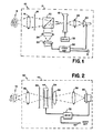
- FIG. 2 illustrates an alternative embodiment of the invention designated generally by numeral 40, in which a reflective-mode, liquid crystal light valve is replaced by a transmission-mode device, the liquid crystal phenomena previously described is implemented with a transparent electrode structure providing the electric fields required.
- This electrode structure is then selected and addressed by a suitable electronic system, CCD registers, etc., and impresses a two-dimensional image pattern on the light valve device 44 which is then able to selectively attenuate areas of the image field of the complete optical system.
- dotted line 43 represents the case and chassis to which all elements of the camera system 40 are firmly attached.
- Light from an object 42 is brought to optical focus at an image plane on light valve 44 by a lens system 46.
- This light passes through a polarizer 48.
- the light valve 44 selectively rotates the plane of polarization of selected areas of the image field in response to the video signal from the video sensor 50 and the drive amplifier 52.
- the light then passes through polarizer 54 and is passed or attenuated by the polarizer 54 in relation to its degree of rotation from its original polarization state.
- Lens 56 serves as a relay field lens for optical efficiency.
- the light is then focused by lens 58 onto sensor 50, which may be a television vidicon detector.
- the signal from sensor 50 is used to feedback a signal to the light valve 44 and to provide an output video signal 60 for external use.
- Liquid crystal light valves are well-known to those skilled in optics, so the details of the light valves used in the two embodiments of the invention are not described herein.
- Such light valves, both the reflective-mode and the transmission-mode types are sold by the Hughes Aircraft Company of Culver Sity, California, U.S.A., and are disclosed in the three patents to Grinberg et al discussed above, and in United States Patents Nos. 3,824,002; 3,976,361 and 4,019,807.
- the inventor has made a television camera system which has the capability of handling a wider range of light intensities within its image field than has been possible in the past.
- the device can handle very bright images having a very dim background within the same scene. This is accomplished in the preferred embodiment by the combination of a liquid crystal light valve with a wide dynamic range video camera and selectively attenuating independent areas of the scene in order to fit bright objects within the dynamic range of the system.
- this camera system produces a theoretical advantage over conventional wide range video camers of about 100:1.
Abstract
Description
- This invention relates to television camera sensors capable of viewing scenes having a wide brightness range.
- Prior television sensors, such as vidicons, tend to only resolve either bright objects, by attenuation of the light, and thereby obscure dimly illuminated detail, or to allow bright scene areas to saturate the detector in order to observe dimly lit detail. The disadvantage of a system having a single sensor tube is that there is a finite dynamic range of brightness values which can be faithfully sensed by the device. Thus in high dynamic range scenes, details of a scene may be lost due to a conventional television camera's lack of intra-scene range. A need thus exists for a camera system capable of handling such high dynamic range scenes, for example on spacecraft in an orbital environment. There, it may be necessary to use television sensors which can handle scenes having very bright areas as well as very dimly lighted background areas which must not be attenuated.
- One prior art sensing device having to do with the intensities of illuminated scenes is United States Patent No. 4,124,278 to Grinberg et al. This patent employs birefringent devices, such as liquid crystal light valves, for generating the subtraction of images; however, this reference does not selectively attenuate bright areas of a viewed scene to fit it within the dynamic range of a sensing device.
- United States Patent No. 4,032,954 to Grinberg et al discloses a photo-activated alternating current liquid crystal light valve which can impose an AC voltage on a liquid crystal layer in direct relationship, both spatially and temporally, to the variations of intensity of an incident input image; however, this reference does not combine the liquid crystal light valve with a wide dynamic range video camera and selectively attenuate independent areas of a scene to fit bright objects within the dynamic range of the system.
- A third prior art patent, United States Patent No. 4,227,201 to Grinberg et al, discloses interface means for coupling CCD signals to a liquid crystal; however, this reference does not disclose a wide dynamic range video camera employing a liquid crystal light valve to selectively attenuate areas of a viewed scene.
- Thus the object of this invention is to go beyond the teachings of the Grinberg et al patents mentioned above, and produce a television camera sensing device which will selectively attenuate bright objects to fit within the sensor's dynamic range while dim images within the viewing scene are not attenuated.
- The present invention is an apparatus employing a liquid crystal cell as an optical/electronic automatic gain control feedback mechanism for selectively attenuating areas of a scene viewed by a television camera so that bright objects are attenuated to fit within the dynamic range of the system, while dim objects are not attenuated. The apparatus receives light from an object scene, passes the light through a polarizer and a similarly polarized beamsplitter, and focuses the light on the output plane of the liquid crystal light valve. The beamsplitter passes all the light received from the polarizer and splits or reflects in another direction light received back from the light valve. In the absence of an input from a CRT, the light reflected back to the beamsplitter from the light valve has its polarization vector rotates 90° by the light valve, and all of the light passes to the video sensor. However, when an input light image from the CRT is impressed upon the input window of the liquid crystal light valve, the amount of rotation of the polarization vector is decreased to an extent depending on light intensity from the CRT. The overall result is to selectively attenuate the image pattern focused on the face plate of the video sensor, bright objects being attenuated more than dimmer ones. This provides an optical/electronic automatic gain control feedback arrangement for maintaining the optical signal level arriving at the input of the video sensor at a level within the desired dynamic range. Alternatively, the invention may comprise the use of a matrix-addressed transmission mode liquid crystal light valve in a wide dynamic range video camera in order to selectively attenuate bright objects of a scene.
-
- Figure 1 is a diagrammatic illustration of an optical system illustrating a preferred embodiment of the invention, and
- Figure 2 is a diagrammatic illustration of an optical system illustrating an alternative embodiment of the invention wherein a reflective mode light valve is replaced by a transmission mode light valve device.
- The wide dynamic range camera system designated generally by
numeral 10 operates as illustrated diagrammatically in Figure 1.Dotted line 13 represents the case and chassis to which all elements of thecamera system 10 are firmly attached. Light from anobject scene 12 is collected and focused by alens 14. The light is brought to focus at the output plane of the liquidcrystal light valve 16, which is connected to driveelectronics 32. The light passes through the polarizer 18 and the polarizationselective beamsplitter 20, and in so doing arrives at thelight valve 16 in a linearly polarized state. Thelight valve 16 is oriented such that with no excitation from thecathode ray tube 22 throughlens 24, all light is rotated 90° in polarization and reflected perpendicular to its original path due to the polarization selective characteristic ofbeamsplitter 20. - It should now be evident that the change in rotation of the polarization vector of the output light effected by the
light valve 16 results in a reduction of the polarized light reflected from thebeamsplitter 20. The reflected light traverses a path throughlens 26 to be focused at the input plane ofvideo sensor 28. - In the
video sensor 28, the light is converted to an electrical video signal and is amplified by theamplifier 30. The electrical signal fromamplifier 30 is now utilized to excite the cathode ray tube (CRT) 22 and produce an image on its face which is a duplicate of the image formed at the input face of theseqsor 28. The image formed oncathode ray tube 22 is collected and brought to focus bylens 24 upon the input window of liquidcrystal light valve 16. This light image input has the effect of causing thelight valve 16 to rotate the polarization vector of the light, transversing its output section, to undergo a rotation less than the original 90° rotation. Since this effect is proportional to light intensity coming fromCRT 22, the overall effect is to selectively attenuate the image pattern focused on the faceplate ofsensor 28. - Bright objects will thus produce a feedback signal through the sensor system and thereby be attenuated. This process becomes in effect an optical/electronic automatic gain control feedback mechanism which attempts to maintain the optical signal level arriving at the input of the
sensor 28 at a constant level within its own dynamic range. Thesensor 28 dynamic range operating alone is approximately 200:1. The attenuation range of the liquidcrystal light valve 16 is approximately 100:1. Therefore, since the system multiplies the range of the sensor and the range of the light valve, the system exhibits a capability for viewing scenes with brightness ranges of 20,000:1 within the same scene. - Figure 2 illustrates an alternative embodiment of the invention designated generally by
numeral 40, in which a reflective-mode, liquid crystal light valve is replaced by a transmission-mode device, the liquid crystal phenomena previously described is implemented with a transparent electrode structure providing the electric fields required. This electrode structure is then selected and addressed by a suitable electronic system, CCD registers, etc., and impresses a two-dimensional image pattern on thelight valve device 44 which is then able to selectively attenuate areas of the image field of the complete optical system. - In Figure 2,
dotted line 43 represents the case and chassis to which all elements of thecamera system 40 are firmly attached. Light from anobject 42 is brought to optical focus at an image plane onlight valve 44 by alens system 46. This light passes through apolarizer 48. Thelight valve 44 selectively rotates the plane of polarization of selected areas of the image field in response to the video signal from thevideo sensor 50 and thedrive amplifier 52. The light then passes throughpolarizer 54 and is passed or attenuated by thepolarizer 54 in relation to its degree of rotation from its original polarization state.Lens 56 serves as a relay field lens for optical efficiency. The light is then focused bylens 58 ontosensor 50, which may be a television vidicon detector. The signal fromsensor 50 is used to feedback a signal to thelight valve 44 and to provide anoutput video signal 60 for external use. - Liquid crystal light valves are well-known to those skilled in optics, so the details of the light valves used in the two embodiments of the invention are not described herein. Such light valves, both the reflective-mode and the transmission-mode types, are sold by the Hughes Aircraft Company of Culver Sity, California, U.S.A., and are disclosed in the three patents to Grinberg et al discussed above, and in United States Patents Nos. 3,824,002; 3,976,361 and 4,019,807.
- From the foregoing it will be apparent that the inventor has made a television camera system which has the capability of handling a wider range of light intensities within its image field than has been possible in the past. The device can handle very bright images having a very dim background within the same scene. This is accomplished in the preferred embodiment by the combination of a liquid crystal light valve with a wide dynamic range video camera and selectively attenuating independent areas of the scene in order to fit bright objects within the dynamic range of the system. Thus, this camera system produces a theoretical advantage over conventional wide range video camers of about 100:1.
Claims (7)
Applications Claiming Priority (2)
| Application Number | Priority Date | Filing Date | Title |
|---|---|---|---|
| US06/530,185 US4546248A (en) | 1983-09-08 | 1983-09-08 | Wide dynamic range video camera |
| US530185 | 1983-09-08 |
Publications (3)
| Publication Number | Publication Date |
|---|---|
| EP0141012A2 true EP0141012A2 (en) | 1985-05-15 |
| EP0141012A3 EP0141012A3 (en) | 1987-08-12 |
| EP0141012B1 EP0141012B1 (en) | 1990-07-18 |
Family
ID=24112754
Family Applications (1)
| Application Number | Title | Priority Date | Filing Date |
|---|---|---|---|
| EP84105605A Expired - Lifetime EP0141012B1 (en) | 1983-09-08 | 1984-05-17 | Wide dynamic range video camera |
Country Status (6)
| Country | Link |
|---|---|
| US (1) | US4546248A (en) |
| EP (1) | EP0141012B1 (en) |
| JP (1) | JPS60121881A (en) |
| AU (1) | AU561088B2 (en) |
| CA (1) | CA1207891A (en) |
| DE (1) | DE3482741D1 (en) |
Cited By (9)
| Publication number | Priority date | Publication date | Assignee | Title |
|---|---|---|---|---|
| FR2604584A1 (en) * | 1986-09-26 | 1988-04-01 | Cornuejols Georges | Device reducing or amplifying luminous contrasts for an audio-visual apparatus for filming, transferring or restoring images or for the human eye |
| FR2626385A1 (en) * | 1988-01-22 | 1989-07-28 | Thomson Csf | SELECTIVE LIGHT SHUTTER, METHOD FOR PRODUCING THE SAME, AND ITS APPLICATION TO AN IMAGE DETECTOR |
| WO1990002464A1 (en) * | 1988-08-23 | 1990-03-08 | Copyguard Enterprises S.A. | Video camera with automatic intensity control |
| EP0390714A1 (en) * | 1989-03-28 | 1990-10-03 | Scanera S.C. | Device for transforming an initial image into a final image with non-linear amplification of point light intensities |
| FR2645284A1 (en) * | 1989-03-28 | 1990-10-05 | Scanera Sc | Photoelectrooptic device for the modulation of radiation and of images |
| US5051770A (en) * | 1986-01-20 | 1991-09-24 | Scanera S.C. | Image processing device for controlling the transfer function of an optical system |
| FR2660447A1 (en) * | 1990-03-28 | 1991-10-04 | Scanera Ste Civile Rech | Optical device for the nonlinear processing of radiation and of images |
| GB2255465A (en) * | 1991-04-30 | 1992-11-04 | Sony Broadcast & Communication | Image capture apparatus with increased dynamic range. |
| WO1994021078A1 (en) * | 1993-03-10 | 1994-09-15 | Gec-Marconi Limited | Optical systems |
Families Citing this family (16)
| Publication number | Priority date | Publication date | Assignee | Title |
|---|---|---|---|---|
| US4860253A (en) * | 1987-06-19 | 1989-08-22 | Hughes Aircraft Company | Associative memory system with spatial light modulator and feedback for adjustable thresholding and enhancement |
| US4961615A (en) * | 1987-06-19 | 1990-10-09 | Hughes Aircraft Company | Associative memory system with spatial light modulator |
| US4837843A (en) * | 1987-06-19 | 1989-06-06 | Hughes Aircraft Company | Hybrid optical and electronic associative memory |
| US4762397A (en) * | 1987-06-19 | 1988-08-09 | Hughes Aircraft Company | Optical phase conjugator with spatially resolvable thresholding utilizing liquid crystal light valve |
| US4825075A (en) * | 1987-07-30 | 1989-04-25 | Lutron Electronics Co., Inc. | Non-electronic gain control |
| US4854677A (en) * | 1987-12-21 | 1989-08-08 | Hughes Aircraft Company | Interferometric/feedback spatial light modulation system and method |
| AU607033B2 (en) * | 1988-01-12 | 1991-02-21 | Sanyo Electric Co., Ltd. | Auto iris/gamma correction apparatus for making automatic exposure adjustment and/or automatic gamma correction in response to video signal and image sensing apparatus comprising such auto iris/gamma correction apparatus |
| US4918534A (en) * | 1988-04-22 | 1990-04-17 | The University Of Chicago | Optical image processing method and system to perform unsharp masking on images detected by an I.I./TV system |
| AU609610B2 (en) * | 1988-05-20 | 1991-05-02 | Sanyo Electric Co., Ltd. | Image sensing apparatus having automatic iris function of automatically adjusting exposure in response to video signal |
| US5046824A (en) * | 1989-02-09 | 1991-09-10 | Hughes Aircraft Company | Adaptive optics system and method |
| US5111301A (en) * | 1989-06-28 | 1992-05-05 | Sanyo Electric Co., Ltd. | Automatic exposure adjusting apparatus for automatically adjusting exposure by fuzzy inference |
| GB2271464A (en) * | 1992-08-21 | 1994-04-13 | Sharp Kk | Photoemission apparatus. |
| US5557324A (en) * | 1992-10-29 | 1996-09-17 | The Johns Hopkins University | Polorization viewer |
| US7663687B2 (en) * | 2004-07-12 | 2010-02-16 | Glenn Neufeld | Variable speed, variable resolution digital cinema camera system |
| US7973838B2 (en) * | 2006-07-07 | 2011-07-05 | Immersive Media Company | Active mask for electronic imaging system |
| US11500231B2 (en) | 2017-08-04 | 2022-11-15 | SMR Patents S.à.r.l. | Systems and methods for modulation control of a camera filter device |
Citations (5)
| Publication number | Priority date | Publication date | Assignee | Title |
|---|---|---|---|---|
| DE2143120A1 (en) * | 1971-08-28 | 1973-03-08 | Bosch Fernsehanlagen | TELEVISION CAMERA |
| DE2355889A1 (en) * | 1972-11-09 | 1974-05-16 | Nat Research Dev Corp London | OPTICAL DEVICE FOR THE INDEPENDENT REGULATION OF THE INTENSITY OF INCIDING LIGHT |
| US4032954A (en) * | 1976-06-01 | 1977-06-28 | Hughes Aircraft Company | Silicon single crystal charge storage diode |
| US4067043A (en) * | 1976-01-21 | 1978-01-03 | The United States Of America As Represented By The Administrator Of The National Aeronautics And Space Administration | Optical conversion method |
| US4124278A (en) * | 1977-06-22 | 1978-11-07 | Hughes Aircraft Company | Optical subtraction of images in real time |
Family Cites Families (2)
| Publication number | Priority date | Publication date | Assignee | Title |
|---|---|---|---|---|
| JPS5917584B2 (en) * | 1978-12-29 | 1984-04-21 | 株式会社富士通ゼネラル | Blooming suppression device in imaging device |
| JPS58134577A (en) * | 1982-02-05 | 1983-08-10 | Nippon Kogaku Kk <Nikon> | Electrooptic optical control element |
-
1983
- 1983-09-08 US US06/530,185 patent/US4546248A/en not_active Expired - Fee Related
-
1984
- 1984-05-17 DE DE8484105605T patent/DE3482741D1/en not_active Expired - Fee Related
- 1984-05-17 EP EP84105605A patent/EP0141012B1/en not_active Expired - Lifetime
- 1984-05-23 CA CA000454974A patent/CA1207891A/en not_active Expired
- 1984-05-24 AU AU28558/84A patent/AU561088B2/en not_active Ceased
- 1984-06-06 JP JP59114703A patent/JPS60121881A/en active Pending
Patent Citations (5)
| Publication number | Priority date | Publication date | Assignee | Title |
|---|---|---|---|---|
| DE2143120A1 (en) * | 1971-08-28 | 1973-03-08 | Bosch Fernsehanlagen | TELEVISION CAMERA |
| DE2355889A1 (en) * | 1972-11-09 | 1974-05-16 | Nat Research Dev Corp London | OPTICAL DEVICE FOR THE INDEPENDENT REGULATION OF THE INTENSITY OF INCIDING LIGHT |
| US4067043A (en) * | 1976-01-21 | 1978-01-03 | The United States Of America As Represented By The Administrator Of The National Aeronautics And Space Administration | Optical conversion method |
| US4032954A (en) * | 1976-06-01 | 1977-06-28 | Hughes Aircraft Company | Silicon single crystal charge storage diode |
| US4124278A (en) * | 1977-06-22 | 1978-11-07 | Hughes Aircraft Company | Optical subtraction of images in real time |
Non-Patent Citations (1)
| Title |
|---|
| INTERNATIONAL BROADCAST ENGINEER, vol. 7, no. 137-138, June-July 1976, pages 18-21, Whitton Press Ltd., Eton, Berks, GB; B.M.SOLTOFF: "Television applications of PLZT ceramics" * |
Cited By (12)
| Publication number | Priority date | Publication date | Assignee | Title |
|---|---|---|---|---|
| US5051770A (en) * | 1986-01-20 | 1991-09-24 | Scanera S.C. | Image processing device for controlling the transfer function of an optical system |
| FR2604584A1 (en) * | 1986-09-26 | 1988-04-01 | Cornuejols Georges | Device reducing or amplifying luminous contrasts for an audio-visual apparatus for filming, transferring or restoring images or for the human eye |
| FR2626385A1 (en) * | 1988-01-22 | 1989-07-28 | Thomson Csf | SELECTIVE LIGHT SHUTTER, METHOD FOR PRODUCING THE SAME, AND ITS APPLICATION TO AN IMAGE DETECTOR |
| EP0326467A1 (en) * | 1988-01-22 | 1989-08-02 | Thomson-Csf | Selective ligt shutter, method of manufacturing it and its use as an image detector |
| WO1990002464A1 (en) * | 1988-08-23 | 1990-03-08 | Copyguard Enterprises S.A. | Video camera with automatic intensity control |
| US5101275A (en) * | 1988-08-23 | 1992-03-31 | Copyguard Enterprises S.A. | Video camera with automatic intensity control |
| EP0390714A1 (en) * | 1989-03-28 | 1990-10-03 | Scanera S.C. | Device for transforming an initial image into a final image with non-linear amplification of point light intensities |
| FR2645284A1 (en) * | 1989-03-28 | 1990-10-05 | Scanera Sc | Photoelectrooptic device for the modulation of radiation and of images |
| FR2660447A1 (en) * | 1990-03-28 | 1991-10-04 | Scanera Ste Civile Rech | Optical device for the nonlinear processing of radiation and of images |
| GB2255465A (en) * | 1991-04-30 | 1992-11-04 | Sony Broadcast & Communication | Image capture apparatus with increased dynamic range. |
| GB2255465B (en) * | 1991-04-30 | 1995-02-01 | Sony Broadcast & Communication | Image capture apparatus |
| WO1994021078A1 (en) * | 1993-03-10 | 1994-09-15 | Gec-Marconi Limited | Optical systems |
Also Published As
| Publication number | Publication date |
|---|---|
| AU561088B2 (en) | 1987-04-30 |
| JPS60121881A (en) | 1985-06-29 |
| EP0141012A3 (en) | 1987-08-12 |
| DE3482741D1 (en) | 1990-08-23 |
| EP0141012B1 (en) | 1990-07-18 |
| US4546248A (en) | 1985-10-08 |
| AU2855884A (en) | 1985-03-14 |
| CA1207891A (en) | 1986-07-15 |
Similar Documents
| Publication | Publication Date | Title |
|---|---|---|
| EP0141012B1 (en) | Wide dynamic range video camera | |
| EP0138398B1 (en) | Thermal imager | |
| US4515443A (en) | Passive optical system for background suppression in starring imagers | |
| US4556986A (en) | Optical stereo video signal processor | |
| EP0075016A1 (en) | Twisted nematic liquid crystal light valve with compensation | |
| EP0075015A1 (en) | Liquid crystal light valve with birefringence compensation | |
| US4647154A (en) | Optical image processor | |
| EP0591903A1 (en) | Phase type spatial light modulator and optical information processor employing the same | |
| FR2610159A1 (en) | IMAGE STABILIZATION DEVICE FOR TRANSPORTABLE VIDEO CAMERA | |
| US5541705A (en) | Camera with large dynamic range | |
| US4511219A (en) | Kalman filter preprocessor | |
| US5101275A (en) | Video camera with automatic intensity control | |
| US4772785A (en) | Dynamic range compression/expansion of light beams by photorefractive crystals | |
| EP0470825B1 (en) | Optical gauging apparatus | |
| EP0376282A2 (en) | Photo-modulation method and system for reproducing charge latent image | |
| Marie | Light valves using dkdp operated near its curie point: Titus and phototitus | |
| US3429641A (en) | Projection system | |
| SE8305065L (en) | DEVICE FOR RECORDING PHOTOGRAPHIC MATERIALS VIEWING ON A VIDEO MONITOR | |
| JP2739085B2 (en) | Information signal processing system using laser | |
| US3754144A (en) | Image converter changing information of one frequency to another frequency | |
| JPH03115816A (en) | Apparatus for calibration on orbit of radiometer | |
| RU1796496C (en) | Antidazzling device | |
| JP2554086Y2 (en) | Bias light circuit for television camera | |
| US3541333A (en) | System for enhancing fine detail in thermal photographs | |
| CRAIG | Wind dynamic range video camera(Patent) |
Legal Events
| Date | Code | Title | Description |
|---|---|---|---|
| PUAI | Public reference made under article 153(3) epc to a published international application that has entered the european phase |
Free format text: ORIGINAL CODE: 0009012 |
|
| AK | Designated contracting states |
Designated state(s): BE CH DE FR GB IT LI NL SE |
|
| PUAL | Search report despatched |
Free format text: ORIGINAL CODE: 0009013 |
|
| AK | Designated contracting states |
Kind code of ref document: A3 Designated state(s): BE CH DE FR GB IT LI NL SE |
|
| 17P | Request for examination filed |
Effective date: 19871103 |
|
| 17Q | First examination report despatched |
Effective date: 19880126 |
|
| GRAA | (expected) grant |
Free format text: ORIGINAL CODE: 0009210 |
|
| AK | Designated contracting states |
Kind code of ref document: B1 Designated state(s): BE CH DE FR GB IT LI NL SE |
|
| PG25 | Lapsed in a contracting state [announced via postgrant information from national office to epo] |
Ref country code: SE Effective date: 19900718 Ref country code: NL Effective date: 19900718 Ref country code: IT Free format text: LAPSE BECAUSE OF FAILURE TO SUBMIT A TRANSLATION OF THE DESCRIPTION OR TO PAY THE FEE WITHIN THE PRESCRIBED TIME-LIMIT;WARNING: LAPSES OF ITALIAN PATENTS WITH EFFECTIVE DATE BEFORE 2007 MAY HAVE OCCURRED AT ANY TIME BEFORE 2007. THE CORRECT EFFECTIVE DATE MAY BE DIFFERENT FROM THE ONE RECORDED. Effective date: 19900718 |
|
| REF | Corresponds to: |
Ref document number: 3482741 Country of ref document: DE Date of ref document: 19900823 |
|
| ET | Fr: translation filed | ||
| NLV1 | Nl: lapsed or annulled due to failure to fulfill the requirements of art. 29p and 29m of the patents act | ||
| PG25 | Lapsed in a contracting state [announced via postgrant information from national office to epo] |
Ref country code: GB Effective date: 19910517 |
|
| PLBE | No opposition filed within time limit |
Free format text: ORIGINAL CODE: 0009261 |
|
| STAA | Information on the status of an ep patent application or granted ep patent |
Free format text: STATUS: NO OPPOSITION FILED WITHIN TIME LIMIT |
|
| PG25 | Lapsed in a contracting state [announced via postgrant information from national office to epo] |
Ref country code: LI Effective date: 19910531 Ref country code: CH Effective date: 19910531 Ref country code: BE Effective date: 19910531 |
|
| 26N | No opposition filed | ||
| BERE | Be: lapsed |
Owner name: NATIONAL AERONAUTICS AND SPACE ADMINISTRATION Effective date: 19910531 |
|
| GBPC | Gb: european patent ceased through non-payment of renewal fee | ||
| PG25 | Lapsed in a contracting state [announced via postgrant information from national office to epo] |
Ref country code: FR Effective date: 19920131 |
|
| REG | Reference to a national code |
Ref country code: CH Ref legal event code: PL |
|
| PG25 | Lapsed in a contracting state [announced via postgrant information from national office to epo] |
Ref country code: DE Effective date: 19920303 |
|
| REG | Reference to a national code |
Ref country code: FR Ref legal event code: ST |