EP0141589A1 - Inflatable uterine hemostat - Google Patents
Inflatable uterine hemostat Download PDFInfo
- Publication number
- EP0141589A1 EP0141589A1 EP84307177A EP84307177A EP0141589A1 EP 0141589 A1 EP0141589 A1 EP 0141589A1 EP 84307177 A EP84307177 A EP 84307177A EP 84307177 A EP84307177 A EP 84307177A EP 0141589 A1 EP0141589 A1 EP 0141589A1
- Authority
- EP
- European Patent Office
- Prior art keywords
- inflatable portion
- intrauterine device
- uterus
- inflatable
- uterine
- Prior art date
- Legal status (The legal status is an assumption and is not a legal conclusion. Google has not performed a legal analysis and makes no representation as to the accuracy of the status listed.)
- Withdrawn
Links
Images

Classifications
-
- A—HUMAN NECESSITIES
- A61—MEDICAL OR VETERINARY SCIENCE; HYGIENE
- A61B—DIAGNOSIS; SURGERY; IDENTIFICATION
- A61B17/00—Surgical instruments, devices or methods, e.g. tourniquets
- A61B17/12—Surgical instruments, devices or methods, e.g. tourniquets for ligaturing or otherwise compressing tubular parts of the body, e.g. blood vessels, umbilical cord
- A61B17/12022—Occluding by internal devices, e.g. balloons or releasable wires
- A61B17/12131—Occluding by internal devices, e.g. balloons or releasable wires characterised by the type of occluding device
- A61B17/12136—Balloons
-
- A—HUMAN NECESSITIES
- A61—MEDICAL OR VETERINARY SCIENCE; HYGIENE
- A61B—DIAGNOSIS; SURGERY; IDENTIFICATION
- A61B17/00—Surgical instruments, devices or methods, e.g. tourniquets
- A61B17/12—Surgical instruments, devices or methods, e.g. tourniquets for ligaturing or otherwise compressing tubular parts of the body, e.g. blood vessels, umbilical cord
- A61B17/12022—Occluding by internal devices, e.g. balloons or releasable wires
- A61B17/12099—Occluding by internal devices, e.g. balloons or releasable wires characterised by the location of the occluder
-
- A—HUMAN NECESSITIES
- A61—MEDICAL OR VETERINARY SCIENCE; HYGIENE
- A61B—DIAGNOSIS; SURGERY; IDENTIFICATION
- A61B17/00—Surgical instruments, devices or methods, e.g. tourniquets
- A61B17/42—Gynaecological or obstetrical instruments or methods
-
- A—HUMAN NECESSITIES
- A61—MEDICAL OR VETERINARY SCIENCE; HYGIENE
- A61B—DIAGNOSIS; SURGERY; IDENTIFICATION
- A61B90/00—Instruments, implements or accessories specially adapted for surgery or diagnosis and not covered by any of the groups A61B1/00 - A61B50/00, e.g. for luxation treatment or for protecting wound edges
- A61B90/39—Markers, e.g. radio-opaque or breast lesions markers
Definitions
- This invention relates to an inflatable medical device designed for intrauterine insertion to control uterine bleeding.
- Uterine bleeding is a commonly encountered clinical condition attributable to a variety of causes, including post-partum hemorrhages following childbirth, post-operative hemorrhages following procedures such as dilation and curettage, and dysfunctional uterine bleeding. Severe uterine bleeding resulting from conditions other than those of the normal menstrual cycle can be a serious problem. For example, about 500 ml. or more of blood is lost in 50% of all childbirths. It can lead to exsanguination, the possibility of peritoneal irritation or infection and other dangerous situations. Hemorrhage is, in fact, one of the major causes of maternal mortality. In one study, maternal death was attributed to hemmorhage in 30% of all maternal deaths. Accordingly, it is desirable to control such bleeding, if possible, at its onset.
- U.S. Patent No. 2,122,579 issued July 15, 1938 to Meckstroth, discloses an intrauterine device having a semirigid non-inflatable head which conforms to the shape of the uterus and an insertion member which acts as a capillary draw. Meckstroth discloses that the purpose of his device is to remove debris from the uterus to relieve amenorrhea and dysmenorrhea. However, no mention is made in the Meckstroth patent of the use of this or any other device to exert pressure on the uterine walls or to control uterine bleeding in any manner.
- This invention relates to an inflatable medical device capable of being easily inserted into the uterine cavity, and capable of controlling uterine bleeding once inserted and inflated.
- This inflatable device may also be adapted to permit accumulated blood or mucosal debris present in the uterus to be drained or aspirated from the uterine cavity.
- a preferred embodiment of the present invention comprises an inflatable portion made of a soft, pliable material such as rubber (latex rubber being preferred), pliable polymeric sheets or relatively heavy gauge films, animal gut or similar materials.
- a soft, pliable material such as rubber (latex rubber being preferred), pliable polymeric sheets or relatively heavy gauge films, animal gut or similar materials.
- some or all of the material comprising this inflatable portion will be radioopaque.
- Radioopaque materials may be used to form the inflatable portion, or may be incorporated into all or selected areas of the inflatable portion. Radioopacity enables easy location of the inflated portion by X-rays and serves as a means for determining the size and shape of the uterus. Any suitable means of imparting radioopacity to the inflatable portion of the device which will not detract from its pliability may be used, including radioopaque particulate fillers, filaments or the like.
- Insertion and proper positioning of the device within the uterine cavity is facilitated by an insertion means, which can be a flexible, semirigid stem or guide, or the like, which is attached to the inflatable portion of the device and surrounded by it.
- This insertion means can be hollow or solid, and can be made of any suitable material that will not damage the inflatable portion of the device, such as rubber, especially latex rubber, semirigid polymeric materials, and the like.
- the device Once the device is inserted and properly positioned in the uterus, its inflatable portion is inflated through a tubular inflation channel, made of any relatively flexible material such as rubber, polymeric materials, and the like, connected to and in communication with the interior of the inflatable portion, using any suitable means, e.g., a fluid such as water, saline solution, air or any other inflating liquid or gas. If a liquid is used to inflate the inflatable portion of the device, it will preferably be of a viscosity such that it will not be difficult to infuse it into or withdraw it from the device.
- a fluid such as water, saline solution, air or any other inflating liquid or gas.
- the inflation channel contains proximally located pores through which the inflatable portion can be inflated and deflated once the device has been inserted into the uterus, and will also be adapted at its lower or distal end by means which permit it to be sealed once the inflatable portion has been inflated and to be unsealed to permit the inflating means, e.g., air or other inflating gas, or a liquid such as water, to be bled from the interior of the inflatable portion of the device.
- inflating means e.g., air or other inflating gas, or a liquid such as water
- the inflation channel can, for example, be provided with a one-way valve at or near its distal end, through which any suitable means for inflating or deflating the inflatable portion of the device -- a hypodermic syringe, a hose or tube connected to a fluid source such as an air pump, etc. -- can be inserted.
- a two way valve, a clamp, plug or stopper, or any other suitable means can be used to seal and unseal the distal end of the inflation channel.
- the shape of the fully inflated inflatable portion of the device will generally conform as closely as possible to the shape of the interior of the uterus.
- the inflatable portion of the device will be generally pear shaped when the device is constructed for insertion into the typical human uterus, and will have a width at its upper or proximal end typically, although not necessarily, of about two inches and a width at its lower or distal end, again typically, although not necessarily, of about one half inch.
- the length of the insertion means will be typically, although not necessarily, about 2 1/2 inches, exclusive of the inflation channel to which it is connected.
- the uterine cavity typically measures approximately 6-8 cm in nulliparous women and approximately 9-10 cm in multiparous women, and the inflatable portion of a device incorporating the present invention configured for use in the human uterus will typically, although not necessarily, have these dimensions when inflated.
- the pear shaped configuration of the inflatable portion of a device constructed in accordance with the present invention for use in the typical human uterus permits it to align, once inflated, with the configuration of the uterine interior.
- the endometrium is relatively thinner after menstruation (typically, it will be about 0.5 mm thick at this time) and relatively thicker during its proliferative phase (after ovulation and during pregnancy, when it will be about 5 mm thick).
- This pear shaped configuration of the inventive device together with the provision of a sheet or film of smooth, pliable material used to form the inflatable portion having a thickness sufficient to exert pressure on the uterine wall, e.g., in the case of a rubber or rubber latex inflatable portion a thickness ranging from about 0.025 mm to about 2 mm, and preferably from about 0.25 mm to about lmm, permits the inflatable portion to expand and contract with the uterus while exerting sufficient pressure on uterine blood vessels to curtail bleeding.
- the inflatable portion of a device constructed in accordance with the present invention for use in the typical human uterus will generally be inflated to a pressure of from about 40 mm of mercury to about 120 mm of mercury, and preferably to a pressure of from about 60 mm of mercury to about 100 mm of mercury.
- Any suitable means e.g., a pressure gauge connected to the inflation channel at its lower or distal end above the means used to seal the inflation channel, can be used to indicate and thus control the extent to which the inflatable portion is inflated.
- the pressure gradient in the uterine cavity decreases from above downwards during labor and other situations involving contractions of the uterus.
- twin apical projections typically although not necessarily of a diameter of about 0.5 cm. when the device is constructed for use in the typical human uterus, designed to conform to and block the entrances to the fallopian tubes, will be appropriately disposed on the inflatable portion of the device at its upper or proximal end. These projections prevent leakage of uterine blood or mucosal debris into the peritoneal area and, as a consequence, help prevent peritoneal irritation or infection.
- accumulated blood or mucosal debris present in the uterus can be removed, if desired, from the uterine cavity by providing a drainage system comprising a second tubular channel, separate from the inflation channel and attached to the outer surface of the wall of the inflatable portion.
- This second or drainage channel which can also be fabricated of rubber, especially latex rubber, polymeric materials and the like, will contain pores or openings at its upper or proximal end, at and above the level of the internal os, through which blood and debris can drain into the second channel and thence out its lower or distal end.
- Suction may be applied to the lower or distal end to aspirate blood and debris, using any suitable vacuum- producing means, e.g., a suction pump.
- Blood and debris can be drained or aspirated through the second channel with the inflatable portion of the device in an inflated or deflated state.
- the inflatable portion once positioned in the uterine cavity and inflated, can be deflated while in place if it becomes difficult to aspirate blood and debris while the inflatable portion is inflated, the blood and debris aspirated by means of the second, separate tubular channel, and the inflatable portion then reinflated by means of the first tubular channel to reexert adequate pressure on the uterine wall.
- the walls of the pores and, if desired, the walls of the second channel itself may be reinforced with extra thicknesses of rubber, latex rubber, polymeric material or the like.
- crisscrossing channels suitably reinforced if desired, may be incorporated to communicate between the pores and from the pores to the second channel to facilitate further the drainage of blood and debris.
- the diameters of the inflation and drainage channels, taken together, can range from about 3 to about 5 mm in a small device, from about 6 to about 8 mm in a medium sized device and from about 8 to about 10 mm in a large device intended for use in the human uterus. If medium or large devices are employed, and if the cervix is not already dilated, dilation of the cervix by known means may be necessary prior to inserting the device.
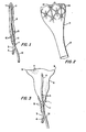
- Figure 1 is a cross sectional view of a device embodying the present invention in an uninflated state, illustrating, among other features, the insertion means, a rubber stem or guide portion used.to position the device in the uterus.
- Figure 2 is an enlarged cross sectional view of the wall of the optional drainage system portion of a device embodying the present invention, illustrating, among other features, pores or openings with reinforced walls and crisscrossing channels communicating between the pores and from them to a drainage channel to facilitate drainage of blood and debris from the uterine cavity.
- Figure 3 is a cross sectional front view of an inflated device embodying the present invention, illustrating, among other features, the conformation of the inflatable portion of the device to the side to side triangular shape of the interior of the human uterus.
- Figure 4 is a cross sectional front view of an inflated device embodying the present invention illustrating the device in place in the human uterus.
- Figure 5 is a cross sectional side view of an inflated device embodying the present invention, illustrating the conformation of the inflatable portion of the device to the flattened front to back shape of the interior of the human uterus.
- the uterus 20 consists of two layers in addition to the thick muscular layer 21, an outer mucosal layer 22 and an inner muscularis mucosal layer 23 underlying the mucosal layer 22 and containing numerous blood vessels 24.
- the uterus 20 also contains openings 25 and 26 from the aqueducts 27 and 28 of the fallopian tubes 29 and 30 located in the upper portion of the uterine cavity 31.
- the entire uterine cavity is flattened from front to back and triangular in shape from side to side.
- the lower part 32 of the uterus 20 is integral with an elongate vagina 33.
- the vagina 33 has a vaginal cavity 34 having an opening or entrance 35.
- the opposite end 36 of the vaginal cavity 34 is in communication with the cervix 37, having a cervical opening 38 providing a passage from the vaginal cavity 34 into the uterine cavity 31.
- a device 1 embodying the present invention has an insertion means in the form of a semirigid flexible rubber stem 2 which facilitates insertion of the device 1 through the cervical opening 38 from the vaginal cavity 34 into the uterine cavity 31.
- the device 1 is inflated through a channel 3 having a seal 4 using any appropriate inflating means such as air or other inflating gas, or a liquid such as water, which passes through the pores 5 to inflate fully the inflatable portion 6 of the device 1.
- the wall of the inflatable portion 6 can contain radioopaque elements, such as the radioopaque particles 7 illustrated in Figure I, which permit the inflatable portion 6 to be easily located by means of X-rays to insure that the device 1 is properly positioned.
- the inflatable portion 6 of the device 1 is comprised of a resilient pliable material of a sufficient thickness to exert pressure, when fully inflated, against both the uterine mucosal layer 22 and the uterine muscularis mucosal layer 23. Thus, pressure is exerted against the blood vessels 24 in the muscularis mucosal layer 23 thereby constricting these vessels and stopping uterine bleeding. As illustrated in Figures 3 and 4, the inflated device 1 conforms to the shape of the uterine cavity and is thus able to exert pressure against all sections of the inner wall of the uterus 20.
- the inflatable portion 6 of the device 1 should, when inserted, pass beyond the cervix 37 into the uterine cavity 31, since any severe dilation of the cervix 37 by inflation of the inflatable portion 6 of the device 1 therein could cause moderate to severe pain.
- the device can also have twin apical projections 8 and 9 which conform to and block the openings 25 and 26 of the aqueducts 27 and 28 of the fallopian tubes 29 and 30.
- This optional blocking feature prevents any uterine blood or debris from entering the peritoneal area. Any uterine blood or debris which has accumulated before bleeding has been stopped can be aspirated through the pores 10 located on the device 1 at its entrance to the lower part of the uterine cavity 32. These pores 10 are part of a drainage system 11 culminating in a channel 12 separate from the channel 3 used to inflate the device 1.
- the pores 10 in the drainage system 11 can have reinforced walls 13 and crisscrossing channels 14 communicating between the pores 10 and from them to the drainage channel 12.
- the walls of the drainage system 11 including, of course, those of the drainage channel 12, can likewise be reinforced.
- Figure 5 illustrates the fact that the inflatable portion 6 of the device 1, when inflated, is relatively flatter from front to back than from top to bottom, i.e., the distance across line 15-15 is less than the distance across line 16-16, in conformity with the flattened (from front to back) shape of the uterine cavity.
- intrauterine device of the present invention While a preferred embodiment of the intrauterine device of the present invention has been described above, it is obvious that changes in structure and method can be made by those skilled in the art, including changes of size, shape and materials of construction to adapt the device for use not only in different size human uteruses but also for veterinary medical use in other mammalian uteruses, such as those of cows, sheep, mares and other valuable animals, without departing from the spirit of the invention as defined in the appended claims.
Abstract
An inflatable intrauterine device to control uterine bleeding, which can also be adapted to permit drainage or aspiration of accumulated blood or mucosal debris from the uterine cavity, is provided.
Description
- This invention relates to an inflatable medical device designed for intrauterine insertion to control uterine bleeding.
- Uterine bleeding is a commonly encountered clinical condition attributable to a variety of causes, including post-partum hemorrhages following childbirth, post-operative hemorrhages following procedures such as dilation and curettage, and dysfunctional uterine bleeding. Severe uterine bleeding resulting from conditions other than those of the normal menstrual cycle can be a serious problem. For example, about 500 ml. or more of blood is lost in 50% of all childbirths. It can lead to exsanguination, the possibility of peritoneal irritation or infection and other dangerous situations. Hemorrhage is, in fact, one of the major causes of maternal mortality. In one study, maternal death was attributed to hemmorhage in 30% of all maternal deaths. Accordingly, it is desirable to control such bleeding, if possible, at its onset.
- Among the various intrauterine devices described in the prior art are those disclosed in U.S. Patents Nos. 3,933,152, issued January 20, 1976 to Moulding; 3,933,153, issued January 20, 1976 to Csatary et al; 3,994,291, issued November 30, 1976 to Salmasian; 3,918,443, issued November 11, 1975 to Vennard and 3,464,409, issued October 21, 1965 to Murphy. Each of these patents discloses inflatable intrauterine devices which conform to the shape of the uterus.
- U.S. reissue Patent No. 29,207, reissued May 10, 1977 to Bolduc et al. and U.S. Patent No. 3,934,580, issued January 27, 1976 to Cournout, disclose intrauterine devices capable of dispensing materials into the uterus or fallopian tubes.
- None of the aforementioned patents disclose the use of any device to withdraw materials from the uterine cavity. Nor are the devices disclosed designed for or useful for controlling uterine bleeding.
- U.S. Patent No. 2,122,579, issued July 15, 1938 to Meckstroth, discloses an intrauterine device having a semirigid non-inflatable head which conforms to the shape of the uterus and an insertion member which acts as a capillary draw. Meckstroth discloses that the purpose of his device is to remove debris from the uterus to relieve amenorrhea and dysmenorrhea. However, no mention is made in the Meckstroth patent of the use of this or any other device to exert pressure on the uterine walls or to control uterine bleeding in any manner.
- This invention relates to an inflatable medical device capable of being easily inserted into the uterine cavity, and capable of controlling uterine bleeding once inserted and inflated.
- This inflatable device may also be adapted to permit accumulated blood or mucosal debris present in the uterus to be drained or aspirated from the uterine cavity.
- Since the uterus is an organ composed of smooth muscle and therefore susceptible to damage from a rigid intrauterine device, a preferred embodiment of the present invention comprises an inflatable portion made of a soft, pliable material such as rubber (latex rubber being preferred), pliable polymeric sheets or relatively heavy gauge films, animal gut or similar materials. Preferably, some or all of the material comprising this inflatable portion will be radioopaque. Radioopaque materials may be used to form the inflatable portion, or may be incorporated into all or selected areas of the inflatable portion. Radioopacity enables easy location of the inflated portion by X-rays and serves as a means for determining the size and shape of the uterus. Any suitable means of imparting radioopacity to the inflatable portion of the device which will not detract from its pliability may be used, including radioopaque particulate fillers, filaments or the like.
- Insertion and proper positioning of the device within the uterine cavity is facilitated by an insertion means, which can be a flexible, semirigid stem or guide, or the like, which is attached to the inflatable portion of the device and surrounded by it. This insertion means can be hollow or solid, and can be made of any suitable material that will not damage the inflatable portion of the device, such as rubber, especially latex rubber, semirigid polymeric materials, and the like.
- Once the device is inserted and properly positioned in the uterus, its inflatable portion is inflated through a tubular inflation channel, made of any relatively flexible material such as rubber, polymeric materials, and the like, connected to and in communication with the interior of the inflatable portion, using any suitable means, e.g., a fluid such as water, saline solution, air or any other inflating liquid or gas. If a liquid is used to inflate the inflatable portion of the device, it will preferably be of a viscosity such that it will not be difficult to infuse it into or withdraw it from the device. The inflation channel contains proximally located pores through which the inflatable portion can be inflated and deflated once the device has been inserted into the uterus, and will also be adapted at its lower or distal end by means which permit it to be sealed once the inflatable portion has been inflated and to be unsealed to permit the inflating means, e.g., air or other inflating gas, or a liquid such as water, to be bled from the interior of the inflatable portion of the device. The inflation channel can, for example, be provided with a one-way valve at or near its distal end, through which any suitable means for inflating or deflating the inflatable portion of the device -- a hypodermic syringe, a hose or tube connected to a fluid source such as an air pump, etc. -- can be inserted. Alternatively, a two way valve, a clamp, plug or stopper, or any other suitable means can be used to seal and unseal the distal end of the inflation channel.
- The shape of the fully inflated inflatable portion of the device will generally conform as closely as possible to the shape of the interior of the uterus. For example, the inflatable portion of the device will be generally pear shaped when the device is constructed for insertion into the typical human uterus, and will have a width at its upper or proximal end typically, although not necessarily, of about two inches and a width at its lower or distal end, again typically, although not necessarily, of about one half inch. In such a device the length of the insertion means will be typically, although not necessarily, about 2 1/2 inches, exclusive of the inflation channel to which it is connected. These and other dimensions of the device can, of course, be varied to permit the inflatable portion as well as the remainder of the device to conform to and be insertable into human and other mammalian uteruses of any size and shape.
- The uterine cavity typically measures approximately 6-8 cm in nulliparous women and approximately 9-10 cm in multiparous women, and the inflatable portion of a device incorporating the present invention configured for use in the human uterus will typically, although not necessarily, have these dimensions when inflated.
- The pear shaped configuration of the inflatable portion of a device constructed in accordance with the present invention for use in the typical human uterus permits it to align, once inflated, with the configuration of the uterine interior. As is known, the endometrium is relatively thinner after menstruation (typically, it will be about 0.5 mm thick at this time) and relatively thicker during its proliferative phase (after ovulation and during pregnancy, when it will be about 5 mm thick). This pear shaped configuration of the inventive device, together with the provision of a sheet or film of smooth, pliable material used to form the inflatable portion having a thickness sufficient to exert pressure on the uterine wall, e.g., in the case of a rubber or rubber latex inflatable portion a thickness ranging from about 0.025 mm to about 2 mm, and preferably from about 0.25 mm to about lmm, permits the inflatable portion to expand and contract with the uterus while exerting sufficient pressure on uterine blood vessels to curtail bleeding.
- The inflatable portion of a device constructed in accordance with the present invention for use in the typical human uterus will generally be inflated to a pressure of from about 40 mm of mercury to about 120 mm of mercury, and preferably to a pressure of from about 60 mm of mercury to about 100 mm of mercury. Any suitable means, e.g., a pressure gauge connected to the inflation channel at its lower or distal end above the means used to seal the inflation channel, can be used to indicate and thus control the extent to which the inflatable portion is inflated. As is known, the pressure gradient in the uterine cavity decreases from above downwards during labor and other situations involving contractions of the uterus.
- In a preferred embodiment of the invention twin apical projections, typically although not necessarily of a diameter of about 0.5 cm. when the device is constructed for use in the typical human uterus, designed to conform to and block the entrances to the fallopian tubes, will be appropriately disposed on the inflatable portion of the device at its upper or proximal end. These projections prevent leakage of uterine blood or mucosal debris into the peritoneal area and, as a consequence, help prevent peritoneal irritation or infection.
- In yet another and optional embodiment of the present invention, accumulated blood or mucosal debris present in the uterus can be removed, if desired, from the uterine cavity by providing a drainage system comprising a second tubular channel, separate from the inflation channel and attached to the outer surface of the wall of the inflatable portion. This second or drainage channel, which can also be fabricated of rubber, especially latex rubber, polymeric materials and the like, will contain pores or openings at its upper or proximal end, at and above the level of the internal os, through which blood and debris can drain into the second channel and thence out its lower or distal end. Suction may be applied to the lower or distal end to aspirate blood and debris, using any suitable vacuum- producing means, e.g., a suction pump.
- Blood and debris can be drained or aspirated through the second channel with the inflatable portion of the device in an inflated or deflated state. Thus, for example, the inflatable portion, once positioned in the uterine cavity and inflated, can be deflated while in place if it becomes difficult to aspirate blood and debris while the inflatable portion is inflated, the blood and debris aspirated by means of the second, separate tubular channel, and the inflatable portion then reinflated by means of the first tubular channel to reexert adequate pressure on the uterine wall.
- To insure that the pores or openings in the upper end of the second channel and the second channel itself do not collapse when suction is applied to the second channel while the inflatable portion of the device is in place in an inflated state in the uterine cavity, the walls of the pores and, if desired, the walls of the second channel itself may be reinforced with extra thicknesses of rubber, latex rubber, polymeric material or the like. Also, if desired, crisscrossing channels, suitably reinforced if desired, may be incorporated to communicate between the pores and from the pores to the second channel to facilitate further the drainage of blood and debris.
- The diameters of the inflation and drainage channels, taken together, can range from about 3 to about 5 mm in a small device, from about 6 to about 8 mm in a medium sized device and from about 8 to about 10 mm in a large device intended for use in the human uterus. If medium or large devices are employed, and if the cervix is not already dilated, dilation of the cervix by known means may be necessary prior to inserting the device.
- Figure 1 is a cross sectional view of a device embodying the present invention in an uninflated state, illustrating, among other features, the insertion means, a rubber stem or guide portion used.to position the device in the uterus.
- Figure 2 is an enlarged cross sectional view of the wall of the optional drainage system portion of a device embodying the present invention, illustrating, among other features, pores or openings with reinforced walls and crisscrossing channels communicating between the pores and from them to a drainage channel to facilitate drainage of blood and debris from the uterine cavity.
- Figure 3 is a cross sectional front view of an inflated device embodying the present invention, illustrating, among other features, the conformation of the inflatable portion of the device to the side to side triangular shape of the interior of the human uterus.
- Figure 4 is a cross sectional front view of an inflated device embodying the present invention illustrating the device in place in the human uterus.
- Figure 5 is a cross sectional side view of an inflated device embodying the present invention, illustrating the conformation of the inflatable portion of the device to the flattened front to back shape of the interior of the human uterus.
- Referring first to Figure 4, it can be seen that the
uterus 20 consists of two layers in addition to the thickmuscular layer 21, an outer mucosal layer 22 and an inner muscularismucosal layer 23 underlying the mucosal layer 22 and containingnumerous blood vessels 24. Theuterus 20 also containsopenings aqueducts fallopian tubes uterine cavity 31. Generally, the entire uterine cavity is flattened from front to back and triangular in shape from side to side. Thelower part 32 of theuterus 20 is integral with anelongate vagina 33. Thevagina 33 has avaginal cavity 34 having an opening orentrance 35. Theopposite end 36 of thevaginal cavity 34 is in communication with thecervix 37, having acervical opening 38 providing a passage from thevaginal cavity 34 into theuterine cavity 31. - A device 1 embodying the present invention has an insertion means in the form of a semirigid
flexible rubber stem 2 which facilitates insertion of the device 1 through thecervical opening 38 from thevaginal cavity 34 into theuterine cavity 31. - Once inserted, the device 1 is inflated through a
channel 3 having aseal 4 using any appropriate inflating means such as air or other inflating gas, or a liquid such as water, which passes through thepores 5 to inflate fully theinflatable portion 6 of the device 1. The wall of theinflatable portion 6 can contain radioopaque elements, such as theradioopaque particles 7 illustrated in Figure I, which permit theinflatable portion 6 to be easily located by means of X-rays to insure that the device 1 is properly positioned. - The
inflatable portion 6 of the device 1 is comprised of a resilient pliable material of a sufficient thickness to exert pressure, when fully inflated, against both the uterine mucosal layer 22 and the uterinemuscularis mucosal layer 23. Thus, pressure is exerted against theblood vessels 24 in themuscularis mucosal layer 23 thereby constricting these vessels and stopping uterine bleeding. As illustrated in Figures 3 and 4, the inflated device 1 conforms to the shape of the uterine cavity and is thus able to exert pressure against all sections of the inner wall of theuterus 20. Theinflatable portion 6 of the device 1 should, when inserted, pass beyond the cervix 37 into theuterine cavity 31, since any severe dilation of the cervix 37 by inflation of theinflatable portion 6 of the device 1 therein could cause moderate to severe pain. - As illustrated in Figures 3 and 4, the device can also have twin
apical projections openings aqueducts fallopian tubes pores 10 located on the device 1 at its entrance to the lower part of theuterine cavity 32. Thesepores 10 are part of adrainage system 11 culminating in achannel 12 separate from thechannel 3 used to inflate the device 1. - Ãs illustrated in Figure 2, the
pores 10 in thedrainage system 11 can have reinforcedwalls 13 and crisscrossingchannels 14 communicating between thepores 10 and from them to thedrainage channel 12. The walls of thedrainage system 11 including, of course, those of thedrainage channel 12, can likewise be reinforced. - Figure 5 illustrates the fact that the
inflatable portion 6 of the device 1, when inflated, is relatively flatter from front to back than from top to bottom, i.e., the distance across line 15-15 is less than the distance across line 16-16, in conformity with the flattened (from front to back) shape of the uterine cavity. - While a preferred embodiment of the intrauterine device of the present invention has been described above, it is obvious that changes in structure and method can be made by those skilled in the art, including changes of size, shape and materials of construction to adapt the device for use not only in different size human uteruses but also for veterinary medical use in other mammalian uteruses, such as those of cows, sheep, mares and other valuable animals, without departing from the spirit of the invention as defined in the appended claims.
Claims (10)
1. An inflatable intrauterine device to control uterine bleeding comprising:
(1) an insertion means which facilitates insertion of the device into the uterus,
(2) an inflatable portion attached to and surrounding said insertion means which, when inflated, substantially conforms to the shape of the uterus, the wall of said inflatable portion being of a thickness sufficient to exert pressure on the uterine wall to control uterine bleeding, and
(3) a tubular inflation channel connected to and in communication with the interior of said inflatable portion, said inflation channel containing distally located pores through which said inflatable portion can be inflated and deflated once the device has been inserted into the uterus.
2. An intrauterine device as described in claim 1 in which all or a portion of said inflatable portion has been rendered radioopaque.
3. An intrauterine device as described in claim 2 in which radioopacity has been provided by means of the inclusion, in said inflatable portion, of radioopaque particles.
4. An intrauterine device as described in claim 2 in which radioopacity has been provided by means of the inclusion, in said inflatable portion, of radioopaque filaments.
5. An intrauterine device as described in claim 1 in which said inflatable portion has disposed thereon at its proximal end twin apical projections designed to conform to and block the entrances to the fallopian tubes.
6. An intrauterine device as described in claim 1 having a second tubular channel, separate from said inflation channel and attached to the outer surface of the wall of said inflatable portion, containing proximally located pores to permit drainage of blood and other uterine debris once the device has been inserted into the uterus.
7. An intrauterine device as described in claim 6 in which all or a portion of said inflatable portion has been rendered radioopaque by the inclusion therein of radioopaque particles or filaments.
8. An intrauterine device as described in claim 7 in which said inflatable portion has disposed thereon at its proximal end twin apical projections designed to conform to and block the entrances to the fallopian tubes.
9. An intrauterine device as described in claim 8 in which said tubular inflation channel is adapted at its distal end by means which permit said tubular inflation channel to be sealed once said inflatable portion has been inflated and unsealed to permit an inflating fluid to be bled from the interior of said inflatable portion.
10. An intrauterine device as described in claim 9 wherein said means comprise a one way valve.
Applications Claiming Priority (2)
| Application Number | Priority Date | Filing Date | Title |
|---|---|---|---|
| US544059 | 1983-10-21 | ||
| US06/544,059 US4552557A (en) | 1983-10-21 | 1983-10-21 | Inflatable uterine hemostat |
Publications (1)
| Publication Number | Publication Date |
|---|---|
| EP0141589A1 true EP0141589A1 (en) | 1985-05-15 |
Family
ID=24170595
Family Applications (1)
| Application Number | Title | Priority Date | Filing Date |
|---|---|---|---|
| EP84307177A Withdrawn EP0141589A1 (en) | 1983-10-21 | 1984-10-18 | Inflatable uterine hemostat |
Country Status (4)
| Country | Link |
|---|---|
| US (1) | US4552557A (en) |
| EP (1) | EP0141589A1 (en) |
| JP (1) | JPS60174142A (en) |
| CA (1) | CA1213491A (en) |
Cited By (22)
| Publication number | Priority date | Publication date | Assignee | Title |
|---|---|---|---|---|
| WO1990012543A1 (en) * | 1989-04-27 | 1990-11-01 | The Research Foundation Of State University Of New York | Method and apparatus for hemostasis and containment of a bleeding internal bodily organ |
| EP0412664A1 (en) * | 1989-08-10 | 1991-02-13 | C.R. Bard, Inc. | Uterine access device with automatic cervical adjustment |
| US5104377A (en) * | 1989-08-10 | 1992-04-14 | C. R. Bard, Inc. | Uterine access device with automatic cervical adjustment |
| EP0624349A1 (en) * | 1993-05-12 | 1994-11-17 | Milewski, Christian, Dr. med. | Device for tamponade in and maintenance of bony body cavities |
| WO1995007661A1 (en) * | 1993-09-15 | 1995-03-23 | Surgical Innovations Limited | Surgical instrument |
| WO1997027810A1 (en) * | 1996-02-05 | 1997-08-07 | Atos Medical Ab | Device for staunching uterus bleeding |
| WO1997039692A1 (en) * | 1996-04-19 | 1997-10-30 | Racz Vladimir | Device for provocation of the increased intrauterine pressure |
| US7763033B2 (en) | 2006-10-18 | 2010-07-27 | Interlace Medical, Inc. | System and methods for preventing intravasation during intrauterine procedures |
| US8025656B2 (en) | 2006-11-07 | 2011-09-27 | Hologic, Inc. | Methods, systems and devices for performing gynecological procedures |
| US8528563B2 (en) | 2007-04-06 | 2013-09-10 | Hologic, Inc. | Systems, methods and devices for performing gynecological procedures |
| US8574253B2 (en) | 2007-04-06 | 2013-11-05 | Hologic, Inc. | Method, system and device for tissue removal |
| US8951274B2 (en) | 2007-04-06 | 2015-02-10 | Hologic, Inc. | Methods of high rate, low profile tissue removal |
| US9078727B2 (en) | 2006-03-16 | 2015-07-14 | Boston Scientific Scimed, Inc. | System and method for treating tissue wall prolapse |
| US9095366B2 (en) | 2007-04-06 | 2015-08-04 | Hologic, Inc. | Tissue cutter with differential hardness |
| US9144483B2 (en) | 2006-01-13 | 2015-09-29 | Boston Scientific Scimed, Inc. | Placing fixation devices |
| US9168120B2 (en) | 2011-09-09 | 2015-10-27 | Boston Scientific Scimed, Inc. | Medical device and methods of delivering the medical device |
| US9339362B2 (en) | 2005-09-28 | 2016-05-17 | Boston Scientific Scimed, Inc. | Apparatus and method for suspending a uterus |
| US9387061B2 (en) | 2010-09-02 | 2016-07-12 | Boston Scientific Scimed, Inc. | Pelvic implants and methods of implanting the same |
| US9392935B2 (en) | 2006-11-07 | 2016-07-19 | Hologic, Inc. | Methods for performing a medical procedure |
| US9814555B2 (en) | 2013-03-12 | 2017-11-14 | Boston Scientific Scimed, Inc. | Medical device for pelvic floor repair and method of delivering the medical device |
| EP4241708A1 (en) * | 2022-03-09 | 2023-09-13 | Hemosquid | Hemostatic device |
| US11903602B2 (en) | 2009-04-29 | 2024-02-20 | Hologic, Inc. | Uterine fibroid tissue removal device |
Families Citing this family (23)
| Publication number | Priority date | Publication date | Assignee | Title |
|---|---|---|---|---|
| US4681564A (en) * | 1985-10-21 | 1987-07-21 | Landreneau Michael D | Catheter assembly having balloon extended flow path |
| US5549559A (en) | 1990-03-22 | 1996-08-27 | Argomed Ltd. | Thermal treatment apparatus |
| US6849063B1 (en) | 1994-03-11 | 2005-02-01 | Wit Ip Corporation | Thermal treatment apparatus |
| US7604633B2 (en) | 1996-04-12 | 2009-10-20 | Cytyc Corporation | Moisture transport system for contact electrocoagulation |
| US8551082B2 (en) | 1998-05-08 | 2013-10-08 | Cytyc Surgical Products | Radio-frequency generator for powering an ablation device |
| ES2438969T3 (en) * | 2001-08-01 | 2014-01-21 | Anecova Sa | Intrauterine device |
| SE523841C2 (en) * | 2001-10-17 | 2004-05-25 | Atos Medical Ab | Device for limiting bleeding and method of manufacturing the device |
| GB0318425D0 (en) | 2003-08-06 | 2003-09-10 | St Georges S Entpr Ltd | Koala pph tamponade test balloon |
| US20060173486A1 (en) * | 2004-09-29 | 2006-08-03 | Gerard Burke | Device for staunching postpartum haemorrhage |
| US7862552B2 (en) | 2005-05-09 | 2011-01-04 | Boston Scientific Scimed, Inc. | Medical devices for treating urological and uterine conditions |
| AU2008216866B2 (en) * | 2007-02-09 | 2014-03-20 | B & D Medical Development, Llc | Pelvic balloon tamponade |
| US8282612B1 (en) | 2008-03-07 | 2012-10-09 | Denise H. Miller | Methods and devices for intrauterine absorption |
| CN101569577B (en) * | 2009-06-03 | 2010-12-08 | 王怀鹏 | Reducible uterine tube birth control sleeve |
| US8993831B2 (en) * | 2011-11-01 | 2015-03-31 | Arsenal Medical, Inc. | Foam and delivery system for treatment of postpartum hemorrhage |
| CN102429698B (en) * | 2011-11-28 | 2013-11-13 | 中国人民解放军南京军区南京总医院 | Pressurized hemostat for filling purpose |
| US10064651B2 (en) | 2012-03-15 | 2018-09-04 | Inpress Technologies, Inc. | Uterine hemorrhage controlling system and method |
| US9078786B1 (en) | 2012-10-19 | 2015-07-14 | Denise H. Miller | Methods and devices for collecting body fluids |
| US9364638B2 (en) | 2014-01-21 | 2016-06-14 | Cook Medical Technologies Llc | Adjustable vaginal anchor for uterine tamponade device and methods of using the same |
| JP6817711B2 (en) * | 2015-05-28 | 2021-01-20 | 福井県 | Balloon tube device |
| US11517336B2 (en) | 2016-08-24 | 2022-12-06 | Alydia Health, Inc. | Uterine hemorrhage controlling system and method |
| JP7385926B2 (en) * | 2018-09-05 | 2023-11-24 | 国立大学法人京都大学 | Balloon unit for uterine hemostasis |
| WO2020081692A1 (en) * | 2018-10-18 | 2020-04-23 | Seay Rachel Chan | Treatment of hemorrhage with a reusable device |
| ES2759515B2 (en) * | 2018-11-08 | 2021-02-16 | Haimovich Yaffa | INTRAUTERINE EXPANDER DEVICE |
Citations (7)
| Publication number | Priority date | Publication date | Assignee | Title |
|---|---|---|---|---|
| DE419167C (en) * | 1924-10-31 | 1925-09-21 | Antonio Schibuola Dr | Device for stopping bleeding of the uterus |
| US3154077A (en) * | 1962-06-04 | 1964-10-27 | Joseph P Cannon | Hemostatic device for anal surgery |
| US3452749A (en) * | 1966-10-27 | 1969-07-01 | Edwin H Riedell | Contraceptive device |
| US3464409A (en) * | 1965-10-21 | 1969-09-02 | James Murphy | Birth control means |
| US3903893A (en) * | 1970-05-04 | 1975-09-09 | Alexander L Scheer | Nasal hemostatic device |
| US3918443A (en) * | 1971-10-20 | 1975-11-11 | Ethyl Corp | Method for birth control |
| CA1150121A (en) * | 1980-11-17 | 1983-07-19 | Alphee Fournier | Inflatable apparatus |
Family Cites Families (15)
| Publication number | Priority date | Publication date | Assignee | Title |
|---|---|---|---|---|
| US29207A (en) * | 1860-07-17 | Fastening pius in the bows of ox-yokes | ||
| US444513A (en) * | 1891-01-13 | Pessary | ||
| US2122579A (en) * | 1934-06-13 | 1938-07-05 | Louis W Meckstroth | Intra-uterine device |
| DE884398C (en) * | 1950-12-01 | 1953-08-24 | Frederico Carlos Kember | Menstrual pessary |
| US3095871A (en) * | 1960-01-26 | 1963-07-02 | Edward C Mann | Method for determining the condition of the uterine isthmus |
| US3312215A (en) * | 1963-08-02 | 1967-04-04 | Max N Silber | Uterocervical cannula |
| US3933152A (en) * | 1971-10-14 | 1976-01-20 | Moulding Thomas S | Intrauterine contraceptive device |
| US3779241A (en) * | 1971-10-20 | 1973-12-18 | Ethyl Corp | Intrauterine contraceptive device and method for its use |
| US3900033A (en) * | 1973-03-07 | 1975-08-19 | Ortho Pharma Corp | Dilator for cervical canal |
| USRE29207E (en) | 1973-06-25 | 1977-05-10 | Population Research Incorporated | Dispensing method and apparatus |
| US3889685A (en) * | 1973-11-02 | 1975-06-17 | Cutter Lab | Tubular unit with vessel engaging cuff structure |
| FR2250520B1 (en) * | 1973-11-09 | 1977-04-15 | Cournut Rene | |
| US3933153A (en) * | 1974-03-18 | 1976-01-20 | Laszlo Kalman Csatary | Intra-uterine contraceptive device |
| US3994291A (en) * | 1974-07-01 | 1976-11-30 | Saeed Salmasian | Salmasian inflatable intra-uterine device |
| US4291687A (en) * | 1978-03-02 | 1981-09-29 | Manfred Sinnreich | Inflatable packing for surgical use having auxiliary intestinal supporting member |
-
1983
- 1983-10-21 US US06/544,059 patent/US4552557A/en not_active Expired - Fee Related
-
1984
- 1984-10-18 EP EP84307177A patent/EP0141589A1/en not_active Withdrawn
- 1984-10-19 JP JP59220328A patent/JPS60174142A/en active Pending
- 1984-10-19 CA CA000465977A patent/CA1213491A/en not_active Expired
Patent Citations (7)
| Publication number | Priority date | Publication date | Assignee | Title |
|---|---|---|---|---|
| DE419167C (en) * | 1924-10-31 | 1925-09-21 | Antonio Schibuola Dr | Device for stopping bleeding of the uterus |
| US3154077A (en) * | 1962-06-04 | 1964-10-27 | Joseph P Cannon | Hemostatic device for anal surgery |
| US3464409A (en) * | 1965-10-21 | 1969-09-02 | James Murphy | Birth control means |
| US3452749A (en) * | 1966-10-27 | 1969-07-01 | Edwin H Riedell | Contraceptive device |
| US3903893A (en) * | 1970-05-04 | 1975-09-09 | Alexander L Scheer | Nasal hemostatic device |
| US3918443A (en) * | 1971-10-20 | 1975-11-11 | Ethyl Corp | Method for birth control |
| CA1150121A (en) * | 1980-11-17 | 1983-07-19 | Alphee Fournier | Inflatable apparatus |
Cited By (35)
| Publication number | Priority date | Publication date | Assignee | Title |
|---|---|---|---|---|
| WO1990012543A1 (en) * | 1989-04-27 | 1990-11-01 | The Research Foundation Of State University Of New York | Method and apparatus for hemostasis and containment of a bleeding internal bodily organ |
| US5057117A (en) * | 1989-04-27 | 1991-10-15 | The Research Foundation Of State University Of New York | Method and apparatus for hemostasis and compartmentalization of a bleeding internal bodily organ |
| EP0412664A1 (en) * | 1989-08-10 | 1991-02-13 | C.R. Bard, Inc. | Uterine access device with automatic cervical adjustment |
| US5104377A (en) * | 1989-08-10 | 1992-04-14 | C. R. Bard, Inc. | Uterine access device with automatic cervical adjustment |
| EP0624349A1 (en) * | 1993-05-12 | 1994-11-17 | Milewski, Christian, Dr. med. | Device for tamponade in and maintenance of bony body cavities |
| WO1995007661A1 (en) * | 1993-09-15 | 1995-03-23 | Surgical Innovations Limited | Surgical instrument |
| WO1997027810A1 (en) * | 1996-02-05 | 1997-08-07 | Atos Medical Ab | Device for staunching uterus bleeding |
| US6024753A (en) * | 1996-02-05 | 2000-02-15 | Atos Medical Ab | Device for staunching uterus bleeding |
| WO1997039692A1 (en) * | 1996-04-19 | 1997-10-30 | Racz Vladimir | Device for provocation of the increased intrauterine pressure |
| US9339362B2 (en) | 2005-09-28 | 2016-05-17 | Boston Scientific Scimed, Inc. | Apparatus and method for suspending a uterus |
| US9144483B2 (en) | 2006-01-13 | 2015-09-29 | Boston Scientific Scimed, Inc. | Placing fixation devices |
| US9078727B2 (en) | 2006-03-16 | 2015-07-14 | Boston Scientific Scimed, Inc. | System and method for treating tissue wall prolapse |
| US8840625B2 (en) | 2006-10-18 | 2014-09-23 | Hologic, Inc. | Systems for performing gynecological procedures with closed visualization lumen |
| US8834487B2 (en) | 2006-10-18 | 2014-09-16 | Hologic, Inc. | Systems and methods for preventing intravasation during intrauterine procedures |
| US8840626B2 (en) | 2006-10-18 | 2014-09-23 | Hologic, Inc. | Systems for performing gynecological procedures with simultaneous tissue cutting and removal |
| US7763033B2 (en) | 2006-10-18 | 2010-07-27 | Interlace Medical, Inc. | System and methods for preventing intravasation during intrauterine procedures |
| US8647349B2 (en) | 2006-10-18 | 2014-02-11 | Hologic, Inc. | Systems for performing gynecological procedures with mechanical distension |
| US8025656B2 (en) | 2006-11-07 | 2011-09-27 | Hologic, Inc. | Methods, systems and devices for performing gynecological procedures |
| US9392935B2 (en) | 2006-11-07 | 2016-07-19 | Hologic, Inc. | Methods for performing a medical procedure |
| US9301770B2 (en) | 2007-04-06 | 2016-04-05 | Hologic, Inc. | Systems, methods and devices for performing gynecological procedures |
| US10130389B2 (en) | 2007-04-06 | 2018-11-20 | Hologic, Inc. | Uterine fibroid tissue removal device |
| US9259233B2 (en) | 2007-04-06 | 2016-02-16 | Hologic, Inc. | Method and device for distending a gynecological cavity |
| US8528563B2 (en) | 2007-04-06 | 2013-09-10 | Hologic, Inc. | Systems, methods and devices for performing gynecological procedures |
| US9339288B2 (en) | 2007-04-06 | 2016-05-17 | Hologic, Inc. | Uterine fibroid tissue removal device |
| US8951274B2 (en) | 2007-04-06 | 2015-02-10 | Hologic, Inc. | Methods of high rate, low profile tissue removal |
| US9095366B2 (en) | 2007-04-06 | 2015-08-04 | Hologic, Inc. | Tissue cutter with differential hardness |
| US8574253B2 (en) | 2007-04-06 | 2013-11-05 | Hologic, Inc. | Method, system and device for tissue removal |
| US9539019B2 (en) | 2007-04-06 | 2017-01-10 | Hologic, Inc. | Uterine fibroid tissue removal device |
| US11045217B2 (en) | 2007-04-06 | 2021-06-29 | Hologic, Inc. | Uterine fibroid tissue removal device |
| US11903602B2 (en) | 2009-04-29 | 2024-02-20 | Hologic, Inc. | Uterine fibroid tissue removal device |
| US9387061B2 (en) | 2010-09-02 | 2016-07-12 | Boston Scientific Scimed, Inc. | Pelvic implants and methods of implanting the same |
| US9168120B2 (en) | 2011-09-09 | 2015-10-27 | Boston Scientific Scimed, Inc. | Medical device and methods of delivering the medical device |
| US9814555B2 (en) | 2013-03-12 | 2017-11-14 | Boston Scientific Scimed, Inc. | Medical device for pelvic floor repair and method of delivering the medical device |
| EP4241708A1 (en) * | 2022-03-09 | 2023-09-13 | Hemosquid | Hemostatic device |
| WO2023170100A1 (en) * | 2022-03-09 | 2023-09-14 | Hemosquid | Hemostatic device |
Also Published As
| Publication number | Publication date |
|---|---|
| CA1213491A (en) | 1986-11-04 |
| JPS60174142A (en) | 1985-09-07 |
| US4552557A (en) | 1985-11-12 |
Similar Documents
| Publication | Publication Date | Title |
|---|---|---|
| US4552557A (en) | Inflatable uterine hemostat | |
| US5248304A (en) | Single use intrauterine injector | |
| US9888927B2 (en) | Balloon tamponade | |
| US3516407A (en) | Inflatable intranasal tampon | |
| US4137922A (en) | Dilator for cervical canal | |
| US4430076A (en) | Combined uterine injector and manipulative device | |
| US3848602A (en) | Abortion facilitating device and process | |
| US3822702A (en) | Dispensing method and apparatus | |
| JPS6220828B2 (en) | ||
| US3871374A (en) | Dispensing instrument | |
| EP2566397B1 (en) | Balloon catheter system for sealing puncture points in body cavities, hollow organs or in percutaneous systems in mammals | |
| JPH07213619A (en) | Method and device to get access to womb and fallopian tube of women | |
| US20060235461A1 (en) | Single balloon ripening device with novel inserter and inflator | |
| CN202776442U (en) | Packing device for treating uterine bleeding | |
| US3923051A (en) | Inflatable intrauterine contraceptive device for postpartum use | |
| RU205903U1 (en) | DEVICE FOR STOPPING POSTAL UTERINE BLEEDING | |
| US2041424A (en) | Pessary | |
| Danso et al. | Internal uterine tamponade | |
| KR20010002164A (en) | A device to contract the uterus | |
| GB2560963A (en) | A balloon tamponade device | |
| CN113286553A (en) | Uterine cavity expander device | |
| CN217938294U (en) | Hemorrhoid compression hemostasis device providing observation visual field | |
| Atad et al. | Gradual cervical dilation for termination of early second-trimester pregnancy with a double balloon device | |
| KR102619357B1 (en) | Intrauterine balloon tamponade catheter for abdominal insertion and medical device comprising the same | |
| US20230277822A1 (en) | Device for Treating Uterine Bleeding and Method of Use |
Legal Events
| Date | Code | Title | Description |
|---|---|---|---|
| PUAI | Public reference made under article 153(3) epc to a published international application that has entered the european phase |
Free format text: ORIGINAL CODE: 0009012 |
|
| AK | Designated contracting states |
Designated state(s): AT BE CH DE FR GB IT LI LU NL SE |
|
| 17P | Request for examination filed |
Effective date: 19851030 |
|
| 17Q | First examination report despatched |
Effective date: 19870205 |
|
| STAA | Information on the status of an ep patent application or granted ep patent |
Free format text: STATUS: THE APPLICATION IS DEEMED TO BE WITHDRAWN |
|
| 18D | Application deemed to be withdrawn |
Effective date: 19890503 |