EP0142530B1 - Apparatus for compression molding - Google Patents
Apparatus for compression molding Download PDFInfo
- Publication number
- EP0142530B1 EP0142530B1 EP84901906A EP84901906A EP0142530B1 EP 0142530 B1 EP0142530 B1 EP 0142530B1 EP 84901906 A EP84901906 A EP 84901906A EP 84901906 A EP84901906 A EP 84901906A EP 0142530 B1 EP0142530 B1 EP 0142530B1
- Authority
- EP
- European Patent Office
- Prior art keywords
- vacuum
- die
- tanks
- die members
- mold cavity
- Prior art date
- Legal status (The legal status is an assumption and is not a legal conclusion. Google has not performed a legal analysis and makes no representation as to the accuracy of the status listed.)
- Expired - Lifetime
Links
Images

Classifications
-
- B—PERFORMING OPERATIONS; TRANSPORTING
- B29—WORKING OF PLASTICS; WORKING OF SUBSTANCES IN A PLASTIC STATE IN GENERAL
- B29C—SHAPING OR JOINING OF PLASTICS; SHAPING OF MATERIAL IN A PLASTIC STATE, NOT OTHERWISE PROVIDED FOR; AFTER-TREATMENT OF THE SHAPED PRODUCTS, e.g. REPAIRING
- B29C70/00—Shaping composites, i.e. plastics material comprising reinforcements, fillers or preformed parts, e.g. inserts
- B29C70/04—Shaping composites, i.e. plastics material comprising reinforcements, fillers or preformed parts, e.g. inserts comprising reinforcements only, e.g. self-reinforcing plastics
- B29C70/28—Shaping operations therefor
- B29C70/40—Shaping or impregnating by compression not applied
- B29C70/42—Shaping or impregnating by compression not applied for producing articles of definite length, i.e. discrete articles
- B29C70/46—Shaping or impregnating by compression not applied for producing articles of definite length, i.e. discrete articles using matched moulds, e.g. for deforming sheet moulding compounds [SMC] or prepregs
- B29C70/48—Shaping or impregnating by compression not applied for producing articles of definite length, i.e. discrete articles using matched moulds, e.g. for deforming sheet moulding compounds [SMC] or prepregs and impregnating the reinforcements in the closed mould, e.g. resin transfer moulding [RTM], e.g. by vacuum
-
- B—PERFORMING OPERATIONS; TRANSPORTING
- B29—WORKING OF PLASTICS; WORKING OF SUBSTANCES IN A PLASTIC STATE IN GENERAL
- B29C—SHAPING OR JOINING OF PLASTICS; SHAPING OF MATERIAL IN A PLASTIC STATE, NOT OTHERWISE PROVIDED FOR; AFTER-TREATMENT OF THE SHAPED PRODUCTS, e.g. REPAIRING
- B29C43/00—Compression moulding, i.e. applying external pressure to flow the moulding material; Apparatus therefor
- B29C43/32—Component parts, details or accessories; Auxiliary operations
- B29C43/36—Moulds for making articles of definite length, i.e. discrete articles
- B29C43/3607—Moulds for making articles of definite length, i.e. discrete articles with sealing means or the like
-
- Y—GENERAL TAGGING OF NEW TECHNOLOGICAL DEVELOPMENTS; GENERAL TAGGING OF CROSS-SECTIONAL TECHNOLOGIES SPANNING OVER SEVERAL SECTIONS OF THE IPC; TECHNICAL SUBJECTS COVERED BY FORMER USPC CROSS-REFERENCE ART COLLECTIONS [XRACs] AND DIGESTS
- Y10—TECHNICAL SUBJECTS COVERED BY FORMER USPC
- Y10S—TECHNICAL SUBJECTS COVERED BY FORMER USPC CROSS-REFERENCE ART COLLECTIONS [XRACs] AND DIGESTS
- Y10S425/00—Plastic article or earthenware shaping or treating: apparatus
- Y10S425/06—Vacuum
Definitions
- Such parts are molded from fiber reinforced resinous thermosetting materials.
- Such parts are generally made by compressing a mixture of resin and reinforcing fibers in a mold.
- the mold is generally formed of two or more pieces collectively called a mold set which is mounted within a press. When the separate dies of the die set are brought into proximity, these form a mold cavity which has the configuration of the finished part.
- the molds have associated heating means to heat and cure the resinous material to its thermoset condition.
- the materials most commonly used in molding techniques of this kind are resins which contain reinforcing fibers, such as glass, polyaramide or carbon fibers.
- the resin materials may also contain one or more solid particulate fillers. In general, such compounds are relatively viscous at room temperature and cure upon the application of heat via the heated mold set to a thermoset rigid condition.
- the resin materials are generally formed into a sheet molding compound for ease of handling, several sheets can be stacked forming a charge having a thickness greater than the finished part to be formed into a desired shape. Such a charge is placed on the lower mold half and upon the application of pressure and mild heat from the dies, the sheet molding compound flows to fill the mold cavity.
- the parts formed using these molding techniques are frequently complex in shape and include various ribs, bosses and other projections or complex dimensional configurations, not all portions of the mold are filled simultaneously.
- the uneven filling rate within the mold causes air to be entrapped within the molded part resulting in substantial porosity.
- the uneven filling can cause insufficient dispersion of the constituents within the mold.
- the porosity and non-uniform distribution, particularly of reinforcement fibers, cause surface problems. Air entrapment between layers will also create the aforementioned problems and lack of durability.
- the problem to be solved by the invention is to allow sheet molding compounds to he molded under a vacuum without substantial increase in macro porosity or surface roughness resulting in an acceptable part which can be painted or otherwise finished and which is produced with no need for additional finishing steps or coating either within or without the mold.
- molding comprises the steps of placing the compound to be molded within the mold cavity when the dies are open.
- the dies are closed to a partially closed position to engage a vacuum seal, thereby sealing the mold cavity and surrounding area to form a vacuum chamber, without the upper die contacting the sheet molding compound contained within the mold cavity.
- the vacuum chamber is then evacuated to a reduced pressure of less than 7 inches of mercury absolute followed by closing the dies to a fully closed condition.
- the sheet molding compound will spread and fill the mold.
- the mold cavity is again returned to atmospheric pressure while the molding pressure is maintained on the part during the remainder of the curing cycle.
- a plurality of vacuum storage tanks are fluidly connected to the vacuum chamber.
- the vacuum tanks can be activated sequentially to withdraw a portion of the air within the mold cavity into the vacuum storage tank.
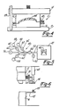
- FIGs 2 through 4 depict the major steps in the sequence of molding operations employed while carrying out the process of the present invention.
- a compression die set 10 has an upper moveable die 12 mounted on a moveable upper platen 14 and a lower fixed die 16 mounted on a fixed bed 18.
- the upper and lower dies 12, 16 are complementary and form a mold in the closed position.
- the upper and lower dies 12, 16 slideably mate along complementary vertical surfaces 20, 22 when the dies nest in a telescoping manner into the semi-closed and closed positions as shown in Figs. 3 and 4.
- the upper die 12 moves vertically relative to the fixed die 16 under the action of an actuator means 24 such as a hydraulic pneumatic actuator attached to a fixed upper platen 26 generally acting through a ram or rams attached to the moveable upper platen 14.
- the upper die 12 and associated moveable platen 14 move vertically along fixed vertical guide members 28 which maintain the dies in alignment.
- the lower end of guide 28 is rigidly mounted in the fixed lower bed 18.
- the dies 12, 16 have a vacuum seal 30 associated therewith.
- the seal portion attached to upper die 12 comprises an L-shaped bracket member 32 having a vertical leg 34 attached to the upper die and a horizontal leg 36 extending outward perpendicularly from the upper die.
- the L-shaped bracket has a tubular member 38 attached.
- a lower sealing means comprising a horizontally disposed shelf 40 extending perpendicularly away from lower die 16 and a raised pointed bead disposed on the shelf 40, the bead being adapted to engage the tube 38.
- the bead 42 will engage the tube 38 at an intermediate position, as shown in Fig. 3, before the dies are fully closed to form a sealed vacuum chamber 47 of which mold cavity 46 within the die set 10 is a part.
- the tubing diameter is large enough to form the seal before the molding compound 44 flows to fill the mold but there is sufficient travel allowed by the seal that the dies can be fully closed without seal damage.
- a piece of sheet molding compound 44 is placed on or in one of the dies when the dies are fully open. With the dies 12, 16 in the closed compression molding position shown in Fig. 4, the sheet molding compound 44 located within the cavity will slowly spread to fill the mold cavity 46 formed between the upper and lower dies.
- the dies are heated by steam, oil or other heating means in order to provide sufficient energy to cure the resin present in the sheet molding compound to a hard thermoset condition.
- the first step of any compression molding process is the provision of a die and cure base step 48 associated with a press suitable for applying the compressive force necessary to cause the sheet molding compound (SMC) to spread within the mold cavity as the mold is closed.
- the die is generally started in an open position step 50 with sufficient space between dies to allow the desired quantity of sheet molding compound, normally disposed as one or more sheets to be placed between the molds - step 52.
- the compound placed in the mold need not be formed in a rectangular shape and may have a configuration when viewed from the top like a dog bone or other configuration dictated by the flow of material within the die. Shaped charges are frequently used in order to equalize the time it takes for compound flowing from the charge to reach the outer portions of the mold.
- the die set 10 is closed to an evacuation position step 54 where the vacuum seal 30 is engaged and the interior cavity 46 of the die set is substantially sealed from the atmosphere as part of a vacuum chamber 47. This position will be reached before the upper die 12 contacts the SMC.
- the plastic flow is primarily in a substantially reduced pressure environment maintained within the vacuum chamber 47.
- the vacuum chamber 47 is evacuated in step 56 to the desired operating pressure.
- pressures will be reduced in the die cavity to approximately less than 7 inches of mercury absolute prior to final molding and curing of the sheet molding compound. Since many sheet molding compounds contain a quantity of low molecular weight monomeric or polymeric materials used as solvents, reactants, cross-linkers, or catalysts, it is desirable to minimize the SMC's exposure time to the reduced pressure prior to the molding and curing of the compound. Minimizing the exposure time will minimize the amount of low molecular weight constituents that are withdrawn from the body of the sheet molding compound by the reduced pressure. The vaporization of low molecular weight compounds in reduced pressure atmospheres is well known and further discussion is not necessary.
- polyester compounds having low shrink characteristics contain a certain amount of styrene monomer in addition to the primary polyester reactants and a thermoplastic material. Withdrawing excessive amounts of styrene from the surface of the part will result in macro porosity and possible discoloration of the parts. Therefore, where polyester resins are used, it is desired to limit the evacuation time of the vacuum chamber to no more than 20 seconds.
- the die is closed to its curing position in step 58 causing the sheet molding compound to spread and fill the mold cavity.
- the press is maintained in the closed curing position during step 60 with the pressure continuously being applied to insure that the presssure is uniformly distributed throughout the sheet molding compound. Simultaneously heat is applied to the dies in order to cause chemical reaction between the constituents of the thermosetting resin forming a hard thermoset material.
- the thermoset resin consolidates and holds the fibrous reinforcement in a rigid consolidated condition.
- the vacuum chamber 47 is returned to atmospheric pressure when the die has fully closed as shown in Fig. 4 since vacuum is not necessary and indeed may be harmful once the material has spread to completely fill the die cavity.
- Fig. 5 a schematic diagram of the die cavity 46, vacuum chamber 47 and associated vacuum apparatus 48.
- the vacuum apparatus has storage tanks, a vacuum pump and a plurality of valves.
- the die cavity 46 represents the schematic mold or die set, such as that shown in Figs. 3 and 4 located within vacuum chamber 47, which has a vacuum line 50 emanating from the interior of the chamber 47.
- the vacuum line 50 has an atmospheric exposure valve 52 attached to the vacuum line, the valve being operable between a first open position allowing atmospheric air to enter the valve in the vacuum line and a second closed position blocking the movement of air from the atmosphere into the vacuum line.
- a vacuum line control valve 54 is disposed in the vacuum line 50 between the atmospheric exposure valve 52 and a vacuum pump 56 and associated vacuum storage tanks 58. In the open position, vacuum valve 54 connects the vacuum pump 56 and associated vacuum storage tanks 58 to the vacuum line 50. In the closed position, vacuum line valve 54 isolates the pump and its associated storage tanks 58 from the remainder of the system.
- Three vacuum tanks 58 are shown separately connected to the terminus of the vacuum line by means of secondary vacuum lines 60 having secondary vacuum valve members disposed therein.
- the secondary vacuum valve 62 In the open position, the secondary vacuum valve 62 will expose the vacuum line to the vacuum present within an associated vacuum storage tank 58 and in the closed position will isolate the associated vacuum tank from the remainder of the system.
- the vacuum pump 56 is shown permanently connected to the terminus of the vacuum line 50.
- the vacuum pumps contemplated in the use of this invention can be positive displacement rotary vanes with an oil seal and water cooling. Such pumps are standard and well known in the art. Other forms of vacuum pumps can also be used.
- the vacuum tanks or vacuum surge tanks 58 used can be standard water or propane type tanks, said tanks having sufficient strength to withstand atmospheric pressure when the interior of the chamber has been evacuated to approximately 7 inches of mercury absolute.
- the atmospheric valve 52 will close and the vacuum line valve 54 will open exposing the interior of the mold cavity to the pumping action of the vacuum pump 56.
- a vacuum tank valve 62 will open for a short period of time, for example approximately 1 to 4 seconds and then close entrapping a substantial quantity of air contained in the vacuum chamber 47.
- a second vacuum tank valve will open for approximately 1 to 4 seconds withdrawing a substantial portion of the remaining atmosphere contained in the vacuum chamber 47 into the second associated vacuum tank at which time the second valve will close and a third valve will open exposing the vacuum chamber 47 to the rapid withdrawal action of the third associated vacuum tank.
- the vacuum pump will continue to pump the die cavity 46 until the desired reduced pressure is reached at which time the die will close to the pressing or part forming position shown in Fig. 4.
- the vacuum line valve 54 will close isolating the vacuum pump and associated tanks from the vacuum system and the atmospheric valve 52 will open allowing atmospheric pressure to flow back into the vacuum chamber 47.
- the vacuum tank valves 62 will open and the vacuum pump 56 will empty the vacuum tanks for the next molding cycle.
- the volume of the tanks to be used will depend on the volume of the die cavity when the mold is in the evacuating position.
- Using a vacuum tank having a volume approximately equal to the vacuum chamber to he evacuated will result in reducing the pressure in the vacuum chamber by a factor of approximately one-half each time an evacuated vacuum tank is exposed to the system.
- three tanks it is possible to reduce the pressure in the die cavity to about on-eighth of the beginning pressure in a matter of approximately 3 to 12 seconds. If greater reduction is necessary, use of larger chambers or more chambers is possible.
- a further way in which to reduce the amount of gas which must be removed from the vacuum chamber in order to achieve the desired pressure is to reduce its internal volume. Because the vacuum seal 30 is disposed about the periphery of the die, the vacuum chamber's volume which is contained within the vacuum seal can represent a considerable volume. This is especially true since the seal 30 must be shaped so as to allow it to function within the press necessitating certain compromises with respect to the shape of the seal and its location on the die set. Portions of the vacuum chamber which are not subjected to compression during the molding cycle, can be completely or partially filled with closed cell foam material which effectively reduces the volume to be evacuated during the evacuation cycle.
- the system has used three vacuum tanks. More vacuum tanks may be used if desired, however, vacuum tanks in excess of approximately four or five represent a substantial number of operations necessary to evacuate the vacuum chamber and the use of more than three tanks would generally not be desirable from a production standpoint.
- Use of only a single tank equal in volume to the space to be evacuated within the die cavity results in reducing the pressure by a factor of only one-half and has been found that the use of a plurality of tanks provides the desired rapid evacuation in the vacuum chamber without undue complexity of machinery and control mechanisms.
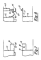
- Figs. 6, 7 and 8 show additional seal configurations useful in the practice of this invention.
- the exterior of upper die 12 has been finished to a smooth parallel condition.
- a moveable ring 64 is mounted on a horizontal arm 66 which extends radially inward from an air cylinder 68 mounted to the press frame (not shown).
- the moveable ring 64 has a wiper blade and seal 70 mounted in a position to contact the side wall of die 12.
- the lower die exterior has an L-shaped (in cross-section) collar 72 attached thereto with one flange extending perpendicularly outward from the die wall.
- a strip of tubing 73 such as silicone tubing is disposed on the upper surface of the collar where it is contacted by a horizontally extending flange 74 of moveable ring 64.
- the flange 74 will contact the tube 73 when the dies are closed to the evacuating position.
- Fig. 7 shows a sealing means formed of two complementary elastomeric members 76 and 78 disposed about the periphery of the upper die 12 and base 16.
- sealing member 76 has a lip 80 depending therefrom toward the second sealing member 78.
- the second sealing member has a complementary channel 82 adapted to receive the lip 80 to form a seal.
- Fig. 8 shows a seal means similar to Fig. 6 except moveable ring 64 has a flexible diaphragm 84 sealing the ring to the moveable upper die.
- the outer periphery of the diaphragm is attached to the moveable ring and the inner edge of the diaphragm is attached to the upper die.
Abstract
Description
- There has been an increased commercial use of parts which are molded from fiber reinforced resinous thermosetting materials. Such parts are generally made by compressing a mixture of resin and reinforcing fibers in a mold. The mold is generally formed of two or more pieces collectively called a mold set which is mounted within a press. When the separate dies of the die set are brought into proximity, these form a mold cavity which has the configuration of the finished part. The molds have associated heating means to heat and cure the resinous material to its thermoset condition. The materials most commonly used in molding techniques of this kind are resins which contain reinforcing fibers, such as glass, polyaramide or carbon fibers. The resin materials may also contain one or more solid particulate fillers. In general, such compounds are relatively viscous at room temperature and cure upon the application of heat via the heated mold set to a thermoset rigid condition.
- The resin materials are generally formed into a sheet molding compound for ease of handling, several sheets can be stacked forming a charge having a thickness greater than the finished part to be formed into a desired shape. Such a charge is placed on the lower mold half and upon the application of pressure and mild heat from the dies, the sheet molding compound flows to fill the mold cavity.
- Because the parts formed using these molding techniques are frequently complex in shape and include various ribs, bosses and other projections or complex dimensional configurations, not all portions of the mold are filled simultaneously. The uneven filling rate within the mold causes air to be entrapped within the molded part resulting in substantial porosity. The uneven filling can cause insufficient dispersion of the constituents within the mold. The porosity and non-uniform distribution, particularly of reinforcement fibers, cause surface problems. Air entrapment between layers will also create the aforementioned problems and lack of durability.
- Surface defects on the parts are undesirable for a number of different reasons. Many of the molded parts require that the part be capable of receiving a smooth glossy finish such as that commonly applied to painted metal surfaces in order to blend in properly with assemblies to which the part is attached. Secondly, a part with defects and excessive porosity requires additional labor and processing to repair the defects prior to finishing. Such extra steps result in substantial extra costs thereby lessening the ability of sheet molded compound parts to compete with ordinary metal stamping or castings.
- One method by which people have attempted to reduce surface porosity and increase the as molded smoothness of parts is reported in, The 33rd Annual Technical Conference, 1978, Reinforced Plastic Composite Institute, Section 9-F, pages 1-7. This article written by Gorsuch, et al, describes an attempt to make a low profile type sheet molding compound compression molding by drawing a vacuum on the mold cavity during molding. The authors of this article report that while there was an improvement in some areas of molding problems, there was "... however, simultaneously a generally acceptable increase in roughness and macro-porosity...". This article is indicative of the opinion held by those skilled in the sheet molding compound art that molding under vacuum was an unacceptable technique for achieving a smooth non-porous structure.
- An apparatus for compression molding according to the generic part of the main claim is described in US-A-3,840,239. This apparatus facilitates the evacuation of the cavity formed between two mold halves by the provision of an elastomeric vacuum seal fixedly and sealingly attached to the press portion of the compression molding press. The seal has a belt-like elastomeric wall member oriented generally vertically and a plurality of elongated reinforcing members fixedly mounted in contact with the wall member and oriented vertically. Also provided is a base portion for the molding press which has its outer surface slightly inclined inwardly toward the top. In operation, the base portion is raised relative to the press portion causing the vacuum seal to come into sealing and sliding engagement with the outer surface of the base portion, thereby sealing off the mold cavity from the surrounding atmosphere.
- It has been proven, however, that this molding press has a too complex design that is not justified by the degree of evacuation. This results mainly from the construction of the vacuum seal. Therefore, also the known molding press cannot enhance the quality of the molded parts.
- The problem to be solved by the invention is to allow sheet molding compounds to he molded under a vacuum without substantial increase in macro porosity or surface roughness resulting in an acceptable part which can be painted or otherwise finished and which is produced with no need for additional finishing steps or coating either within or without the mold.
- The invention solves this problem by the features of the main claim. Further developments of the invention are specified in the subclaims.
- This invention is useful in compression molding a sheet molding compound using heated dies which when closed form a mold. In general, molding comprises the steps of placing the compound to be molded within the mold cavity when the dies are open. The dies are closed to a partially closed position to engage a vacuum seal, thereby sealing the mold cavity and surrounding area to form a vacuum chamber, without the upper die contacting the sheet molding compound contained within the mold cavity. The vacuum chamber is then evacuated to a reduced pressure of less than 7 inches of mercury absolute followed by closing the dies to a fully closed condition. Upon closing the dies, the sheet molding compound will spread and fill the mold. Upon reaching the fully closed position wherein the sheet molding compound has completely filled the mold, the mold cavity is again returned to atmospheric pressure while the molding pressure is maintained on the part during the remainder of the curing cycle.
- After the part is thoroughly cured, the dies are opened allowing the removal of the finished part. In one embodiment of the apparatus of this invention a plurality of vacuum storage tanks are fluidly connected to the vacuum chamber. The vacuum tanks can be activated sequentially to withdraw a portion of the air within the mold cavity into the vacuum storage tank.
- In the accompanying drawing:
- Fig. 1 is a flow diagram illustrating the basic method of the present invention;
- Fig. 2 is a cross-sectional view of an open mold and sheet molding compound prior to compression molding;
- Fig. 3 is a sectioned side view of the mold Figure 3 in a partially closed, vacuum applying, position;
- Fig. 4 is a sectional side view of the mold of Fig. 3 in the fully closed compression molding position;
- Fig. 5 is a schematic diagram showing an arrangement for applying a vacuum to the mold cavity useful in the practice of this invention; and
- Fig. 6-8 show various means for sealing the mold cavity.
- Figures 2 through 4 depict the major steps in the sequence of molding operations employed while carrying out the process of the present invention. A
compression die set 10 has an uppermoveable die 12 mounted on a moveableupper platen 14 and a lower fixeddie 16 mounted on afixed bed 18. The upper andlower dies lower dies vertical surfaces - The upper die 12 moves vertically relative to the fixed
die 16 under the action of an actuator means 24 such as a hydraulic pneumatic actuator attached to a fixedupper platen 26 generally acting through a ram or rams attached to the moveableupper platen 14. The upper die 12 and associatedmoveable platen 14 move vertically along fixedvertical guide members 28 which maintain the dies in alignment. The lower end ofguide 28 is rigidly mounted in the fixedlower bed 18. - The
dies vacuum seal 30 associated therewith. As shown in Figs. 2-4, the seal portion attached toupper die 12 comprises an L-shaped bracket member 32 having avertical leg 34 attached to the upper die and ahorizontal leg 36 extending outward perpendicularly from the upper die. The L-shaped bracket has atubular member 38 attached. A lower sealing means comprising a horizontally disposedshelf 40 extending perpendicularly away fromlower die 16 and a raised pointed bead disposed on theshelf 40, the bead being adapted to engage thetube 38. Thebead 42 will engage thetube 38 at an intermediate position, as shown in Fig. 3, before the dies are fully closed to form a sealedvacuum chamber 47 of whichmold cavity 46 within thedie set 10 is a part. The tubing diameter is large enough to form the seal before themolding compound 44 flows to fill the mold but there is sufficient travel allowed by the seal that the dies can be fully closed without seal damage. - A piece of
sheet molding compound 44 is placed on or in one of the dies when the dies are fully open. With thedies sheet molding compound 44 located within the cavity will slowly spread to fill themold cavity 46 formed between the upper and lower dies. - As is common in compression molding techniques, the dies are heated by steam, oil or other heating means in order to provide sufficient energy to cure the resin present in the sheet molding compound to a hard thermoset condition.
- Referring to the flow diagram shown in Fig. 1, the first step of any compression molding process is the provision of a die and cure
base step 48 associated with a press suitable for applying the compressive force necessary to cause the sheet molding compound (SMC) to spread within the mold cavity as the mold is closed. The die is generally started in anopen position step 50 with sufficient space between dies to allow the desired quantity of sheet molding compound, normally disposed as one or more sheets to be placed between the molds -step 52. The compound placed in the mold need not be formed in a rectangular shape and may have a configuration when viewed from the top like a dog bone or other configuration dictated by the flow of material within the die. Shaped charges are frequently used in order to equalize the time it takes for compound flowing from the charge to reach the outer portions of the mold. - The die set 10 is closed to an
evacuation position step 54 where thevacuum seal 30 is engaged and theinterior cavity 46 of the die set is substantially sealed from the atmosphere as part of avacuum chamber 47. This position will be reached before the upper die 12 contacts the SMC. When practicing this invention, it is desired that the plastic flow is primarily in a substantially reduced pressure environment maintained within thevacuum chamber 47. - The
vacuum chamber 47 is evacuated instep 56 to the desired operating pressure. In general, pressures will be reduced in the die cavity to approximately less than 7 inches of mercury absolute prior to final molding and curing of the sheet molding compound. Since many sheet molding compounds contain a quantity of low molecular weight monomeric or polymeric materials used as solvents, reactants, cross-linkers, or catalysts, it is desirable to minimize the SMC's exposure time to the reduced pressure prior to the molding and curing of the compound. Minimizing the exposure time will minimize the amount of low molecular weight constituents that are withdrawn from the body of the sheet molding compound by the reduced pressure. The vaporization of low molecular weight compounds in reduced pressure atmospheres is well known and further discussion is not necessary. In particular, polyester compounds having low shrink characteristics contain a certain amount of styrene monomer in addition to the primary polyester reactants and a thermoplastic material. Withdrawing excessive amounts of styrene from the surface of the part will result in macro porosity and possible discoloration of the parts. Therefore, where polyester resins are used, it is desired to limit the evacuation time of the vacuum chamber to no more than 20 seconds. - After the mold is properly evacuated and the pressure therein has been reduced to approximately less than 7 inches of mercury absolute, the die is closed to its curing position in
step 58 causing the sheet molding compound to spread and fill the mold cavity. - The press is maintained in the closed curing position during
step 60 with the pressure continuously being applied to insure that the presssure is uniformly distributed throughout the sheet molding compound. Simultaneously heat is applied to the dies in order to cause chemical reaction between the constituents of the thermosetting resin forming a hard thermoset material. The thermoset resin consolidates and holds the fibrous reinforcement in a rigid consolidated condition. - The
vacuum chamber 47 is returned to atmospheric pressure when the die has fully closed as shown in Fig. 4 since vacuum is not necessary and indeed may be harmful once the material has spread to completely fill the die cavity. - Yet a further understanding can he had by referring to Fig. 5, a schematic diagram of the
die cavity 46,vacuum chamber 47 and associatedvacuum apparatus 48. The vacuum apparatus has storage tanks, a vacuum pump and a plurality of valves. As shown, thedie cavity 46 represents the schematic mold or die set, such as that shown in Figs. 3 and 4 located withinvacuum chamber 47, which has avacuum line 50 emanating from the interior of thechamber 47. Thevacuum line 50 has anatmospheric exposure valve 52 attached to the vacuum line, the valve being operable between a first open position allowing atmospheric air to enter the valve in the vacuum line and a second closed position blocking the movement of air from the atmosphere into the vacuum line. - A vacuum
line control valve 54 is disposed in thevacuum line 50 between theatmospheric exposure valve 52 and avacuum pump 56 and associatedvacuum storage tanks 58. In the open position,vacuum valve 54 connects thevacuum pump 56 and associatedvacuum storage tanks 58 to thevacuum line 50. In the closed position,vacuum line valve 54 isolates the pump and its associatedstorage tanks 58 from the remainder of the system. - Three
vacuum tanks 58 are shown separately connected to the terminus of the vacuum line by means ofsecondary vacuum lines 60 having secondary vacuum valve members disposed therein. In the open position, thesecondary vacuum valve 62 will expose the vacuum line to the vacuum present within an associatedvacuum storage tank 58 and in the closed position will isolate the associated vacuum tank from the remainder of the system. - The
vacuum pump 56 is shown permanently connected to the terminus of thevacuum line 50. The vacuum pumps contemplated in the use of this invention can be positive displacement rotary vanes with an oil seal and water cooling. Such pumps are standard and well known in the art. Other forms of vacuum pumps can also be used. - The vacuum tanks or
vacuum surge tanks 58 used can be standard water or propane type tanks, said tanks having sufficient strength to withstand atmospheric pressure when the interior of the chamber has been evacuated to approximately 7 inches of mercury absolute. - In operation, when the die set 10 has reached the evacuation position as shown in Fig. 3, and there is a vacuum seal, the
atmospheric valve 52 will close and thevacuum line valve 54 will open exposing the interior of the mold cavity to the pumping action of thevacuum pump 56. Avacuum tank valve 62 will open for a short period of time, for example approximately 1 to 4 seconds and then close entrapping a substantial quantity of air contained in thevacuum chamber 47. A second vacuum tank valve will open for approximately 1 to 4 seconds withdrawing a substantial portion of the remaining atmosphere contained in thevacuum chamber 47 into the second associated vacuum tank at which time the second valve will close and a third valve will open exposing thevacuum chamber 47 to the rapid withdrawal action of the third associated vacuum tank. After all three vacuum tanks have been opened in sequence, the vacuum pump will continue to pump thedie cavity 46 until the desired reduced pressure is reached at which time the die will close to the pressing or part forming position shown in Fig. 4. Once thedie 10 has reached its fully closed position, thevacuum line valve 54 will close isolating the vacuum pump and associated tanks from the vacuum system and theatmospheric valve 52 will open allowing atmospheric pressure to flow back into thevacuum chamber 47. After thevacuum line valve 54 has been closed, thevacuum tank valves 62 will open and thevacuum pump 56 will empty the vacuum tanks for the next molding cycle. - In general, the volume of the tanks to be used will depend on the volume of the die cavity when the mold is in the evacuating position. Using a vacuum tank having a volume approximately equal to the vacuum chamber to he evacuated will result in reducing the pressure in the vacuum chamber by a factor of approximately one-half each time an evacuated vacuum tank is exposed to the system. Thus, by using three tanks it is possible to reduce the pressure in the die cavity to about on-eighth of the beginning pressure in a matter of approximately 3 to 12 seconds. If greater reduction is necessary, use of larger chambers or more chambers is possible.
- A further way in which to reduce the amount of gas which must be removed from the vacuum chamber in order to achieve the desired pressure is to reduce its internal volume. Because the
vacuum seal 30 is disposed about the periphery of the die, the vacuum chamber's volume which is contained within the vacuum seal can represent a considerable volume. This is especially true since theseal 30 must be shaped so as to allow it to function within the press necessitating certain compromises with respect to the shape of the seal and its location on the die set. Portions of the vacuum chamber which are not subjected to compression during the molding cycle, can be completely or partially filled with closed cell foam material which effectively reduces the volume to be evacuated during the evacuation cycle. - As shown, the system has used three vacuum tanks. More vacuum tanks may be used if desired, however, vacuum tanks in excess of approximately four or five represent a substantial number of operations necessary to evacuate the vacuum chamber and the use of more than three tanks would generally not be desirable from a production standpoint. Use of only a single tank equal in volume to the space to be evacuated within the die cavity results in reducing the pressure by a factor of only one-half and has been found that the use of a plurality of tanks provides the desired rapid evacuation in the vacuum chamber without undue complexity of machinery and control mechanisms.
- Figs. 6, 7 and 8 show additional seal configurations useful in the practice of this invention. With reference initially to Fig. 6, the exterior of
upper die 12 has been finished to a smooth parallel condition. Amoveable ring 64 is mounted on ahorizontal arm 66 which extends radially inward from anair cylinder 68 mounted to the press frame (not shown). Themoveable ring 64 has a wiper blade and seal 70 mounted in a position to contact the side wall ofdie 12. The lower die exterior has an L-shaped (in cross-section)collar 72 attached thereto with one flange extending perpendicularly outward from the die wall. A strip of tubing 73 such as silicone tubing is disposed on the upper surface of the collar where it is contacted by a horizontally extendingflange 74 ofmoveable ring 64. Theflange 74 will contact the tube 73 when the dies are closed to the evacuating position. - Fig. 7 shows a sealing means formed of two complementary
elastomeric members upper die 12 andbase 16. As shown, sealingmember 76 has alip 80 depending therefrom toward the second sealingmember 78. The second sealing member has acomplementary channel 82 adapted to receive thelip 80 to form a seal. - Fig. 8 shows a seal means similar to Fig. 6 except
moveable ring 64 has aflexible diaphragm 84 sealing the ring to the moveable upper die. The outer periphery of the diaphragm is attached to the moveable ring and the inner edge of the diaphragm is attached to the upper die. - Various alternations and modifications of this invention will become apparent to those skilled in the art without departing from the scope of the invention as set out in the claims. It is to be understood that this invention is not limited to the illustrative embodiments set forth hereinabove.
Claims (7)
- Apparatus (10) for compression molding a part from a charge (44) of fibre reinforced resin compounds, said apparatus comprising:
upper (16) and lower (12) die members defining a mold cavity therebetween generally corresponding to the shape of the desired part when the dies are closed;
means (24) for moving the die members relative to each other, said means being operative to move the die members to an open position where the die members are spaced apart of sufficient distance to permit the charge to be placed on the lower mold; and said means being operative to move the die members to a fully closed position where the upper die member contacts the charge; and vacuum means (48) for evacuating said mold cavity, characterised by said means (24) for moving the die members being further operative to move the die members from said open position to a partially closed position where the mold cavity is essentially defined but the upper die remains spaced from the charge;
a fixed member providing a first horizontally extending surface (72) surrounding the lower die and connected thereto in a fluid-tight manner;
a vertically movable ring member (64) surrounding, yet spaced from, the upper die (12), which provides a second horizontal surface (74) substantially aligned with the first horizontal surface;
means independent from said means (24) for moving the die members for permitting said ring to move relative to said die members;
sealing means (70) extending between the ring (64) and upper die (12) providing a seal therebetween while permitting relative movement therebetween;
said first (72) and second surfaces (74) being arranged so as to cooperate to provide an air seal (73) therebetween when the die members are moved to the partially closed position thereby defining a sealed vacuum chamber surrounding the mold cavity;
and said means (24) for moving the die members being operable to move the upper die to the fully closed position after the vacuum chamber has been evacuated whereby the charge can flow to fill the mold cavity to form the finished part. - The apparatus of claim 1 wherein said sealing means (70) includes a wiper seal adapted to provide a wiping sealing engagement with exterior portions of the upper die (12).
- The apparatus of claim 2 wherein said ring member (64) is substantially L-shaped in cross-section including a vertically extending member, and wherein said wiper seal (70) is affixed to the vertically extending member of the ring.
- The apparatus of claim 1, 2 or 3 wherein the independent means for moving comprises cylinder means (68) connected to the ring operative to move the ring relative to the upper die.
- The apparatus of one of claims 1 to 4, wherein said vacuum means (48) is adapted to evacuate the sealed vacuum chamber to a reduced pressure of less than 18 cm of mercury absolute within less than 20 seconds.
- The apparatus of claim 5 wherein the vacuum means includes:
a plurality of tanks (58) each having a volume at least as great as the volume of the mold cavity (46);
a first set of valves (62), each valve being associated with one of the tanks;
a vacuum pump (56);
means for connecting the vacuum pump to each of the tanks through the first set of valves, operative to evacuate the tanks when the valves are open, with the valves being subsequently closed after evacuation of the tanks;
a passageway (50) connecting the tanks and the vacuum pump to the vacuum chamber (47); and
a second valve (54) in said passageway adapted to control fluid communication between the vacuum chamber and the pump and tanks. - The apparatus of claim 6 wherein said vacuum means further includes:
an atmospheric valve (52) adapted to expose the vacuum chamber (47) to atmospheric pressure whereby said atmospheric valve is closed and the second valve (54) opened when the die members are moved to the partially closed position, with the first set of valves (62) being adapted to sequentially open and close to thereby evacuate air in the mold cavity into the individual tanks, and wherein the second valve (54) is closed and the atmospheric valve (52) opened to reexpose the mold cavity to atmospheric pressure after the die members have been moved to the fully closed position.
Priority Applications (1)
| Application Number | Priority Date | Filing Date | Title |
|---|---|---|---|
| AT84901906T ATE66404T1 (en) | 1983-04-25 | 1984-04-25 | DEVICE FOR PRESS FORMING. |
Applications Claiming Priority (2)
| Application Number | Priority Date | Filing Date | Title |
|---|---|---|---|
| US488494 | 1983-04-25 | ||
| US06/488,494 US4488862A (en) | 1983-04-25 | 1983-04-25 | Compression molding apparatus having vacuum chamber |
Publications (3)
| Publication Number | Publication Date |
|---|---|
| EP0142530A1 EP0142530A1 (en) | 1985-05-29 |
| EP0142530A4 EP0142530A4 (en) | 1987-10-27 |
| EP0142530B1 true EP0142530B1 (en) | 1991-08-21 |
Family
ID=23939889
Family Applications (1)
| Application Number | Title | Priority Date | Filing Date |
|---|---|---|---|
| EP84901906A Expired - Lifetime EP0142530B1 (en) | 1983-04-25 | 1984-04-25 | Apparatus for compression molding |
Country Status (8)
| Country | Link |
|---|---|
| US (1) | US4488862A (en) |
| EP (1) | EP0142530B1 (en) |
| JP (2) | JPS60501153A (en) |
| AU (1) | AU568853B2 (en) |
| BR (1) | BR8406601A (en) |
| CA (1) | CA1217017A (en) |
| DE (1) | DE3484954D1 (en) |
| WO (1) | WO1984004273A1 (en) |
Families Citing this family (40)
| Publication number | Priority date | Publication date | Assignee | Title |
|---|---|---|---|---|
| US4855097A (en) * | 1983-04-25 | 1989-08-08 | The Budd Company | Compression molding a charge using vacuum |
| US4612149A (en) * | 1983-04-25 | 1986-09-16 | The Budd Company | Compression molding a charge using vacuum |
| EP0189400A1 (en) * | 1984-08-07 | 1986-08-06 | SILVESTER, Richard | Thrust augmenter |
| CA1267763A (en) * | 1986-03-19 | 1990-04-17 | Kenneth A. Iseler | Vacuum compression molding method using preheated charge |
| EP0299611A1 (en) * | 1987-06-05 | 1989-01-18 | Takeda Chemical Industries, Ltd. | Compression molding apparatus and method |
| US4867924A (en) * | 1988-04-22 | 1989-09-19 | The Budd Company | Method and apparatus for compression molding under vacuum |
| US4959189A (en) * | 1988-09-26 | 1990-09-25 | E. I. Du Pont De Nemours And Company | Process for forming a composite structure of thermoplastic polymer and sheet molding compound |
| US5001000A (en) * | 1988-09-26 | 1991-03-19 | E. I. Du Pont De Nemours And Company | Process for forming a composite structure of thermoplastic polymer and sheet molding compound |
| US5000997A (en) * | 1989-02-06 | 1991-03-19 | The Budd Company | Method for making a painted part and part made thereby |
| US5100935A (en) * | 1990-07-19 | 1992-03-31 | The Budd Company | Flexible sheet molding compound and method of making the same |
| US5268400A (en) * | 1990-07-19 | 1993-12-07 | The Budd Company | Flexible sheet molding compound and method of making the same |
| US5298212A (en) * | 1991-01-16 | 1994-03-29 | Surface Technologies, Inc. | Method for forming a laminated substrate |
| GB2272397A (en) * | 1992-10-14 | 1994-05-18 | Lotus Car | Moulding method and apparatus |
| ES2108602B1 (en) * | 1994-01-19 | 1998-07-16 | Hispano Mecano Electrica Sa | IMPROVEMENTS IN THE PROCEDURES FOR MOLDING POLYESTER AND SIMILAR. |
| US6106274A (en) * | 1995-08-30 | 2000-08-22 | The Budd Company | Molding apparatus with charge overflow |
| US5753164A (en) * | 1995-08-30 | 1998-05-19 | The Budd Company | Automated thermoset molding method |
| DE19648844C1 (en) * | 1996-11-26 | 1997-09-18 | Jenoptik Jena Gmbh | Forming microstructured components for embossing tool and formable material between chamber walls |
| US6146578A (en) * | 1997-10-09 | 2000-11-14 | Lear Corporation | Method for molding headliners |
| US6416841B1 (en) | 1997-12-10 | 2002-07-09 | Pechiney Emballage Flexible Europe | Tear tape for plastic packaging |
| US6264454B1 (en) | 1998-03-11 | 2001-07-24 | The Budd Company | Wrapped SMC charge method and apparatus |
| US6103150A (en) * | 1998-03-11 | 2000-08-15 | The Budd Company | Molding overflow feedback method |
| US6103032A (en) * | 1998-04-24 | 2000-08-15 | The Budd Company | Sheet molding compound manufacturing improvements |
| US6119750A (en) | 1998-04-24 | 2000-09-19 | The Budd Company | Sheet molding compound manufacturing improvements |
| US6533976B1 (en) * | 2000-03-07 | 2003-03-18 | Northrop Grumman Corporation | Method of fabricating ceramic matrix composites employing a vacuum mold procedure |
| US6805546B2 (en) * | 2001-10-24 | 2004-10-19 | Thyssenkrupp Budd Company | Vacuum assisted molding apparatus |
| US20070052123A1 (en) * | 2003-10-07 | 2007-03-08 | Vertech Hume Pty. Ltd. | Vertical moulding of long concrete articles |
| US8127691B2 (en) * | 2004-03-03 | 2012-03-06 | Fitzpatrick Technologies, Llc | SMC pallet |
| US20060081158A1 (en) * | 2004-10-19 | 2006-04-20 | Fitzpatrick Technologies, L.L.C. | Pultrusion pallet |
| US20060220273A1 (en) * | 2005-03-29 | 2006-10-05 | Armstrong Bradford D | Process for compression moulding liquid resins with structural reinforcements |
| US20070017422A1 (en) * | 2005-07-19 | 2007-01-25 | Fitzpatrick Technologies, Llc | Pallet with composite components |
| US20070017423A1 (en) * | 2005-07-19 | 2007-01-25 | Ingham Terry L | Pallet With Recycled Components |
| US7915089B2 (en) * | 2007-04-10 | 2011-03-29 | Infineon Technologies Ag | Encapsulation method |
| US8261673B2 (en) * | 2007-09-26 | 2012-09-11 | Fitzpatrick Technologies | Pallet with lead board |
| JP4578517B2 (en) * | 2007-12-26 | 2010-11-10 | Scivax株式会社 | Imprint apparatus and imprint method |
| US7968042B2 (en) * | 2008-04-16 | 2011-06-28 | Aptina Imaging Corporation | Method and apparatus for step-and-repeat molding |
| DE102012110307B4 (en) * | 2012-10-29 | 2020-01-23 | Kraussmaffei Technologies Gmbh | Process for the production of composite material components made of plastic by high-pressure resin transfer presses and associated high-pressure resin transfer press tool |
| CN103963318B (en) | 2013-01-29 | 2019-08-09 | 康廷南拓结构塑料有限公司 | The vacuum forming method of thermosetting property sheet-like article |
| EP2960036A1 (en) * | 2014-06-26 | 2015-12-30 | TCTech Sweden AB | Method and device for embossing/pressing |
| GB201610865D0 (en) * | 2016-06-22 | 2016-08-03 | Composite Tech And Applications Ltd | An apparatus for manufacturing a composite component |
| CN107243553A (en) * | 2017-06-29 | 2017-10-13 | 奇瑞汽车股份有限公司 | A kind of mould structure for being used to solve stamping parts deformation and stomata hole |
Family Cites Families (17)
| Publication number | Priority date | Publication date | Assignee | Title |
|---|---|---|---|---|
| US2452382A (en) * | 1945-04-30 | 1948-10-26 | Emmet S Long | Apparatus for molding rubber and plastic materials |
| FR1241907A (en) * | 1958-11-19 | 1960-09-23 | Straumann Inst Ag | Equipment for heat treatment under high vacuum |
| US3504070A (en) * | 1968-02-19 | 1970-03-31 | Comet Ind | Vacuum forming method and apparatus |
| US3871060A (en) * | 1971-12-29 | 1975-03-18 | Ladney M Jr | Method of constructing mold for forming plastic foam parts |
| US3959434A (en) * | 1972-07-17 | 1976-05-25 | M. Lowenstein & Sons, Inc. | Three dimensional decorative material and process for producing same |
| FR2197644A1 (en) * | 1972-08-31 | 1974-03-29 | Ferte Albert | Sterilising autoclave vacuum system - reduces sterilising cycle time and speeds evacuation of air from vessel |
| US3840239A (en) * | 1972-10-26 | 1974-10-08 | Gen Tire & Rubber Co | Compression molding in a vacuum and seal for use therein |
| IT1030195B (en) * | 1975-02-20 | 1979-03-30 | Marocco G | PROCEDURE AND EQUIPMENT FOR THE PRODUCTION OF BLOCKS OF MARBLE AND SIMILAR NATURAL STONES |
| US4076788A (en) * | 1976-12-02 | 1978-02-28 | General Motors Corporation | Mold coating of freshly molded articles |
| JPS5597929A (en) * | 1979-01-19 | 1980-07-25 | Matsushita Electric Ind Co Ltd | Production of flat plate-shaped body |
| JPS55158952A (en) * | 1979-05-30 | 1980-12-10 | Ootake Kikai Kogyo Kk | Moldng and vulcanizing of rubber |
| US4267142A (en) * | 1979-10-22 | 1981-05-12 | Lankheet Jay A | Reinforced resin molding method and apparatus |
| US4374080A (en) * | 1981-01-13 | 1983-02-15 | Indy Electronics, Inc. | Method and apparatus for encapsulation casting |
| US4416841A (en) * | 1981-03-11 | 1983-11-22 | Corea John E | Method for centrifugal casting of thermosetting plastics |
| JPS57187212A (en) * | 1981-05-12 | 1982-11-17 | Akira Washida | Vacuum molding apparatus |
| JPS581522A (en) * | 1981-06-25 | 1983-01-06 | Sekisui Chem Co Ltd | Preparation of frp |
| JPS6036417Y2 (en) * | 1982-11-22 | 1985-10-29 | 株式会社内藤製作所 | Vulcanization molding equipment |
-
1983
- 1983-04-25 US US06/488,494 patent/US4488862A/en not_active Expired - Lifetime
-
1984
- 1984-04-25 DE DE8484901906T patent/DE3484954D1/en not_active Expired - Fee Related
- 1984-04-25 EP EP84901906A patent/EP0142530B1/en not_active Expired - Lifetime
- 1984-04-25 BR BR8406601A patent/BR8406601A/en not_active IP Right Cessation
- 1984-04-25 JP JP59501845A patent/JPS60501153A/en active Granted
- 1984-04-25 WO PCT/US1984/000627 patent/WO1984004273A1/en active IP Right Grant
- 1984-04-25 AU AU28630/84A patent/AU568853B2/en not_active Ceased
- 1984-04-25 CA CA000452779A patent/CA1217017A/en not_active Expired
-
1991
- 1991-04-02 JP JP3069705A patent/JPH0651310B2/en not_active Expired - Lifetime
Also Published As
| Publication number | Publication date |
|---|---|
| AU568853B2 (en) | 1988-01-14 |
| JPH04219218A (en) | 1992-08-10 |
| EP0142530A4 (en) | 1987-10-27 |
| DE3484954D1 (en) | 1991-09-26 |
| BR8406601A (en) | 1985-03-12 |
| JPH04448B2 (en) | 1992-01-07 |
| CA1217017A (en) | 1987-01-27 |
| WO1984004273A1 (en) | 1984-11-08 |
| JPH0651310B2 (en) | 1994-07-06 |
| US4488862A (en) | 1984-12-18 |
| EP0142530A1 (en) | 1985-05-29 |
| AU2863084A (en) | 1984-11-19 |
| JPS60501153A (en) | 1985-07-25 |
Similar Documents
| Publication | Publication Date | Title |
|---|---|---|
| EP0142530B1 (en) | Apparatus for compression molding | |
| US4551085A (en) | Compression molding apparatus having vacuum chamber | |
| EP0189471B1 (en) | Compression molding a charge using vacuum | |
| US5130071A (en) | Vacuum compression molding method using preheated charge | |
| US3135640A (en) | Process of and an apparatus for manufacturing hollow articles from reinforced synthetic resins | |
| US2441097A (en) | Plastics molding apparatus | |
| US3267517A (en) | Apparatus for molding hardenable plastics in a vacuum | |
| US4855097A (en) | Compression molding a charge using vacuum | |
| AU636418B2 (en) | Reaction injection molding apparatus for forming fiber-resin forced molded article | |
| CA2170106C (en) | Resin transfer molding process | |
| US10471668B2 (en) | Vacuum molding of thermoset sheet articles | |
| WO1991017035A1 (en) | Method and apparatus for producing structural injection moldings | |
| JP3027607B2 (en) | Vacuum forming method for large objects made of synthetic resin | |
| CA1217018A (en) | Compression molding apparatus having vacuum chamber | |
| US3368239A (en) | Apparatus for molding impregnated glass fiber articles | |
| CN1009181B (en) | A kind of manufacture method of hollow body | |
| US3442998A (en) | Method for making impregnated fiber articles | |
| EP0553486A1 (en) | Tooling and process for moulding polymeric materials in the liquid state | |
| CN212241915U (en) | Convenient automobile upper decorative plate mold for injection molding | |
| KR820000557B1 (en) | Molding apparatus | |
| CN117445285A (en) | Composite helmet hot-press forming die, forming equipment and using method thereof | |
| EP1645387A1 (en) | System and method for gas suction in a mould for foaming | |
| JPH02204013A (en) | Mold and method for forming | |
| JPS63168320A (en) | Compression molding tool for thermosetting resin | |
| ES2070074A1 (en) | Improvements to the manufacture of container elements for pressurized fluids |
Legal Events
| Date | Code | Title | Description |
|---|---|---|---|
| PUAI | Public reference made under article 153(3) epc to a published international application that has entered the european phase |
Free format text: ORIGINAL CODE: 0009012 |
|
| 17P | Request for examination filed |
Effective date: 19850125 |
|
| AK | Designated contracting states |
Designated state(s): AT BE CH DE FR GB LI LU NL SE |
|
| A4 | Supplementary search report drawn up and despatched |
Effective date: 19871027 |
|
| 17Q | First examination report despatched |
Effective date: 19890309 |
|
| GRAA | (expected) grant |
Free format text: ORIGINAL CODE: 0009210 |
|
| AK | Designated contracting states |
Kind code of ref document: B1 Designated state(s): AT BE CH DE FR GB LI LU NL SE |
|
| PG25 | Lapsed in a contracting state [announced via postgrant information from national office to epo] |
Ref country code: LI Effective date: 19910821 Ref country code: CH Effective date: 19910821 Ref country code: BE Effective date: 19910821 Ref country code: AT Effective date: 19910821 |
|
| REF | Corresponds to: |
Ref document number: 66404 Country of ref document: AT Date of ref document: 19910915 Kind code of ref document: T |
|
| REF | Corresponds to: |
Ref document number: 3484954 Country of ref document: DE Date of ref document: 19910926 |
|
| REG | Reference to a national code |
Ref country code: CH Ref legal event code: PL |
|
| ET | Fr: translation filed | ||
| PG25 | Lapsed in a contracting state [announced via postgrant information from national office to epo] |
Ref country code: LU Free format text: LAPSE BECAUSE OF NON-PAYMENT OF DUE FEES Effective date: 19920430 |
|
| PLBE | No opposition filed within time limit |
Free format text: ORIGINAL CODE: 0009261 |
|
| STAA | Information on the status of an ep patent application or granted ep patent |
Free format text: STATUS: NO OPPOSITION FILED WITHIN TIME LIMIT |
|
| 26N | No opposition filed | ||
| EAL | Se: european patent in force in sweden |
Ref document number: 84901906.2 |
|
| PGFP | Annual fee paid to national office [announced via postgrant information from national office to epo] |
Ref country code: FR Payment date: 20010330 Year of fee payment: 18 |
|
| PGFP | Annual fee paid to national office [announced via postgrant information from national office to epo] |
Ref country code: SE Payment date: 20010402 Year of fee payment: 18 Ref country code: DE Payment date: 20010402 Year of fee payment: 18 |
|
| PGFP | Annual fee paid to national office [announced via postgrant information from national office to epo] |
Ref country code: GB Payment date: 20010403 Year of fee payment: 18 |
|
| PGFP | Annual fee paid to national office [announced via postgrant information from national office to epo] |
Ref country code: NL Payment date: 20010412 Year of fee payment: 18 |
|
| REG | Reference to a national code |
Ref country code: GB Ref legal event code: IF02 |
|
| PG25 | Lapsed in a contracting state [announced via postgrant information from national office to epo] |
Ref country code: GB Free format text: LAPSE BECAUSE OF NON-PAYMENT OF DUE FEES Effective date: 20020425 |
|
| PG25 | Lapsed in a contracting state [announced via postgrant information from national office to epo] |
Ref country code: SE Free format text: LAPSE BECAUSE OF NON-PAYMENT OF DUE FEES Effective date: 20020426 |
|
| PG25 | Lapsed in a contracting state [announced via postgrant information from national office to epo] |
Ref country code: NL Free format text: LAPSE BECAUSE OF NON-PAYMENT OF DUE FEES Effective date: 20021101 Ref country code: DE Free format text: LAPSE BECAUSE OF NON-PAYMENT OF DUE FEES Effective date: 20021101 |
|
| EUG | Se: european patent has lapsed |
Ref document number: 84901906.2 |
|
| GBPC | Gb: european patent ceased through non-payment of renewal fee |
Effective date: 20020425 |
|
| PG25 | Lapsed in a contracting state [announced via postgrant information from national office to epo] |
Ref country code: FR Free format text: LAPSE BECAUSE OF NON-PAYMENT OF DUE FEES Effective date: 20021231 |
|
| NLV4 | Nl: lapsed or anulled due to non-payment of the annual fee |
Effective date: 20021101 |
|
| REG | Reference to a national code |
Ref country code: FR Ref legal event code: ST |