EP0143638A2 - Method for making tubular structures for biomedical applications - Google Patents
Method for making tubular structures for biomedical applications Download PDFInfo
- Publication number
- EP0143638A2 EP0143638A2 EP84308196A EP84308196A EP0143638A2 EP 0143638 A2 EP0143638 A2 EP 0143638A2 EP 84308196 A EP84308196 A EP 84308196A EP 84308196 A EP84308196 A EP 84308196A EP 0143638 A2 EP0143638 A2 EP 0143638A2
- Authority
- EP
- European Patent Office
- Prior art keywords
- solid phase
- water
- desired shape
- plastic
- solvent
- Prior art date
- Legal status (The legal status is an assumption and is not a legal conclusion. Google has not performed a legal analysis and makes no representation as to the accuracy of the status listed.)
- Withdrawn
Links
Images

Classifications
-
- C—CHEMISTRY; METALLURGY
- C08—ORGANIC MACROMOLECULAR COMPOUNDS; THEIR PREPARATION OR CHEMICAL WORKING-UP; COMPOSITIONS BASED THEREON
- C08J—WORKING-UP; GENERAL PROCESSES OF COMPOUNDING; AFTER-TREATMENT NOT COVERED BY SUBCLASSES C08B, C08C, C08F, C08G or C08H
- C08J9/00—Working-up of macromolecular substances to porous or cellular articles or materials; After-treatment thereof
- C08J9/26—Working-up of macromolecular substances to porous or cellular articles or materials; After-treatment thereof by elimination of a solid phase from a macromolecular composition or article, e.g. leaching out
-
- A—HUMAN NECESSITIES
- A61—MEDICAL OR VETERINARY SCIENCE; HYGIENE
- A61F—FILTERS IMPLANTABLE INTO BLOOD VESSELS; PROSTHESES; DEVICES PROVIDING PATENCY TO, OR PREVENTING COLLAPSING OF, TUBULAR STRUCTURES OF THE BODY, e.g. STENTS; ORTHOPAEDIC, NURSING OR CONTRACEPTIVE DEVICES; FOMENTATION; TREATMENT OR PROTECTION OF EYES OR EARS; BANDAGES, DRESSINGS OR ABSORBENT PADS; FIRST-AID KITS
- A61F2/00—Filters implantable into blood vessels; Prostheses, i.e. artificial substitutes or replacements for parts of the body; Appliances for connecting them with the body; Devices providing patency to, or preventing collapsing of, tubular structures of the body, e.g. stents
- A61F2/02—Prostheses implantable into the body
- A61F2/04—Hollow or tubular parts of organs, e.g. bladders, tracheae, bronchi or bile ducts
- A61F2/06—Blood vessels
-
- A—HUMAN NECESSITIES
- A61—MEDICAL OR VETERINARY SCIENCE; HYGIENE
- A61L—METHODS OR APPARATUS FOR STERILISING MATERIALS OR OBJECTS IN GENERAL; DISINFECTION, STERILISATION OR DEODORISATION OF AIR; CHEMICAL ASPECTS OF BANDAGES, DRESSINGS, ABSORBENT PADS OR SURGICAL ARTICLES; MATERIALS FOR BANDAGES, DRESSINGS, ABSORBENT PADS OR SURGICAL ARTICLES
- A61L27/00—Materials for grafts or prostheses or for coating grafts or prostheses
- A61L27/50—Materials characterised by their function or physical properties, e.g. injectable or lubricating compositions, shape-memory materials, surface modified materials
- A61L27/56—Porous materials, e.g. foams or sponges
-
- B—PERFORMING OPERATIONS; TRANSPORTING
- B29—WORKING OF PLASTICS; WORKING OF SUBSTANCES IN A PLASTIC STATE IN GENERAL
- B29C—SHAPING OR JOINING OF PLASTICS; SHAPING OF MATERIAL IN A PLASTIC STATE, NOT OTHERWISE PROVIDED FOR; AFTER-TREATMENT OF THE SHAPED PRODUCTS, e.g. REPAIRING
- B29C48/00—Extrusion moulding, i.e. expressing the moulding material through a die or nozzle which imparts the desired form; Apparatus therefor
- B29C48/03—Extrusion moulding, i.e. expressing the moulding material through a die or nozzle which imparts the desired form; Apparatus therefor characterised by the shape of the extruded material at extrusion
- B29C48/09—Articles with cross-sections having partially or fully enclosed cavities, e.g. pipes or channels
-
- B—PERFORMING OPERATIONS; TRANSPORTING
- B29—WORKING OF PLASTICS; WORKING OF SUBSTANCES IN A PLASTIC STATE IN GENERAL
- B29C—SHAPING OR JOINING OF PLASTICS; SHAPING OF MATERIAL IN A PLASTIC STATE, NOT OTHERWISE PROVIDED FOR; AFTER-TREATMENT OF THE SHAPED PRODUCTS, e.g. REPAIRING
- B29C48/00—Extrusion moulding, i.e. expressing the moulding material through a die or nozzle which imparts the desired form; Apparatus therefor
- B29C48/16—Articles comprising two or more components, e.g. co-extruded layers
- B29C48/18—Articles comprising two or more components, e.g. co-extruded layers the components being layers
- B29C48/21—Articles comprising two or more components, e.g. co-extruded layers the components being layers the layers being joined at their surfaces
-
- B—PERFORMING OPERATIONS; TRANSPORTING
- B29—WORKING OF PLASTICS; WORKING OF SUBSTANCES IN A PLASTIC STATE IN GENERAL
- B29C—SHAPING OR JOINING OF PLASTICS; SHAPING OF MATERIAL IN A PLASTIC STATE, NOT OTHERWISE PROVIDED FOR; AFTER-TREATMENT OF THE SHAPED PRODUCTS, e.g. REPAIRING
- B29C48/00—Extrusion moulding, i.e. expressing the moulding material through a die or nozzle which imparts the desired form; Apparatus therefor
- B29C48/25—Component parts, details or accessories; Auxiliary operations
- B29C48/30—Extrusion nozzles or dies
- B29C48/32—Extrusion nozzles or dies with annular openings, e.g. for forming tubular articles
- B29C48/335—Multiple annular extrusion nozzles in coaxial arrangement, e.g. for making multi-layered tubular articles
-
- B—PERFORMING OPERATIONS; TRANSPORTING
- B29—WORKING OF PLASTICS; WORKING OF SUBSTANCES IN A PLASTIC STATE IN GENERAL
- B29C—SHAPING OR JOINING OF PLASTICS; SHAPING OF MATERIAL IN A PLASTIC STATE, NOT OTHERWISE PROVIDED FOR; AFTER-TREATMENT OF THE SHAPED PRODUCTS, e.g. REPAIRING
- B29C67/00—Shaping techniques not covered by groups B29C39/00 - B29C65/00, B29C70/00 or B29C73/00
- B29C67/20—Shaping techniques not covered by groups B29C39/00 - B29C65/00, B29C70/00 or B29C73/00 for porous or cellular articles, e.g. of foam plastics, coarse-pored
- B29C67/202—Shaping techniques not covered by groups B29C39/00 - B29C65/00, B29C70/00 or B29C73/00 for porous or cellular articles, e.g. of foam plastics, coarse-pored comprising elimination of a solid or a liquid ingredient
-
- B—PERFORMING OPERATIONS; TRANSPORTING
- B29—WORKING OF PLASTICS; WORKING OF SUBSTANCES IN A PLASTIC STATE IN GENERAL
- B29C—SHAPING OR JOINING OF PLASTICS; SHAPING OF MATERIAL IN A PLASTIC STATE, NOT OTHERWISE PROVIDED FOR; AFTER-TREATMENT OF THE SHAPED PRODUCTS, e.g. REPAIRING
- B29C48/00—Extrusion moulding, i.e. expressing the moulding material through a die or nozzle which imparts the desired form; Apparatus therefor
- B29C48/001—Combinations of extrusion moulding with other shaping operations
- B29C48/0012—Combinations of extrusion moulding with other shaping operations combined with shaping by internal pressure generated in the material, e.g. foaming
-
- B—PERFORMING OPERATIONS; TRANSPORTING
- B29—WORKING OF PLASTICS; WORKING OF SUBSTANCES IN A PLASTIC STATE IN GENERAL
- B29C—SHAPING OR JOINING OF PLASTICS; SHAPING OF MATERIAL IN A PLASTIC STATE, NOT OTHERWISE PROVIDED FOR; AFTER-TREATMENT OF THE SHAPED PRODUCTS, e.g. REPAIRING
- B29C48/00—Extrusion moulding, i.e. expressing the moulding material through a die or nozzle which imparts the desired form; Apparatus therefor
- B29C48/03—Extrusion moulding, i.e. expressing the moulding material through a die or nozzle which imparts the desired form; Apparatus therefor characterised by the shape of the extruded material at extrusion
- B29C48/09—Articles with cross-sections having partially or fully enclosed cavities, e.g. pipes or channels
- B29C48/10—Articles with cross-sections having partially or fully enclosed cavities, e.g. pipes or channels flexible, e.g. blown foils
-
- B—PERFORMING OPERATIONS; TRANSPORTING
- B29—WORKING OF PLASTICS; WORKING OF SUBSTANCES IN A PLASTIC STATE IN GENERAL
- B29K—INDEXING SCHEME ASSOCIATED WITH SUBCLASSES B29B, B29C OR B29D, RELATING TO MOULDING MATERIALS OR TO MATERIALS FOR MOULDS, REINFORCEMENTS, FILLERS OR PREFORMED PARTS, e.g. INSERTS
- B29K2105/00—Condition, form or state of moulded material or of the material to be shaped
- B29K2105/04—Condition, form or state of moulded material or of the material to be shaped cellular or porous
-
- B—PERFORMING OPERATIONS; TRANSPORTING
- B29—WORKING OF PLASTICS; WORKING OF SUBSTANCES IN A PLASTIC STATE IN GENERAL
- B29L—INDEXING SCHEME ASSOCIATED WITH SUBCLASS B29C, RELATING TO PARTICULAR ARTICLES
- B29L2023/00—Tubular articles
-
- B—PERFORMING OPERATIONS; TRANSPORTING
- B29—WORKING OF PLASTICS; WORKING OF SUBSTANCES IN A PLASTIC STATE IN GENERAL
- B29L—INDEXING SCHEME ASSOCIATED WITH SUBCLASS B29C, RELATING TO PARTICULAR ARTICLES
- B29L2031/00—Other particular articles
- B29L2031/753—Medical equipment; Accessories therefor
- B29L2031/7532—Artificial members, protheses
- B29L2031/7534—Cardiovascular protheses
Definitions
- This invention relates to porous polymer structures. More particularly, it relates to porous synthetic polymer tubular structures useful as vascular prostheses.
- the water soluble salt is then leached out to leave interconnected pores in a polymer matrix.
- Porosity can be varied throughout wall thickness by laminating layers of different pore size. In some cases, it may be desirable to have one layer of the composite non-porous. It is advantageous to be able to provide a controlled porosity gradient through the vascular prosthesis wall, because tissue ingrowth from the inner or blood side is of a different nature than that ingrowing from the outer or soft tissue side. In general, a smaller inside pore size is desired compared with that of the outside.
- the solvent used is chosen to be not only a good solvent for the polymer, but water miscible and not necessarily especially volatile.
- the viscous polymer dispersion with water soluble particles can be extruded through a tube dye into water where both the solvent and particulate matter are simultaneously dissolved away from the water insoluble polymer.
- the polymer is coagulated as a tube with open pores in the walls where particles had been.
- the chosen solvent and the pore forming particles must be relatively non-toxic so that small traces remaining in a prosthesis will not cause adverse reaction in the body.
- porosity can be made to vary through the tube wall by forming polymer dispersions of particles with different particle size distribution, and co-extruding them in a concentric tube dye as a multilayer tube. There is no need to form separate layers and then be required to laminate those separate parts together as required by the Canadian and British methods.
- Figure 1 is a schematic diagram of a preferred process according to this invention.
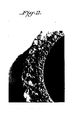
- Figure 2 is a cross section view magnified 30 times of a dual layer tube as produced by the process of Figure 1.
- a particularly useful product made by the process of this invention is a flexible porous tube in the form of a vascular prosthesis in which the average pore size on the inside tube surface is relatively small while the average pore on the outer surface is larger.
- the process of this invention is well suited to the production of such a variable porosity tube.
- FIG. 1 is a schematic flow sheet of a preferred process for making a two layer vascular prosthesis.
- each dispersion comprises a body-compatible, water insoluble, inherently flexible polymer dissolved in a water miscible solvent and contains a solid phase of a preselected particle size distribution dispersed in it. It has been found that pore size in the final product is approximately equal to particle size of the solid phase used. Therefore, the preselected particle size of solid phase will be approximately that of the desired product pore size. This solid phase must be substantially insoluble in the solvent-polymer solution, but soluble in water.
- Dispersion A which creates the outer tube layer, will contain larger insoluble particles than will Dispersion B. Consequently, the outer surface of tube wall will have larger pores than the inner surface.
- the two viscous dispersions are extruded through a concentric tube dye while water is introduced to the tube interior. The whole is extruded into a water bath. The two polymer dispersions leaving the concentric dye openings merge into a single tube. The high viscosity of these dispersions limits interdiffusion, so a tubular extrusion with concentric layers is formed. This extrusion being surrounded by water, there is a simultaneous extraction of the water soluble ingredients and coagulation of the polymer.
- the mechanism of pore formation is not known, but one possibility may be that the solvent is quickly leached into the surrounding water, causing the polymer to coagulate around the more slowly dissolving particles, initially forming a closed structure. Continued leaching by water dissolves away the particles leaving voids in the polymer tube, and producing an open porous sponge-like tube wall. A drying step to remove water completes the basic process. The process can be virtually continuous.
- Figure 2 shows in 30 power magnification the dual layer porous structure of a tube made by the process of Figure l.
- the operation of this new process to produce a vascular prosthesis requires that the starting ingredients have special properties. All ingredients must be relatively non-toxic to the human body.
- the polymer must be water insoluble and stable for long term exposure within the body. Further, the polymer must be substantially soluble in a solvent that is water miscible. The solvent, in addition to being relatively non-toxic and water miscible, must not have such an odor that residual traces in the product would be objectionable.
- the solid phase material must be substantially insoluble in the solvent used and in the polymer solvent solution. It must be readily soluble in water and easily produced in a range of desired particle size distributions. An inorganic salt is preferred.
- Useful concentrations of the polymer in solvent solution have ranged from about 1 to about 50 weight percent.
- the solid phase salt concentration is conveniently expressed as a weight percent of the polymer. Since each salt particle, or clump of particles, of significant size when dispersed in the polymer-solvent solution will result in an approximately equivalent sized pore, both the number concentration and average size of salt particles must be taken into account when planning a desired tube wall texture.
- Salt crystals with average particle sizes ranging from about 1 micron to about 250 microns in diameter are useful in concentrations of about 0.01 to about 100 weight percent of the polyurethane. These concentrations create pore volumes of about 1 to 90 percent in the product. Extruded wall thicknesses can be varied from about .010" to about 0.500". Tubes as small as lmm internal diameter and as large as 50mm internal diameter can be produced.
- a tube may be made from a single polymer dispersion and relatively uniform in properties throughout, or from several dispersions resulting in multiple layers, or even longitudinal stripes and other patterns, of different porosity. It is sometimes useful to have a tube containing a non-porous layer. In that case, one of the polymer feeds to the extruder would contain no insoluble salt particles, and thus coagulate into a layer containing no pores.
- tubes can be made by this process for many different uses. Also, this process is adaptable to form other shapes than tubes. If desired, the polymer can be formulated to result in a relatively rigid structure, rather than a flexible one. In multi-layer products, not only can the porosity be varied, but different polymers can be. used in the different layers. Among products contemplated other than vascular prostheses are drainage tubes, blood filters, cannulae, and trachea prostheses. The process can also make porous plastic forms reinforced with fibers and fillers.
- the polymer dispersion can be concentrated, having a highly viscous, putty-like consistancy. Such a dis- p ersion can be formed into a desired shape, and it will hold that shape through subsequent processing steps.
- the shaped dispersion is extracted with water to simultaneously leach out solvent and solid particles, and to coagulate the polymer into porous form.
- the inner layer and outer layer were formed from the viscous dispersions A and B, respectively.
- the extrusion was allowed to proceed in a 23°C coagulation bath followed by a 24 hour soak at 37°C. in the leach tank.
- the extrusion was allowed to dry at 13°C.
- the resultant tube exhibited an open porous structure with pore sizes roughly equivalent to the 250 micron crystal for the outer layer and 1 micron for the inner layer.
- Dispersions A and B were extruded in the same manner described with the following change in Dispersion B: 10% petroleum jelly was added to the formulation. The tube was treated as before except that a surfactant washing step was added after leaching. The resultant tube exhibited similar porosity to that of Example 1.
- Example 2 The same process was run on each dispersion separately and processed as described in Example 1, using a single tube dye in each case.
- the resultant single extrusions yielded tubes with pore sizes consistent with the sizes of crystal mixed into the polymer in each case.
Abstract
Description
- This invention relates to porous polymer structures. More particularly, it relates to porous synthetic polymer tubular structures useful as vascular prostheses.
- Experience has shown that for a synthetic vascular prosthesis to be successful it must possess a number of special chemical and physical properties. It must be non-toxic and chemically stable, and unaffected by prolonged contact with body fluids. It must be flexible, to conform to a desired shape and adjust to body movements; stiff enough to retain its passageway open even when bent; tough enough to hold suturing threads; and porous to permit tissue ingrowth. This combination of requirements has been sought with varying degrees of success in the past by a variety of structures. Widest use has been made of woven and knitted fabric tubes, typically made of polyester fibers. Also used have been porous expanded polytetrafluoroethylene plastic, non-woven felt and paper.
- Recently, different types of tubular structures were disclosed in Canadian Patent No. 1,092,303 and British Patent No. 1,552,388. The walls of these tubes are entirely, or in part, composed of inert sponge-like polymer. This spongy polymer has about 10 to about 70% pore volume. The pores are interconnected and about 1 micron to about 1,000 microns in size. This structure is created by dissolving a blood compatible polymer in a volatile solvent to create a viscous solution. A solvent insoluble, but water soluble, salt of a particle size approximately equal to the pore size desired is dispersed in the viscous solution. This viscous dispersion is formed into a desired shape, and dried of solvent. The water soluble salt is then leached out to leave interconnected pores in a polymer matrix. Porosity can be varied throughout wall thickness by laminating layers of different pore size. In some cases, it may be desirable to have one layer of the composite non-porous. It is advantageous to be able to provide a controlled porosity gradient through the vascular prosthesis wall, because tissue ingrowth from the inner or blood side is of a different nature than that ingrowing from the outer or soft tissue side. In general, a smaller inside pore size is desired compared with that of the outside.
- A superior way has now been discovered to produce a tubular vascular prosthesis of the type disclosed in the above Canadian and British patents. In this new process, the solvent used is chosen to be not only a good solvent for the polymer, but water miscible and not necessarily especially volatile. With that change, the viscous polymer dispersion with water soluble particles can be extruded through a tube dye into water where both the solvent and particulate matter are simultaneously dissolved away from the water insoluble polymer. Thus, the polymer is coagulated as a tube with open pores in the walls where particles had been. The chosen solvent and the pore forming particles must be relatively non-toxic so that small traces remaining in a prosthesis will not cause adverse reaction in the body.
- In this new process, porosity can be made to vary through the tube wall by forming polymer dispersions of particles with different particle size distribution, and co-extruding them in a concentric tube dye as a multilayer tube. There is no need to form separate layers and then be required to laminate those separate parts together as required by the Canadian and British methods.
- Therefore, it is an object of this invention to provide a process for making tubular structures of controlled porosity. It is another object to provide a process for forming in one step tubular structures in which porosity can be varied through the tube wall. It is still another object to provide an essentially continuous process for making porous polymer structures.
- Figure 1 is a schematic diagram of a preferred process according to this invention. Figure 2 is a cross section view magnified 30 times of a dual layer tube as produced by the process of Figure 1.
- A particularly useful product made by the process of this invention is a flexible porous tube in the form of a vascular prosthesis in which the average pore size on the inside tube surface is relatively small while the average pore on the outer surface is larger. The process of this invention is well suited to the production of such a variable porosity tube.
- Figure 1 is a schematic flow sheet of a preferred process for making a two layer vascular prosthesis. In this process, separate polymer dispersions are formed, one for each of the two different porosity layers. Each dispersion comprises a body-compatible, water insoluble, inherently flexible polymer dissolved in a water miscible solvent and contains a solid phase of a preselected particle size distribution dispersed in it. It has been found that pore size in the final product is approximately equal to particle size of the solid phase used. Therefore, the preselected particle size of solid phase will be approximately that of the desired product pore size. This solid phase must be substantially insoluble in the solvent-polymer solution, but soluble in water.
- In the Figure 1 process, Dispersion A, which creates the outer tube layer, will contain larger insoluble particles than will Dispersion B. Consequently, the outer surface of tube wall will have larger pores than the inner surface.
- The two viscous dispersions are extruded through a concentric tube dye while water is introduced to the tube interior. The whole is extruded into a water bath. The two polymer dispersions leaving the concentric dye openings merge into a single tube. The high viscosity of these dispersions limits interdiffusion, so a tubular extrusion with concentric layers is formed. This extrusion being surrounded by water, there is a simultaneous extraction of the water soluble ingredients and coagulation of the polymer.
- The mechanism of pore formation is not known, but one possibility may be that the solvent is quickly leached into the surrounding water, causing the polymer to coagulate around the more slowly dissolving particles, initially forming a closed structure. Continued leaching by water dissolves away the particles leaving voids in the polymer tube, and producing an open porous sponge-like tube wall. A drying step to remove water completes the basic process. The process can be virtually continuous.
- Figure 2 shows in 30 power magnification the dual layer porous structure of a tube made by the process of Figure l.
- The operation of this new process to produce a vascular prosthesis requires that the starting ingredients have special properties. All ingredients must be relatively non-toxic to the human body. The polymer must be water insoluble and stable for long term exposure within the body. Further, the polymer must be substantially soluble in a solvent that is water miscible. The solvent, in addition to being relatively non-toxic and water miscible, must not have such an odor that residual traces in the product would be objectionable.
- The solid phase material must be substantially insoluble in the solvent used and in the polymer solvent solution. It must be readily soluble in water and easily produced in a range of desired particle size distributions. An inorganic salt is preferred.
- While a number of ingredients may be suitable in this process, the preferred ones are: for polymer, a polyether-urethane, such as those supplied under the names "BIOMER" (Johnson & Johnson Inc.) and "PELLATHANE" (The Upjohn Company); for solvent, dimethylformamide; for solid phase, sodium chloride crystals. Useful concentrations of the polymer in solvent solution have ranged from about 1 to about 50 weight percent. The solid phase salt concentration is conveniently expressed as a weight percent of the polymer. Since each salt particle, or clump of particles, of significant size when dispersed in the polymer-solvent solution will result in an approximately equivalent sized pore, both the number concentration and average size of salt particles must be taken into account when planning a desired tube wall texture. Salt crystals with average particle sizes ranging from about 1 micron to about 250 microns in diameter are useful in concentrations of about 0.01 to about 100 weight percent of the polyurethane. These concentrations create pore volumes of about 1 to 90 percent in the product. Extruded wall thicknesses can be varied from about .010" to about 0.500". Tubes as small as lmm internal diameter and as large as 50mm internal diameter can be produced.
- This process is adaptable to make a wide range of product porosities. A tube may be made from a single polymer dispersion and relatively uniform in properties throughout, or from several dispersions resulting in multiple layers, or even longitudinal stripes and other patterns, of different porosity. It is sometimes useful to have a tube containing a non-porous layer. In that case, one of the polymer feeds to the extruder would contain no insoluble salt particles, and thus coagulate into a layer containing no pores.
- It will be appreciated that tubes can be made by this process for many different uses. Also, this process is adaptable to form other shapes than tubes. If desired, the polymer can be formulated to result in a relatively rigid structure, rather than a flexible one. In multi-layer products, not only can the porosity be varied, but different polymers can be. used in the different layers. Among products contemplated other than vascular prostheses are drainage tubes, blood filters, cannulae, and trachea prostheses. The process can also make porous plastic forms reinforced with fibers and fillers.
- In an alternate process according to this invention, the polymer dispersion can be concentrated, having a highly viscous, putty-like consistancy. Such a dis- persion can be formed into a desired shape, and it will hold that shape through subsequent processing steps. The shaped dispersion is extracted with water to simultaneously leach out solvent and solid particles, and to coagulate the polymer into porous form. An advantage of this alternate process is that it can be used to produce intricate shapes impossible to extrude and porous polymer coatings on otherwise solid protheses.
- The present invention is illustrated by the following examples. It will however, be understood that the invention is not limited to the specific details and conditions of these examples.
- A 30;% solution (Solution A) of the polyether- urethane "BIOMER" λ(solution Grade) in dimethylformamide (DMF) was mixed with sodium chloride (NaCl) crystals of average size 1 micron in a 1:1 weight ratio of NaCl to polymer to form a viscous dispersion A. Another 30% solution (Solution B) of the same polyether-urethane in DMF was mixed with NaCl crystals of average size 250 micron in a 1:2 weight ratio of NaCl to polymer to form a similar dispersion B. Dispersion A and Dispersion B were extruded through a co-extrusion process as depicted in the process diagram. The inner layer and outer layer were formed from the viscous dispersions A and B, respectively. The extrusion was allowed to proceed in a 23°C coagulation bath followed by a 24 hour soak at 37°C. in the leach tank. The extrusion was allowed to dry at 13°C. The resultant tube exhibited an open porous structure with pore sizes roughly equivalent to the 250 micron crystal for the outer layer and 1 micron for the inner layer.
- Dispersions A and B were extruded in the same manner described with the following change in Dispersion B: 10% petroleum jelly was added to the formulation. The tube was treated as before except that a surfactant washing step was added after leaching. The resultant tube exhibited similar porosity to that of Example 1.
- The same process was run on each dispersion separately and processed as described in Example 1, using a single tube dye in each case. The resultant single extrusions yielded tubes with pore sizes consistent with the sizes of crystal mixed into the polymer in each case.
Claims (8)
Applications Claiming Priority (2)
| Application Number | Priority Date | Filing Date | Title |
|---|---|---|---|
| US55574483A | 1983-11-28 | 1983-11-28 | |
| US555744 | 1983-11-28 |
Publications (2)
| Publication Number | Publication Date |
|---|---|
| EP0143638A2 true EP0143638A2 (en) | 1985-06-05 |
| EP0143638A3 EP0143638A3 (en) | 1987-09-30 |
Family
ID=24218442
Family Applications (1)
| Application Number | Title | Priority Date | Filing Date |
|---|---|---|---|
| EP84308196A Withdrawn EP0143638A3 (en) | 1983-11-28 | 1984-11-27 | Method for making tubular structures for biomedical applications |
Country Status (2)
| Country | Link |
|---|---|
| EP (1) | EP0143638A3 (en) |
| JP (1) | JPS60248750A (en) |
Cited By (12)
| Publication number | Priority date | Publication date | Assignee | Title |
|---|---|---|---|---|
| EP0286220A1 (en) * | 1987-04-09 | 1988-10-12 | Newtec Vascular Products Ltd. | Methods and apparatus for making polymer material |
| EP0308102A1 (en) * | 1987-09-04 | 1989-03-22 | Ube Industries, Ltd. | Process for preparing an artificial blood vessel |
| US4927410A (en) * | 1988-11-18 | 1990-05-22 | University Of South Florida | Method for fabricating prosthesis material |
| WO1990005628A1 (en) * | 1988-11-22 | 1990-05-31 | Newtec V.P. Limited | Composite structure |
| EP0430439A2 (en) * | 1989-11-21 | 1991-06-05 | Imperial Chemical Industries Plc | Extruded structure |
| US5081161A (en) * | 1990-06-15 | 1992-01-14 | E. I. Du Pont De Nemours And Company | Process for making shaped articles of a thermoplastic resin having a microcellular structure |
| WO1997042911A1 (en) * | 1996-05-15 | 1997-11-20 | Medtronic, Inc. | Intraluminal stent |
| EP0914918A2 (en) * | 1997-05-30 | 1999-05-12 | Schneider (Usa) Inc. | Porous tubular prostheses and method for making the same co-spraying water soluble and water insoluble fibrous components onto a rotating mandrel |
| WO2003064509A2 (en) * | 2002-02-01 | 2003-08-07 | Universiteit Twente | Method for preparing a porous polymer structure |
| DE102010020662A1 (en) * | 2010-05-05 | 2011-11-10 | Aesculap Ag | Medical implant |
| DE102010020663A1 (en) * | 2010-05-05 | 2011-11-10 | Aesculap Ag | Medical hollow body implant |
| CN106934116A (en) * | 2017-02-22 | 2017-07-07 | 华南理工大学 | A kind of bone support aperture distribution control method based on genetic algorithm |
Families Citing this family (2)
| Publication number | Priority date | Publication date | Assignee | Title |
|---|---|---|---|---|
| JPS60188165A (en) * | 1984-03-07 | 1985-09-25 | 鐘淵化学工業株式会社 | Production of artificial vessel |
| JPS60182957A (en) * | 1984-02-29 | 1985-09-18 | 鐘淵化学工業株式会社 | Production of artificial vessel |
Citations (3)
| Publication number | Priority date | Publication date | Assignee | Title |
|---|---|---|---|---|
| FR2007615A1 (en) * | 1968-05-01 | 1970-01-09 | Porvair Ltd | |
| GB2102821A (en) * | 1981-07-30 | 1983-02-09 | Shirley Inst | Production of cellular polyurethane |
| EP0130401A2 (en) * | 1983-06-06 | 1985-01-09 | Kanegafuchi Kagaku Kogyo Kabushiki Kaisha | Artificial vessel and process for preparing the same |
-
1984
- 1984-11-27 EP EP84308196A patent/EP0143638A3/en not_active Withdrawn
- 1984-11-28 JP JP59251468A patent/JPS60248750A/en active Pending
Patent Citations (3)
| Publication number | Priority date | Publication date | Assignee | Title |
|---|---|---|---|---|
| FR2007615A1 (en) * | 1968-05-01 | 1970-01-09 | Porvair Ltd | |
| GB2102821A (en) * | 1981-07-30 | 1983-02-09 | Shirley Inst | Production of cellular polyurethane |
| EP0130401A2 (en) * | 1983-06-06 | 1985-01-09 | Kanegafuchi Kagaku Kogyo Kabushiki Kaisha | Artificial vessel and process for preparing the same |
Cited By (24)
| Publication number | Priority date | Publication date | Assignee | Title |
|---|---|---|---|---|
| US5132066A (en) * | 1987-04-09 | 1992-07-21 | Newtec V.P. Limited | Method of forming a bio-compatible vascular prosthesis |
| JPS63275340A (en) * | 1987-04-09 | 1988-11-14 | ニューテック バスキュラー プロダクツ リミテッド | Method and apparatus for producing polymer material |
| EP0286220A1 (en) * | 1987-04-09 | 1988-10-12 | Newtec Vascular Products Ltd. | Methods and apparatus for making polymer material |
| JPH0523776B2 (en) * | 1987-04-09 | 1993-04-05 | Nyuutetsuku Basukyuraa Purodakutsu Ltd | |
| EP0308102A1 (en) * | 1987-09-04 | 1989-03-22 | Ube Industries, Ltd. | Process for preparing an artificial blood vessel |
| EP0446965A2 (en) * | 1987-09-04 | 1991-09-18 | Ube Industries Limited | Artificial blood vessel and process for preparing it |
| EP0446965A3 (en) * | 1987-09-04 | 1991-11-06 | Ube Industries Limited | Artificial blood vessel and process for preparing it |
| US4927410A (en) * | 1988-11-18 | 1990-05-22 | University Of South Florida | Method for fabricating prosthesis material |
| AU636861B2 (en) * | 1988-11-22 | 1993-05-13 | Newtec V.P. Limited | Composite structure |
| WO1990005628A1 (en) * | 1988-11-22 | 1990-05-31 | Newtec V.P. Limited | Composite structure |
| EP0430439A3 (en) * | 1989-11-21 | 1991-12-27 | Imperial Chemical Industries Plc | Extruded structure |
| EP0430439A2 (en) * | 1989-11-21 | 1991-06-05 | Imperial Chemical Industries Plc | Extruded structure |
| US5081161A (en) * | 1990-06-15 | 1992-01-14 | E. I. Du Pont De Nemours And Company | Process for making shaped articles of a thermoplastic resin having a microcellular structure |
| US5951586A (en) * | 1996-05-15 | 1999-09-14 | Medtronic, Inc. | Intraluminal stent |
| WO1997042911A1 (en) * | 1996-05-15 | 1997-11-20 | Medtronic, Inc. | Intraluminal stent |
| EP0914918A2 (en) * | 1997-05-30 | 1999-05-12 | Schneider (Usa) Inc. | Porous tubular prostheses and method for making the same co-spraying water soluble and water insoluble fibrous components onto a rotating mandrel |
| EP0914918A3 (en) * | 1997-05-30 | 2001-02-14 | Schneider (Usa) Inc. | Porous tubular prostheses and method for making the same co-spraying water soluble and water insoluble fibrous components onto a rotating mandrel |
| WO2003064509A2 (en) * | 2002-02-01 | 2003-08-07 | Universiteit Twente | Method for preparing a porous polymer structure |
| NL1019888C2 (en) * | 2002-02-01 | 2003-08-25 | Univ Twente | Method for manufacturing a porous polymer structure. |
| WO2003064509A3 (en) * | 2002-02-01 | 2003-11-27 | Univ Twente | Method for preparing a porous polymer structure |
| DE102010020662A1 (en) * | 2010-05-05 | 2011-11-10 | Aesculap Ag | Medical implant |
| DE102010020663A1 (en) * | 2010-05-05 | 2011-11-10 | Aesculap Ag | Medical hollow body implant |
| CN106934116A (en) * | 2017-02-22 | 2017-07-07 | 华南理工大学 | A kind of bone support aperture distribution control method based on genetic algorithm |
| CN106934116B (en) * | 2017-02-22 | 2020-09-22 | 华南理工大学 | Bone scaffold pore size distribution control method based on genetic algorithm |
Also Published As
| Publication number | Publication date |
|---|---|
| JPS60248750A (en) | 1985-12-09 |
| EP0143638A3 (en) | 1987-09-30 |
Similar Documents
| Publication | Publication Date | Title |
|---|---|---|
| DE69931401T2 (en) | FOAMED PROSTHESIS WITH WELL-DEFINED ANGIO-PERMISSIVE OPEN PORO-SITY | |
| EP0143638A2 (en) | Method for making tubular structures for biomedical applications | |
| US7727274B2 (en) | Porous synthetic vascular grafts with oriented ingrowth channels | |
| DE69433721T2 (en) | MEDICAL MATERIAL AND METHOD FOR THE PRODUCTION THEREOF | |
| US4921495A (en) | Porous artificial vessel | |
| US5861033A (en) | Method of making controlled porosity expanded polytetrafluoroethylene products and fabrication | |
| EP0230635B1 (en) | Tubular prosthesis having a composite structure | |
| US4657544A (en) | Cardiovascular graft and method of forming same | |
| US4759757A (en) | Cardiovascular graft and method of forming same | |
| US20160331512A1 (en) | Prosthetic device including electrostatically spun fibrous layer & method for making the same | |
| JPS6341544A (en) | Porous highly expansible fluoropolymers and production thereof | |
| DE2941280A1 (en) | HOSE-SHAPED ORGAN PROSTHESIS AND METHOD FOR THE PRODUCTION THEREOF | |
| EP0308102B1 (en) | Process for preparing an artificial blood vessel | |
| RU2128024C1 (en) | Implanted hollow prosthesis and method of its manufacture | |
| JPH0838591A (en) | Implantable prosthesis of ptfe having improved adaptability to blood and tissue and superior patency | |
| JPH0233263B2 (en) | ||
| JPS62152467A (en) | Production of tubular organ prosthetic material | |
| JPS5834137B2 (en) | Composite structure vascular prosthesis and its manufacturing method | |
| EP1669044A2 (en) | Foam-type vascular prosthesis with well-defined angio-permissive open porosity | |
| JPH0228338B2 (en) |
Legal Events
| Date | Code | Title | Description |
|---|---|---|---|
| PUAI | Public reference made under article 153(3) epc to a published international application that has entered the european phase |
Free format text: ORIGINAL CODE: 0009012 |
|
| 17P | Request for examination filed |
Effective date: 19841204 |
|
| AK | Designated contracting states |
Designated state(s): DE FR GB IT |
|
| PUAL | Search report despatched |
Free format text: ORIGINAL CODE: 0009013 |
|
| AK | Designated contracting states |
Kind code of ref document: A3 Designated state(s): DE FR GB IT |
|
| STAA | Information on the status of an ep patent application or granted ep patent |
Free format text: STATUS: THE APPLICATION IS DEEMED TO BE WITHDRAWN |
|
| 18D | Application deemed to be withdrawn |
Effective date: 19870602 |
|
| RIN1 | Information on inventor provided before grant (corrected) |
Inventor name: COTTONARO, CLIFF NICHOLAS Inventor name: SERVAS, FRANCIS MARTIN |