EP0143691A2 - Bending of glass sheets on a continuous forming bed of rotating elements - Google Patents
Bending of glass sheets on a continuous forming bed of rotating elements Download PDFInfo
- Publication number
- EP0143691A2 EP0143691A2 EP84402261A EP84402261A EP0143691A2 EP 0143691 A2 EP0143691 A2 EP 0143691A2 EP 84402261 A EP84402261 A EP 84402261A EP 84402261 A EP84402261 A EP 84402261A EP 0143691 A2 EP0143691 A2 EP 0143691A2
- Authority
- EP
- European Patent Office
- Prior art keywords
- mold
- shaping
- glass
- bending
- bed
- Prior art date
- Legal status (The legal status is an assumption and is not a legal conclusion. Google has not performed a legal analysis and makes no representation as to the accuracy of the status listed.)
- Granted
Links
- 239000011521 glass Substances 0.000 title claims abstract description 73
- 238000005452 bending Methods 0.000 title claims abstract description 52
- 238000007493 shaping process Methods 0.000 claims abstract description 54
- 238000009434 installation Methods 0.000 claims abstract description 37
- 238000000034 method Methods 0.000 claims abstract description 7
- 239000007787 solid Substances 0.000 claims description 5
- 235000017166 Bambusa arundinacea Nutrition 0.000 claims description 2
- 235000017491 Bambusa tulda Nutrition 0.000 claims description 2
- 241001330002 Bambuseae Species 0.000 claims description 2
- 235000015334 Phyllostachys viridis Nutrition 0.000 claims description 2
- 230000001174 ascending effect Effects 0.000 claims description 2
- 239000011425 bamboo Substances 0.000 claims description 2
- 238000003825 pressing Methods 0.000 claims description 2
- 230000000295 complement effect Effects 0.000 abstract description 2
- 238000007664 blowing Methods 0.000 description 5
- 238000010438 heat treatment Methods 0.000 description 5
- 238000004519 manufacturing process Methods 0.000 description 5
- 230000007246 mechanism Effects 0.000 description 5
- 238000009826 distribution Methods 0.000 description 3
- 238000005496 tempering Methods 0.000 description 3
- XLYOFNOQVPJJNP-UHFFFAOYSA-N water Substances O XLYOFNOQVPJJNP-UHFFFAOYSA-N 0.000 description 3
- 238000001816 cooling Methods 0.000 description 2
- 210000000629 knee joint Anatomy 0.000 description 2
- 230000003287 optical effect Effects 0.000 description 2
- 230000000750 progressive effect Effects 0.000 description 2
- 238000010791 quenching Methods 0.000 description 2
- 230000000171 quenching effect Effects 0.000 description 2
- 238000003303 reheating Methods 0.000 description 2
- 230000015572 biosynthetic process Effects 0.000 description 1
- 230000001419 dependent effect Effects 0.000 description 1
- 238000006073 displacement reaction Methods 0.000 description 1
- 230000000694 effects Effects 0.000 description 1
- 238000000605 extraction Methods 0.000 description 1
- 238000012544 monitoring process Methods 0.000 description 1
- 238000004064 recycling Methods 0.000 description 1
- 239000011819 refractory material Substances 0.000 description 1
- 230000001105 regulatory effect Effects 0.000 description 1
- 230000000284 resting effect Effects 0.000 description 1
- 230000000630 rising effect Effects 0.000 description 1
- 230000003068 static effect Effects 0.000 description 1
- 238000011144 upstream manufacturing Methods 0.000 description 1
Images


Classifications
-
- C—CHEMISTRY; METALLURGY
- C03—GLASS; MINERAL OR SLAG WOOL
- C03B—MANUFACTURE, SHAPING, OR SUPPLEMENTARY PROCESSES
- C03B23/00—Re-forming shaped glass
- C03B23/02—Re-forming glass sheets
- C03B23/023—Re-forming glass sheets by bending
- C03B23/03—Re-forming glass sheets by bending by press-bending between shaping moulds
-
- C—CHEMISTRY; METALLURGY
- C03—GLASS; MINERAL OR SLAG WOOL
- C03B—MANUFACTURE, SHAPING, OR SUPPLEMENTARY PROCESSES
- C03B23/00—Re-forming shaped glass
- C03B23/02—Re-forming glass sheets
- C03B23/023—Re-forming glass sheets by bending
- C03B23/025—Re-forming glass sheets by bending by gravity
-
- C—CHEMISTRY; METALLURGY
- C03—GLASS; MINERAL OR SLAG WOOL
- C03B—MANUFACTURE, SHAPING, OR SUPPLEMENTARY PROCESSES
- C03B23/00—Re-forming shaped glass
- C03B23/02—Re-forming glass sheets
- C03B23/023—Re-forming glass sheets by bending
- C03B23/025—Re-forming glass sheets by bending by gravity
- C03B23/0252—Re-forming glass sheets by bending by gravity by gravity only, e.g. sagging
- C03B23/0254—Re-forming glass sheets by bending by gravity by gravity only, e.g. sagging in a continuous way, e.g. gravity roll bending
-
- C—CHEMISTRY; METALLURGY
- C03—GLASS; MINERAL OR SLAG WOOL
- C03B—MANUFACTURE, SHAPING, OR SUPPLEMENTARY PROCESSES
- C03B35/00—Transporting of glass products during their manufacture, e.g. hot glass lenses, prisms
- C03B35/14—Transporting hot glass sheets or ribbons, e.g. by heat-resistant conveyor belts or bands
- C03B35/16—Transporting hot glass sheets or ribbons, e.g. by heat-resistant conveyor belts or bands by roller conveyors
- C03B35/161—Transporting hot glass sheets or ribbons, e.g. by heat-resistant conveyor belts or bands by roller conveyors specially adapted for bent sheets or ribbons
-
- C—CHEMISTRY; METALLURGY
- C03—GLASS; MINERAL OR SLAG WOOL
- C03B—MANUFACTURE, SHAPING, OR SUPPLEMENTARY PROCESSES
- C03B35/00—Transporting of glass products during their manufacture, e.g. hot glass lenses, prisms
- C03B35/14—Transporting hot glass sheets or ribbons, e.g. by heat-resistant conveyor belts or bands
- C03B35/16—Transporting hot glass sheets or ribbons, e.g. by heat-resistant conveyor belts or bands by roller conveyors
- C03B35/163—Drive means, clutches, gearing or drive speed control means
-
- C—CHEMISTRY; METALLURGY
- C03—GLASS; MINERAL OR SLAG WOOL
- C03B—MANUFACTURE, SHAPING, OR SUPPLEMENTARY PROCESSES
- C03B35/00—Transporting of glass products during their manufacture, e.g. hot glass lenses, prisms
- C03B35/14—Transporting hot glass sheets or ribbons, e.g. by heat-resistant conveyor belts or bands
- C03B35/16—Transporting hot glass sheets or ribbons, e.g. by heat-resistant conveyor belts or bands by roller conveyors
- C03B35/18—Construction of the conveyor rollers ; Materials, coatings or coverings thereof
- C03B35/185—Construction of the conveyor rollers ; Materials, coatings or coverings thereof having a discontinuous surface for contacting the sheets or ribbons other than cloth or fabric, e.g. having protrusions or depressions, spirally wound cable, projecting discs or tires
Landscapes
- Chemical & Material Sciences (AREA)
- Engineering & Computer Science (AREA)
- Materials Engineering (AREA)
- Organic Chemistry (AREA)
- Re-Forming, After-Treatment, Cutting And Transporting Of Glass Products (AREA)
Abstract
L'invention concerne le bombage de volumes de verre défilant en position horizontale. Elle propose dans une première phase de bomber des volumes de verre sur un lit de conformation formé d'éléments tournants, puis dans une deuxième phase de soumettre ces volumes à un bombage complémentaire entre deux moules d'une presse de bombage. Elle propose également une installation pour mettre en oeuvre le procédé. Elle permet notamment de bomber les volumes de verre suivant des formes qui jusqu'à présent ne pouvaient pas être atteintes sur les lits de conformation à éléments tournants.The invention relates to the bending of volumes of glass traveling in a horizontal position. It proposes in a first phase to bend volumes of glass on a shaping bed formed of rotating elements, then in a second phase to subject these volumes to a complementary bending between two molds of a bending press. It also proposes an installation for implementing the method. In particular, it allows the volumes of glass to be bent into shapes which hitherto could not be reached on the shaping beds with rotating elements.
Description
La présente invention concerne le bombage de volumes de verre portés à température de déformation, défilant en position horizontale ou sensiblement horizontale sur un lit de conformation formé d'éléments de conformation tournants.The present invention relates to the bending of glass volumes brought to deformation temperature, traveling in a horizontal or substantially horizontal position on a shaping bed formed of rotating shaping elements.
Un tel bombage est décrit dans la publication de brevet FR 2 312 463. Des volumes de verre avancent sur un lit de conformation constitué de tiges cintrées entourées de gaines déformables entraînées en rotation sur elles-mêmes, ces tiges étant progressivement de plus en plus redressées de façon à bomber les volumes de façon progressive, jusqu'à leur conférer une forme cylindrique. Ce type de bombage est particulièrement facile à obtenir, l'installation est d'un maniement aisé, le rendement est élevé.Such bending is described in
La publication de brevet FR 2 442 219 décrit une installation dérivée de la précédente, grâce à laquelle les volumes de verre acquièrent un double bombage, c'est à dire un bombage transversal du même type que celui décrit précédemment en épousant le profil de tiges cintrées identiques à celles décrites ci-dessus, disposées transversalement à la direction de leur progression, mais en plus un bombage longitudinal, c'est à dire dans la direction de leur progression, du au fait que les tiges cintrées sont disposées les unes à la suite des autres dans la direction de la progression des volumes de verre, suivant un profil courbe. Il en résulte pour les volumes de verre un double bcnbage ou autrement dit, un bombage sphérique.
Ces procédés et dispositifs connus ne permettent pas de bon- ber des volumes de verre autrement que suivant une configuration purement cylindrique ou purement sphérique.These known methods and devices do not allow glass volumes to be embellished other than in a purely cylindrical or purely spherical configuration.
En outre, la courbure des volumes de verre étant directement fonction des réglages de l'installation : inclinaison des tiges cintrées, profil de courbure longitudinale, etc..., l'obtention de courbures déterminées bien précises nécessite une précision et une surveillance des réglages tout au long du poste de bombage.In addition, the curvature of the glass volumes being a direct function of the settings of the installation: inclination of the curved rods, profile of longitudinal curvature, etc., obtaining precise curvatures determined requires precision and monitoring of the settings throughout the bending station.
La présente invention vise à améliorer les procédés et les dispositifs de l'art antérieur de façon à permettre l'obtention de volumes de verre bombés suivant n'importe quelle configuration, éventuellement différente d'une configuration cylindrique ou sphérique, et ce avec des tolérances très étroites et une qualité satisfaisante du point de vue optique, en étant malgré tout moins tributaire de la constance et de la précision des réglages.The present invention aims to improve the methods and devices of the prior art so as to allow the production of curved glass volumes according to any configuration, possibly different from a cylindrical or spherical configuration, and this with tolerances. very narrow and a satisfactory quality from an optical point of view, while still being less dependent on the consistency and precision of the settings.
Pour cela, elle propose dans une première phase de bomber des volumes de verre à l'aide des moyens classiques tels que des éléments de conformation tournants constitués de tiges cintrées entourées de gaines tournantes, suivant un profil cylindrique ou sphérique, dans une seconde phase de soumettre ces volumes à un bombage complémentaire par passage entre les deux moules d'une presse de bombage, le moule inférieur de cette presse étant en position de repos abaissé en dessous de la surface de contact des éléments de conformation tournants et pouvant être amené en position active au dessus de cette surface pour être en contact avec le moule supérieur de la presse de bombage, puis de redescendre les volumes de verre ainsi bombés sur les éléments de conformation tournants en vue de les transporter dans le poste de traitement suivant.For this, it proposes in a first phase to bend volumes of glass using conventional means such as rotating shaping elements consisting of curved rods surrounded by rotating sheaths, according to a cylindrical or spherical profile, in a second phase of subjecting these volumes to additional bending by passing between the two molds of a bending press, the lower mold of this press being in the rest position lowered below the contact surface of the rotating shaping elements and capable of being brought into position active above this surface to be in contact with the upper mold of the bending press, then to lower the glass volumes thus curved onto the rotating shaping elements in order to transport them to the next treatment station.
Avantageusement, entre les éléments de conformation tournants est soufflé verticalement, du bas vers le haut, un courant de gaz chaud, l'air en général, présentant un profil de pression dynamique uniforme, en vue de prendre en charge au moins en partie, le poids des volumes de verre posés sur les éléments de conformation tournants.Advantageously, between the rotating shaping elements is blown vertically, from the bottom up, a stream of hot gas, the air in general, having a uniform dynamic pressure profile, in order to take care at least in part, the weight of the glass volumes placed on the rotating shaping elements.
L'invention propose également un dispositif pour la mise en oeuvre du procédé décrit ci-dessus, ce dispositif comportant un lit de conformation constitué d'éléments de conformation tournants, ceux de la portion finale du lit de conformation présentant des espaces dans lesquels est logé un moule inférieur d'une presse de bombage, sous la surface de contact du verre avec lesdits éléments de conformation tournant lorsqu'il est au repos, ce moule étant associé à des moyens de levage aptes à l'élever au dessus de cette surface, pour l'amener contre un moule supérieur complémentaire appartenant à la même presse de bombage.The invention also provides a device for implementing the method described above, this device comprising a shaping bed made up of rotating shaping elements, those of the final portion of the shaping bed having spaces in which is housed a lower mold of a bending press, under the contact surface of the glass with said shaping elements rotating when it is at rest, this mold being associated with means lifting capable of raising it above this surface, to bring it against a complementary upper mold belonging to the same bending press.
Avantageusement, au moins sous la portion finale du lit de conformation est disposée une chambre de soufflage de gaz chaud en direction des volumes de verre.Advantageously, at least under the final portion of the shaping bed is arranged a hot gas blowing chamber in the direction of the glass volumes.
Grâce au soutien des volumes de verre, fourni par le soufflage de gaz, la pression d'appui desdits volumes sur les éléments de conformation tournants est très fortement réduite. Le courant de gaz chaud a avantageusement une vitesse d'écoulement telle que la pression dynamique au niveau du verre est comprise entre 2 et 30 mn de colonne d'eau ; il en résulte une prise en charge du poids du verre pouvant aller jusqu'à environ 80 % de ce poids.Thanks to the support of the glass volumes, provided by the blowing of gas, the pressure of support of said volumes on the rotating shaping elements is very greatly reduced. The stream of hot gas advantageously has a flow speed such that the dynamic pressure at the level of the glass is between 2 and 30 minutes of water column; this results in taking charge of the weight of the glass which can range up to approximately 80% of this weight.
Les éléments de conformation peuvent donc sans inconvénient être réalisés avec des évidements, fournissant ainsi au verre des zones de contact séparées par des espaces, au lieu du support continu que fournissent les éléments de conformation normaux. Ces éléments de conformation dans la portion finale du lit de conformation sont constitués de tiges cintrées recouvertes de gaines tournantes éventuellement plus étroites que les gaines habituelles, munies de bagues.The shaping elements can therefore without drawback be produced with recesses, thus providing the glass with contact zones separated by spaces, instead of the continuous support provided by normal shaping elements. These shaping elements in the final portion of the shaping bed consist of curved rods covered with rotating sheaths which may be narrower than the usual sheaths, provided with rings.
Les zones de tiges cintrées exemptes de bagues permettent alors aisément de loger, en dessous de la surface de contact avec les volumes de verre, le moule inférieur de la presse constitué uniquement d'un cadre. Par contre, rien ne s'oppose à ce que le contre-moule, c'est à dire le moule supérieur soit une surface continue.The areas of bent rods free of rings then make it easy to accommodate, below the contact surface with the glass volumes, the lower mold of the press consisting only of a frame. On the other hand, there is nothing to prevent the counter mold, that is to say the upper mold, from being a continuous surface.
On peut ainsi fabriquer des vitrages ayant des formes de courbures qui s'écartent de la courbure simplement cylindrique ou sphérique, ayant une qualité optique élevée, et avec un rendement élevé.It is thus possible to manufacture glazings having forms of curvature which deviate from the simply cylindrical or spherical curvature, having a high optical quality, and with a high yield.
Un point particulièrement important de l'invention réside dans la formation du courant de gaz, lequel doit posséder au niveau du verre, un profil de pression dynamique très uniforme. Ce gaz est soufflé à une température supérieure à 600°C, et il est avantageusement aspiré sur le dessus en vue d'un recyclage.A particularly important point of the invention lies in the formation of the gas stream, which must have at the level of the glass, a very uniform dynamic pressure profile. This gas is blown at a temperature above 600 ° C, and it is advantageously sucked on top for recycling.
D'autres détails et d'autres réalisations avantageuses de l'invention seront décrites dans la description qui va suivre faite en liaison avec les figures qui représentent :
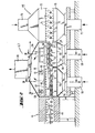
- . figure 1 : une vue d'ensemble en perspective d'un lit de conformation formé de gaines tubulaires tournantes montées sur des tiges cintrées à inclinaison variable, et comportant dans sa dernière partie un dispositif de bombage complémentaire constitué d'un moule en forme de cadre et d'un contre-moule à surface pleine.
- . figure 2 : une coupe longitudinale d'une installation de bombage conforme à l'invention y compris le poste de chauffage et de refroidissement.
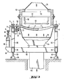
- . figure 3 : une coupe verticale suivant la ligne III - III de la figure 2 montrant le poste de bombage dans sa première partie.
- . figure 4 : une coupe verticale de la partie finale du poste de bombage, suivant la ligne IV - IV de la figure 2.
- . Figure 1: an overall perspective view of a shaping bed formed of rotating tubular sheaths mounted on curved rods with variable inclination, and comprising in its last part an additional bending device consisting of a frame-shaped mold and a solid surface counter mold.
- . Figure 2: a longitudinal section of a bending installation according to the invention including the heating and cooling station.
- . Figure 3: a vertical section along line III - III of Figure 2 showing the bending station in its first part.
- . Figure 4: a vertical section of the final part of the bending station, along the line IV - IV of Figure 2.
La figure 1 illustre la structure de base d'une installation de bombage conforme à l'invention. Toutefois, pour plus de clarté du dessin, le four dans lequel est disposée ladite installation, ainsi que les moyens nécessaires à la production du flux ascendant de gaz chaud dans sa dernière partie, ne sont pas représentés.Figure 1 illustrates the basic structure of a bending installation according to the invention. However, for the sake of clarity of the drawing, the furnace in which said installation is arranged, as well as the means necessary for producing the ascending flow of hot gas in its last part, are not shown.
Dans cette installation, des volumes de verre 1 reposant sur des éléments de conformation tournants constitutifs d'un lit de conformation, sont transportés dans le sens de la flèche F. Ces éléments de conformation tournants sont des gaines tubulaires flexibles 2, tournant sur elles-mêmes autour de tiges cintrées 3. Dans l'exemple de réalisation montré, toutes les tiges cintrées 3 ont la même forme et le même rayon de courbure. Chaque tige cintrée 3 possède deux extrémités 4, redressées par rapport à. la partie médiane cintrée de façon à être dans le prolongement l'une de l'autre, déterminant ainsi un axe de pivotement S - S' autour duquel on peut incliner la tige 3. Les extrémités 4 des tiges 3 sont portées par un chassis constitué de deux poutres longitudinales 6 et 6' et ces extrémités 4 sont libres de pivoter dans des paliers 5 appartenant à ces poutres 6 et 6'. A l'extérieur du chassis 6 - 6' chaque tige cintrée est emmanchée par une des ses extrémités sur une manivelle 8 terminée par un galet 9 qui peut rouler dans un rail à section en U, disposé longitudinalement, c'est à dire dans la direction de progression de volumes de verre 1 représentée par la flèche F, référencé 10 dans une première partie A de l'installation et référencé 11 dans une seconde partie B faisant suite à la première.In this installation,
Ces tiges cintrées sont progressivement de plus en plus inclinées de façon à présenter aux volumes de verre 1 une courbure dans la direction transversale, de plus en plus importante. Ainsi, la première tige cintrée de la partie A, référencée 3' et appartenant au groupe des tiges cintrées 3 est pratiquement couchée dans le plan de transport qui contient les volumes de verre arrivant en amont de l'installation, si bien que la ligne de contact de cette première tige 3' avec les volumes de verre 1 est pratiquement dans ce plan de transport. Au fur et à mesure que l'on progresse dans l'installation, la position angulaire des tiges cintrées 3 se modifie et elles sont de plus en plus inclinées jusqu'à atteindre l'inclinaison maximale au niveau de la dernière tige cintrée 3 de la partie A, tige référencée 3''. Cette inclinaison maximale dépend du rayon de courbure souhaité pour les volumes de verre 1.These bent rods are gradually growing in clinches so as to present glass volumes 1 a curvature in the transverse direction, more and more important. Thus, the first curved rod of part A, referenced 3 ′ and belonging to the group of
Dans notre réalisation le lit de conformation est un lit concave.In our realization the shaping bed is a concave bed.
Pour modifier simultanément la position de l'ensemble des tiges cintrées 3 de façon à leur donner une inclinaison dont l'angle varie progressivement et régulièrement d'une tige à l'autre, le rail 10 est monté inclinable par rapport au plan du chassis 6 - 6'. Pour cela, il est muni d'une articulation 12 lui permettant de pivoter autour d'un axe horizontal Z Z' disposé transversalement en tête de l'installation de bombage. Cette articulation 12 est généralement réglable en hauteur; elle est portée par un bras 13 blocable à la hauteur désirée par rapport à un élément 15 du bâti général, grâce à une vis 14. Un levier 16 appartenant à un mécanisme d'articulation à genouillères 17, 18, 19 décrit plus en détail ci-après, sert à assurer le pivotement du rail 10 autour de l'axe Z Z'. Le rail 11 dans lequel roulent les galets 9 d'extrémité des tiges cintrées 3 dans la partie B de l'installation, s'articule sur un pivot 20 appartenant à l'extrémité aval du rail 10. Il est mobile en hauteur, tout en restant parallèle à lui-même, notamment en restant horizontal, par action sur le levier 16, lequel caman- de la déformation de deux parallélogrammes contigus, le premier formé par une bielle 18, deux biellettes 17 attachées chacune à deux points distants du rail 11, cette portion de rail 11 constituant le quatrième coté, le second formé par la bielle 18 commune aux deux parallèlogram- mes un bras 19 et le levier 16, le quatrième coté étant constitué par une portion de bâti non référencée située entre deux points fixes 21 d'attache d'une part du bras 19 d'autre part du levier 16.To simultaneously modify the position of all the
En raison du déplacement forcément parallèle à lui même, du rail 11, l'inclinaison de toutes les tiges cintrées montées dans la partie B de l'installation de montage et référencées 3'" du fait de leur appartenance à cette partie B, se modifie de la même valeur, de sorte que toutes ces tiges cintrées 3"' ont la même inclinaison, inclinaison identique par ailleurs à celle de la tige cintrée 3", dernière tige cintrée 3 de la partie A du lit de conformation.Due to the displacement necessarily parallel to itself, the
En lieu et place du mécanisme d'articulation à genouillères 16, 17, 18, 19, on pourrait bien entendu utiliser d'autres moyens permettant un réglage en hauteur progressif du rail 11 et une inclinaison progressive du rail 10.Instead of the toggle
Les tiges cintrées 3"' de la partie B du lit de conformation sont montées pivotantes dans un chassis 22 qui s'articule autour des articulations 23 sur l'extrémité aval du chassis 6 - 6' de la partie A du lit de conformation. Ce chassis 22 est monté sur un mécanisme d'articulation à genouillères 24, 25, 26, du même type que celui qui porte le rail 11. Ce mécanisme 24, 25, 26, peut être actionné par un levier 27, ce qui déplace le chassis 22 parallèlement à lui-même dans le sens de la hauteur, et ce qui modifie également l'inclinaison du chassis 6 - 6' de la première partie A du lit de conformation en le faisant pivoter autour des articulations 28, situées en tête de l'installation sur l'axe Z Z'.The
Ainsi grâce à ces réglages on peut sinplement modifier le rayon de courbure du lit de conformation.Thus, thanks to these adjustments, it is possible to modify the radius of curvature of the shaping bed.
Grâce à ces réglages on peut également choisir de conserver au même niveau horizontal soit les bords longitudinaux des volumes de verre, soit la zone proche de l'axe central desdits volumes.Thanks to these adjustments, it is also possible to choose to keep at the same horizontal level either the longitudinal edges of the glass volumes, or the area close to the central axis of said volumes.
Comme déjà signalé, des gaines métalliques tubulaires flexibles 2 résistant à la torsion recouvrent les tiges cintrées 3 et sont entraînées en rotation sur elles-mêmes autour de ces tiges 3, grâce à des pignons dentés 30 dont-elles sont solidaires et qui engrènent sur une ou plusieurs chaînes 31.As already indicated, flexible tubular
Les gaines tubulaires flexibles qui recouvrent également les tiges cintrées 3"' de la portion B du lit de conformation sont référencées 33. Des bagues 34 sont enfilées et fixées sur ces gaines 33. Ces bagues 34 qui peuvent être étroites, ou plus longues et ressembler à de véritables portions de rouleaux cylindriques sont coulissantes sur les gaines 33 dans la direction longitudinale de celles-ci, ce qui permet de les fixer à n'importe quel endroit sur lesdites gaines. Grâce à cet agencement, subsistent entre les gaines 33 et les bagues 34 associées, sous les volumes de verre 1 transportés en appui sur les bagues 34, des espaces dans lesquels se logent les longerons d'un moule 36, en forme de cadre notamment, appartenant à une presse de bombage. Le moule 36 est monté sur un chassis 38 par l'intermédiaire de supports 37, lequel chassis 38 est mobile en hauteur sous l'action de moyens de levage non représentés. Un contre-moule 40, à surface pleine est prévu au dessus du moule inférieur 36 qui peut être soulevé de manière à être pressé contre ledit moule supérieur 40. Ce contre-moule 40 qui n'est représenté que partiellement pour ne pas surcharger la figure, repose par l'intermédiaire d'appuis 41 sur le chassis 22.The flexible tubular sheaths which also cover the
Les tiges cintrées déterminant un lit de conformation concave, le contre-moule 40 est convexe.The curved rods determining a concave conformation bed, the counter-mold 40 is convex.
La figure 2 montre comment une installation de bombage conforme à l'invention et semblable à celle décrite en relation avec la figure 1, est intégrée dans une ligne industrielle de fabrication de vitrages bombés et trempés.Figure 2 shows how a bending installation according to the invention and similar to that described in connection with Figure 1, is integrated in an industrial line for manufacturing curved and toughened glazing.
La ligne complète comprend un four 44 de réchauffage des vo- lunes de verre 1, comportant des rouleaux transporteurs cylindriques 45 entraînés en rotation et des éléments de chauffage 46 grâce auxquels le verre est porté à sa température de bombage, une installation de bombage 47 telle que décrite précédemment en relation avec la figure 1 et un poste de trempe 75.The complete line comprises a
Dans la première partie A de l'installation de bombage, pour plus de clarté du dessin, seuls la poutre 6' du chassis 6 - 6' portant les tiges cintrées 3, lesdites tiges 3 et le rail 10 dans lequel roulent les galets 9 sont représentés. Les mécanismes permettant de régler la position du chassis 6 - 6' ainsi que celle du rail 10 sont amis et ne seront repris que plus loin en relation avec la figure 3.In the first part A of the bending installation, for the sake of clarity of the drawing, only the
Des moyens 48 de chauffage par rayonnement sont prévus dans cette portion A de l'installation de bombage et sont maintenus par des supports 49, 50, 51.Means 48 for radiant heating are provided in this portion A of the bending installation and are held by
En dessous de cette portion A est prévu un soufflage d'air chaud à température d'environ 650°C en vue d'aider à la sustentation des volumes de verre 1.Below this portion A is provided a blowing of hot air at a temperature of about 650 ° C. in order to help the lift of the
Pour cela, une enceinte 54 en forme d'entonnoir alimentée en air chaud par le bas à l'aide d'un conduit d'alimentation 55, recouver- te à sa partie supérieure par une plaque 56 percée de trous disposés régulièrement, est disposée sous cette portion A à distance du chemin emprunté par les volumes de verre 1. Le débit d'air chaud est réglé par des ventilateurs non représentés. Un flux d'air chaud présentant, au niveau de la face inférieure des volumes de verre 1 qui défilent en appui sur les gaines tubulaires 2 recouvrant les tiges cintrées 3, une pression à profil homogène et uniforme, de l'ordre de 2 à 30 mn de colonne d'eau, à composante pratiquement uniquement dynamique, est ainsi créé. Il en résulte la prise en charge par ce flux d'air chaud, d'une partie pouvant être importante du poids des volumes de verre 1.For this, a
D'une manière analogue, en dessous de la portion B du lit de conformation, dans laquelle pour plus de clarté du dessin seuls les gaines tubulaires 33, les bagues 34 prévues sur ces gaines 33, le moule inférieur 36 en forme de cadre ainsi que le contre-moule supérieur 40 sont représentés, est disposée une enceinte 58 en forme d'entonnoir alimentée en air chaud à environ 650°C à sa partie inférieure par un conduit d'alimentation 59. Une plaque perforée 60 ferme cette enceinte 58 à sa partie supérieure et assure la distribution d'un courant d'air chaud vertical, ascendant en direction des volumes de verre 1, qui soit homogène et uniforme au niveau desdits volumes de verre. Ce courant d'air chaud agit en opposition au poids des volumes de verre 1, de sorte que les bagues 34 ne sont que très légèrement chargées par ces volumes de verre -1 et n'ont ainsi aucune influence néfaste.In an analogous manner, below the portion B of the shaping bed, in which for greater clarity of the drawing only the
Au dessus de l'ensemble de ce poste de bombage est monté une botte 64 reliée à un conduit d'évacuation 65, destinée à aspirer les courants d'air chaud émis au travers des plaques perforées 56 et 60.Above the assembly of this bending station is mounted a
Avantageusement, ce gaz chaud récupéré dans le conduit 65 est véhiculé dans des gaines non représentées, recyclé et après réchauffage, ramené dans les enceintes 54 et 58 par les conduits 55 et 59.Advantageously, this hot gas recovered in the
A l'intérieur de la deuxième portion B du lit de conformation sont prévus des détecteurs 67 qui commandent le positionnement correct des volumes de verre 1 entre les deux moules inférieur 36 et supérieur 40 de la presse de bombage. Dès qu'un volume de verre 1 se trouve exactement au-dessus du moule inférieur 36, les moyens de levage du chassis 38 supportant le moule 36 sont actionnés, ce qui a pour effet de presser le volume de verre 1 contre le contre-moule 40 à surface pleine pour lui donner sa forme finale. Le moule inférieur 36 est abaissé et ramené dans sa position initiale dans les espaces ménagés entre les bagues 34. Le volume de verre 1 est de ce fait à nouveau déposé sur les bagues 34 qui tournent et qui le transportent dans le poste de trempe 75 situé en aval.Inside the second portion B of the shaping bed are provided
Dans le poste de trempe 75, le transport des volumes de verre 1 s'effectue de la même manière que dans la première partie A du lit de conformation, c'est à dire sur des gaines tubulaires tournantes 2 en rotation sur elles-mêmes autour de tiges cintrées 3. Sur la figure 2 les moyens de commande des tiges cintrées 3 ne sont pas représentés pour plus de clarté. Le poste de trempe 75 comporte essentiellement un caisson inférieur de soufflage 70 alimenté en air froid sous pression par une conduite d'alimentation 71 et un caisson supérieur 72 alimenté en air froid sous pression par une conduite d'alimentation 73. L'air froid est débité de façon classique par des rampes de buses tubulaires 74 ou des buses à fente et le refroidissement subi par les volumes de verre entraîne leur trempe.In tempering
La structure et le fonctionnement de la ligne de fabrication de vitrages bombés et trempés, en particulier au niveau de la première partie A de l'installation de bombage seront détaillés à nouveau ci-après en relation avec la figure 3.The structure and operation of the production line for curved and toughened glazing, in particular at the level of the first part A of the bending installation will be detailed again below in relation to FIG. 3.
La figure 3 montre les tiges cintrées 3 dont les extrémités alignées 4 tourillonnent dans les paliers 5 appartenant au châssis 6 - 6'. Ces tiges cintrées 3 sont maintenues dans la position angulaire souhaitée par les manivelles équipées des galets 9 engagés dans le rail en U 10. Les gaines tubulaires 2 sont montées sur ces tiges 3 et les pignons dentés 30 solidaires desdites gaines, engrenant sur des roues dentées 32 reliées à des pignons 77 eux-mêmes en prise sur des vis sans fin 78 couplées à un arbre moteur, les entraînent en rotation.FIG. 3 shows the
Le chassis 6 - 6' portant le lit de conformation est monté par des supports 80 sur un cadre 81, 82. Ce cadre 81, 82 est posé sur les tiges 83 de vérins 84 qui permettent un réglage en hauteur.The frame 6 - 6 ′ carrying the shaping bed is mounted by
De façon identique, le rail 10 peut être réglé en hauteur à l'aide d'un vérin 85. Le vérin 85 s'appuie par l'intermédiaire de l'élément d'appui 86 sur le cadre 81, 82 et agit sur le rail 10 par l'intermédiaire de sa tige 87.Similarly, the
Au-dessus des tiges cintrées 3 sont disposés les moyens de chauffage 48 accrochés par les supports 50, 51 à la partie 52 en matière réfractaire de la chambre qui enveloppe la partie A du poste de bombage.Above the
Dans la paroi supérieure de cette structure 52 est ménagée une large ouverture 53 par laquelle l'air chaud aidant à la sustentation des volumes de verre 1, parvient à la hotte d'aspiration 64. Cet air chaud pénètre par le conduit d'alimentation 55 dans l'enceinte 54 en forme d'entonnoir couverte par plaque de distribution perforée 56.In the upper wall of this
La dernière partie B du poste de bambage équipée de la presse de bombage est montrée en détail sur la figure 4. Dans la réalisation particulière montrée, la presse de bombage est prévue pour être changée rapidement en cas de changement du modèle de vitrage fabriqué, la nouvelle presse remise en place ayant la forme du nouveau modèle de vitrages à fabriquer. cette partie B est alors considérée comme une unité interchangeable.The last part B of the bamboo station equipped with the bending press is shown in detail in FIG. 4. In the particular embodiment shown, the bending press is intended to be changed quickly in the event of a change in the glazing model produced, the new press replaced in the form of the new model of glazing to be manufactured. this part B is then considered as an interchangeable unit.
L'ensemble des moyens de bombage de la partie B, c'est à dire les tiges cintrées 3''' revêtues de leurs gaines tubulaires flexibles 33 et de leurs bagues 34, ainsi que les moules inférieur 36 et supérieur 40 de la presse de bombage sont portés par un chassis 88 qui peut être sorti de l'installation par une translation suivant la flèche P et qui se sépare de ladite installation au niveau bas, selon un plan X - X', au niveau haut selon un plan Y-Y',.All the bending means of part B, i.e. the curved rods 3 '' 'coated with their flexible
Lors de l'extraction des moyens de bombage, les galets 9 d'extrémité des manivelles 8 se dégagent aussi du rail 10 en forme de U.During the extraction of the bending means, the
Le chassis 88 est équipé de barres 89 sur lesquelles roule un chariot 90 équipé de roues 92, suivant la direction définie par la double flèche D, sous l'action d'un vérin pneumatique 91. Ce chariot 90 porte des plots 94 munis de fentes obliques, dans lesquelles peuvent coulisser des ergots horizontaux 95 appartenant au chassis 38 porteur du moule inférieur 36. Par action du vérin 91, le chassis 38 est amené à monter ou à descendre, les ergots 95 étant assujettis à glisser dans les fentes obliques des plots 94.The
Le contre-moule 40 est accroché par des pièces 41 à des profilés de support 42 qui sont fixés aux parois latérales 43 de la chambre qui enveloppe la partie B du poste de bombage. Ces parois latérales 43 reposent elles aussi sur le chassis 88, de la même façon que le chassis 98, porteur des paliers 99, dans lesquels tourillonnent les tiges cintrées 3'".The counter-mold 40 is hooked by
Dans cette portion B du poste de bombage, les moyens de production, de distribution et de guidage du courant de gaz aidant à la sustentation des volumes de verre 1 sont particulièrement inportants.In this portion B of the bending station, the means of production, distribution and guiding of the gas stream helping to lift the
On obtient de bons résultats lorsque l'air servant à la sustentation est chauffé par des moyens de chauffage situés en dessous de l'enceinte 58 en forme d'entonnoir, à une température de 620 à 660°C. Dans l'enceinte 58, la surpression est réglée en fonction de la pression désirée au niveau des volumes de verre, celle-ci étant fonction du poids des volumes de verre, et de la fraction de ce poids que l'on désire prendre en charge. Cette pression au niveau du verre est pratiquement uniquement dynamique, et on règle la surpression dans l'enceinte 58 entre 10 et 60 nm de colonne d'eau ( C.E. ) et de préférence entre 15 et 30 mm C.E., par exenple 25 mm C.E. ( soit 250 Pa ). Avec de telles surpressions, on peut constater au niveau du verre des pressions de 2 à 30 mn C.E., capables de prendre en charge de 20 à 80 % du poids des volumes de verre.Good results are obtained when the air used for lifting is heated by heating means located below the
La plaque perforée 60 est située à distance des volumes de verre 1 de façon que la pression ressentie par lesdits volumes de verre soit pratiquement exclusivement dynamique, la composante statique étant négligeable. Des distances de 100 à 250 nm ou 300 mm seront couramment pratiquées.The
Les perforations de la plaque 60 ont un diamètre de 12 à 15mm et sont réparties suivant un pas régulier dans les deux directions transversale et longitudinale, de 25 à 35 mn.The perforations of the
Ainsi les jets d'air sortant des performations se rejoignent et se recouvrent partiellement, fournissant au niveau du verre un flux homogène et uniforme.Thus the air jets leaving the performances meet and partially overlap, providing a uniform and uniform flow at the level of the glass.
Les paramètres de pression, distance, diamètre des perforations sont bien entendu identiques pour la première partie A du poste de bombage.The parameters of pressure, distance, diameter of the perforations are of course identical for the first part A of the bending station.
L'invention décrite vaut également pour des installations de bombage dans lesquelles chaque tige cintrée 3 possède son propre système de réglage d'inclinaison.The invention described also applies to bending installations in which each
L'invention vaut également pour des installations dans lesquelles les tiges 3 ne sont pas toutes identiques, mais présentent des courbures différentes.The invention also applies to installations in which the
De la même façon, la presse de bombage et/ou le système de soufflage d'air chaud pour aider à la sustentation des volumes de verre peuvent être employés dans une installation conférant à la fois une courbure transversale et une courbure longitudinale aux volumes de verre. Dans ce cas les paliers dans lesquels tourillonnent les tiges cintrées ne sont plus alignés, mais disposés sur un chassis courbe dans la direction longitudinale d'avancement des volumes de verre..In the same way, the bending press and / or the hot air blowing system to help lift the glass volumes can be used in an installation conferring both a transverse curvature and a longitudinal curvature to the glass volumes . In this case the bearings in which the curved rods rotate are no longer aligned, but arranged on a curved frame in the longitudinal direction of advancement of the glass volumes.
Claims (13)
Applications Claiming Priority (2)
| Application Number | Priority Date | Filing Date | Title |
|---|---|---|---|
| FR8317829A FR2554436B1 (en) | 1983-11-09 | 1983-11-09 | BOMBING OF GLASS VOLUMES ON CONFORMATION BED CONTAINING ROTATING ELEMENTS |
| FR8317829 | 1983-11-09 |
Publications (3)
| Publication Number | Publication Date |
|---|---|
| EP0143691A2 true EP0143691A2 (en) | 1985-06-05 |
| EP0143691A3 EP0143691A3 (en) | 1985-07-17 |
| EP0143691B1 EP0143691B1 (en) | 1988-02-03 |
Family
ID=9293943
Family Applications (1)
| Application Number | Title | Priority Date | Filing Date |
|---|---|---|---|
| EP84402261A Expired EP0143691B1 (en) | 1983-11-09 | 1984-11-09 | Bending of glass sheets on a continuous forming bed of rotating elements |
Country Status (12)
| Country | Link |
|---|---|
| US (1) | US4557745A (en) |
| EP (1) | EP0143691B1 (en) |
| JP (1) | JPS60171239A (en) |
| KR (1) | KR920005466B1 (en) |
| BR (1) | BR8405697A (en) |
| CA (1) | CA1245452A (en) |
| DE (2) | DE3438705A1 (en) |
| ES (1) | ES8507430A1 (en) |
| FI (1) | FI77010C (en) |
| FR (1) | FR2554436B1 (en) |
| PT (1) | PT79475B (en) |
| YU (1) | YU43939B (en) |
Cited By (10)
| Publication number | Priority date | Publication date | Assignee | Title |
|---|---|---|---|---|
| EP0263030A1 (en) * | 1986-10-01 | 1988-04-06 | Saint-Gobain Vitrage International | Bending and tempering of glass sheets moving on a curved forming bed in the moving direction |
| EP0346200A2 (en) * | 1988-06-08 | 1989-12-13 | Saint-Gobain Vitrage International | Apparatus for producing bent glass sheets |
| EP0404676A1 (en) * | 1989-06-22 | 1990-12-27 | Saint-Gobain Vitrage International | Method and apparatus for bending and tempering by contact |
| EP0436965A1 (en) * | 1990-01-11 | 1991-07-17 | Nippon Sheet Glass Co. Ltd. | Method of and system for pressing sheet glass |
| EP0440776A1 (en) * | 1989-08-29 | 1991-08-14 | Libbey Owens Ford Co | Glass sheet conveying and bending apparatus. |
| EP0477913A2 (en) * | 1990-09-26 | 1992-04-01 | Asahi Glass Company Ltd. | Process and apparatus for bend-shaping glass plates |
| US5139552A (en) * | 1989-12-05 | 1992-08-18 | Nippon Sheet Glass Co., Ltd. | Apparatus for bending and tempering sheet glass |
| EP0555079A1 (en) * | 1992-02-06 | 1993-08-11 | Nippon Sheet Glass Co., Ltd. | Conveyor roll device for preliminarily bending sheet glass |
| EP0634371A1 (en) * | 1993-07-15 | 1995-01-18 | Cristales Automatrices De Jalisco, S.A. | Method and apparatus for three-dimensional forming of plates, in particularly glass-plates |
| US6014873A (en) * | 1990-09-26 | 2000-01-18 | Asahi Glass Company Ltd. | Process for bend-shaping a glass plate and an apparatus for bend-shaping the glass plate |
Families Citing this family (15)
| Publication number | Priority date | Publication date | Assignee | Title |
|---|---|---|---|---|
| BR8807175A (en) * | 1987-07-10 | 1989-10-17 | Libbey Owens Ford Co | APPLIANCE FOR SUPPORTING AND TRANSPORTING GLASS SHEETS |
| US4934514A (en) * | 1987-07-10 | 1990-06-19 | Libbey-Owens-Ford Co. | Conveyor roll construction |
| AU602257B2 (en) * | 1987-08-20 | 1990-10-04 | Libbey-Owens-Ford Co. | Adjustable bearing rail apparatus for bending glass sheets |
| US4799948A (en) * | 1987-08-20 | 1989-01-24 | Libbey-Owens-Ford Co. | Adjustable bearing rail apparatus for bending glass sheets |
| FR2621906B1 (en) * | 1987-10-14 | 1990-01-26 | Saint Gobain Vitrage | IMPROVED GLASS TEMPERING |
| JPH0731999U (en) * | 1994-07-28 | 1995-06-16 | 鹿島建設株式会社 | Through bolt for connecting segments |
| DE69934081T2 (en) | 1998-06-19 | 2007-06-28 | Asahi Glass Co., Ltd. | METHOD AND DEVICE FOR BENDING A GLASS PLATE |
| US6513348B2 (en) | 2001-06-19 | 2003-02-04 | Glasstech, Inc. | Quench station and method for quenching formed glass sheets |
| US6578383B2 (en) * | 2001-06-19 | 2003-06-17 | Glasstech, Inc. | Apparatus and method for roll bending heated glass sheets |
| US6543255B2 (en) * | 2001-06-19 | 2003-04-08 | Glasstech, Inc. | Press bending station and method for job switching |
| FI115768B (en) * | 2003-02-21 | 2005-07-15 | Tamglass Ltd Oy | Method and apparatus for bending and tempering or heat-strengthening a two-way curved glass sheet |
| EP1484291B1 (en) * | 2003-06-04 | 2011-09-14 | Asahi Glass Company, Limited | Method and apparatus for bending a glass sheet using curved rollers. |
| FR2862056B1 (en) * | 2003-11-12 | 2006-01-13 | Saint Gobain | PROCESS AND MACHINE FOR OBTAINING GLAZED GLASS SHEETS |
| TW202041474A (en) * | 2019-01-10 | 2020-11-16 | 美商玻璃技術股份有限公司 | Glass sheet quench arrangement |
| CN114315109B (en) * | 2022-01-14 | 2023-06-23 | 深圳市汇诚装饰工程有限公司 | High-speed centrifugal pressing forming method for curtain wall glass manufacturing |
Citations (4)
| Publication number | Priority date | Publication date | Assignee | Title |
|---|---|---|---|---|
| FR1474251A (en) * | 1966-02-24 | 1967-03-24 | Libbey Owens Ford Glass Co | Method and apparatus for bending glass plates |
| FR2081821A1 (en) * | 1970-03-10 | 1971-12-10 | Ppg Industries Inc | Forming glass sheets |
| FR2342947A1 (en) * | 1976-03-05 | 1977-09-30 | Saint Gobain | METHOD AND DEVICE FOR BOMBING GLASS SHEETS |
| FR2407896A1 (en) * | 1977-11-02 | 1979-06-01 | Ppg Industries Inc | METHOD AND DEVICE FOR FORMING GLASS SHEETS BY ROLLING |
Family Cites Families (6)
| Publication number | Priority date | Publication date | Assignee | Title |
|---|---|---|---|---|
| US3881906A (en) * | 1973-08-20 | 1975-05-06 | Libbey Owens Ford Co | Heat treating glass sheets |
| US3934996A (en) * | 1974-05-02 | 1976-01-27 | Ppg Industries, Inc. | Conveyor rolls on conveyor roll systems for roll forming apparatus |
| US4015968A (en) * | 1975-11-20 | 1977-04-05 | Libbey-Owens-Ford Company | Glass sheet supporting and conveying apparatus |
| US4298368A (en) * | 1979-06-01 | 1981-11-03 | Ppg Industries, Inc. | Delivering and aligning glass sheets in a bending station |
| US4305746A (en) * | 1980-05-01 | 1981-12-15 | Libbey-Owens-Ford Company | Method of and apparatus for bending glass sheets |
| US4376643A (en) * | 1981-09-28 | 1983-03-15 | Ppg Industries, Inc. | Apparatus for conveying glass sheets |
-
1983
- 1983-11-09 FR FR8317829A patent/FR2554436B1/en not_active Expired
-
1984
- 1984-10-23 DE DE3438705A patent/DE3438705A1/en active Granted
- 1984-11-08 BR BR8405697A patent/BR8405697A/en not_active IP Right Cessation
- 1984-11-08 FI FI844400A patent/FI77010C/en not_active IP Right Cessation
- 1984-11-08 PT PT79475A patent/PT79475B/en not_active IP Right Cessation
- 1984-11-08 JP JP59234219A patent/JPS60171239A/en active Pending
- 1984-11-08 KR KR1019840006996A patent/KR920005466B1/en active IP Right Grant
- 1984-11-08 ES ES537492A patent/ES8507430A1/en not_active Expired
- 1984-11-08 YU YU1884/84A patent/YU43939B/en unknown
- 1984-11-09 EP EP84402261A patent/EP0143691B1/en not_active Expired
- 1984-11-09 US US06/669,872 patent/US4557745A/en not_active Expired - Fee Related
- 1984-11-09 CA CA000467510A patent/CA1245452A/en not_active Expired
- 1984-11-09 DE DE8484402261T patent/DE3469165D1/en not_active Expired
Patent Citations (4)
| Publication number | Priority date | Publication date | Assignee | Title |
|---|---|---|---|---|
| FR1474251A (en) * | 1966-02-24 | 1967-03-24 | Libbey Owens Ford Glass Co | Method and apparatus for bending glass plates |
| FR2081821A1 (en) * | 1970-03-10 | 1971-12-10 | Ppg Industries Inc | Forming glass sheets |
| FR2342947A1 (en) * | 1976-03-05 | 1977-09-30 | Saint Gobain | METHOD AND DEVICE FOR BOMBING GLASS SHEETS |
| FR2407896A1 (en) * | 1977-11-02 | 1979-06-01 | Ppg Industries Inc | METHOD AND DEVICE FOR FORMING GLASS SHEETS BY ROLLING |
Cited By (22)
| Publication number | Priority date | Publication date | Assignee | Title |
|---|---|---|---|---|
| FR2604992A1 (en) * | 1986-10-01 | 1988-04-15 | Saint Gobain Vitrage | BOMBING AND TEMPERING OF GLASS PLATES FLAGING ON A CURVED BENDING BED IN THE DIRECTION OF SCROLLING |
| US4820327A (en) * | 1986-10-01 | 1989-04-11 | Saint-Gobain Vitrage | Bending and tempering of glass plates advancing on a shaping bed curved in the direction of advance |
| EP0263030A1 (en) * | 1986-10-01 | 1988-04-06 | Saint-Gobain Vitrage International | Bending and tempering of glass sheets moving on a curved forming bed in the moving direction |
| EP0346200A2 (en) * | 1988-06-08 | 1989-12-13 | Saint-Gobain Vitrage International | Apparatus for producing bent glass sheets |
| EP0346200A3 (en) * | 1988-06-08 | 1990-10-17 | Saint-Gobain Vitrage | Apparatus for producing bent glass sheets |
| EP0404676A1 (en) * | 1989-06-22 | 1990-12-27 | Saint-Gobain Vitrage International | Method and apparatus for bending and tempering by contact |
| FR2648803A1 (en) * | 1989-06-22 | 1990-12-28 | Saint Gobain Vitrage | METHOD AND DEVICE FOR BOMBING AND CONTACT TEMPERATURE |
| TR25572A (en) * | 1989-08-29 | 1993-07-01 | Libbey Owens Ford Co | A layout for transporting and bending glass plates |
| EP0440776A1 (en) * | 1989-08-29 | 1991-08-14 | Libbey Owens Ford Co | Glass sheet conveying and bending apparatus. |
| EP0440776A4 (en) * | 1989-08-29 | 1991-08-28 | Libbey-Owens-Ford Co. | Glass sheet conveying and bending apparatus |
| US5139552A (en) * | 1989-12-05 | 1992-08-18 | Nippon Sheet Glass Co., Ltd. | Apparatus for bending and tempering sheet glass |
| EP0436965A1 (en) * | 1990-01-11 | 1991-07-17 | Nippon Sheet Glass Co. Ltd. | Method of and system for pressing sheet glass |
| EP0477913A2 (en) * | 1990-09-26 | 1992-04-01 | Asahi Glass Company Ltd. | Process and apparatus for bend-shaping glass plates |
| EP0477913A3 (en) * | 1990-09-26 | 1993-04-07 | Asahi Glass Company Ltd. | Process and apparatus for bend-shaping glass plates |
| US6014873A (en) * | 1990-09-26 | 2000-01-18 | Asahi Glass Company Ltd. | Process for bend-shaping a glass plate and an apparatus for bend-shaping the glass plate |
| US6363751B1 (en) * | 1990-09-26 | 2002-04-02 | Asahi Glass Company Ltd. | Apparatus for Bend-shaping a glass plate |
| EP0555079A1 (en) * | 1992-02-06 | 1993-08-11 | Nippon Sheet Glass Co., Ltd. | Conveyor roll device for preliminarily bending sheet glass |
| TR26952A (en) * | 1992-02-06 | 1994-09-12 | Nippon Sheet Glass Co Ltd | Carrier roller assembly for pre-bending glass sheets. |
| US5368625A (en) * | 1992-02-06 | 1994-11-29 | Nippon Sheet Glass Co., Ltd. | Conveyor roll device for preliminarily bending sheet glass |
| EP0719736A2 (en) * | 1992-02-06 | 1996-07-03 | Nippon Sheet Glass Co., Ltd. | Conveyor roll device for preliminarily bending sheet glass |
| EP0719736A3 (en) * | 1992-02-06 | 1996-07-10 | Nippon Sheet Glass Co., Ltd. | Conveyor roll device for preliminarily bending sheet glass |
| EP0634371A1 (en) * | 1993-07-15 | 1995-01-18 | Cristales Automatrices De Jalisco, S.A. | Method and apparatus for three-dimensional forming of plates, in particularly glass-plates |
Also Published As
| Publication number | Publication date |
|---|---|
| FI844400A0 (en) | 1984-11-08 |
| PT79475A (en) | 1984-12-01 |
| FI77010B (en) | 1988-09-30 |
| EP0143691B1 (en) | 1988-02-03 |
| ES537492A0 (en) | 1985-09-16 |
| JPS60171239A (en) | 1985-09-04 |
| YU43939B (en) | 1989-12-31 |
| KR850003878A (en) | 1985-06-29 |
| FR2554436A1 (en) | 1985-05-10 |
| ES8507430A1 (en) | 1985-09-16 |
| BR8405697A (en) | 1985-09-10 |
| CA1245452A (en) | 1988-11-29 |
| KR920005466B1 (en) | 1992-07-04 |
| FR2554436B1 (en) | 1986-01-31 |
| DE3469165D1 (en) | 1988-03-10 |
| DE3438705A1 (en) | 1985-05-23 |
| DE3438705C2 (en) | 1987-05-21 |
| EP0143691A3 (en) | 1985-07-17 |
| FI844400L (en) | 1985-05-10 |
| YU188484A (en) | 1987-10-31 |
| US4557745A (en) | 1985-12-10 |
| PT79475B (en) | 1986-08-05 |
| FI77010C (en) | 1989-01-10 |
Similar Documents
| Publication | Publication Date | Title |
|---|---|---|
| EP0143691B1 (en) | Bending of glass sheets on a continuous forming bed of rotating elements | |
| EP0169770B1 (en) | Method and apparatus for bending glass sheets into a horizontal position | |
| EP0107566B1 (en) | Method of transporting glass sheets brought to their deformation temperature and apparatus therefor | |
| EP0133114B1 (en) | Apparatus for bending and tempering glass sheets | |
| EP0133113B1 (en) | Apparatus with an easily changeable curving unit for bending and tempering glass sheets | |
| EP0255422B1 (en) | Bending of glass sheets | |
| FR2604992A1 (en) | BOMBING AND TEMPERING OF GLASS PLATES FLAGING ON A CURVED BENDING BED IN THE DIRECTION OF SCROLLING | |
| FR2515166A1 (en) | Deformable box mould for shaping glass sheets - has slidable thin plates between flexible opposed sheets | |
| FR2757149A1 (en) | Multi=layered sheet material shaping system | |
| LU81929A1 (en) | METHOD AND DEVICE FOR BOMBING-TEMPERING GLASS SHEETS | |
| EP0148043B1 (en) | Apparatus for bending glass sheets | |
| FR2657046A1 (en) | DEVICE FOR PRESSING ASSEMBLY OF SHEET GLAZING. | |
| EP0484238B1 (en) | Apparatus for bending glass-sheets | |
| FR2572387A1 (en) | FORMING OF CURVED BENDS | |
| EP0884285B1 (en) | Apparatus for bending glass sheets | |
| BE1000065A6 (en) | Method and apparatus for bending glass sheets. | |
| EP0211755A1 (en) | Bending mould with side parts rolling on the glass sheet | |
| FR2609283A1 (en) | APPARATUS AND METHOD FOR PROFILING A SOFT SHEET OF GLASS BY HEATING | |
| EP0310500B1 (en) | Bearing unit for the support rollers in a horizontal furnace, and hotizontal furnace for glass sheets | |
| FR2738811A1 (en) | Flexible press for shaping thermally softened sheet materials | |
| EP0389323B1 (en) | Apparatus for bending and tempering a glass sheet | |
| FR2535705A1 (en) | DEVICE FOR TEMPERING GLASS SHEETS OF DIFFERENT FORMS AND FORMATS | |
| EP0233796A1 (en) | Continuous casting machines | |
| EP0351288B1 (en) | Apparatus for assembling laminated glass | |
| FR2568241A1 (en) | APPARATUS FOR PRESSURIZED BENDING AND TEMPERING OF GLASS SHEETS |
Legal Events
| Date | Code | Title | Description |
|---|---|---|---|
| PUAI | Public reference made under article 153(3) epc to a published international application that has entered the european phase |
Free format text: ORIGINAL CODE: 0009012 |
|
| PUAL | Search report despatched |
Free format text: ORIGINAL CODE: 0009013 |
|
| AK | Designated contracting states |
Designated state(s): BE DE FR GB IT LU NL SE |
|
| AK | Designated contracting states |
Designated state(s): BE DE FR GB IT LU NL SE |
|
| 17P | Request for examination filed |
Effective date: 19851212 |
|
| 17Q | First examination report despatched |
Effective date: 19870204 |
|
| GRAA | (expected) grant |
Free format text: ORIGINAL CODE: 0009210 |
|
| AK | Designated contracting states |
Kind code of ref document: B1 Designated state(s): BE DE FR GB IT LU NL SE |
|
| REF | Corresponds to: |
Ref document number: 3469165 Country of ref document: DE Date of ref document: 19880310 |
|
| GBT | Gb: translation of ep patent filed (gb section 77(6)(a)/1977) | ||
| ITF | It: translation for a ep patent filed |
Owner name: DR. ING. A. RACHELI & C. |
|
| PLBI | Opposition filed |
Free format text: ORIGINAL CODE: 0009260 |
|
| 26 | Opposition filed |
Opponent name: FLACHGLAS AKTIENGESELLSCHAFT Effective date: 19881103 |
|
| NLR1 | Nl: opposition has been filed with the epo |
Opponent name: FLACHGLAS AG |
|
| RAP2 | Party data changed (patent owner data changed or rights of a patent transferred) |
Owner name: VEGLA VEREINIGTE GLASWERKE GMBH Owner name: SAINT-GOBAIN VITRAGE INTERNATIONAL |
|
| NLT2 | Nl: modifications (of names), taken from the european patent patent bulletin |
Owner name: SAINT-GOBAIN VITRAGE INTERNATIONAL TE COURBEVOIE, |
|
| PGFP | Annual fee paid to national office [announced via postgrant information from national office to epo] |
Ref country code: SE Payment date: 19910926 Year of fee payment: 8 |
|
| PGFP | Annual fee paid to national office [announced via postgrant information from national office to epo] |
Ref country code: GB Payment date: 19911024 Year of fee payment: 8 |
|
| PGFP | Annual fee paid to national office [announced via postgrant information from national office to epo] |
Ref country code: FR Payment date: 19911025 Year of fee payment: 8 |
|
| ITTA | It: last paid annual fee | ||
| PGFP | Annual fee paid to national office [announced via postgrant information from national office to epo] |
Ref country code: NL Payment date: 19911130 Year of fee payment: 8 |
|
| PGFP | Annual fee paid to national office [announced via postgrant information from national office to epo] |
Ref country code: DE Payment date: 19920122 Year of fee payment: 8 |
|
| RDAG | Patent revoked |
Free format text: ORIGINAL CODE: 0009271 |
|
| STAA | Information on the status of an ep patent application or granted ep patent |
Free format text: STATUS: PATENT REVOKED |
|
| 27W | Patent revoked |
Effective date: 19920120 |
|
| GBPR | Gb: patent revoked under art. 102 of the ep convention designating the uk as contracting state | ||
| NLR2 | Nl: decision of opposition | ||
| PGFP | Annual fee paid to national office [announced via postgrant information from national office to epo] |
Ref country code: BE Payment date: 19920924 Year of fee payment: 9 |
|
| PGFP | Annual fee paid to national office [announced via postgrant information from national office to epo] |
Ref country code: LU Payment date: 19921001 Year of fee payment: 9 |
|
| EPTA | Lu: last paid annual fee | ||
| EUG | Se: european patent has lapsed |
Ref document number: 84402261.6 Effective date: 19920325 |
|
| APAH | Appeal reference modified |
Free format text: ORIGINAL CODE: EPIDOSCREFNO |