EP0144572A2 - Magnetron-cathodes for the sputtering of ferromagnetic targets - Google Patents
Magnetron-cathodes for the sputtering of ferromagnetic targets Download PDFInfo
- Publication number
- EP0144572A2 EP0144572A2 EP84110940A EP84110940A EP0144572A2 EP 0144572 A2 EP0144572 A2 EP 0144572A2 EP 84110940 A EP84110940 A EP 84110940A EP 84110940 A EP84110940 A EP 84110940A EP 0144572 A2 EP0144572 A2 EP 0144572A2
- Authority
- EP
- European Patent Office
- Prior art keywords
- target
- magnetic poles
- ferromagnetic
- magnetic
- pole
- Prior art date
- Legal status (The legal status is an assumption and is not a legal conclusion. Google has not performed a legal analysis and makes no representation as to the accuracy of the status listed.)
- Granted
Links
- 230000005294 ferromagnetic effect Effects 0.000 title claims abstract description 30
- 238000004544 sputter deposition Methods 0.000 title claims abstract description 15
- 230000005291 magnetic effect Effects 0.000 claims abstract description 112
- 229910052751 metal Inorganic materials 0.000 claims abstract description 23
- 239000002184 metal Substances 0.000 claims abstract description 23
- 239000013077 target material Substances 0.000 claims abstract description 20
- 239000003302 ferromagnetic material Substances 0.000 claims abstract description 14
- 239000002826 coolant Substances 0.000 claims abstract description 8
- 230000004907 flux Effects 0.000 claims description 11
- 230000002093 peripheral effect Effects 0.000 claims description 5
- 238000000889 atomisation Methods 0.000 abstract description 13
- 239000000463 material Substances 0.000 description 16
- 239000000696 magnetic material Substances 0.000 description 9
- 230000000694 effects Effects 0.000 description 7
- 230000003628 erosive effect Effects 0.000 description 7
- 238000000034 method Methods 0.000 description 6
- 230000008569 process Effects 0.000 description 6
- XKRFYHLGVUSROY-UHFFFAOYSA-N Argon Chemical compound [Ar] XKRFYHLGVUSROY-UHFFFAOYSA-N 0.000 description 4
- RYGMFSIKBFXOCR-UHFFFAOYSA-N Copper Chemical compound [Cu] RYGMFSIKBFXOCR-UHFFFAOYSA-N 0.000 description 4
- 230000008859 change Effects 0.000 description 4
- 230000005415 magnetization Effects 0.000 description 4
- XEEYBQQBJWHFJM-UHFFFAOYSA-N Iron Chemical compound [Fe] XEEYBQQBJWHFJM-UHFFFAOYSA-N 0.000 description 3
- 229910052802 copper Inorganic materials 0.000 description 3
- 239000010949 copper Substances 0.000 description 3
- 238000013461 design Methods 0.000 description 3
- 238000005457 optimization Methods 0.000 description 3
- 239000000243 solution Substances 0.000 description 3
- 125000006850 spacer group Chemical group 0.000 description 3
- BGPVFRJUHWVFKM-UHFFFAOYSA-N N1=C2C=CC=CC2=[N+]([O-])C1(CC1)CCC21N=C1C=CC=CC1=[N+]2[O-] Chemical compound N1=C2C=CC=CC2=[N+]([O-])C1(CC1)CCC21N=C1C=CC=CC1=[N+]2[O-] BGPVFRJUHWVFKM-UHFFFAOYSA-N 0.000 description 2
- 229910052786 argon Inorganic materials 0.000 description 2
- 238000009826 distribution Methods 0.000 description 2
- 238000010410 dusting Methods 0.000 description 2
- 230000002349 favourable effect Effects 0.000 description 2
- 239000011810 insulating material Substances 0.000 description 2
- 238000004519 manufacturing process Methods 0.000 description 2
- 230000002829 reductive effect Effects 0.000 description 2
- 239000000758 substrate Substances 0.000 description 2
- 238000012360 testing method Methods 0.000 description 2
- 230000008646 thermal stress Effects 0.000 description 2
- 229910000684 Cobalt-chrome Inorganic materials 0.000 description 1
- 229910000831 Steel Inorganic materials 0.000 description 1
- 229910045601 alloy Inorganic materials 0.000 description 1
- 239000000956 alloy Substances 0.000 description 1
- 229910052782 aluminium Inorganic materials 0.000 description 1
- XAGFODPZIPBFFR-UHFFFAOYSA-N aluminium Chemical compound [Al] XAGFODPZIPBFFR-UHFFFAOYSA-N 0.000 description 1
- 230000004323 axial length Effects 0.000 description 1
- 230000008901 benefit Effects 0.000 description 1
- 239000011248 coating agent Substances 0.000 description 1
- 238000000576 coating method Methods 0.000 description 1
- 239000010952 cobalt-chrome Substances 0.000 description 1
- 238000012937 correction Methods 0.000 description 1
- 230000008878 coupling Effects 0.000 description 1
- 238000010168 coupling process Methods 0.000 description 1
- 238000005859 coupling reaction Methods 0.000 description 1
- 230000003247 decreasing effect Effects 0.000 description 1
- 238000010586 diagram Methods 0.000 description 1
- 238000002474 experimental method Methods 0.000 description 1
- 238000002347 injection Methods 0.000 description 1
- 239000007924 injection Substances 0.000 description 1
- 238000009413 insulation Methods 0.000 description 1
- 239000012212 insulator Substances 0.000 description 1
- 229910052742 iron Inorganic materials 0.000 description 1
- 238000010584 magnetic trap Methods 0.000 description 1
- 230000003287 optical effect Effects 0.000 description 1
- 230000036961 partial effect Effects 0.000 description 1
- 239000002245 particle Substances 0.000 description 1
- 229910000889 permalloy Inorganic materials 0.000 description 1
- 238000004080 punching Methods 0.000 description 1
- 230000002441 reversible effect Effects 0.000 description 1
- 238000000926 separation method Methods 0.000 description 1
- 238000005477 sputtering target Methods 0.000 description 1
- 239000010959 steel Substances 0.000 description 1
Images


Classifications
-
- H—ELECTRICITY
- H01—ELECTRIC ELEMENTS
- H01J—ELECTRIC DISCHARGE TUBES OR DISCHARGE LAMPS
- H01J37/00—Discharge tubes with provision for introducing objects or material to be exposed to the discharge, e.g. for the purpose of examination or processing thereof
- H01J37/32—Gas-filled discharge tubes
- H01J37/34—Gas-filled discharge tubes operating with cathodic sputtering
- H01J37/3411—Constructional aspects of the reactor
- H01J37/3441—Dark space shields
-
- H—ELECTRICITY
- H01—ELECTRIC ELEMENTS
- H01J—ELECTRIC DISCHARGE TUBES OR DISCHARGE LAMPS
- H01J37/00—Discharge tubes with provision for introducing objects or material to be exposed to the discharge, e.g. for the purpose of examination or processing thereof
- H01J37/32—Gas-filled discharge tubes
- H01J37/34—Gas-filled discharge tubes operating with cathodic sputtering
- H01J37/3402—Gas-filled discharge tubes operating with cathodic sputtering using supplementary magnetic fields
- H01J37/3405—Magnetron sputtering
- H01J37/3408—Planar magnetron sputtering
-
- H—ELECTRICITY
- H01—ELECTRIC ELEMENTS
- H01J—ELECTRIC DISCHARGE TUBES OR DISCHARGE LAMPS
- H01J37/00—Discharge tubes with provision for introducing objects or material to be exposed to the discharge, e.g. for the purpose of examination or processing thereof
- H01J37/32—Gas-filled discharge tubes
- H01J37/34—Gas-filled discharge tubes operating with cathodic sputtering
- H01J37/3411—Constructional aspects of the reactor
- H01J37/3414—Targets
- H01J37/3426—Material
-
- H—ELECTRICITY
- H01—ELECTRIC ELEMENTS
- H01J—ELECTRIC DISCHARGE TUBES OR DISCHARGE LAMPS
- H01J37/00—Discharge tubes with provision for introducing objects or material to be exposed to the discharge, e.g. for the purpose of examination or processing thereof
- H01J37/32—Gas-filled discharge tubes
- H01J37/34—Gas-filled discharge tubes operating with cathodic sputtering
- H01J37/3488—Constructional details of particle beam apparatus not otherwise provided for, e.g. arrangement, mounting, housing, environment; special provisions for cleaning or maintenance of the apparatus
- H01J37/3497—Temperature of target
Definitions
- the invention relates to a magnetron cathode for sputtering ferromagnetic targets, consisting of a cathode base body with a magnet system with a yoke and on this circumferentially connected, interlocking magnetic poles of opposite polarity, the pole shoes consisting at least partially of target material with the course of the magnetic poles Similar exit surfaces are assigned, behind which in the depth direction of the arrangement, leaving two circumferential air gaps, a circumferentially connected target made of ferromagnetic metal with an atomizing surface is arranged, the magnetic poles and target not overlapping with respect to their projection surfaces in a plane parallel to the atomizing surface and the pole pieces and the target are connected to one another in an electrically conductive manner.
- Magnetron cathodes with flat or curved atomizing surfaces are well known.
- a spatially defined arrangement of permanent and / or electromagnets is provided in such a position relative to the atomizing surface that a ring-shaped tunnel of magnetic field lines is created above the atomizing surface, through which the glow discharge causing the atomizing process is carried out to an area in the immediate vicinity of the atomizing surface limited, thereby increasing the atomization rate by more than a power of ten.
- Sputtering surface refers to the effective target surface exposed to the glow discharge from which the sputtered particles originate, usually the target front surface (DE-AS 24 31 832).
- magnetron cathodes have become known in several variants, which either have a limited application and / or do not fully meet the expectations placed on them.
- the pole faces of the magnet system are arranged behind the target, so that the majority of the magnetic field lines penetrate the target area twice.
- targets made of magnetic materials e.g. are required for the production of magnetic recording tapes, either not or only usable in connection with additional measures.
- a magnetron cathode is known from US Pat. No. 4,198,283, in which the target, which consists of several sections, is clamped between soft magnetic pole pieces. This essentially fulfills the condition that the projections of targets and pole face do not overlap in a common plane parallel to the atomizing surface. Due to the type of clamping, any air gap parallel to the plane mentioned is avoided. This excludes the use of targets made of ferromagnetic materials, because in such a case the magnetic field lines from the pole pieces in the transverse direction into the target would occur so that there is no longer a magnetic tunnel or the magnetron effect.
- DE-PS 30 12 935 In a magnetron cathode known from DE-PS 30 12 935, the magnetic poles of opposite polarity lie between common planes and each have an endless, self-contained, elongated, round course, which can be described as concentric. The magnetic field lines between the inner and outer poles penetrate the distance between these poles. Within this distance there is a geometrically similar, i.e. oblong-round target arranged from the material to be atomized. However, this arrangement is only suitable for the atomization of non-ferromagnetic material. DE-PS 30 12 935 also describes the possibilities for atomizing ferromagnetic targets with the proviso that a second magnetic field is generated by further magnetic devices.
- this second magnetic field should run such that the tendency of the first magnetic field to penetrate the magnetically permeable sputtering surface is substantially reduced.
- This arrangement is very complex with regard to the additionally required magnet system.
- the degree of utilization of the plate-shaped target material would be extremely poor, so that the known solution for ferromagnetic target material is provided in rod or rod form.
- the unpublished DE-OS 33 16 640 discloses a magnetron cathode, in which the one magnetic pole is arranged behind the central part of the target made of magnetic material. This central part, surrounded by an air gap, is surrounded by a peripheral target part, which to a certain extent has the function of pole pieces. Insofar as the peripheral target part is spatially in front of the central target part, magnetic poles of the same type face each other in the air space in front of the central target part, so that no closed tunnel overlapping the central part can be formed from magnetic field lines.
- the magnetic field lines can therefore only enter the central target part in the area of the one circumferential air gap from the peripheral target part, the maximum atomizing effect occurring in the area of the air gap, in the vicinity of which there is relatively little atomizing material. Even special measures must be taken to ensure that material is not atomized from the bottom of the air gap, which in the case of a non-compatible material would contaminate the deposited layers. With such a solution, essentially only material in the immediate vicinity of the air gap can be atomized, so that the degree of material utilization is very low.
- the magnetic field concentration which is harmful for a flat erosion of the target material and is locally high in the area of the single air gap, is even reinforced by the direct coupling of the target parts to the magnetic poles via highly permeable components.
- the air gaps present at this point may be one Do not exceed a gap of about 1 to 2 mm.
- keeping these air gaps small is only possible in view of the necessary length of the permanent magnets in that the pole shoes are provided with collar-shaped extensions on their inner edges.
- the field lines emerging at the collar ends are guided in a very short way into the target material, from which, following the path of least resistance, they re-enter the opposite poles of the permanent magnets, since the ferromagnetic target, the ferromagnetic support plate and the permanent magnets directly without air gaps sit on top of each other.
- the result is a narrow limitation of the "magnetic trap", so that instead of a flat removal of the target material which is desirable per se, two trench-shaped erosion zones below-the collar edges are the result.
- the arrangement of the collars makes the manufacturing process significantly more expensive, which is disadvantageous insofar as the pole shoes themselves take part in the atomization process, so that the result is only a short service life.
- magnetron cathodes are very popular because of their high specific atomization power, on the other hand, the degree of utilization of the target material is very poor due to the magnetron principle.
- the plasma creates deep erosion trenches in the culmination region of the magnetic field lines, which make the target unusable prematurely.
- DE-PS 25 56 607 discloses that the course of the magnetic field lines is periodically shifted by superimposing a second oscillating magnetic field. From DE-OS 27 07 144 it has become known for the same purpose to periodically shift the magnet system parallel to the atomizing surface.
- the invention is therefore based on the object of improving a magnetron cathode of the type described at the outset in such a way that with it ferromagnetic target materials economically, i.e. can be atomized with high specific atomization performance and with high material utilization.
- the problem is solved in the case of the magnetron cathode described at the outset according to the invention in that the pole shoes are separated from the magnetic poles by a distance “S” in which a non-ferromagnetic medium is located, in that the magnetic poles are in a region which is extends in a manner known per se from a plane going through the atomizing surface of the target in the depth direction of the arrangement and that between the pole shoes and the target on the one hand and the magnetic poles on the other hand a thermally conductive metal body is arranged which is connected to at least one coolant channel and does not consist of one -ferromagnetic material.
- the distance “S” is not necessarily the total distance between the underside of the pole shoes and the magnetic poles (in this total distance there may be ferromagnetic flow guide bodies, for example), but a "gap" located outside of ferromagnetic materials.
- opposite magnetic poles face each other in the air space in front of the annular target or in front of the two air gaps, so that the magnetic field lines can also form a "bridge" over the target. So it is not so, and this is in contrast to DE-OS 32 44 691, that the magnetic field lines in a relatively short way beyond the respective bridged air gap back into the target. occur, from which they flow back into the opposite poles of the permanent magnets with low magnetic resistance.
- this way is equipped with the highest possible magnetic resistance, in that the target and the magnetic poles are arranged in such a way that their projection surfaces do not overlap in a plane parallel to the atomizing surface, but in a particularly advantageous embodiment even lie at intervals "x" and that there is no magnetic, highly conductive connection between target and magnet.
- the proportion of the magnetic flux passing through the target can be varied to the proportion of the flux passing through the target (“bridge”).
- This has a direct influence on the geometric shape of the magnetic field lines and thus the plasma trap and the areal distribution of the target consumption.
- the conditions can be easily optimized, so that the atomizing surface remains approximately level even as the target material continues to be used, so that the result is a target utilization of more than 50%, which far exceeds the state of the art .
- pole shoes are not necessary to provide the pole shoes with a collar with a view to the depth extension of the permanent magnets, so that the pole shoes can be manufactured correspondingly cheaply by removing them from a plate-shaped material. This also eliminates the undesirable conductance of the collar-shaped projections on the magnetic flux.
- magnetron cathode Using the magnetron cathode according to the invention, thick targets made of ferromagnetic materials can be atomized. This possibility is given in particular because magnetic saturation of the target material is not necessary. This is associated with an extremely long service life for the magnetron cathode until the target is changed. Nevertheless, a high atomization speed is possible, which would not be possible with thick ferromagnetic targets without using the device according to the invention.
- the magnet system consists of a defined arrangement of permanent magnets 3 and 4, which are connected to a magnet yoke 5 on their rear side without the interposition of an air gap.
- the direction of magnetization is indicated by the arrows in the permanent magnets, and it can be seen that the permanent magnets 3 and 4 have an opposite magnetization direction, which runs in the direction of the legs 5a and 5b of the magnet yoke 5.
- magnetic poles 3a and 4a are formed which run in a common plane.
- the permanent magnets 3 form a circumferentially connected system that can preferably be composed of individual permanent magnets.
- the axis of which is designated A-A the permanent magnets 3 lie in close succession on the circumference of an annular surface which is formed by the upper side of the leg 5a.
- FIGS. 2 and 3 It will be shown with the aid of FIGS. 2 and 3 that the invention is not limited to a rotationally symmetrical system, but can also be used with so-called oval or rectangular cathodes. However, to simplify the description, the following explanations are given using a rotationally symmetrical system.
- the magnetic yoke 5 has the shape of an "E" in cross section, but is cup-shaped.
- the magnetic poles 3a and 4a form a contiguous arrangement on the circumference, which in the case of FIG. 1 is formed concentrically.
- Such a field line is shown on the right in FIG. 1 and is designated by “M”.
- M Magnetic field line
- annular target 7 which also can be composed of sections. Permanent magnets and targets composed of sections are always referred to as "contiguous on the circumference".
- the surface of the target 7 which is effective for coating purposes is its atomizing surface 7a which is directed upwards or outwards.
- magnetic poles 3a and 4a and target 7 do not overlap in a plane parallel to the atomizing surface 7a, but rather lie within one another with the distances "x" mentioned.
- the target 7 consists of a ferromagnetic material. Without the presence of magnetic pole pieces, this would have the consequence that the magnetic field lines penetrate into the target 7 in the shortest possible way, so that the desired field line course known from non-ferromagnetic targets cannot be achieved via this, as shown in FIG 1, right, represented by the dashed line "M". This means that a so-called magnetron effect cannot develop, so that only the usual, very low atomization rate was achieved, as is known from so-called diode systems.
- the magnetic poles 3a and 4a are now assigned pole shoes 8 and 9, their projection surfaces are a circular surface or a circular surface in a plane parallel to the atomizing surface 7a.
- These pole pieces 8 and 9 consist at least partially, ie on their upward or outward-facing surfaces of the same material as the target 7, and are therefore ferromagnetic.
- the pole pieces are in fact subject, albeit slightly, to an atomization process in the area of their exit surfaces (FIG. 10), so that the material of the pole pieces is also deposited on the substrates. Due to the material identity, this is by no means a disadvantage.
- the target and pole pieces can be produced from one and the same plate of ferromagnetic material, for example by punching or burning out, so that an optimal material utilization is possible.
- atomizing the pole pieces does not involve any shifting of the exit surfaces over time. It has been observed that the atomization of the exit surfaces is largely compensated for by the fact that material dusted by the target is deposited on the exit surfaces of the pole shoes, so that the pole shoes are protected by a dynamic balance between dusting and dusting.
- the atomizing surface 7a lies in the same plane as the surfaces of the magnetic poles 3a and 4a. However, deviations from this position are possible, which can also be used to optimize the system (FIGS. 8 to 10).
- Optimization is understood to mean a design of the system with regard to the highest possible atomization rate while simultaneously removing the target material from the atomization surface 7a as uniformly as possible. Whether these requirements are met can be determined by relatively simple tests: a target 7 is atomized over several hours or days and then the remaining geometry of the target 7 is measured. The above-described change in the distances "x" and "s" relative to one another a correction in the sense shown is possible.
- the overlap can be positive as shown in Figure 1, left, i.e. the projection surfaces overlap on a common plane parallel to the atomizing surface 7a.
- the pole shoes 8 and 9 have outlet surfaces 10 and 11 which are closed on the circumference and whose imaginary generatrix runs perpendicular to the atomizing surface 7a.
- the course of the exit surfaces on their circumference is geometrically similar to the course of the magnetic poles and the target edges, i.e. the distances "x" and the extent of the positive or negative overlap "d" are the same over the entire circumference.
- the target 7 has on both sides of the atomizing surface 7a two cylindrical and therefore circumferential side surfaces 7b and 7c, which generally have the described geometrically similar course, in the special case according to FIG. 1, on the right, but in the projection onto a plane parallel to the atomizing surface 7a the exit surfaces 10 and 11 are congruent.
- FIG. 2 sections of magnetron cathodes with different geometric shapes are shown in the top view of the atomizing surface of the target.
- the target width is indicated with "B" by a double arrow.
- the target 7 and pole pieces 8 and 9 have a positive overlap "d” according to FIG. 1, left and FIG. 5.
- the side surfaces 7b and 7c of the target are covered and only shown in broken lines.
- FIG. 2 half H 1 and H 2 of a magnetron cathode according to FIG. 1 are shown above and below, that is, the union of the two halves H 1 and H 2 leads to a rotationally symmetrical magnetron with the common axis AA according to FIG. 1 the two halves H 1 and H 2 form a rectilinear part T, in which all side surfaces, exit surfaces and air gaps open continuously into the corresponding parts of the rotationally symmetrical halves, so that an elongated magnetron cathode of almost any length dimensions results.
- Such magnetron cathodes can be produced with lengths of approximately 4 m, so that they can also be used to coat large-area substrates such as architecture g las is possible.
- the course of the plasma captured by the magnetic fields corresponds to the course of the target 7, so that the term “racetrack” is also used for the closed area in which the plasma is formed.
- the metal body - as drawn - is meandering in cross section, so that the distances or air gaps described above are maintained. Under "air gaps” such distances within the Understand magnet systems that are filled with non-ferromagnetic materials, such as the insulating material 14/15 and the metal body 16, which may consist of aluminum, .Copper or non-magnetic steel.
- the target 7 and the pole pieces 8/9 are at a relatively high level. Potential and are in electrically conductive connection with the metal body, the two connection ends 17a and 17b of the coolant channel 17 must be passed through the cathode base body 1 with a corresponding insulation distance.
- the target 7 is clamped together with the metal body 16 and the coolant channel 17 against the cathode g round body 1 by a plurality of tension screws 18 distributed over the circumference. This is done with the interposition of a pressure plate 19 which also serves for the connection (not shown) for the cathode voltage. The required voltage is isolated by balgele g te insulator 20 and 21.
- the target 7 has on its back a plurality of jacks 7d, each of which carries a thread for the tension screws 18th
- target 7 and pole pieces 8 and 9 are generally at the same potential (cathode potential), it is also possible to provide a potential difference (relative voltage) between the target on the one hand and pole pieces on the other hand.
- a potential difference relative voltage
- target 7 and pole pieces 8/9 must be isolated from one another. This can be done in a simple manner by interposing further insulating bodies which lie on the metal body 16 at suitable points, which are not indicated separately in FIG. 4.
- FIG. 5 shows in solid lines an arrangement which corresponds to that in FIG. 1, left half.
- the magnetic yoke 5 is enlarged radially with unchanged dimensions of the pole shoes 8/9 and also has a longer leg 5d in the axial direction, the annular surface 5e of which in the same plane E 1 lies in which the upper boundary surfaces of the pole pieces 8/9 are also located.
- a magnet 3b is now attached radially inward to this (circumferential) leg 5d, which corresponds to the magnet 3, but lies opposite the outer cylindrical surface of the pole piece 8. This increases the distance to the target 7, so that a larger proportion of the magnetic flux enters the pole piece 8.
- the overlap "d" is positive in FIG. 5.
- Figure 6 shows an analog arrangement, but with the difference that in this case the overlap "d" is negative is, as has already been described above.
- Such a measure facilitates the removal of the target 7, since this can be removed upwards through the space between the pole pieces 8 and 9. It can also be seen in particular that the two pole pieces 8 and 9 of opposite polarity lie between the same planes E i and E2.
- FIG. 7 again shows an analog arrangement, and likewise with a negative overlap "d".
- a permanent magnet 23 has been stepped in place, which is magnetized radially in accordance with the arrow.
- the pole faces are connected to a cylindrical, ferromagnetic core 24 and to a ferromagnetic hollow cylinder 25, on the upper end faces of which the magnetic poles 4a and 3a are formed.
- the course of the magnetic flux is essentially the same as in the previous embodiments, but the arrangement of the permanent magnet 23 or - with an elongated arrangement of the permanent magnets - is simpler designed. Designs are also conceivable in which the magnet system 2 consists of a piece of a hard magnetic material that is magnetized in a suitable manner.
- the cathode base body 1 is not identical to the magnetic yoke, but is designed as an additional hollow body, and closed by the metal body 16, which is designed here as a plane-parallel plate made of an amagnetic material (copper).
- the seal compared to the cathode base body 1 is effected by unspecified round cord seals and lag screws 27 and 28.
- a coolant channel 17 Between the metal. Body 16 and the cathode base body 1 is a coolant channel 17 in which the permanent magnets 3 and 4 and the magnetic yoke are housed. Fastening is carried out using insulating bodies 27 and lag screws 28.
- the ring-shaped closed target 7 as well as the central pole piece 9 and the peripheral pole pieces 8 are arranged.
- the pole shoes 8 and 9 are attached to spacers 29 and 30, which have a height that is about the width of the air gaps 12 and 13 is greater than the thickness of the target 7. Since this increases the distance between the pole pieces 8 and 9 and the associated magnetic poles of the permanent magnets 3 and 4, the distance between the top of the metal body 16 and the bottom of the pole pieces 8 and 9 is due to ferromagnetic bodies 34 and 35 bridges, which are arranged within the spacers 29 and 30 made of non-magnetic material.
- the outer bodies 34 and the inner bodies 35 are designed as strips, the course of which follows the course of the pole shoes 8.
- the distance "S" is made up of the thickness of the metal body 16 and the distance between the magnetic poles and the inside of the metal body 16. As already explained above, it is important to maintain such a distance, which represents a magnetic resistance of considerable size, with regard to the flow distribution between the target 7 on the one hand and the pole pieces 8 and 9 on the other hand.
- FIG. 8 shows that the projections of the permanent magnets 3 and 4 and of the ferromagnetic bodies 34 and 35 on a common plane parallel to the target surface 7a need not be congruent. Rather, as shown, a considerable lateral offset is possible. This also makes it possible to change the relative proportions of the magnetic flux entering the target 7 on the one hand and the pole shoes 8 and 9 on the other hand, a magnetic short circuit between the ferromagnetic bodies 34 and 35 and the target 7 having to be prevented under all circumstances. For this reason is between the ferromagnetic bodies 34 and 35 and the target 7 each also have a corresponding section of the spacers 29 and 30 made of non-magnetic material.
- FIG. 9 only the target 7 and the pole shoes 8 and 9 above the flat metal body 16 are shown in FIG. 8, and the position of the air gaps 12 and 13 in relation to the atomizing surface 7a can also be seen.
- the axis of the magnetron is labeled "A”, i.e. only the parts of a h a 1 b e n magnetron are shown.
- the course of the horizontal component H of the magnetic field strength is plotted in the upper part of FIG. 9 with exact radial assignment to the axis A, namely the field strength at a distance of 2 mm above the pole shoe surface 8a or 9a. It can be seen that the horizontal component has a maximum in the area of the exit surfaces 10 and 11. However, the curve does not go through zero between the maxima, but even at the location of the minimum, which lies above the center of the target cross section, there is still a considerable horizontal component.
- the course of the curve lying between the two maxima is evidence of the existence of a "bridge" of magnetic field lines F 1 which crosses target 7 and which are present in addition to field lines F 2 directly entering target 7 (FIG. 10). This bridge is the same with that of the previous ones known planar magnetrons existing "magnetic tunnel” comparable. This ensures effective plasma injection in the entire target area, which leads to the extremely flat erosion profile observed (see FIG. 10).
- the ferromagnetic bodies 34 and 35 are also present in the arrangement according to FIG. Attempts to omit the. outer ferromagnetic body 34 have not shown the same favorable result as the tests with an arrangement according to Figure 8.
- the outer ferromagnetic body 34 the magnetic field was in particular in the middle of the target cross section and on the outer target edge significantly increased, so that a more even removal of the target material resulted. This was also reflected in the optical observation of the plasma, which was distributed almost homogeneously over the entire target width at a pressure of 5 x 10 -3 mbar. Based on the atomizing surface 7a, a specific atomizing power of 22.0 w cm -2 was maintained in continuous operation.
- FIG. 10 shows the same parts of the device as hatched in FIG. 9, specifically before the start of the first sputtering process.
- the dashed line shows the location of the Surfaces of the pole shoes 8 and 9 on the one hand and the target 7 on the other hand after the magnetron cathode has been in use for a total of 82 hours. It can be seen that the utilization of the target material is above average evenly over the entire target cross-section and that the feared V-shaped erosion trenches, which occur even when sputtering non-ferromagnetic materials, have not occurred. This process is all the more remarkable since there are no additional aids for the mechanical or electrical movement of the magnetic field.
- FIG. 11 shows a typical magnetron characteristic curve, as was obtained when the magnetron according to FIG. 8 was operated at an argon pressure of 5 ⁇ 10 -3 mbar. From a voltage value of about 400 V, the cathode current I could be increased considerably by a relatively small voltage increase in a linear dependence, which is common for the operation of planar magnetrons with non-ferromagnetic targets. The end point of the characteristic curve shown corresponds to an average power density on the target of 22 W cm -2 .
Abstract
Magnetronkatode zum Zerstäuben ferromagnetischer Targets (7). An einem Katodengrundkörper (1) ist ein Magnetsystem (2) angeordnet, das aus ineinanderliegenden Magnetpolen (3a, 3b) entgegengesetzter Polarität besteht. Zwischen aus Targetmaterial bestehenden Polschuhen (8, 9) und dem Target (7) werden in Tiefenrichtung der Anordnung zwei umlaufende Luftspalte (12, 13) gebildet. Magnetpole (3a, 3b) und Target (7) überschneiden sich in einer Projektionsfläche nicht. Zum Zwecke einer Vergleichmäßigung der Targetabtragung bei gleichzeitig hoher Zerstäubungsrate sind erfindungsgemäß die Polschuhe (8, 9) durch je einen Abstand "S" von den Magnetpolen (3a, 4a) getrennt. Die Magnetpole liegen dabei in einem Bereich, der sich, ausgehend von einer durch die Zerstäubungsfläche (7a) gelegten Ebene in Tiefenrichtung der Anordnung erstreckt. Zwischen den Polschuhen (8, 9) und dem Target (7) einerseits und den Magnetpolen (3a, 4a) andererseits ist ein wärmeleitender Metallkörper angeordnet, der mit mindestens einem Kühlmittelkanal in Verbindung steht und aus einem nicht ferromagnetischen Werkstoff besteht.Magnetron cathode for sputtering ferromagnetic targets (7). A magnet system (2), which consists of magnetic poles (3a, 3b) of opposite polarity lying one inside the other, is arranged on a cathode base body (1). Two circumferential air gaps (12, 13) are formed between pole pieces (8, 9) consisting of target material and the target (7) in the depth direction of the arrangement. Magnetic poles (3a, 3b) and target (7) do not overlap in one projection area. According to the invention, the pole shoes (8, 9) are separated from the magnetic poles (3a, 4a) by a distance "S" for the purpose of making the target removal more uniform and the atomization rate high at the same time. The magnetic poles are located in a region that extends from a plane through the atomizing surface (7a) in the depth direction of the arrangement. A heat-conducting metal body is arranged between the pole shoes (8, 9) and the target (7) on the one hand and the magnetic poles (3a, 4a) on the other hand, which is connected to at least one coolant channel and consists of a non-ferromagnetic material.
Description
Die Erfindung betieht sich auf eine Magnetronkatode zum Zerstäuben ferromagnetischer Targets, bestehend aus einem Katodengrundkörper mit einem Magnetsystem mit einem Joch und auf diesem angeordneten, auf dem Umfang zusammenhängenden, ineinander liegenden Magnetpolen entgegengesetzter Polarität, denen mindestens teilweise aus Targetmaterial bestehende Polschuhe mit dem Verlauf der Magnetpole ähnlichen Austrittflächen zugeordnet sind, hinter denen in Tiefenrichtung der Anordnung unter Belassung zweier umlaufender Luftspalte ein auf dem Umfang zusammenhängendes Target aus ferromagnetischem Metall mit einer Zerstäubungsfläche angeordnet ist, wobei Magnetpole und Target sich hinsichtlich ihrer Projektionsflächen in einer zur Zerstäubungsfläche parallelen Ebene nicht überschneiden und die Polschuhe und das Target elektrisch leitend miteinander verbunden sind.The invention relates to a magnetron cathode for sputtering ferromagnetic targets, consisting of a cathode base body with a magnet system with a yoke and on this circumferentially connected, interlocking magnetic poles of opposite polarity, the pole shoes consisting at least partially of target material with the course of the magnetic poles Similar exit surfaces are assigned, behind which in the depth direction of the arrangement, leaving two circumferential air gaps, a circumferentially connected target made of ferromagnetic metal with an atomizing surface is arranged, the magnetic poles and target not overlapping with respect to their projection surfaces in a plane parallel to the atomizing surface and the pole pieces and the target are connected to one another in an electrically conductive manner.
Magnetronkatoden mit ebenen oder gewölbten Zerstäubungsflächen sind hinreichend bekannt. Dabei wird eine räumlich definierte Anordnung von Permanent- und/oder Elektromagneten in einer Solchen relativen Lage zur Zerstäubungsfläche vorgesehen, daß über der Zerstäubungsfläche ein ringförmig geschlossener Tunnel von Magnetfeldlinien erzeugt wird, durch den die den Zerstäubungsvorgang bewirkende Glimmentladung auf einen Bereich in unmittelbarer Nähe der Zerstäubungsfläche begrenzt und dadurch die Zerstäubungsrate um mehr als eine Zehnerpotenz erhöht wird. Mit "Zerstäubungsfläche" wird die der Glimmentladung ausgesetzte, wirksame Targetoberfläche bezeichnet, von der die zerstäubten Partikel ausgehen, in der Regel also die Targetvorderfläche (DE-AS 24 31 832).Magnetron cathodes with flat or curved atomizing surfaces are well known. A spatially defined arrangement of permanent and / or electromagnets is provided in such a position relative to the atomizing surface that a ring-shaped tunnel of magnetic field lines is created above the atomizing surface, through which the glow discharge causing the atomizing process is carried out to an area in the immediate vicinity of the atomizing surface limited, thereby increasing the atomization rate by more than a power of ten. "Sputtering surface" refers to the effective target surface exposed to the glow discharge from which the sputtered particles originate, usually the target front surface (DE-AS 24 31 832).
Derartige Magnetronkatoden sind in mehreren Varianten bekannt geworden, die entweder eine begrenzte Anwendungsmöglichkeit haben und/oder die in sie gesetzten Erwartungen nicht voll erfüllen. So werden bei der bekannten Ausführungsform die Polflächen des Magnetsystems hinter dem Target angeordnet, so daß die Mehrzahl der Magnetfeldlinien die Targetfläche zweimal durchdringt. Eine solche Bauweise ist jedoch für Targets aus magnetischen Werkstoffen, die z.B. für die Herstellung von magnetischen Aufzeichnungsbändern benötigt werden, entweder nicht oder nur in Verbindung mit zusätziichen Maßnahmen brauchbar.Such magnetron cathodes have become known in several variants, which either have a limited application and / or do not fully meet the expectations placed on them. Thus, in the known embodiment, the pole faces of the magnet system are arranged behind the target, so that the majority of the magnetic field lines penetrate the target area twice. Such a design is, however, for targets made of magnetic materials, e.g. are required for the production of magnetic recording tapes, either not or only usable in connection with additional measures.
Diese Maßnahmen können beispielsweise darin bestehen, das Target sehr dünn auszubilden, so daß eine ausreichende Anzahl von Magnetfeldlinien das Target durchdringen kann. Eine solche Maßnahme.setzt jedoch eine häufige Targeterneuerung voraus. Eine weitere Möglichkeit besteht darin, die Vorrichtung im magnetischen Sättigungsbereich des Targetmaterials zu betreiben, was jedoch außerordentlich starke Magnetsysteme voraussetzt, ohne daß es bisher gelungen wäre, die Verzerrungen des Magnetfeldes in den Griff zu bekommen, die sich mit zunehmendem Verbrauch des Targetmaterials ändern.These measures can consist, for example, of making the target very thin, so that an adequate Number of magnetic field lines that can penetrate the target. However, such a measure requires frequent target renewal. Another possibility is to operate the device in the magnetic saturation region of the target material, which, however, requires extremely strong magnet systems, without which it has so far been possible to get to grips with the distortions of the magnetic field, which change with increasing consumption of the target material.
Weiterhin ist es möglich, das Targetmaterial auf eine Temperatur oberhalb des spezifischen Curie-Punktes zu erhitzen, so daß die magnetischen Feldlinien auch dickere Targetplatten durchdringen können. Die Curie-Temperaturen liegen je nach Targetmaterial zwischen etwa 400 und 1100 °C, so daß erhebliche thermische Probleme mit einer solchen Lösung verbunden sind. Es ist dabei auch bekannt, den Austritt der Feldlinien durch Nuten in der Targetfläche zu erleichtern (US-PS 4 299 678). Eine Unterteilung der Katodenvorderseite in Target und Polschuhe durch Luftspalte ist jedoch nicht vorgesehen, so daß die Wirkung begrenzt und auf die Unterstützung durch Temperaturerhöhung angewiesen ist.It is also possible to heat the target material to a temperature above the specific Curie point, so that the magnetic field lines can also penetrate thicker target plates. Depending on the target material, the Curie temperatures are between approximately 400 and 1100 ° C., so that considerable thermal problems are associated with such a solution. It is also known to facilitate the emergence of the field lines by means of grooves in the target area (US Pat. No. 4,299,678). A subdivision of the front of the cathode into target and pole pieces by air gaps is not provided, however, so that the effect is limited and relies on the support by increasing the temperature.
Durch die US-PS 4 198 283 ist eine Magnetronkatode bekannt, bei der das aus mehreren Teilstücken bestehende Target zwischen weichmaghetischen Polschuhen eingespannt ist. Dadurch ist im wesentlichen die Bedingung erfüllt, daß sich die Projektionen von Targets und Polfläche in eine gemeinsame, zur Zerstäubungsfläche parallele Ebene nicht überschneiden. Durch die Art der Einspannung wird jeglicher Luftspalt parallel zu der genannten Ebene vermieden. Dadurch ist die Verwendung von Targets aus ferromagnetischen Werkstoffen ausgeschlossen, weil nämlich in einem solchen Fall die magnetischen Feldlinien aus den Polschuhen in Querrichtung in das Target eintreten würden, so daß es nicht mehr zur Ausbildung eines magnetischen Tunnels bzw. des Magnetroneffekts kommt.A magnetron cathode is known from US Pat. No. 4,198,283, in which the target, which consists of several sections, is clamped between soft magnetic pole pieces. This essentially fulfills the condition that the projections of targets and pole face do not overlap in a common plane parallel to the atomizing surface. Due to the type of clamping, any air gap parallel to the plane mentioned is avoided. This excludes the use of targets made of ferromagnetic materials, because in such a case the magnetic field lines from the pole pieces in the transverse direction into the target would occur so that there is no longer a magnetic tunnel or the magnetron effect.
Bei einer durch die DE-PS 30 12 935 bekannten Magnetronkatode liegen die Magnetpole entgegengesetzter Polarität zwischen gemeinsamen Ebenen und haben dabei jeweils einen endlosen, in sich geschlossenen länglich-runden Verlauf, der als konzentrisch bezeichnet werden kann. Die Magnetfeldlinien zwischen den inneren und den äußeren Polen durchdringen dabei den Abstand zwischen diesen Polen. Innerhalb dieses Abstandes ist ein geometrisch ähnliches, d.h. länglich-rundes Target aus dem zu zerstäubenden Werkstoff angeordnet. Diese Anordnung ist jedoch ausschließlich für die Zerstäubung nicht-ferromagnetischen Materials geeignet. Die DE-PS 30 12 935 beschreibt auch die Möglichkeiten zur Zerstäubung ferromagnetischer Targets mit der Maß-, gabe, daß durch weitere Magnetvorrichtungen ein zweites Magnetfeld erzeugt wird. Dieses zweite Magnetfeld soll bezüglich des ersten Magnetfeldes und der Zerstäubungsfläche so verlaufen, daß die Neigung des ersten Magnetfeldes wesentlich reduziert wird, die magnetischpermeable Zerstäubungsfläche zu durchdringen. Diese Anordnung ist im Hinblick auf das zusätzlich benötigte Magnetsystem sehr aufwendig. Hinzu kommt, daß der Ausnutzungsgrad des plattenförmigen Targetmaterials extrem schlecht wäre, so daß die bekannte Lösung für ferromagnetisches Targetmaterial in Stangen- oder Stabform vorgesehen ist.In a magnetron cathode known from DE-PS 30 12 935, the magnetic poles of opposite polarity lie between common planes and each have an endless, self-contained, elongated, round course, which can be described as concentric. The magnetic field lines between the inner and outer poles penetrate the distance between these poles. Within this distance there is a geometrically similar, i.e. oblong-round target arranged from the material to be atomized. However, this arrangement is only suitable for the atomization of non-ferromagnetic material. DE-PS 30 12 935 also describes the possibilities for atomizing ferromagnetic targets with the proviso that a second magnetic field is generated by further magnetic devices. With respect to the first magnetic field and the sputtering surface, this second magnetic field should run such that the tendency of the first magnetic field to penetrate the magnetically permeable sputtering surface is substantially reduced. This arrangement is very complex with regard to the additionally required magnet system. In addition, the degree of utilization of the plate-shaped target material would be extremely poor, so that the known solution for ferromagnetic target material is provided in rod or rod form.
Die nicht vorveröffentlichte DE-OS 33 16 640 offenbart eine Magnetronkatode, bei der der eine Magnetpol hinter dem aus magnetischem Werkstoff bestehenden zentralen Teil des Targets angeordnet ist. Dieser zentrale Teil Ist unter Belassung eines Luftspalts von einem peripheren Targetteil umgeben, das in gewissem Umfange die Funktion von Polschuhen hat. Soweit der periphere Targetteil räumlich vor dem zentralen Targetteil liegt, stehen sich im Luftraum vor dem zentralen Targetteil gleichnahmige Magnetpole gegenüber, so daß sich kein den zentralen Teil übergreifender geschlossener Tunnel aus Magnetfeldlinien ausbilden kann. Die Magnetfeldlinien können daher nur im Bereich des einen umlaufenden Luftspalts vom peripheren Targetteil in den zentralen Targetteil eintreten, wobei die maximale Zerstäubungswirkung ausgerechnet im Bereich des Luftspalts auftritt, in dessen Umgebung sich verhältnismäßig wenig Zerstäubungsmaterial befindet. Es muß sogar durch besondere Maßnahmen dafür Sorge getragen werden, daß nicht vom Boden des Luftspalts Material zerstäubt wird, das im Falle eines nicht-kompatiblen Werkstoffs die niedergeschlagenen Schichten verunreinigen wurde. Mit einer derartigen Lösung kann im wesentlichen nur Material in unmittelbarer Nachbarschaft des Luftspalts zerstäubt werden, so daß der Materialausnutzungsgrad sehr gering ist. Die für eine flächige Abtragung des Targetmater.ials schädliche, im Bereich des einzigen Luftspalts örtlich hohe Magnetfeldkonzentration wird durch unmittelbare Ankopplung der Targetteile an die Magnetpole über hochpermeable Bauteile sogar noch verstärkt.The unpublished DE-OS 33 16 640 discloses a magnetron cathode, in which the one magnetic pole is arranged behind the central part of the target made of magnetic material. This central part, surrounded by an air gap, is surrounded by a peripheral target part, which to a certain extent has the function of pole pieces. Insofar as the peripheral target part is spatially in front of the central target part, magnetic poles of the same type face each other in the air space in front of the central target part, so that no closed tunnel overlapping the central part can be formed from magnetic field lines. The magnetic field lines can therefore only enter the central target part in the area of the one circumferential air gap from the peripheral target part, the maximum atomizing effect occurring in the area of the air gap, in the vicinity of which there is relatively little atomizing material. Even special measures must be taken to ensure that material is not atomized from the bottom of the air gap, which in the case of a non-compatible material would contaminate the deposited layers. With such a solution, essentially only material in the immediate vicinity of the air gap can be atomized, so that the degree of material utilization is very low. The magnetic field concentration, which is harmful for a flat erosion of the target material and is locally high in the area of the single air gap, is even reinforced by the direct coupling of the target parts to the magnetic poles via highly permeable components.
Durch die DE-pS 32 44 691 ist eine Magnetronkatode der eingangs beschriebenen Gattung bekannt, bei der die Permanentmagnete auf einer Ebene angeordnet sind, die entweder durch die Zerstäubungsfläche des Targets gebildet wird oder in der die Zerstäubungsfläche zu Beginn des ersten Zerstäubungsvorganges liegt. Bei einer Variante dieses Prinzips liegen die Permanentmagnete in einer Ebene, in der sich die Targetrückseite befindet. In allen Fällen befinden sich die Permanentmagnete in einer Zone höchster thermischer Belastung. Da speziell die heutigen Hochleistungs-Magnetwerkstoffe bereits in einem mit Magnetronkatoden leicht erreichbaren Temperaturbereich zwischen 150 und 200 °C ihre magnetischen Eigenschaften verlieren, wird in der bekannten Schrift angegeben, daß die beschriebene Anordnung äußerst wirksam zu kühlen ist. Da die Permanentmagnete im Hinblick auf die vorgeschriebene Magnetisierungsrichtung eine bestimmte axiale Länge von etwa 8 bis 10 mm nicht unterschreiten können, andererseits aber das Zerstäuben des Magnetwerkstoffs selbst oder seitlich davon angebrachter nicht-ferromagnetischer Blöcke unbedingt unterbleiben muß, dürfen die an dieser Stelle vorhandenen Luftspalte eine Spaltweite von etwa 1 bis 2 mm nicht überschreiten. Die Kleinhaltung dieser Luftspalte ist aber im Hinblick auf die notwendige Länge der Permanentmagnete nur dadurch möglich, daß die Polschuhe an ihren Innenkanten mit kragenförmigen Fortsätzen versehen sind. Die an den Kragenenden austretenden Feldlinien werden auf einem sehr kurzen Wege in das Targetmaterial gelenkt, aus dem sie, dem Weg des geringsten Widerstandes folgend, wieder in die Gegenpole der Permanentmagnete eintreten, da das ferromagnetische Target, die ferromagnetische Stützplatte und die Permanentmagnete ohne Luftspalte direkt aufeinander sitzen. Die Folge ist eine enge Begrenzung der "magnetischen Falle", so daß anstelle einer an sich wünschenswerten flächigen Abtragung des Targetmaterials zwei grabenförmige Erosionszonen unterhalb-der Kragenränder die Folge sind. Durch die Anordnung der Kragen verteuert sich der Herstellprozeß wesentlich, was insofern von Nachteil ist, als die Polschuhe selbst am Zerstäubungsprozeß teilnehmen, so-daß nur eine geringe Standzeit die Folge ist.By DE-P 32 44 691 S magnetron cathode of the above described type is known, in which the permanent magnets are arranged on a plane which is formed either by the sputtering surface of the target or in which the sputtering surface lies at the beginning of the first sputtering process. In a variant of this principle, the permanent magnets lie in a plane in which the rear of the target is located. In all cases, the permanent magnets are located in a zone of extreme thermal stress. Since, in particular, today's high-performance magnetic materials lose their magnetic properties even in a temperature range between 150 and 200 ° C. that is easily accessible with magnetron cathodes, it is stated in the known document that the arrangement described can be cooled extremely effectively. Since the permanent magnets cannot fall short of a certain axial length of about 8 to 10 mm with regard to the prescribed direction of magnetization, but on the other hand the atomization of the magnetic material itself or non-ferromagnetic blocks attached to the side of it must be absolutely avoided, the air gaps present at this point may be one Do not exceed a gap of about 1 to 2 mm. However, keeping these air gaps small is only possible in view of the necessary length of the permanent magnets in that the pole shoes are provided with collar-shaped extensions on their inner edges. The field lines emerging at the collar ends are guided in a very short way into the target material, from which, following the path of least resistance, they re-enter the opposite poles of the permanent magnets, since the ferromagnetic target, the ferromagnetic support plate and the permanent magnets directly without air gaps sit on top of each other. The result is a narrow limitation of the "magnetic trap", so that instead of a flat removal of the target material which is desirable per se, two trench-shaped erosion zones below-the collar edges are the result. The arrangement of the collars makes the manufacturing process significantly more expensive, which is disadvantageous insofar as the pole shoes themselves take part in the atomization process, so that the result is only a short service life.
Einerseits sind Magnetronkatoden wegen ihrer hohen spezifischen Zerstäubungsleistung sehr beliebt, andererseits ist der Ausnutzungsgrad des Targetmaterials aufgrund des Magnetron-Prinzips sehr schlecht. Das Plasma erzeugt nämlich insbesondere im Kulminationsbereich der magnetischen Feldlinien tiefe Erosionsgräben, die das Target vorzeitig unbrauchbar werden lassen. Man hat bereits auf Abhilfe durch Verbreiterung der Erosionsgräben gesonnen: Durch die DE-PS 25 56 607 ist es bekannt, den Verlauf der Magnetfeldlinien durch Oberlagerung eines zweiten oszillierenden Magnetfeldes periodisch zu verlagern. Durch die DE-OS 27 07 144 ist es zum gleichen Zwecke bekannt geworden, das Magnetsystem parallel zur Zerstäubungsfläche periodisch zu verschieben. Schließlich ist es durch die DE-OS 30 04 546 zur Verbesserung des Ausnutzungsgrades des Targetwerkstoffs bereits bekannt, bei einer rotationssymmetrischen Magentronkatode zusätzlich zu dem Hauptmagnetsystem noch mehrere Hilfsmagnetsysteme anzuordnen, durch di.e die nach außen abnehmende Dichte der Feldlinien des Hauptmagnetsystems kompensiert werden soll. Sämtliche zuvor beschriebenen Maßnahmen sind jedoch nur bei Targets aus nicht-ferro. magnetischen Werkstoffen brauchbar, da bei ferromagnetischen Werkstoffen die Magnetfeldlinien das Material von Targets mit wirtsthaftlich hinreichender Dicke nicht durchdringen können.On the one hand, magnetron cathodes are very popular because of their high specific atomization power, on the other hand, the degree of utilization of the target material is very poor due to the magnetron principle. In particular, the plasma creates deep erosion trenches in the culmination region of the magnetic field lines, which make the target unusable prematurely. There has already been a remedy for widening the erosion trenches: DE-PS 25 56 607 discloses that the course of the magnetic field lines is periodically shifted by superimposing a second oscillating magnetic field. From DE-OS 27 07 144 it has become known for the same purpose to periodically shift the magnet system parallel to the atomizing surface. Finally, it is already known from DE-OS 30 04 546 to improve the degree of utilization of the target material to arrange a plurality of auxiliary magnet systems in addition to the main magnet system in the case of a rotationally symmetrical magnetic trench cathode, by means of which the outwardly decreasing density of the field lines of the main magnet system is to be compensated. However, all the measures described above are only for targets made of non-ferro. magnetic materials can be used, since with ferromagnetic materials the magnetic field lines cannot penetrate the material of targets with an economically sufficient thickness.
Der Erfindung liegt daher die Aufgabe zugrunde, eine Magnetronkatode der eingangs beschriebenen Gattung dahingehend zu verbessern,-daß mit ihr ferromagnetische Targetwerkstoffe wirtschaftlich, d.h. mit hoher spezifischer Zerstäubungsleistung und bei hoher Materialausnutzung zerstäubt werden können.The invention is therefore based on the object of improving a magnetron cathode of the type described at the outset in such a way that with it ferromagnetic target materials economically, i.e. can be atomized with high specific atomization performance and with high material utilization.
Die Lösung der gestellten Aufgabe erfolgt bei der eingangs beschriebenen Magnetronkatode erfindungsgemäß dadurch, daß die Polschuhe durch je einen Abstand "S", in dem sich ein nicht ferromagnetisches Medium befindet, von den Magnetpolen getrennt sind, daß die Magnetpole in einem Bereich liegen, der sich in an sich bekannter Weise von einer durch die Zerstäubungsfläche des Targets gehenden Ebene in Tiefenrichtung der Anordnung erstreckt und daß zwischen den Polschuhen und dem Target einerseits und den Magnetpolen andererseits ein wärmeleitender Metallkörper angeordnet ist, der mit mindestens einem Kühlmittelkanal in Verbindung steht und aus einem nicht-ferromagnetischen Werkstoff besteht.The problem is solved in the case of the magnetron cathode described at the outset according to the invention in that the pole shoes are separated from the magnetic poles by a distance “S” in which a non-ferromagnetic medium is located, in that the magnetic poles are in a region which is extends in a manner known per se from a plane going through the atomizing surface of the target in the depth direction of the arrangement and that between the pole shoes and the target on the one hand and the magnetic poles on the other hand a thermally conductive metal body is arranged which is connected to at least one coolant channel and does not consist of one -ferromagnetic material.
Der Abstand "S" ist nicht unbedingt der Gesamtabstand zwischen der Unterseite der Polschuhe und den Magnetpolen (in diesem Gesamtabstand können sich beispielsweise zum Teil ferromagnetische Fließführungskörper befinden), sondern ein außerhalb ferromagnetischer Werkstoffe befindlicher "Spalt".The distance "S" is not necessarily the total distance between the underside of the pole shoes and the magnetic poles (in this total distance there may be ferromagnetic flow guide bodies, for example), but a "gap" located outside of ferromagnetic materials.
Hierbei ist von Bedeutung, daß zwischen den einander gegenüberliegenden Austrittsflächen der Polschuhe und dem Target zwei Luftspalte gebildet werden, die sich in Tiefenrichtung der Anordnung erstrecken. Dabei ist das Target gegenüber den Polschuhen in Tiefenrichtung zurückgesetzt angeordnet, so daß der überwiegende Teil der Magnetfeldlinien über der Zerstäubungsfläche aus den Polschuhen austritt. Diese Maßnahme ist in unmittelbarem Zusammenhang mit der Maßnahme im Oberbegriff zu sehen, daß sich die Projektionen der Magnetpole und des Targets in einer zur Zerstäubungsfläche parallelen Ebene nicht überschneiden, so daß auch an dieser Stelle Luftspalte gebildet werden.It is important here that two air gaps are formed between the opposite exit surfaces of the pole shoes and the target, which extend in the depth direction of the arrangement. The target is set back in relation to the pole pieces in the depth direction, so that the Most of the magnetic field lines emerge from the pole pieces above the atomizing surface. This measure is to be seen in direct connection with the measure in the preamble that the projections of the magnetic poles and the target do not overlap in a plane parallel to the atomizing surface, so that air gaps are also formed at this point.
Von Bedeutung ist hierbei gleichfalls, daß sich im Gegensatz zur OE-OS 33 16 640 - im Luftraum vor dem ringförmigen Target bzw. vor den beiden Luftspalten entgegengesetzte Magnetpole gegenüberliegen, so daß die Magnetfeldlinien auch eine "Brücke" über das Target bilden können. Es ist also nicht so, und dies steht im Gegensatz zur DE-OS 32 44 691, daß die Magnetfeldlinien auf einem relativ kurzen Wege jenseits des jeweils überbrückten Luftspalts wieder in das Target ein- . treten, aus dem sie mit geringem magnetischen Widerstand wieder in die Gegenpole der Permanentmagnete fliessen. Vielmehr wird dieser Weg mit einem möglichst hohen magnetischen Widerstand ausgestattet, indem das Target und die Magnetpole so angeordnet sind, daß sich ihre Projektionsflächen in einer zur Zerstäubungsfläche parallelen Ebene nicht überschneiden, sondern in besonders vorteilhafter Ausführung sogar mit Abständen "x" ineinander liegen und daß keine magnetische hochleitfähige Verbindung zwischen Target und Magneten besteht.It is also important here that, in contrast to OE-OS 33 16 640, opposite magnetic poles face each other in the air space in front of the annular target or in front of the two air gaps, so that the magnetic field lines can also form a "bridge" over the target. So it is not so, and this is in contrast to DE-OS 32 44 691, that the magnetic field lines in a relatively short way beyond the respective bridged air gap back into the target. occur, from which they flow back into the opposite poles of the permanent magnets with low magnetic resistance. Rather, this way is equipped with the highest possible magnetic resistance, in that the target and the magnetic poles are arranged in such a way that their projection surfaces do not overlap in a plane parallel to the atomizing surface, but in a particularly advantageous embodiment even lie at intervals "x" and that there is no magnetic, highly conductive connection between target and magnet.
Der Abstand "S" zwischen den Polschuhen und den Magnetpolen erfüllt in der erfindungsgemäßen Anordnung zwei sehr wichtige Funktionen.
- 1. bewirkt er die thermische Entkopplung der hitzeempfindlichen Permanentmagnete vom heißen Sputtertarget und ermöglicht dadurch sehr hohe Leistungsdichten und dadurch wiederum sehr hohe Sputterraten.
- 2. wirkt er als Luftspalt, und zwar auch dann, wenn der Abstand "S" ganz oder teilweise mit einem nicht-ferromagnetischen Medium wie beispielsweise Kupfer, ausgefüllt sein sollte. Dadurch tritt nicht der gesamte magnetische Fluß in die Polschuhe ein, sondern es entsteht eine Streuwirkung..Ein Teil der magnetischen Feldlinien tritt in die Polschuhe ein, ein weiterer Teil in die Seitenflächen des Targets. Dies hat folgenden Effekt:
- 1. it causes the thermal decoupling of the heat-sensitive permanent magnets from the hot sputtering target and thereby enables very high power densities and in turn very high sputtering rates.
- 2. It acts as an air gap, even if the distance "S" should be completely or partially filled with a non-ferromagnetic medium such as copper. As a result, not all of the magnetic flux enters the pole pieces, but a scattering effect occurs. Some of the magnetic field lines enter the pole pieces, another part into the side surfaces of the target. This has the following effect:
Durch die relative Dimensionierung der in Tiefenrichtung und in Querrichtung angeordneten Luftspalte läßt sich der Anteil des durch das Target verlaufenden magnetischen Flusses zu dem Anteil des über das Target verlaufenden Flusses ("Brücke") variieren. Dies hat wiederum einen unmittelbaren Einfluß auf die geometrische Form der magnetischen Feldlinien und damit der Plasmafalle sowie der flächenmäßigen Verteilung des Targetverbrauchs. Wie noch anhand der Detailbeschreibung näher aufgezeigt werden wird, lassen sich die Verhältnisse leicht optimieren, so daß die Zerstäubungsfläche auch bei fortschreitendem Verbrauch des Targetmaterials'angenähert eben bleibt, so daß'eine den Stand der Technik weit übertreffende Targetausnutzung von über 50 % die Folge ist.Due to the relative dimensioning of the air gaps arranged in the depth direction and in the transverse direction, the proportion of the magnetic flux passing through the target can be varied to the proportion of the flux passing through the target (“bridge”). This in turn has a direct influence on the geometric shape of the magnetic field lines and thus the plasma trap and the areal distribution of the target consumption. As will be shown in more detail on the basis of the detailed description, the conditions can be easily optimized, so that the atomizing surface remains approximately level even as the target material continues to be used, so that the result is a target utilization of more than 50%, which far exceeds the state of the art .
Durch die Unterbringung der Magnetpole in Tiefenrichtung der Anordnung hinter der Zerstäubungsfläche des Targets, insbesondere durch die Unterbringung der Magnetpole hinter dem wärmeleitenden Metallkörper, auf dessen Vorderseite sich Target und Polschuhe befinden, wird erreicht, daß das Magnetsystem nicht nur nicht im Bereich hoher thermischer Belastung angeordnet ist, sondern sogar durch einfache Maßnahmen sehr viel intensiver gekühlt werden kann. Dadurch werden der Auswahl magnetischer Werkstoffe keine Grenzen gesetzt.By accommodating the magnetic poles in the depth direction of the arrangement behind the atomizing surface of the target, in particular by accommodating the magnetic poles behind the thermally conductive metal body, on the front of which there are targets and pole pieces, it is achieved that the magnet system is not only not arranged in the area of high thermal stress is, but can even be cooled much more intensively by simple measures. This will there are no limits to the choice of magnetic materials.
Weiterhin ist es nicht erforderlich, die Polschuhe im Hinblick auf die Tiefenerstreckung der Permanentmagnete mit Kragen zu versehen, so daß sich die Herstellung der Polschuhe durch Heraustrennen aus einem plattenförmigen Werkstoff entsprechend billig gestaltet. Dadurch entfällt gleichzeitig die unerwünschte Leitwirkung der kragenförmigen Vorsprünge auf den magnetischen Fluß.Furthermore, it is not necessary to provide the pole shoes with a collar with a view to the depth extension of the permanent magnets, so that the pole shoes can be manufactured correspondingly cheaply by removing them from a plate-shaped material. This also eliminates the undesirable conductance of the collar-shaped projections on the magnetic flux.
Mittels der erfindungsgemäßen Magnetronkatode lassen sich dicke Targets aus ferromagnetischen Werkstoffen zerstäuben. Diese Möglichkeit ist insbesondere deswegen gegeben, weil eine magnetische Sättigung des Targetmaterials nicht erforderlich ist. Damit verbunden ist eine extrem große Standzeit der Magnetronkatode bis zum Targetwechsel. Dennoch ist eine hohe Zerstäubungsgeschwindigkeit möglich, wie diese bei dicken ferromagnetischen Targets ohne Anwendung der erfindungsgemäßen Vorrichtung nicht möglich wäre.Using the magnetron cathode according to the invention, thick targets made of ferromagnetic materials can be atomized. This possibility is given in particular because magnetic saturation of the target material is not necessary. This is associated with an extremely long service life for the magnetron cathode until the target is changed. Nevertheless, a high atomization speed is possible, which would not be possible with thick ferromagnetic targets without using the device according to the invention.
Weitere vorteilhafte Ausgestaltungen des Erfindungsgegenstandes sind in den Unteransprüchen beschrieben und in der Detailbeschreibung näher erläutert.Further advantageous refinements of the subject matter of the invention are described in the subclaims and explained in more detail in the detailed description.
Ausführungsbeispiele des Erfindungsgegenstandes werden nachfolgend anhand der Figuren 1 bis 11 näher erläutert.
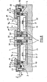
Figur 1 einen schematischen Axialschnitt durch die wesentlichen Teile des Magnetrons,Figuren 2 und 3 Draufsichten auf verschiedene Formen des Magnetrons und ihre Variationsmöglichkeiten,Figur 4 einenAxialschnitt analog Figur 1, jedoch in Vereinigung mit weiteren Bauteilen, d.h. ein spezielles Ausführungsbeispiel,Figur 5 einen schematischen Axialschnitt analog der linkenHälfte von Figur 1 durch ein Magnetron mit einer Variante, bei der die Magnetpole die Polschuhe außen umgeben,Figur 6 einen schematischenAxialschnitt analog Figur 5, jedoch mit negativer Oberlappung "d", undFigur 7 einen schematischenAxialschnitt analog Figur 6, jedoch mit umgekehrter Anordnung von Permanentmagneten,Figur 8 einen Axialschnitt durch eine Variante des des Magnetrons nach Figur 4, bei dem der wärmeleitende Metallkörper zwischen dem Target und dem Magnetsystem als ebene Platte ausgeführt ist,Figur 9 einen Teilausschnitt aus der linken .Hälfte von Figur 8 in vergrößertem Maßstab zusammen mit einem Diagramm, in dem die Horizontal komponente (Hx) der magnetischen Feldstärkeim Abstand von 2 mm Uber der Polschuhoberfläche dargestellt ist, und zwar in Zuordnung zu den radialen Abmessungen des Magnetrons,Figur 10 eineDarstellung analog Figur 9, jedoch mit einem eingezeichneten "Erosionsprofil" (= gestrichelte Linie), undFigur 11 die Betriebskennlinie des Magnetrons nach Figur 8.
- FIG. 1 shows a schematic axial section through the essential parts of the magnetron,
- FIGS. 2 and 3 top views of different forms of the magnetron and their possible variations,
- FIG. 4 shows an axial section analogous to FIG. 1, but in combination with other components, ie a special exemplary embodiment,
- 5 shows a schematic axial section analogous to the left half of FIG. 1 through a magnetron with a variant in which the magnetic poles surround the pole shoes on the outside,
- Figure 6 is a schematic axial section analogous to Figure 5, but with a negative overlap "d", and
- FIG. 7 shows a schematic axial section analogous to FIG. 6, but with the reverse arrangement of permanent magnets,
- FIG. 8 shows an axial section through a variant of the magnetron according to FIG. 4, in which the heat-conducting metal body between the target and the magnet system is designed as a flat plate,
- FIG. 9 shows a partial section from the left half of FIG. 8 on an enlarged scale together with a diagram in which the horizontal component (H x ) of the magnetic field strength is shown at a distance of 2 mm above the pole shoe surface, in association with the radial one Dimensions of the magnetron,
- FIG. 10 shows a representation analogous to FIG. 9, but with a drawn in "erosion profile" (= dashed line), and
- 11 shows the operating characteristic of the magnetron according to FIG. 8.
In Figur 1 ist eine Magnetronkatode mit einem Katodengrundkörper 1 dargestellt, dessen wesentlicher Teil ein Magnetsystem 2 ist. Unter dem Ausdruck "Katodengrundkörper" ist derjenige Teil der Katode zu verstehen, der eine tragende Funktion für die übrigen Bauteile hat und mit dem die Katode Innerhalb einer nicht gezeigten Vakuumkammer befestigt ist. Das Magnetsystem besteht aus einer definierten Anordnung von Permanentmagneten 3 und 4, die auf ihrer Rückseite ohne Zwischenschaltung eines Luftspalts mit einem Magnetjoch 5 verbunden sind. Die Magnetisierungsrichtung ist durch die Pfeile in den Permanentmagneten angedeutet, und es ist erkennbar, daß die Permanentmagnete 3 und 4 eine zueinander entgegengesetzte Magnetisierungsrichtung aufweisen, die in Richtung der Schenkel 5a und 5b des Magnetjochs 5 verläuft. Dadurch werden Magnetpole 3a und 4a gebildet, die in einer gemeinsamen Ebene verlaufen.1 shows a magnetron cathode with a
Die Permanentmagnete 3 bilden dabei ein auf dem Umfang zusammenhängendes System, das bevorzugt aus einzelnen Permanentmagneten zusammengesetzt sein kann. Die Permanentmagnete 3 liegen bei einem rotationssymmetrischen System, dessen Achse A-A bezeichnet ist, in dichter Aneinanderreihung auf dem Umfang einer Kreisringfläche, die durch die Oberseite des Schenkels 5a gebildet wird.The
Es wird anhand der Figuren 2 und 3 noch aufgezeigt werden, daß die Erfindung nicht auf ein rotationssymmetrisches System beschränkt ist, sondern auch bei sogenannten ovalen oder Rechteckkatoden angewandt werden kann. Zur Vereinfachung der Beschreibung werden jedoch die nachfolgenden Erläuterungen anhand eines rotationssymmetrischen Systems gegeben.It will be shown with the aid of FIGS. 2 and 3 that the invention is not limited to a rotationally symmetrical system, but can also be used with so-called oval or rectangular cathodes. However, to simplify the description, the following explanations are given using a rotationally symmetrical system.
Das, Magnetjoch 5 hat im Querschnitt die Form eines "E", Ist jedoch topfförmig ausgebildet. Auf der oberen Stirnfläche des Schenkels 5b ruht der Permanentmagnet 4, der aus einem StUck in Form eines gedrungenen Zylinders bestehen kann. (Bei einer langgestreckten Ausführung gemäß Figur 2 kann jedoch auch der innere Permanentmagnet 4 aus mehreren Teilstücken identischer Magnetisierungsrichtung zusammengesetzt sein).The
Auf die angegebene Weise bilden die Magnetpole 3a und 4a eine auf dem Umfang zusammenhängende Anordnung, die im Fall von Figur 1 konzentrisch aus gebildet ist. Es liegen sich also innen und außen Magnetpole entgegengesetzter Polarität gegenüber, wobei im Falle der Abwesen- heit ferromagnetischer Werkstoffe in der Nähe der Magnetpole Feldlinien senkrecht aus dem einen Magnetpol austreten und nach Durchlaufen einer bogenförmigen Bahn in den jeweils anderen Magnetpol wieder eintreten. Eine solche Feldlinie ist in Figur 1, rechts, dargestellt und mit "M" bezeichnet. Bei Anwesenheit von ferromagnetischen Werkstoffen im Bereich der Magnetpole sind die Verhältnisse jedoch grundlegend anders.In the manner indicated, the
Zwischen den Permanentmagneten 3 und 4 bzw. den damit fluchtenden Schenkeln 5a und 5b liegt ein hohlzylindrischer Raum 6, der nach unten hin durch die obere Kreisringfläche 5c des Magnetjochs 5 gebildet wird. In diesem Raum 6 liegt unter Wahrung zweier seitlicher Abstände "x" ein ebenfalls kreisringförmiges Target 7, das auch aus Teilstücken zusammengesetzt sein kann. Aus Teilstücken zusammengesetzte Permanentmagnete und Targets werden in jedem Falle als "auf dem Umfang zusammenhängend" bezeichnet. Die zu Beschichtungszwecken wirksame Fläche des Targets 7 ist dessen nach oben bzw. außen gerichtete Zerstäubungsfläche 7a.Between the
Aufgrund der gewählten Anordnung bzw. der Einhaltung der Abstände "x" ist die Bedingung erfüllt, daß sich Magnetpole 3a und 4a sowie Target 7 in einer zur Zerstäubungsfläche 7a parallelen Ebene nicht überschneiden, sondern mit den genannten Abständen "x" ineinanderliegen.Due to the chosen arrangement or the observance of the distances "x", the condition is met that
Es ist im vorliegenden Falle wesentlich, daß das Target 7 aus einem ferromagnetischen Werkstoff besteht. Dies hätte ohne das Vorhandensein von magnetischen Polschuhen zur Folge, daß die magnetischen Feldlinien auf dem kürzest möglichen Wege in das Target 7 eindringen, so daß über diesem nicht der gewünschte, von nicht-ferromagnetischen Targets her bekannte Feldlinienverlauf erzielt werden kann, wie er in Figur 1, rechts, durch die gestrichelte Linie "M" dargestellt ist. Damit äber kann sich ein sogenannter Magnetroneffekt nicht ausbilden, so daß auch nur die übliche, sehr niedrige Zerstäubungsrate erreicht wurde, wie sie von sogenannten Dioden-Systemen her bekannt ist.It is essential in the present case that the
Erfindungsgemäß sind nun den Magnetpolen 3a und 4a Polschuhe 8 und 9 zugeordnet, deren Projektionsflächen in eine zur Zerstäubungsfläche 7a parallele Ebene eine Kreisringfläche bzw. eine Kreisfläche sind. Diese Polschuhe 8 und 9 bestehen zumindest teilweise, d.h. an ihren nach oben bzw. außen gerichteten Oberflächen aus dem gleichen Material wie das Target 7, sind also ferromagnetisch. Die Polschuhe unterliegen nämlich - wenn auch geringfügig - einem Zerstäubungsvorgang im Bereich ihrer Austrittsflächen (Figur 10), so daß sich das Material der Polschuhe gleichfalls auf den Substraten niederschlägt. Durch die Materialidentität ist hiermit jedoch keineswegs ein Nachteil verbunden. Im günstigsten Fall können Target und Polschuhe aus ein und derselben Platte ferromagnetischen Materials hergestellt werden, beispielsweise durch Stanzen oder Ausbrennen, so daß eine optimale-Materialausnutzung möglich ist. Mit dem Zerstäuben der Polschuhe ist jedoch im laufe der Zeit keine Verlagerung der Austrittsflächen verbunden. Es wurde nämlich beobachtet, daß die Zerstäubung der Austrittsflächen weitgehend dadurch kompensiert wird, daß vom Target abgestäubtes Material auf den Austrittsflächen der Polschuhe niedergeschlagen wird, so daß ein Schutz der Polschuhe durch ein dynamisches Gleichgewicht zwischen Abstäuben und Aufstäuben eintritt.According to the invention, the
Die Anordnung der Polschuhe 8 und 9 erfolgt in einem Abstand "s" zu den Magnetpolen 3a und 4a, so daß an dieser Stelle eine Eingriffsmöglichkeit für die magnetische Optimierung des Systems gegeben ist. Es hängt nämlich u.a. vom Verhältnis der Abstände x:s ab, welcher Anteil der Magnetfeldlinien von den Magnetpolen 3a bzw. 4a in das Target und welcher Anteil in die Polschuhe 8 und 9 eintritt. Größenordnungsmäßig wird man x=s wählen, wobei beide Abstände im Bereich weniger Millimeter liegen. Vergrößert man den Abstand "s", so dringt ein größerer Anteil des insgesamt von den Permanentmagneten zur Verfugung gestellten magnetischen Flusses an den Rändern des Targets 7 in dieses ein. Verkleinert man hingegen den Abstand "s", so nimmt der Anteil des Flusses zu, der von den Polschuhen 8 und 9 geführt wird.The pole shoes 8 and 9 are arranged at a distance "s" from the
Im vorliegenden Falle liegt die Zerstäubungsfläche 7a in der gleichen Ebene wie die Oberflächen der Magnetpole 3a und 4a. Es sind aber Abweichungen von dieser Lage möglich, die gleichfalls zu einer Optimierung des_Systems benutzt werden können (Figuren 8 bis 10).In the present case, the
Unter Optimierung wird eine Auslegung des Systems im Hinblick auf eine möglichst große Zerstäubungsrate bei gleichzeitiger möglichst gleichförmiger Abtragung des Targetmaterials von der Zerstäubungsfläche 7a verstanden. Ob diese Forderungen erfüllt werden, läßt sich durch verhältnismäßig einfache Versuche feststellen: Man zerstäubt ein Target 7 über mehrere Stunden oder Tage und mißt dann die restliche Geometrie des Targets 7. Durch die vorstehend beschriebene Veränderung der Abstände "x" und "s" relativ zueinander ist eine Korrektur im aufgezeigten Sinne möglich.Optimization is understood to mean a design of the system with regard to the highest possible atomization rate while simultaneously removing the target material from the
Eine weitere Einflußgröße für die Optimierung des Systems ist das Maß der Oberlappung "d". Die Oberlappung kann dabei positiv sein wie in Figur 1, links gezeigt, d.h. die Projektionsflächen auf eine gemeinsame, zur Zerstäubungsfläche 7a parallele Ebene überschneiden sich. Die Oberlappung kann aber auch d=0 sein, wie in Figur 1, rechts, gezeigt; die Oberlappung "d" kann aber auch negativ sein, wie dies in den Figuren 6 und 7 gezeigt ist, d.h. die genannten Projektionsflächen überschneiden sich nicht nur nicht, sie halten auch Abstände voneinander ein. Der in den Figuren 6 und 7 gezeigte Fall einer negativen Oberlappung, selbst wenn sie nur ganz geringfügig ist, hat den Vorteil, daß das Target, welchesAnother factor influencing the optimization of the system is the dimension of the overlap "d". The overlap can be positive as shown in Figure 1, left, i.e. the projection surfaces overlap on a common plane parallel to the
sich wesentlich rascher verbraucht als die Polschuhe, ohne Demontage der Polschuhe ausgewechselt werden kann, wodurch die Stillstandszeiten der Vorrichtung drastisch verkürzt werden.consumes much faster than the pole shoes, can be replaced without dismantling the pole shoes, which drastically shortens the downtimes of the device.
Aufgrund der in Figur 1 dargestellten Anordnung besitzen die Polschuhe 8 und 9 Austrittsflächen 10 und 11, die auf dem Umfang in sich geschlossen sind, und deren gedachte Erzeugende senkrecht zur Zerstäubungsfläche 7a verläuft. Der Verlauf der Austrittsflächen auf ihrem Umfang ist zum Verlauf der Magnetpole und der Targetränder geometrisch ähnlich, d.h. die Abstände "x" sowie das Maß der positiven oder negativen Oberlappung "d" siniauf dem gesamten Umfang gleich. Weiterhin existieren auf jeder Seite der Achse A-A in Tiefenrichtung der Anordnung zwischen dem Target 7 und dem Polschuh 8 einerseits sowie zwischen dem Target 7 und dem Polschuh 9 die beschriebenen zwei Luftspalte 12 und 13, durch die der magnetische Fluß gezwungen ist, zumindest teilweise aus den Autrittsflächen 10 und 11 auszutreten und den weiter oben beschriebenen Verlauf zu nehmen.Because of the arrangement shown in FIG. 1, the
Das Target 7 besitzt auf beiden Seiten der Zerstäubungsfläche 7a zwei zylindrische und daher umlaufende Seitenflächen 7b und 7c, die im allgemeinen den beschriebenen geoemtrisch ähnlichen Verlauf haben, im Sonderfall gemäß Figur 1, rechts, in der Projektion auf eine zur Zerstäubungsfläche 7a parallele Ebene jedoch zu den Austrittsflächen 10 und 11 kongruent sind.The
Anhand von Figur 2 sind - in der Draufsicht auf die Zerstäubungsfläche des Targets 7 Ausschnitte aus Magnetronkatoden mit verschiedenen geometrischen Formen dargestellt. Die Targetbreite ist dabei jeweils mit "B" durch einen Doppelpfeil angegeben. In der linken Hälfte haben Target 7 und Polschuhe 8 bzw. 9 eine positive Oberlappung "d" gemäß Figur 1, links und Figur 5. Infolgedessen sind die Seitenflächen 7b und 7c des Targets verdeckt und nur gestrichelt dargestellt. Im rechten Teil der Figur 2 liegt zwischen Target 7 und den Polschuhen 8 und 9 eine negative Oberlappung gemäß den Figuren 6 und 7 vor, so daß die Seitenflächen 7b und 7c.ebenso sichtbar sind, wie die Austrittsflächen 10 und 11. Diese Art der Darstellung gilt auch für Figur 3.With the aid of FIG. 2, sections of magnetron cathodes with different geometric shapes are shown in the top view of the atomizing surface of the target. The target width is indicated with "B" by a double arrow. In the left half, the
In Figur 2 ist oben und unten jeweils die Hälfte H1 und H2 einer Magnetronkatode nach Figur 1 dargestellt, d.h. die Vereinigung der beiden Hälften H1 und H2 führt zu einem rotationssymmetrischen Magnetron mit der gemeinsamen Achse A-A nach Figur 1. Setzt man zwischen die beiden Hälften H1 und H2 ein geradliniges Teil T ein, bei dem sämtliche Seitenflächen, Austrittsflächen und Luftspalte stufenlos in die entsprechenden Teile der rotationssymmetrischen Hälften einmünden, so ergibt sich eine langgestreckte Magnetronkatode nahezu beliebiger Längenabmessungen. Derartige Magnetronkatoden lassen sich mit Längen von etwa 4m herstellen, so daß mit ihnen auch die Beschichtung von großflächigen Substraten wie beispielsweise Architekturglas möglich ist. Der Verlauf des durch die Magnetfelder eingefangenen Plasmas entspricht dabei dem Verlauf des Targets 7, so daß für den geschlossenen Bereich, in dem sich das Plasma ausbildet, auch der Begriff "Rennbahn" verwendet wird.In FIG. 2, half H 1 and H 2 of a magnetron cathode according to FIG. 1 are shown above and below, that is, the union of the two halves H 1 and H 2 leads to a rotationally symmetrical magnetron with the common axis AA according to FIG. 1 the two halves H 1 and H 2 form a rectilinear part T, in which all side surfaces, exit surfaces and air gaps open continuously into the corresponding parts of the rotationally symmetrical halves, so that an elongated magnetron cathode of almost any length dimensions results. Such magnetron cathodes can be produced with lengths of approximately 4 m, so that they can also be used to coat large-area substrates such as architecture g las is possible. The course of the plasma captured by the magnetic fields corresponds to the course of the
Es ist jedoch nicht erforderlich, die Enden einer langgestreckten Magnetronkatode analog Figur 2 rotationssymmetrisch auszubilden, sondern man kann diese Enden auch rechteckig ausbilden, wie dies in Figur 3 dargestellt ist.However, it is not necessary to form the ends of an elongated magnetron cathode in a rotationally symmetrical manner as in FIG. 2, but these ends can also be formed rectangular, as is shown in FIG. 3.
In Figur 4 sind gleiche Teile wie in Figur 1 mit gleichen Bezugszeichen versehen. Es ist zu erkennen, daß das Magnetsystem 2, insbesondere die Permanentmagnete 3 und 4 mit Isolierstoffumhüllungen 14 und 15 umgeben ist, die eine Potentialtrennung zwischen Target 7 und Polschuhen 8/9 einerseits und dem Katodengrundkörper 1 andererseits bewirken sollen. Zwischen den Polschuhen 8 und 9 sowie dem Target 7 einerseits und den Magnetpolen 3a und 4a mit dem Magnetjoch 5 andererseits ist schließlich noch ein wärmeleitender Metallkörper 16 angeordnet, der mit einem Kühlmittelkanal 17 verbunden ist. Der Kühlmittelkanal 17 besteht aus einem bifilar gewundenen Vierkantrohr, welches flächig auf den Metallkörper 16 aufgelötet ist. Der Metallkörper ist - wie gezeichnet - im Querschnitt mäanderformig ausgebildet, so daß die weiter oben beschriebenen Abstände bzw. Luftspalte eingehalten werden. Unter "Luftspalte" werden auch solche Abstände innerhalb des Magnetsystems verstanden, die durch nicht-ferromagnetische Werkstoffe ausgefüllt sind, wie beispielsweise durch die Isolierstoffumhüllungen 14/15 und den Metallkörper 16, der beispielsweise aus Aluminium,.Kupfer oder amagnetischem Stahl bestehen kann.In Figure 4, the same parts as in Figure 1 are given the same reference numerals. It can be seen that the
Da sich das Target 7 sowie die Polschuhe 8/9 auf einem relativ hohen. Potential befinden und mit dem Metallkörper in elektrisch leitender Verbindung stehen, müssen die beiden Anschlußenden 17a und 17b des Kühlmittelkanals 17 mit entsprechendem Isolationsabstand durch den Katodengrundkörper 1 hindurchgeführt werden.Since the
Das Target 7 wird zusammen mit dem Metallkörper 16 und dem Kühlmittelkanal 17 durch mehrere auf den Umfang verteilte Zugschrauben 18 gegen den Katodengrundkörper 1 verspannt. Dies geschieht unter Zwischenschaltung einer Druckplatte 19, die gleichzeitig zum (nicht gezeigten) Anschluß für die Katodenspannung dient. Die erforderliche Spannungsisolierung erfolgt durch zwischengelegte Isolierkörper 20 und 21. Zum Unterschied von Figur 1 besitzt das Target 7 auf seiner Rückseite mehrere Buchsen 7d, die je ein Gewinde für die Zugschrauben 18 tragen.The
Obwohl Target 7 und Polschuhe 8 bzw. 9 im allgemeinen auf dem gleichen Potential liegen (Katodenpotential), ist es möglich, zwischen Target einerseits und Polschuhen andererseits auch noch eine Potentialdifferenz (Relativspannung) vorzusehen. Zu diesem Zweck ist zwischen der Druckplatte 19, an die die Hauptversorgungsspannung gelegt ist, und den Polschuhen 8 bzw. 9 noch eine weitere Spannungspelle 22 angeordnet, die die gewünschte Potentialdifferenz zwischen 10 und 100 Volt, positiv oder negativ erzeugt. Es versteht sich, daß in diesem Fall Target 7 und Polschuhe 8/9 voneinander isoliert werden müssen. Dies kann auf einfache Weise durch Zwischenschaltung weiterer Isolierkörper geschehen, die an geeigneten Stellen auf dem Metallkörper 16 aufliegen, die in Figur 4 nicht gesondert angedeutet sind.Although
Figur 5 zeigt in ausgezogenen Linien eine Anordnung, die mit derjenigen in Figur 1, linke Hälfte, übereinstimmt. Es ist jedoch links außen eine Variante dargestellt, die folgendes zum Gegenstand hat: Das Magnetjoch 5 ist bei unveränderten Abmessungen der Polschuhe 8/9 radial vergrößert und weist auch in axialer Richtung einen längeren Schenkel 5d auf, dessen Kreisringfläche 5e in der gleichen Ebene E1 liegt, in der auch die oberen Begrenzungsflächen der Polschuhe 8/9 liegen. An diesen (umlaufenden) Schenkel 5d ist nun radial einwärts ein Magnet 3b angesetzt, der dem Magneten 3 entspricht, jedoch der äußeren Zylinderfläche des Polschuhs 8 gegenüberliegt. Hierdurch wird der Abstand zum Target 7 größer, so daß ein größerer Anteil des magnetischen Flusses in den Polschuh 8 eintritt. Die Oberlappung "d" ist in Figur 5 positiv.FIG. 5 shows in solid lines an arrangement which corresponds to that in FIG. 1, left half. However, a variant is shown on the left outside, which has the following object: The
Figur 6 zeigt eine analoge Anordnung, jedoch mit dem Unterschied, daß in diesem Fall die oberlappung "d" negativ ist, wie dies bereits weiter oben beschrieben wurde. Eine solche Maßnahme erleichtert, wie gleichfalls bereits weiter oben beschrieben wurde, den Ausbau des Targets 7, da dies nach oben durch den Zwischenraum zwischen den Polschuhen 8 und 9 hindurch ausgebaut werden kann. Es ist insbesondere auch zu erkennen, daß die beiden Polschuhe 8 und 9 entgegengesetzter Polarität zwischen den gleichen Ebenen Ei und E2 liegen.Figure 6 shows an analog arrangement, but with the difference that in this case the overlap "d" is negative is, as has already been described above. Such a measure, as has also been described above, facilitates the removal of the
Figur 7 zeigt wiederum eine analoge Anordnung, und zwar gleichfalls mit negativer Überlappung "d". Hier wurde jedoch eine Änderung am Magnetsystem 2 vorgenommen, und zwar wurde die Lage des Magnetjochs und der Permanentmagnete vertauscht. In diesem Fall liegt nämlich kein durchgehendes Magnetjoch vor, sondern an dessen Stelle ist ein Permanentmagnet 23 getreten, der nach Maßgabe des Pfeils radial magnetisiert ist. Die Polflächen stehen mit einem zylindrischen, ferromagnetischen Kern 24 sowie mit einem ferromagnetischen Hohlzylinder 25 in Verbindung, an deren oberen Stirnflächen die Magnetpole 4a bzw. 3a gebildet werden. Der Verlauf des magnetischen Flusses ist dabei im wesentlichen der gleiche wie bei den vorangegangenen Ausführungsformen, jedoch ist die Anordnung des Permanentmagnets 23 oder - bei einer langgestreckten Anordnung der Permanentmagnete - einfacher gestaltet. Es sind auch Ausführungen denkbar, in denen das Magnetsystem 2 aus einem StUck eines hartmagnetischen Werkstoffes besteht, das in geeigneter Weise magnetisiert ist.FIG. 7 again shows an analog arrangement, and likewise with a negative overlap "d". Here, however, a change was made to the
Mit den vorstehend beschriebenen Magnetronkatoden wurden Targets aus Eisen mit mittleren Zerstäubungs-raten von etwa 9,0 nm/sec bei einer spezifischen elektrischen Leistung von 25 W/cm2 zerstäubt. Die Targetabtragung war dabei über die gesamte Zerstäubungsfläche 7a außerordentlich gleichmäßig (vergleiche Figur 10). Bei den Versuchen bestanden die Polschuhe und die Targets aus 10 mm dicken Weicheisenteilen, in denen der magnetische Fluß weit unterhalb der magnetischen Sättigung lag. Die Zerstäubungsatmosphäre bestand aus Argon mit einem Druck zwischen 8 x 10⁻⁴ und 10-2 mbar. Weitere mögliche Werkstoffe sind z.B.: Permalloy, CoCr-Legierung (z.B. 80/20).Were netronkatoden g of the above described Ma targets of iron with average Zerstäubun g s-rates of about 9.0 nm / sec at a specific electrical power of 25 W / cm 2 atomized. The target removal was extremely uniform over the
In Figur 8 sind gleiche Teile oder Teile mit gleichen Funktionen mit den gleichen Bezugszeichen wie bisher versehen. In dem hier dargestellten Fall ist der Katodengrundkörper 1 nicht mit dem Magnetjoch identisch, sondern als zusätzlicher Hohlkörper ausgebildet, und durch den Metallkörper 16 verschlossen, der hier als planparallele Platte aus einem amagnetischen Werkstoff (Kupfer) ausgeführt ist. Die Abdichtung gegenüber dem Katodengrundkörper 1 wird durch nicht näher bezeichnete Rundschnurdichtungen und Zugschrauben 27 und 28 bewirkt. Zwischen dem Metall- . körper 16 und dem Katodengrundkörper 1 befindet sich ein Kühlmittelkanal 17, in dem die Permanentmagnete 3 und 4 sowie das Magnetjoch untergebracht sind. Die Befestigung erfolgt über Isolierkörper 27 und Zugschrauben 28.In Figure 8, the same parts or parts with the same functions are provided with the same reference numerals as before. In the case shown here, the
Auf der ebenen Außenseite des Metallkörpers 16 sind das ringförmigegeschlossene Target 7 sowie der zentrale Polschuh 9 und die peripheren Polschuhe 8 angeordnet. Um hierbei die beiden Luftspalte 12 und 13, die dem Verlauf der Targetränder folgen, in Tiefenrichtung des Magnetrons zu erhalten, sind die Polschuhe 8 und 9 auf Distanzstücken 29 und 30 befestigt, die eine Höhe aufweisen, die um die Breite der Luftspalte 12 und 13 größer ist als die Dicke des Targets 7. Da hierdurch der Abstand zwischen den Polschuhen 8 und 9 und den zugehörigen Magnetpolen der Permanentmagnete 3 und 4 wächst, wird der Abstand zwischen der Oberseite des Metallkörpers 16 und der Unterseite der Polschuhe 8 und 9 durch ferromagnetische Körper 34 und 35 überbrückt, die innerhalb der aus amagnetischem Werkstoff bestehenden Distanzstücke 29 und 30 angeordnet sind. Die äußeren Körper 34 und die inneren Körper 35 sind im Falle von Rechteckkatoden als Leisten ausgeführt, deren Verlauf dem Verlauf der Polschuhe 8 folgt.On the flat outside of the
Es ist Figur 8 zu entnehmen, daß der Abstand "S" sich aus der Dicke des Metallkörpers 16 und aus dem Abstand zusammensetzt, der zwischen den Magnetpolen und der Innenseite des Metallkörpers 16 besteht. Wie bereits weiter oben ausgeführt wurde, ist die Einhaltung eines solchen Abstandes, der einen magnetischen Widerstand von beträchtlicher Größe darstellt, im Hinblick auf.die Flußverteilung zwischen dem Target 7 einerseits und den Polschuhen 8 und 9 andererseits wichtig.It can be seen from FIG. 8 that the distance "S" is made up of the thickness of the
Figur 8 ist zu entnehmen, daß die Projektionen der Permanentmagnete 3 und 4 und der ferromagnetischen Körper 34 und 35 auf eine gemeinsame, zur Targetfläche 7a parallele Ebene, nicht kongruent sein müssen. Vielmehr ist - wie gezeigt - ein erheblicher seitlicher Versatz möglich. Auch hierdurch lassen sich die relativen Anteile des in das Target 7 einerseits und in die Polschuhe 8 bzw. 9 andererseits eintretenden magnetischen Flusses verändern, wobei ein magnetischer Kurzschluß zwischen den ferromagnetischen Körpern 34 und 35 und dem Target 7 unter allen Umständen verhindert werden muß. Aus diesem Grunde befindet sich zwischen den ferromagnetischen Körpern 34 und 35 und dem Target 7 auch jeweils noch ein entsprechender Abschnitt der aus amagnetischem Werkstoff bestehenden Distanzstücke 29 und 30.FIG. 8 shows that the projections of the
In Figur 9 sind aus Figur 8 nur noch das Target 7 und die Polschuhe 8 bzw. 9 oberhalb des ebenen Metallkörpers 16 dargestellt, und auch die Lage der Luftspalte 12 und 13 ist in Relation zur Zerstäubungsfläche 7a erkennbar. Die Achse des Magnetrons ist mit "A" bezeichnet, d.h. es sind nur die Teile eines h a 1 b e n Magnetrons dargestellt.In FIG. 9, only the
Unter exakter radialer Zuordnung zur Achse A ist im oberen Teil von Figur 9 der Verlauf der Horizontalkomponente H der magnetischen Feldstärke aufgetragen, und zwar handelt es sich um die Feldstärke im Abstand von 2 mm über der Polschuhoberfläche 8a bzw. 9a. Es ist zu erkennen, daß die Horizontalkomponente im Bereich der Austrittsflächen 10 und 11 je ein Maximum aufweist. Zwischen den Maxima geht die Kurve jedoch keineswegs durch Null, sondern selbst an der Stelledes Minimums, das über der Mitte des Targetquerschnitts liegt, ist noch eine erhebliche Horizontalkomponente vorhanden. Der zwischen den beiden Maxima liegende Verlauf der Kurve ist ein Beweis für die Existenz einer das Target 7 übergreifenden "Brücke" aus magnetischen Feldlinien F1, die zusätzlich zu den unmittelbar in das Target 7 eintretenden Feldlinien F2 vorhanden sind (Figur 10). Diese Brücke ist mit dem bei den bisher bekannten planaren Magnetrons vorhandenen "magnetischen Tunnel" vergleichbar. Hierdurch ist ein effektiver Plasmaeinschuß im gesamten Targetbereich gewährleistet, was zu dem beobachteten, extrem flachen Erosionsprofil führt (vergleiche Figur 10).The course of the horizontal component H of the magnetic field strength is plotted in the upper part of FIG. 9 with exact radial assignment to the axis A, namely the field strength at a distance of 2 mm above the
Es ist hervorzuheben, daß auch bei der Anordnung gemäß Figur 9 die ferromagnetischen Körper 34 und 35 vorhanden sind. Versuche, die unter Weglassung der . äußeren ferromagnetischen Körper 34 durchgeführt worden sind, zeigen nicht das gleiche günstige Ergebnis wie die Versuche mit einer Anordnung gemäß Figur 8. Durch die äußeren ferromagnetischen Körper 34 wurde jedenfalls das Magnetfeld insbesondere in der Mitte des Targetquerschnitts und am äußeren Targetrand deutlich verstärkt, so daß sich eine gleichmäßigere Abtragung des Targetmaterials ergab. Dies äußerte sich auch bei der optischen Beobachtung des Plasmas, das bei einem Druck von 5 x 10⁻³ mbar fast homogen über die gesamte Targetbreite verteilt war. Bezogen auf die Zerstäubungsfläche 7a wurde eine spezifische Zerstäubungsleistung von 22,0 w cm-2 im Dauerbetrieb aufrecht erhalten.It should be emphasized that the
In Figur 10 sind die gleichen Vorrichtungsteile wie in Figur 9 schraffiert dargestellt, und zwar vor Beginn des ersten 2erstäubungsvorganges. Die gestrichelt eingezeichnete Linie zeigt die Lage der Oberflächen der Polschuhe 8 und 9 einerseits und des Targets 7 andererseits, nachdem die Magnetronkatode für die Dauer von insgesamt 82 Stunden im Einsatz gewesen ist. Es zeigt sich, daß die Ausnutzung des Targetwerkstoffs nahezu Uber den gesamten Targetquerschnitt überdurchschnittlich gleichmäßig ist und daß es insbesondere nicht zu den gefürchteten V-förmigen Erosionsgräben gekommen ist, wie sie sich selbst beim Zerstäuben von nicht-ferromagnetischen Werkstoffen einstellen. Dieser Vorgang ist um so bemerkenswerter, als hier keine zusätzlichen Hilfsmittel für die mechanische oder elektrische Bewegung des Magnetfeldes vorhanden sind.FIG. 10 shows the same parts of the device as hatched in FIG. 9, specifically before the start of the first sputtering process. The dashed line shows the location of the Surfaces of the
Figur 11 zeigt eine typische Magnetronkennlinie, wie sie beim Betrieb des Magnetrons nach Figur 8 bei einem Argon Druck von 5 x 10⁻³ mbar erhalten wurde. Ab einem Spannungswert von etwa 400 V ließ sich der Katodenstrom I durch eine relativ geringe Spannungserhöhung in linearer Abhängigkeit beträchtlich steigern, was für den Betrieb von Planarmagnetrons mit nicht-ferromagnetischen Targets üblich ist. Der Endpunkt der gezeigten Kennlinie entspricht einer mittleren Leistungsdichte am Target von 22 W cm-2.FIG. 11 shows a typical magnetron characteristic curve, as was obtained when the magnetron according to FIG. 8 was operated at an argon pressure of 5 × 10 -3 mbar. From a voltage value of about 400 V, the cathode current I could be increased considerably by a relatively small voltage increase in a linear dependence, which is common for the operation of planar magnetrons with non-ferromagnetic targets. The end point of the characteristic curve shown corresponds to an average power density on the target of 22 W cm -2 .
Claims (8)
Priority Applications (1)
| Application Number | Priority Date | Filing Date | Title |
|---|---|---|---|
| AT84110940T ATE47504T1 (en) | 1983-12-05 | 1984-09-13 | MAGNETRON CATODE FOR ATOMY FERROMAGNETIC TARGETS. |
Applications Claiming Priority (2)
| Application Number | Priority Date | Filing Date | Title |
|---|---|---|---|
| DE3343904 | 1983-12-05 | ||
| DE3343904 | 1983-12-05 |
Publications (3)
| Publication Number | Publication Date |
|---|---|
| EP0144572A2 true EP0144572A2 (en) | 1985-06-19 |
| EP0144572A3 EP0144572A3 (en) | 1986-07-30 |
| EP0144572B1 EP0144572B1 (en) | 1989-10-18 |
Family
ID=6216066
Family Applications (1)
| Application Number | Title | Priority Date | Filing Date |
|---|---|---|---|
| EP84110940A Expired EP0144572B1 (en) | 1983-12-05 | 1984-09-13 | Magnetron-cathodes for the sputtering of ferromagnetic targets |
Country Status (6)
| Country | Link |
|---|---|
| US (1) | US4572776A (en) |
| EP (1) | EP0144572B1 (en) |
| JP (1) | JPS60138070A (en) |
| KR (1) | KR910009249B1 (en) |
| AT (1) | ATE47504T1 (en) |
| DE (1) | DE3480245D1 (en) |
Cited By (6)
| Publication number | Priority date | Publication date | Assignee | Title |
|---|---|---|---|---|
| EP0187226A2 (en) * | 1984-11-14 | 1986-07-16 | Hitachi, Ltd. | Sputtering apparatus with film forming directivity |
| DE3601439C1 (en) * | 1986-01-20 | 1987-04-09 | Glyco Metall Werke | Layered composite material, in particular for sliding and friction elements, and method for its production |
| EP0334347A1 (en) * | 1988-03-25 | 1989-09-27 | ELAN Elektronische Anlagen GmbH | Cathode sputtering device |
| DE4000941A1 (en) * | 1989-01-20 | 1990-08-02 | Ulvac Corp | Magnetron vaporising system - includes magnetic circuit in plasma-producing vaporiser giving more even target consumption in plasma-coating system |
| DE19648390A1 (en) * | 1995-09-27 | 1998-05-28 | Leybold Materials Gmbh | Target for the sputter cathode of a vacuum coating plant |
| EP4283011A1 (en) * | 2022-05-26 | 2023-11-29 | Instytut Fizyki Polskiej Akademii Nauk | Magnetron device for sputtering target |
Families Citing this family (41)
| Publication number | Priority date | Publication date | Assignee | Title |
|---|---|---|---|---|
| JPH0689443B2 (en) * | 1984-11-14 | 1994-11-09 | 株式会社日立製作所 | Target for spattering |
| DE3527626A1 (en) * | 1985-08-01 | 1987-02-05 | Leybold Heraeus Gmbh & Co Kg | SPRAYING CATODE ACCORDING TO THE MAGNETRON PRINCIPLE |
| US4855033A (en) * | 1986-04-04 | 1989-08-08 | Materials Research Corporation | Cathode and target design for a sputter coating apparatus |
| EP0240369B1 (en) * | 1986-04-04 | 1993-09-15 | Materials Research Corporation | Improved cathode and target design for a sputter coating apparatus |
| DE3624150C2 (en) * | 1986-07-17 | 1994-02-24 | Leybold Ag | Atomizing cathode based on the magnetron principle |
| JPH07107188B2 (en) * | 1986-09-12 | 1995-11-15 | 松下電器産業株式会社 | Sputtering target |
| US4865708A (en) * | 1988-11-14 | 1989-09-12 | Vac-Tec Systems, Inc. | Magnetron sputtering cathode |
| US4892633A (en) * | 1988-11-14 | 1990-01-09 | Vac-Tec Systems, Inc. | Magnetron sputtering cathode |
| JPH02243761A (en) * | 1989-03-15 | 1990-09-27 | Ulvac Corp | Method for controlling electromagnet for magnetron sputtering source |
| DE4018914C1 (en) * | 1990-06-13 | 1991-06-06 | Leybold Ag, 6450 Hanau, De | |
| US5080772A (en) * | 1990-08-24 | 1992-01-14 | Materials Research Corporation | Method of improving ion flux distribution uniformity on a substrate |
| DE4120690A1 (en) * | 1991-06-22 | 1992-12-24 | Leybold Ag | Ferromagnetic target for magnetron electrode - has first part between north and south poles of permanent magnet and second part opposite poles |
| US5174880A (en) * | 1991-08-05 | 1992-12-29 | Hmt Technology Corporation | Magnetron sputter gun target assembly with distributed magnetic field |
| DE4135939A1 (en) * | 1991-10-31 | 1993-05-06 | Leybold Ag, 6450 Hanau, De | SPRAYING CATHODE |
| US5407551A (en) * | 1993-07-13 | 1995-04-18 | The Boc Group, Inc. | Planar magnetron sputtering apparatus |
| JP3886209B2 (en) * | 1997-06-02 | 2007-02-28 | 貞夫 門倉 | Opposite target type sputtering system |
| US6235170B1 (en) * | 1998-06-10 | 2001-05-22 | David A. Glocker | Conical sputtering target |
| US6432286B1 (en) * | 1998-06-10 | 2002-08-13 | David A. Glocker | Conical sputtering target |
| US6224725B1 (en) * | 1999-02-09 | 2001-05-01 | Isoflux, Inc. | Unbalanced magnetron sputtering with auxiliary cathode |
| US6359388B1 (en) | 2000-08-28 | 2002-03-19 | Guardian Industries Corp. | Cold cathode ion beam deposition apparatus with segregated gas flow |
| US6783638B2 (en) * | 2001-09-07 | 2004-08-31 | Sputtered Films, Inc. | Flat magnetron |
| GB0126721D0 (en) * | 2001-11-07 | 2002-01-02 | Bellido Gonzalez V | Ferromagnetic magnetron |
| US6988463B2 (en) * | 2002-10-18 | 2006-01-24 | Guardian Industries Corp. | Ion beam source with gas introduced directly into deposition/vacuum chamber |
| US6812648B2 (en) | 2002-10-21 | 2004-11-02 | Guardian Industries Corp. | Method of cleaning ion source, and corresponding apparatus/system |
| US8440301B2 (en) * | 2006-07-13 | 2013-05-14 | Teer Coatings Limited | Coating apparatus and method |
| JP5265149B2 (en) | 2006-07-21 | 2013-08-14 | アプライド マテリアルズ インコーポレイテッド | Cooling dark shield for multi-cathode design |
| US20080083611A1 (en) * | 2006-10-06 | 2008-04-10 | Tegal Corporation | High-adhesive backside metallization |
| WO2008152135A1 (en) * | 2007-06-15 | 2008-12-18 | Oc Oerlikon Balzers Ag | Multitarget sputter source and method for the deposition of multi-layers |
| US20090246385A1 (en) * | 2008-03-25 | 2009-10-01 | Tegal Corporation | Control of crystal orientation and stress in sputter deposited thin films |
| US8808513B2 (en) * | 2008-03-25 | 2014-08-19 | Oem Group, Inc | Stress adjustment in reactive sputtering |
| US20100018857A1 (en) * | 2008-07-23 | 2010-01-28 | Seagate Technology Llc | Sputter cathode apparatus allowing thick magnetic targets |
| US8482375B2 (en) * | 2009-05-24 | 2013-07-09 | Oem Group, Inc. | Sputter deposition of cermet resistor films with low temperature coefficient of resistance |
| TWI338721B (en) * | 2009-10-16 | 2011-03-11 | Suntek Prec Corp | A sputtering apparatus with a side target and a method for sputtering a workpiece having non-planer surfaces |
| JP5853487B2 (en) * | 2010-08-19 | 2016-02-09 | 東レ株式会社 | Discharge electrode and discharge method |
| US8575565B2 (en) | 2011-10-10 | 2013-11-05 | Guardian Industries Corp. | Ion source apparatus and methods of using the same |
| DE102013112861B4 (en) * | 2013-01-15 | 2018-11-15 | VON ARDENNE Asset GmbH & Co. KG | Magnetron arrangement and target for a magnetron arrangement |
| US9328410B2 (en) | 2013-10-25 | 2016-05-03 | First Solar, Inc. | Physical vapor deposition tile arrangement and physical vapor deposition arrangement |
| TWI618809B (en) * | 2016-08-31 | 2018-03-21 | Linco Technology Co Ltd | Cathode device of magnetic target material with high target material utilization rate |
| CN111996505B (en) * | 2020-07-10 | 2023-07-14 | 包头稀土研究院 | Device for magnetron sputtering ferromagnetic target |
| CN111996504A (en) * | 2020-07-10 | 2020-11-27 | 包头稀土研究院 | Ferromagnetic target magnetron sputtering device |
| CN114574830B (en) * | 2022-03-11 | 2024-03-26 | 陕西理工大学 | Magnet arrangement structure for magnetron sputtering target cathode |
Citations (2)
| Publication number | Priority date | Publication date | Assignee | Title |
|---|---|---|---|---|
| US4391697A (en) * | 1982-08-16 | 1983-07-05 | Vac-Tec Systems, Inc. | High rate magnetron sputtering of high permeability materials |
| US4414086A (en) * | 1982-11-05 | 1983-11-08 | Varian Associates, Inc. | Magnetic targets for use in sputter coating apparatus |
Family Cites Families (3)
| Publication number | Priority date | Publication date | Assignee | Title |
|---|---|---|---|---|
| US4198283A (en) * | 1978-11-06 | 1980-04-15 | Materials Research Corporation | Magnetron sputtering target and cathode assembly |
| US4299678A (en) * | 1979-07-23 | 1981-11-10 | Spin Physics, Inc. | Magnetic target plate for use in magnetron sputtering of magnetic films |
| JPS5893872A (en) * | 1981-11-30 | 1983-06-03 | Anelva Corp | Sputtering device |
-
1984
- 1984-09-13 DE DE8484110940T patent/DE3480245D1/en not_active Expired
- 1984-09-13 EP EP84110940A patent/EP0144572B1/en not_active Expired
- 1984-09-13 AT AT84110940T patent/ATE47504T1/en not_active IP Right Cessation
- 1984-12-04 KR KR1019840007652A patent/KR910009249B1/en not_active IP Right Cessation
- 1984-12-05 US US06/678,597 patent/US4572776A/en not_active Expired - Lifetime
- 1984-12-05 JP JP59255875A patent/JPS60138070A/en active Granted
Patent Citations (2)
| Publication number | Priority date | Publication date | Assignee | Title |
|---|---|---|---|---|
| US4391697A (en) * | 1982-08-16 | 1983-07-05 | Vac-Tec Systems, Inc. | High rate magnetron sputtering of high permeability materials |
| US4414086A (en) * | 1982-11-05 | 1983-11-08 | Varian Associates, Inc. | Magnetic targets for use in sputter coating apparatus |
Non-Patent Citations (1)
| Title |
|---|
| 4ème COLLOQUE INTERNATIONAL SUR LES PLASMAS ET LA PULVERISATION CATHODIQUE, 13.-17. September 1982, Seiten 243-246, Nice, FR; C. MORRISON: "High rate sputtering of highly permeable materials" * |
Cited By (8)
| Publication number | Priority date | Publication date | Assignee | Title |
|---|---|---|---|---|
| EP0187226A2 (en) * | 1984-11-14 | 1986-07-16 | Hitachi, Ltd. | Sputtering apparatus with film forming directivity |
| EP0187226B1 (en) * | 1984-11-14 | 1990-01-31 | Hitachi, Ltd. | Sputtering apparatus with film forming directivity |
| DE3601439C1 (en) * | 1986-01-20 | 1987-04-09 | Glyco Metall Werke | Layered composite material, in particular for sliding and friction elements, and method for its production |
| US4832809A (en) * | 1986-01-20 | 1989-05-23 | Glyco-Metall-Werke Daelan & Loos Gmbh | Process for preparation layered composite constructional material, especially for sliding and friction members |
| EP0334347A1 (en) * | 1988-03-25 | 1989-09-27 | ELAN Elektronische Anlagen GmbH | Cathode sputtering device |
| DE4000941A1 (en) * | 1989-01-20 | 1990-08-02 | Ulvac Corp | Magnetron vaporising system - includes magnetic circuit in plasma-producing vaporiser giving more even target consumption in plasma-coating system |
| DE19648390A1 (en) * | 1995-09-27 | 1998-05-28 | Leybold Materials Gmbh | Target for the sputter cathode of a vacuum coating plant |
| EP4283011A1 (en) * | 2022-05-26 | 2023-11-29 | Instytut Fizyki Polskiej Akademii Nauk | Magnetron device for sputtering target |
Also Published As
| Publication number | Publication date |
|---|---|
| EP0144572B1 (en) | 1989-10-18 |
| KR910009249B1 (en) | 1991-11-07 |
| KR850005004A (en) | 1985-08-19 |
| US4572776A (en) | 1986-02-25 |
| JPS60138070A (en) | 1985-07-22 |
| DE3480245D1 (en) | 1989-11-23 |
| EP0144572A3 (en) | 1986-07-30 |
| JPH0373633B2 (en) | 1991-11-22 |
| ATE47504T1 (en) | 1989-11-15 |
Similar Documents
| Publication | Publication Date | Title |
|---|---|---|
| EP0144572B1 (en) | Magnetron-cathodes for the sputtering of ferromagnetic targets | |
| EP0144838B1 (en) | Magnetron cathode for the sputtering of ferromagnetic targets | |
| EP0253344B1 (en) | Sputtering cathode based on the magnetron principle | |
| DE2431832B2 (en) | Cathode sputtering device | |
| EP0210473B1 (en) | Sputtering cathode according to the magnetron principle | |
| DE3135208C2 (en) | ||
| DE19853943B4 (en) | Cathode for sputtering or arc vapor deposition as well as apparatus for coating or ion implantation with such a cathode | |
| DE2824289C2 (en) | Target for spray coating equipment | |
| DE3339482A1 (en) | MAGNETIC SPRAYING TARGET | |
| EP0461525B1 (en) | Method and device for substrate coating using a magnetron cathode | |
| EP0242826A2 (en) | Cathode for magnetron sputtering | |
| DE3844064A1 (en) | MAGNETRON PRINCIPLE CATALOG SPRAYING DEVICE WITH A HOLLOW CATODE AND A CYLINDRICAL TARGET | |
| DE3012935C2 (en) | Magnetic amplification atomizer | |
| DE4202349C2 (en) | Cathode sputtering device | |
| EP2630650B1 (en) | Sputtering sources for high-pressure sputtering with large targets and sputtering method | |
| DE3331406A1 (en) | SPRAYING CATODE | |
| DE3429988A1 (en) | Magnetron cathode for sputtering ferromagnetic targets | |
| EP0316523A2 (en) | Control for sputtering according to the magnetron principle | |
| DE3226717A1 (en) | HIGH RATE SPUT SYSTEM AND METHOD | |
| DE19623359A1 (en) | Device for coating a substrate by vaporisation of a rotary tubular target | |
| DE3244691C2 (en) | ||
| DE3908252A1 (en) | Sputtering cathode employing the magnetron principle | |
| DE3442206C2 (en) | ||
| DE4127261C1 (en) | Sputtering equipment for coating large substrates with ferromagnetic and non-magnetic material - has cathode target comprising sub-targets, and cooling plates contg. magnet unit and poles shoes | |
| DE4304581A1 (en) | Device for coating a substrate |
Legal Events
| Date | Code | Title | Description |
|---|---|---|---|
| PUAI | Public reference made under article 153(3) epc to a published international application that has entered the european phase |
Free format text: ORIGINAL CODE: 0009012 |
|
| AK | Designated contracting states |
Designated state(s): AT BE CH DE FR GB IT LI LU NL SE |
|
| RTI1 | Title (correction) | ||
| PUAL | Search report despatched |
Free format text: ORIGINAL CODE: 0009013 |
|
| AK | Designated contracting states |
Kind code of ref document: A3 Designated state(s): AT BE CH DE FR GB IT LI LU NL SE |
|
| 17P | Request for examination filed |
Effective date: 19870114 |
|
| 17Q | First examination report despatched |
Effective date: 19880419 |
|
| RAP1 | Party data changed (applicant data changed or rights of an application transferred) |
Owner name: LEYBOLD AKTIENGESELLSCHAFT |
|
| GRAA | (expected) grant |
Free format text: ORIGINAL CODE: 0009210 |
|
| AK | Designated contracting states |
Kind code of ref document: B1 Designated state(s): AT BE CH DE FR GB IT LI LU NL SE |
|
| REF | Corresponds to: |
Ref document number: 47504 Country of ref document: AT Date of ref document: 19891115 Kind code of ref document: T |
|
| ET | Fr: translation filed | ||
| ITF | It: translation for a ep patent filed |
Owner name: BARZANO' E ZANARDO MILANO S.P.A. |
|
| GBT | Gb: translation of ep patent filed (gb section 77(6)(a)/1977) | ||
| REF | Corresponds to: |
Ref document number: 3480245 Country of ref document: DE Date of ref document: 19891123 |
|
| PLBE | No opposition filed within time limit |
Free format text: ORIGINAL CODE: 0009261 |
|
| STAA | Information on the status of an ep patent application or granted ep patent |
Free format text: STATUS: NO OPPOSITION FILED WITHIN TIME LIMIT |
|
| 26N | No opposition filed | ||
| PGFP | Annual fee paid to national office [announced via postgrant information from national office to epo] |
Ref country code: FR Payment date: 19930809 Year of fee payment: 10 |
|
| PGFP | Annual fee paid to national office [announced via postgrant information from national office to epo] |
Ref country code: AT Payment date: 19930810 Year of fee payment: 10 |
|
| PGFP | Annual fee paid to national office [announced via postgrant information from national office to epo] |
Ref country code: SE Payment date: 19930813 Year of fee payment: 10 |
|
| PGFP | Annual fee paid to national office [announced via postgrant information from national office to epo] |
Ref country code: GB Payment date: 19930816 Year of fee payment: 10 |
|
| PGFP | Annual fee paid to national office [announced via postgrant information from national office to epo] |
Ref country code: BE Payment date: 19930823 Year of fee payment: 10 |
|
| PGFP | Annual fee paid to national office [announced via postgrant information from national office to epo] |
Ref country code: LU Payment date: 19930903 Year of fee payment: 10 |
|
| ITTA | It: last paid annual fee | ||
| PGFP | Annual fee paid to national office [announced via postgrant information from national office to epo] |
Ref country code: NL Payment date: 19930930 Year of fee payment: 10 |
|
| EPTA | Lu: last paid annual fee | ||
| PG25 | Lapsed in a contracting state [announced via postgrant information from national office to epo] |
Ref country code: LU Free format text: LAPSE BECAUSE OF NON-PAYMENT OF DUE FEES Effective date: 19940913 Ref country code: GB Effective date: 19940913 Ref country code: AT Effective date: 19940913 |
|
| PG25 | Lapsed in a contracting state [announced via postgrant information from national office to epo] |
Ref country code: SE Effective date: 19940914 |
|
| PG25 | Lapsed in a contracting state [announced via postgrant information from national office to epo] |
Ref country code: BE Effective date: 19940930 |
|
| EAL | Se: european patent in force in sweden |
Ref document number: 84110940.8 |
|
| BERE | Be: lapsed |
Owner name: LEYBOLD A.G. Effective date: 19940930 |
|
| PG25 | Lapsed in a contracting state [announced via postgrant information from national office to epo] |
Ref country code: NL Effective date: 19950401 |
|
| GBPC | Gb: european patent ceased through non-payment of renewal fee |
Effective date: 19940913 |
|
| NLV4 | Nl: lapsed or anulled due to non-payment of the annual fee | ||
| PG25 | Lapsed in a contracting state [announced via postgrant information from national office to epo] |
Ref country code: FR Effective date: 19950531 |
|
| EUG | Se: european patent has lapsed |
Ref document number: 84110940.8 |
|
| REG | Reference to a national code |
Ref country code: FR Ref legal event code: ST |
|
| PGFP | Annual fee paid to national office [announced via postgrant information from national office to epo] |
Ref country code: DE Payment date: 19980826 Year of fee payment: 15 |
|
| PGFP | Annual fee paid to national office [announced via postgrant information from national office to epo] |
Ref country code: CH Payment date: 19980827 Year of fee payment: 15 |
|
| PG25 | Lapsed in a contracting state [announced via postgrant information from national office to epo] |
Ref country code: LI Free format text: LAPSE BECAUSE OF NON-PAYMENT OF DUE FEES Effective date: 19990930 Ref country code: CH Free format text: LAPSE BECAUSE OF NON-PAYMENT OF DUE FEES Effective date: 19990930 |
|
| REG | Reference to a national code |
Ref country code: CH Ref legal event code: PL |
|
| PG25 | Lapsed in a contracting state [announced via postgrant information from national office to epo] |
Ref country code: DE Free format text: LAPSE BECAUSE OF NON-PAYMENT OF DUE FEES Effective date: 20000701 |