EP0144770A2 - CATV Signal Transmitting System and Related Receiving System - Google Patents
CATV Signal Transmitting System and Related Receiving System Download PDFInfo
- Publication number
- EP0144770A2 EP0144770A2 EP84113367A EP84113367A EP0144770A2 EP 0144770 A2 EP0144770 A2 EP 0144770A2 EP 84113367 A EP84113367 A EP 84113367A EP 84113367 A EP84113367 A EP 84113367A EP 0144770 A2 EP0144770 A2 EP 0144770A2
- Authority
- EP
- European Patent Office
- Prior art keywords
- signal
- catv
- channels
- signals
- digital audio
- Prior art date
- Legal status (The legal status is an assumption and is not a legal conclusion. Google has not performed a legal analysis and makes no representation as to the accuracy of the status listed.)
- Granted
Links
Images


Classifications
-
- H—ELECTRICITY
- H04—ELECTRIC COMMUNICATION TECHNIQUE
- H04H—BROADCAST COMMUNICATION
- H04H40/00—Arrangements specially adapted for receiving broadcast information
- H04H40/18—Arrangements characterised by circuits or components specially adapted for receiving
- H04H40/27—Arrangements characterised by circuits or components specially adapted for receiving specially adapted for broadcast systems covered by groups H04H20/53 - H04H20/95
- H04H40/90—Arrangements characterised by circuits or components specially adapted for receiving specially adapted for broadcast systems covered by groups H04H20/53 - H04H20/95 specially adapted for satellite broadcast receiving
-
- H—ELECTRICITY
- H04—ELECTRIC COMMUNICATION TECHNIQUE
- H04N—PICTORIAL COMMUNICATION, e.g. TELEVISION
- H04N7/00—Television systems
- H04N7/06—Systems for the simultaneous transmission of one television signal, i.e. both picture and sound, by more than one carrier
-
- H—ELECTRICITY
- H04—ELECTRIC COMMUNICATION TECHNIQUE
- H04N—PICTORIAL COMMUNICATION, e.g. TELEVISION
- H04N7/00—Television systems
- H04N7/10—Adaptations for transmission by electrical cable
Definitions
- This invention relates to a CATV (cable television) system and, in particular, is directed to an interface between a broadcast satellite system and the CATV system.
- reference numeral 1 designates a broadcast satellite (BS), 2 a CATV center, 3 a terminal (terminal receiver) installed at each user's home and 6 a coaxial cable.
- BS broadcast satellite
- terminal terminal receiver
- 6 a coaxial cable.
- a radio wave of, for example, 4 channels (in Japan, a radio wave of 8 channels is permitted at maximum) is transmitted from the broadcast satellite 1, this radio wave is received by a parabola antenna 21.
- the radio wave or signal received by the parabola antenna 21 is frequency-converted to an intermediate frequency signal by an outdoor unit 22 (including a BS (broadcast satellite) converter which frequency-converts a signal of super high frequency
- respective channels are adjoining to one another for simplicity), which are same in system as that of the television signal of the present television broadcasting and are different in channel.
- the television signals T 1 to T 4 are delivered through a mixing circuit 25 to the coaxial cable 6. Accordingly, at the terminal 3, it is possible to view a television program of an arbitrary channel of the broadcast satellite.
- the audio signals S 1 to S 4 are modulated in the form of PCM (pulse code modulated) digital signals and PSK-modulated on an audio sub-carrier of 5.727272MHz and then respectively transmitted from the broadcast satellite 1.
- the PCM signals are respectively decoded to the audio signals S 1 to S 4 .
- each of the audio signals S 1 to S 4 is in extremely superior quality with a band width of 20 kHz and a wide dynamic range.
- the audio signals S 1 to S 4 are respectively modulated to the same FM signals as those used in the ordinary television broadcasting. Also, as shown in Fig. 2, the audio signals S 1 to S 4 are multiplexed with the video signals V 1 to V 4 in frequency-divided manner so that the tone quality presented by the PCM digital signal is deteriorated.
- CATV compact television
- PCM pulse code modulated
- a CATV signal transmitting system comprising:
- a CATV signal receiving system comprising:
- a CATV signal transmitting system comprising:
- the video signals are transmitted as explained in connection with Fig. 1, while the audio signals are converted to PCM signals having signal formats as shown in Figs. 3A to 3C and then transmitted to a different channel.
- this PCM signal is a binary signal having a large number of frames and one frame thereof is formed of 256 words, Wl to W256.
- One word thereof is formed of 168 bits and the cycle or period thereof is 1/44.1 kHz (22.7 ⁇ sec) as shown in Fig. 3B.
- a word synchronizing code SYNC of 8-bit, a service bit SB of 4-bit, data bits CHA to CHD of 32 bits x 4 and an error correction bit of 7 bits x 4 are multiplexed with one another in time-division manner.
- the word synchronizing code SYNC is made as a frame synchronizing codes FS in the first word W1 of the frame and is coded as a word synchronizing code WS in other 255 words W2 to W256.
- the bit pattern of the word synchronizing code WS is different from that of the frame synchronizing code FS.
- the service bit code SB can be used as a mode switching signal which indicates the kind of a digital signal to be transmitted.
- the data bits CHA to CHD are each formed of 32 bits and construct four independent channels CHA to CHD.
- Each of the channels CHA to CHD can adopt any one of modes A to D which are shown in Fig. 3C.
- left and right channel stereo audio signals L and R are sampled by a sampling frequency of 44.1 kHz and encoded to PCM signals of 16 bits each.
- the signal format of these PCM signals is the same signal format of DAD (digital audio disc) in a so-called CD (compact disc) system. Accordingly, the mode A provides for a stereo audio signal of extremely high quality.
- monaural signals M 1 to M 8 channels are sampled by a frequency of 22.05kHz and then respectively encoded to PCM signals of 8 bits.
- some of the monaural signals M 1 to M 8 are used for facsimile and the like.
- services such as news, weather forecast, emergency broadcasting, facsimile and so on.
- the mode B and the mode C are combined to each other so as to realize one channel so that this mode D can cope with more elaborate service.
- the modes A to D and the channels CHA to CHD can freely be combined with one another.
- each of the error correction code ECC are used to carry out the error correction of the channels CHA to CHD and a BCH code, by way of example, can be used as the code ECC.
- the PCM signal Sp with the signal format as described above has the transmission bit rate as given by 168 bits x 44.1 kHz ⁇ 7.4Mb/s
- the PCM signal Sp can be transmitted by using the frequency band of 6.MHz which is the frequency band of one channel in the television broadcasting.
- Fig. 4 schematically illustrates an embodiment of the CATV system according to the present invention, in which a radio wave of four channels from the broadcast satellite 1 is received and then transmitted to each terminal 3.
- a radio wave of four channels from the broadcast satellite 1 is received and then transmitted to each terminal 3.
- like parts corresponding to those in Fig. 1 are marked with the same references and will not be described in detail.
- the video signals V 1 to V 4 and the audio signals S 1 to S 4 derived from the indoor units 231 to 234 are respectively supplied to modulators 261 to 264, in which they are modulated to the television signals T 1 to T4, each of which has a different channel as, for example, shown in Fig. 5.
- These television signals T 1 to T 4 are fed to the mixing circuit 25.
- PCM audio signals namely, audio signals P 1 to P 4 which were subjected to error correction processing but not to D/A (digital-to-analog)-conversion.
- These signals P 1 to P 4 are respectively supplied to an interface circuit 27 and then converted to the PCM signals Sp which was described in connection with Fig. 3.
- the signals P 1 to P4 are respectively assigned to the channels CHA to CHD and every channel is set in the mode A.
- this PCM signal Sp is supplied to a VSB (vestigial side band) modulator 265 thereby modulated to a VSB signal T 5 having an occupied-frequency band of 6 MHz, namely, signal T 5 of the same system as that of the modulated signal when the video carrier wave is modulated by the video signal in the current television broadcasting.
- This signal T 5 is supplied to the mixing circuit 25. From the mixing circuit 25, a signal which results from mixing the signals T 1 to T 5 is sent to the coaxial cable 6.
- the signal from the cable 6 is supplied to a tuner 31, in which a television signal Ti (i is an integer of any one of 1 to 4) of a desired channel is frequency-converted to a video intermediate frequency signal.
- This video intermediate frequency signal Ti is supplied through a video intermediate frequency amplifier 32 to a video detector 33, in which the video intermediate frequency signal is demodulated to a video signal.
- This video signal is supplied to a color demodulator 34 thereby demodulated to three primary color signals R, G and B.
- These three primary color signals R, G and B are respectively supplied to a color cathode ray tube 35 in which a color signal is reproduced.
- the signal from the coaxial cable 6 is supplied to a front end (tuner circuit) 41, in which the signal T 5 is frequency-converted to an intermediate frequency signal.
- This signal is supplied through an intermediate frequency amplifier 42 to a demodulator 43, in which it is demodualted to the PCM signal Sp.
- This PCM signal Sp is supplied to a channel selector 44 from which the digital data of the channel CHi corresponding to the channel (signal Ti) which was selected from the channels CHA to CHD in the tuner 31 is derived.
- This digital data is supplied to a decoder 45, in which it is subjected to error correction.
- this digital data is supplied .to D/A converters 46L and 46R from which the original audio signals L and R are derived. These audio signals L and R are supplied through amplifiers 47L and 47R to speakers 48L and 48R thereby played back in stereo mode.
- Fig. 6 Another embodiment of the CATV system according to this invention will be described with reference to Fig. 6.
- the radio wave of 4 channels is received from the broadcast satellite 1 and the video signal and the audio signal are respectively transmitted through independent channels to each terminal 3.
- the video signals V l to V 4 from indoor units 231' to 234' are respectively supplied to VSB modulators 261' to 264', in which they are modulated to the television signals T 1 to T 4 of wide frequency band, each having a different channel as, for example, shown in Fig. 7.
- these television signals T 1 to T 4 have no audio signals S 1 to S 4 shown in Fig. 5.
- These television signals T 1 to T 4 are respectively, supplied to the mixing circuit 25.
- the PCM audio signals derived from the indoor units 231' to 234' are the PCM audio signals, namely, digital audio signals P 1 to P 4 which are not yet subjected to D/A-conversion.
- These digital audio signals P I to P 4 are respectively supplied to an interface circuit 27' thereby converted to the PCM signal Sp which was explained in connection with Fig. 3.
- the signals P 1 to P 4 are respectively assigned to the channels CHA to CHD and any one of the channels CHA to CHD is set in the mode A of 16 bits with the sampling frequency of 44.1 kHz.
- This PCM signal Sp is supplied to the VSB modulator 265 thereby modulated to the VSB signal T 5 having the occupied-frequency band of 6 MHz, namely, the signal T 5 of the same band width as that of the modulated signal when the video carrièrwave is modulated by the video signal in the current television broadcast.
- This signal T 5 is also supplied to the mixing circuit 25 so that the mixed signal of the signals T 1 to T 5 is delivered from the mixing circuit-25 to the coaxial cable 6.
- the signal from the coaxial cable 6 is supplied to the tuner 31, in which the television signal Ti (i is the integer of any one of 1 to 4) of the desired channel is frequency-converted to the video intermediate frequency signal.
- This signal is supplied through the video intermediate frequency amplifier 32 to the video detector 33 in which it is demodulated to the video signal.
- This video signal is supplied to the color demodulator 34 thereby demodulated to the three primary color signals R, G and B.
- These three primary color signals R, G and B are fed to the color cathode ray tube 35 on which then a color picture image is reproduced.
- the signal from the coaxial cable 6 is supplied to the front end (tuner circuit)441, in which the signal T S is frequency-converted to the intermediate frequency signal.
- This signal is supplied through the intermediate frequency amplifier 42 to the demodulator 43 thereby demodulated to the PCM signal Sp.
- This PCM signal Sp is supplied to the channel selector 44 which produces the digital audio signal of the channel CHi corresponding to the channel (signal Ti) selected from the channels CHAto CHD in the tuner 31,
- This digital audio signal is supplied to the decoder 45 and subjected to error correction.
- this digital audio signal is supplied to the D/A converters 46L and 46R which then derives the original audio signals L and R.
- These audio signals L and R are respectively supplied through amplifiers 47L and 47R to the speakers 48L and 48R so as to carry out the playback in stereo mode.
- the television broadcast sent through the broadcast sarellite 1 can be viewed by the CATV system.
- the audio signal which is transmitted from the satellite broadcast 1 in the form of the PCM signal is converted in signal format and then transmitted in the form of the PCM signal to each terminal 3, the tone quality thereof is never detericrated and it is possible to reproduce sound of remarkably high quality.
- the television signals T 1 to T 4 are assigned to every other channel so that on the whole, the wide frequency band must be provided.
- the television signals T 1 to T 5 can be assigned to the consecutive channels as shown in Fig. 7 so that in spite of the television signals T 5 , it is possible to narrow the necessary frequency band to, for example, 30 M H z on the whole.
- the video signals V 1 to V 4 can occupy all the frequency bands of 6 MHz in each channel so that it is possible to transmit signals of higher quality as the video signals V 1 to V 4 .
- the television broadcast transmitted through the broadcast satellite 1 can be viewed and heard by the CATV system.
- the audio signal sent from the broadcast satellite 1 in the form of PCM signal is converted in signal format and then transmitted to the terminal 30 in the form of PCM signal, it is possible to--prevent the tone quality thereof from being deteriorated and hence sound of extremely-high quality can be played back.
- the television signals T 1 to T 4 have the ordinary format of the video and audio signals, it is possible to enjoy at the general terminal 3 the broadcast satellite television program in which the audio signal is not the PCM signal.
- the signal format as shown in Fig. 3 is used to send other audio signal than that used in the broadcast satellite and information signal such as facsimile simultaneously, it is possible to provide a wide variety of services more elaborately.
- the CATV system of the invention is compatible with the prior art CATV system, even the user at the general terminal 3 can enjoy the television program of the broadcast satellite similarly. Since the user at the terminal 30 receives the audio signal which is transmitted with the tone quality of the PCM signal, the user can enjoy a so-called Hi-Fi sound of extremely high quality. Further, the CATV system of this invention can cope with a case in which the sound of the broadcast satellite is made high in quality and is made suitable for the multichannel so that the CATV system of this invention can cope with the future development.
- the audio signal is transmitted through the different channel from that of the video signal and the audio frequency band within the television channel in the prior art can be assigned to the frequency band of the video signal so that the frequency band of the video signal can be made wider by that much, thus the picture image of high quality being transmitted.
- the CATV system of this invention can cope with-the multichannel audio system of the broadcast satellite and so, this CATV system becomes the system which can cope with the future development.
Abstract
Description
- This invention relates to a CATV (cable television) system and, in particular, is directed to an interface between a broadcast satellite system and the CATV system.
- When a broadcast satellite system and a prior art CATV system are combined with each other, the combination becomes as shown in Fig. 1.
- In Fig. 1,
reference numeral 1 designates a broadcast satellite (BS), 2 a CATV center, 3 a terminal (terminal receiver) installed at each user's home and 6 a coaxial cable. When a radio wave of, for example, 4 channels (in Japan, a radio wave of 8 channels is permitted at maximum) is transmitted from thebroadcast satellite 1, this radio wave is received by aparabola antenna 21. The radio wave or signal received by theparabola antenna 21 is frequency-converted to an intermediate frequency signal by an outdoor unit 22 (including a BS (broadcast satellite) converter which frequency-converts a signal of super high frequency - of 12 GHz to that of 1 GHz which is disposed behind the
parabola antenna 21. The intermediate frequency signal thus frequency-converted is supplied through a coaxial cable to fourindoor units 231 to 234 in which it is FM (frequency- modulation)-demodulated. Thereafter, video signals VI to V4 are respectively demodulated from base band signals of respective channels and audio signals S1 to S4 are respectively demodulated from PSK-modulated signals (phase shift keying modulated signals). These video signals V1 to V4 and audio signals S1 to S4 are respectively supplied tomodulators 241 to 244, in which they are modulated to television signals T1 to T4 as shown in Fig. 2 (in Fig. 2, respective channels are adjoining to one another for simplicity), which are same in system as that of the television signal of the present television broadcasting and are different in channel. The television signals T1 to T4 are delivered through amixing circuit 25 to thecoaxial cable 6. Accordingly, at theterminal 3, it is possible to view a television program of an arbitrary channel of the broadcast satellite. - In this case, in the broadcast satellite, the audio signals S1 to S4 are modulated in the form of PCM (pulse code modulated) digital signals and PSK-modulated on an audio sub-carrier of 5.727272MHz and then respectively transmitted from the
broadcast satellite 1. And in theindoor units 231 to 234, the PCM signals are respectively decoded to the audio signals S1 to S4. In other words, up to theindoor units 231 to 234, each of the audio signals S1 to S4 is in extremely superior quality with a band width of 20 kHz and a wide dynamic range. - However, at the stage when the audio signals S1 to S4 are delivered to the
coaxial cable 6, the audio signals S1 to S4 are respectively modulated to the same FM signals as those used in the ordinary television broadcasting. Also, as shown in Fig. 2, the audio signals S1 to S4 are multiplexed with the video signals V1 to V4 in frequency-divided manner so that the tone quality presented by the PCM digital signal is deteriorated. - Accordingly, it is an object of this invention to provide a CATV (cable television) system which can remove the above shortcomings.
- It is another object of this invention to provide a CATV system which can realize an interface with a DBS and converting a demodulated (direct broadcast satellite) by demodulating PCM (pulse code modulated) signal transmitted from a broadcast satellite into a digital signal suitable for a CATV transmission line.
- It is a further object of this invention to provide a CATV system in which a PCM signal transmitted from a broadcast satellite is demodulated and the demodulated digital audio signal is transmitted through a channel which is different from a channel of a video signal of the CATV system.
- According to one aspect of this invention, there is provided a CATV signal transmitting system comprising:
- a) receiving means for receiving a broadcast satellite signal consisting of a base-band video signal and a sub-channel digital audio signal modulated on a sub-carrier;
- b) demodulating means for deriving the video signal and digital audio signal, respectively, from the broadcast satellite station signal;
- c) first modulating means for modulating a main carrier o of one of a plurality of CATV channels by said video signal as a base-band signal;
- d) second modulating means for modulating a main carrier of the other one of the plurality of CATV channels by said digital audio signal; and
- e) means for mixing the output signals of said first and second modulating means and for transmitting the mixed signals through a CATV transmission line.
- According to another aspect of this invention, there is provided a CATV signal receiving system comprising:
- a) a first tuning stage connected to a CATV transmission line for tuning one channel of a plurality of CATV channels, a main carrier of which is modulated by a base-band video signal;
- b) a second tuning stage connected to said CATV transmission line for tuning the other one channel of the plurality of CATV channels, a main carrier of which is modulated by said digital audio signal;
- c) video detecting means connected to said first tuning stage for producing the video signal to be supplied to a display device; and
- d) demodulating means connected to said second tuning stage for producing the digital audio signal to be converted into analog audio signal.
- According to a further aspect of this invention, there is provided a CATV signal transmitting system comprising:
- a) receiving means for receiving a plurality of broadcast satellite channel signals, each consisting of a base-band video signal and a sub-channel digital audio signal modulated on a sub-carrier;
- b) means for demodulating a plurality of channels of video signals and a plurality of channels of digital audio signals;
- c) first means for modulating main carriers of a plurality of CATV channels by the plurality of channels of video signals; respectively;
- d) second means for modulating a selected one main carrier of a plurality of CATV channels by the plurality channels of digital audio signals; and
- e) means for combining the output signals 6f said first and second-modulating means and for transmitting the combined signal through a CATV transmission line.
- The other objects, features and advantages of the present invention will become apparent from the following description taken in conjunction with the accompanying drawings through which the like references designate the same elements and parts.
-
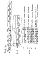
- Fig. 1 is a circuit block diagram showing a currently proposed system in which video and audio signals transmitted from a broadcast satellite station are respectively demodulated and then transmitted through a CATV transmission line;
- Fig. 2 is a waveform diagram showing a signal system which is used in the system shown in Fig. l;
- Figs. 3A to 3C are respectively signal format diagrams of digital signals used in a CATV system according to this invention;
- Fig. 4 is a circuit block diagram showing an embodiment of the CATV system according to this invention;
- Fig. 5 is a diagram showing a transmission channel used in the CATV system of the invention shown in Fig. 4;
- Fig. 6 is a circuit block diagram showing another embodiment of the CATV system according to this inventions and
- Fig. 7 is a diagram showing a transmission channel used in the CATV system of the invention shown in Fig. 6.
- Now, the present invention will hereinafter be described with reference to the drawings.
- In this invention, the video signals are transmitted as explained in connection with Fig. 1, while the audio signals are converted to PCM signals having signal formats as shown in Figs. 3A to 3C and then transmitted to a different channel.
- As shown in Fig. 3A, this PCM signal is a binary signal having a large number of frames and one frame thereof is formed of 256 words, Wl to W256. One word thereof is formed of 168 bits and the cycle or period thereof is 1/44.1 kHz (22.7 µ sec) as shown in Fig. 3B. In each word, a word synchronizing code SYNC of 8-bit, a service bit SB of 4-bit, data bits CHA to CHD of 32 bits x 4 and an error correction bit of 7 bits x 4 are multiplexed with one another in time-division manner.
- In this case, as shown in Fig. 3A, the word synchronizing code SYNC is made as a frame synchronizing codes FS in the first word W1 of the frame and is coded as a word synchronizing code WS in other 255 words W2 to W256. The bit pattern of the word synchronizing code WS is different from that of the frame synchronizing code FS.
- The service bit SB .is a signal which takes bits of one frame, namely, 4 x 256 = 1024 bits as one unit and indicates an address signal for each
terminal 3 and the content of service (permission for listening to pay channel audio broadcasting) for theterminal 3. Also, the service bit code SB can be used as a mode switching signal which indicates the kind of a digital signal to be transmitted. As a result, on the basis of such mode switching signal, in case of particular pattern, the PCM signal broadcast from the broadcast satellite is transmitted to the CATV transmission line and the particular pattern is identified on the receiving side, whereby the television receiver is switched into an operative mode. - Further, the data bits CHA to CHD are each formed of 32 bits and construct four independent channels CHA to CHD. Each of the channels CHA to CHD can adopt any one of modes A to D which are shown in Fig. 3C.
- In the mode A, left and right channel stereo audio signals L and R are sampled by a sampling frequency of 44.1 kHz and encoded to PCM signals of 16 bits each. The signal format of these PCM signals is the same signal format of DAD (digital audio disc) in a so-called CD (compact disc) system. Accordingly, the mode A provides for a stereo audio signal of extremely high quality.
- IH the mode B, two pairs of stereo signals L1, R1 and L2, R2 are respectively sampled by the frequency of 44.1 kHz and then encoded to PCM signals of 8 bits, respectively. In the mode B, the noise reduction is carried out by signal-expandingand signal-compressing the audio signals L1 to R2, too. Consequently, in accordance with the mode B, it is possible to provide a stereo broadcasting of high quality in two different channels.
- In the mode C, monaural signals M1 to M8 channels are sampled by a frequency of 22.05kHz and then respectively encoded to PCM signals of 8 bits. In this case, in accordance with the use, some of the monaural signals M1 to M8 are used for facsimile and the like. Thus, in this mode C, it is possible to realize services such as news, weather forecast, emergency broadcasting, facsimile and so on.
- Further, in the mode D, the mode B and the mode C are combined to each other so as to realize one channel so that this mode D can cope with more elaborate service.
- The modes A to D and the channels CHA to CHD can freely be combined with one another.
- 7 bits each of the error correction code ECC are used to carry out the error correction of the channels CHA to CHD and a BCH code, by way of example, can be used as the code ECC.
- The PCM signal Sp with the signal format as described above has the transmission bit rate as given by
168 bits x 44.1 kHz ≅ 7.4Mb/s Thus, the PCM signal Sp can be transmitted by using the frequency band of 6.MHz which is the frequency band of one channel in the television broadcasting. - Fig. 4 schematically illustrates an embodiment of the CATV system according to the present invention, in which a radio wave of four channels from the
broadcast satellite 1 is received and then transmitted to eachterminal 3. In Fig. 4, like parts corresponding to those in Fig. 1 are marked with the same references and will not be described in detail. - As shown in Fig. 4, in the CATV center 2, the video signals V1 to V4 and the audio signals S1 to S4 derived from the
indoor units 231 to 234 are respectively supplied tomodulators 261 to 264, in which they are modulated to the television signals T1 to T4, each of which has a different channel as, for example, shown in Fig. 5. These television signals T1 to T4 are fed to the mixingcircuit 25. - From the
indoor units 231 to 234, derived are PCM audio signals, namely, audio signals P1 to P4 which were subjected to error correction processing but not to D/A (digital-to-analog)-conversion. These signals P1 to P4 are respectively supplied to aninterface circuit 27 and then converted to the PCM signals Sp which was described in connection with Fig. 3. In this case, the signals P1 to P4 are respectively assigned to the channels CHA to CHD and every channel is set in the mode A. - Then, this PCM signal Sp is supplied to a VSB (vestigial side band)
modulator 265 thereby modulated to a VSB signal T5 having an occupied-frequency band of 6 MHz, namely, signal T5 of the same system as that of the modulated signal when the video carrier wave is modulated by the video signal in the current television broadcasting. This signal T5 is supplied to the mixingcircuit 25. From the mixingcircuit 25, a signal which results from mixing the signals T1 to T5 is sent to thecoaxial cable 6. - While, in a terminal 30, the signal from the
cable 6 is supplied to atuner 31, in which a television signal Ti (i is an integer of any one of 1 to 4) of a desired channel is frequency-converted to a video intermediate frequency signal. This video intermediate frequency signal Ti is supplied through a videointermediate frequency amplifier 32 to avideo detector 33, in which the video intermediate frequency signal is demodulated to a video signal. This video signal is supplied to acolor demodulator 34 thereby demodulated to three primary color signals R, G and B. These three primary color signals R, G and B are respectively supplied to a colorcathode ray tube 35 in which a color signal is reproduced. - Further, the signal from the
coaxial cable 6 is supplied to a front end (tuner circuit) 41, in which the signal T5 is frequency-converted to an intermediate frequency signal. This signal is supplied through anintermediate frequency amplifier 42 to ademodulator 43, in which it is demodualted to the PCM signal Sp. This PCM signal Sp is supplied to achannel selector 44 from which the digital data of the channel CHi corresponding to the channel (signal Ti) which was selected from the channels CHA to CHD in thetuner 31 is derived. This digital data is supplied to adecoder 45, in which it is subjected to error correction. - Thereafter, this digital data is supplied .to D/
A converters amplifiers speakers - While, at the
general terminal 3, the image and sound are reproduced from the signals T1 to T4. - Another embodiment of the CATV system according to this invention will be described with reference to Fig. 6. In the embodiment shown in Fig. 6, like circuit elements corresponding to those in Fig. 4 are marked with the same references and will not be described in detail. In this embodiment, the radio wave of 4 channels is received from the
broadcast satellite 1 and the video signal and the audio signal are respectively transmitted through independent channels to eachterminal 3. - In Fig. 6, in the CATV center 2, the video signals Vl to V4 from indoor units 231' to 234' are respectively supplied to VSB modulators 261' to 264', in which they are modulated to the television signals T1 to T4 of wide frequency band, each having a different channel as, for example, shown in Fig. 7. However, these television signals T1 to T4 have no audio signals S1 to S4 shown in Fig. 5. These television signals T1 to T4 are respectively, supplied to the mixing
circuit 25. - Further, derived from the indoor units 231' to 234' are the PCM audio signals, namely, digital audio signals P1 to P4 which are not yet subjected to D/A-conversion. These digital audio signals PI to P4 are respectively supplied to an interface circuit 27' thereby converted to the PCM signal Sp which was explained in connection with Fig. 3. In this case, the signals P1 to P4 are respectively assigned to the channels CHA to CHD and any one of the channels CHA to CHD is set in the mode A of 16 bits with the sampling frequency of 44.1 kHz.
- This PCM signal Sp is supplied to the
VSB modulator 265 thereby modulated to the VSB signal T5 having the occupied-frequency band of 6 MHz, namely, the signal T5 of the same band width as that of the modulated signal when the video carrièrwave is modulated by the video signal in the current television broadcast. This signal T5 is also supplied to the mixingcircuit 25 so that the mixed signal of the signals T1 to T5 is delivered from the mixing circuit-25 to thecoaxial cable 6. - Further, in the
terminal 3, the signal from thecoaxial cable 6 is supplied to thetuner 31, in which the television signal Ti (i is the integer of any one of 1 to 4) of the desired channel is frequency-converted to the video intermediate frequency signal. This signal is supplied through the videointermediate frequency amplifier 32 to thevideo detector 33 in which it is demodulated to the video signal. This video signal is supplied to thecolor demodulator 34 thereby demodulated to the three primary color signals R, G and B. These three primary color signals R, G and B are fed to the colorcathode ray tube 35 on which then a color picture image is reproduced. - The signal from the
coaxial cable 6 is supplied to the front end (tuner circuit)441, in which the signal TS is frequency-converted to the intermediate frequency signal. This signal is supplied through theintermediate frequency amplifier 42 to thedemodulator 43 thereby demodulated to the PCM signal Sp. This PCM signal Sp is supplied to thechannel selector 44 which produces the digital audio signal of the channel CHi corresponding to the channel (signal Ti) selected from the channels CHAto CHD in thetuner 31, This digital audio signal is supplied to thedecoder 45 and subjected to error correction. - Thereafter, this digital audio signal is supplied to the D/
A converters amplifiers speakers - As described above, according to this invention, the television broadcast sent through the
broadcast sarellite 1 can be viewed by the CATV system. In this case, particularly in accordance with this invention, since the audio signal which is transmitted from thesatellite broadcast 1 in the form of the PCM signal is converted in signal format and then transmitted in the form of the PCM signal to each terminal 3, the tone quality thereof is never detericrated and it is possible to reproduce sound of remarkably high quality. - In the CATV system shown in Fig. 1, when the television signals are assigned to the successive channels as shown in Fig. 2, the occupied-frequency bands of the audio signals S1 to S4 must be narrowed in order to alleviate the interference between the adjacent channels in the
terminal 3, thus the stereo broadcasting being made impossible. Therefore, in practice, the television signals T1 to T4 are assigned to every other channel so that on the whole, the wide frequency band must be provided. However, according to this invention, since the audio signals S1 to S4 are not contained in the television signals T1 to T4, the television signals T1 to T5 can be assigned to the consecutive channels as shown in Fig. 7 so that in spite of the television signals T5, it is possible to narrow the necessary frequency band to, for example, 30 MHz on the whole. - If it is permitted to assign the television signals T1 to T5 to every other channel, the video signals V1 to V4 can occupy all the frequency bands of 6 MHz in each channel so that it is possible to transmit signals of higher quality as the video signals V1 to V4.
- As is clear from the description as mentioned above, according to this invention, the television broadcast transmitted through the
broadcast satellite 1 can be viewed and heard by the CATV system. Particularly in accordance with this invention, since the audio signal sent from thebroadcast satellite 1 in the form of PCM signal is converted in signal format and then transmitted to the terminal 30 in the form of PCM signal, it is possible to--prevent the tone quality thereof from being deteriorated and hence sound of extremely-high quality can be played back. - Further, since the television signals T1 to T4 have the ordinary format of the video and audio signals, it is possible to enjoy at the
general terminal 3 the broadcast satellite television program in which the audio signal is not the PCM signal. - Furthermore, without modifying the existing CATV system particularly, it is possible to supply to each terminal 3 the picture image and sound of high quality by the broadcast satellite.
- Since the signal format as shown in Fig. 3 is used to send other audio signal than that used in the broadcast satellite and information signal such as facsimile simultaneously, it is possible to provide a wide variety of services more elaborately.
- Further, since the CATV system of the invention is compatible with the prior art CATV system, even the user at the
general terminal 3 can enjoy the television program of the broadcast satellite similarly. Since the user at the terminal 30 receives the audio signal which is transmitted with the tone quality of the PCM signal, the user can enjoy a so-called Hi-Fi sound of extremely high quality. Further, the CATV system of this invention can cope with a case in which the sound of the broadcast satellite is made high in quality and is made suitable for the multichannel so that the CATV system of this invention can cope with the future development. - Furthermore, in the embodiment shown in Fig. 6, the audio signal is transmitted through the different channel from that of the video signal and the audio frequency band within the television channel in the prior art can be assigned to the frequency band of the video signal so that the frequency band of the video signal can be made wider by that much, thus the picture image of high quality being transmitted. In addition, the CATV system of this invention can cope with-the multichannel audio system of the broadcast satellite and so, this CATV system becomes the system which can cope with the future development.
- The above description is given on the preferred embodiments of the invention, but it will be apparent that many modifications and variations could be effected by one skilled in the art without departing.from the spirits or scope of the novel concepts of the invention, so that the scope of the invention should be determined by the appended claims only.
Claims (11)
Applications Claiming Priority (4)
| Application Number | Priority Date | Filing Date | Title |
|---|---|---|---|
| JP208741/83 | 1983-11-07 | ||
| JP20874183A JPS60100889A (en) | 1983-11-07 | 1983-11-07 | Catv system |
| JP20948883A JPS60102080A (en) | 1983-11-08 | 1983-11-08 | Catv system |
| JP209488/83 | 1983-11-08 |
Publications (3)
| Publication Number | Publication Date |
|---|---|
| EP0144770A2 true EP0144770A2 (en) | 1985-06-19 |
| EP0144770A3 EP0144770A3 (en) | 1986-02-19 |
| EP0144770B1 EP0144770B1 (en) | 1989-08-02 |
Family
ID=26517022
Family Applications (1)
| Application Number | Title | Priority Date | Filing Date |
|---|---|---|---|
| EP84113367A Expired EP0144770B1 (en) | 1983-11-07 | 1984-11-06 | Catv signal transmitting system and related receiving system |
Country Status (5)
| Country | Link |
|---|---|
| US (1) | US4805014A (en) |
| EP (1) | EP0144770B1 (en) |
| AU (1) | AU576787B2 (en) |
| CA (1) | CA1223335A (en) |
| DE (1) | DE3479280D1 (en) |
Cited By (17)
| Publication number | Priority date | Publication date | Assignee | Title |
|---|---|---|---|---|
| US4621282A (en) * | 1984-04-26 | 1986-11-04 | British Telecommunications Plc | Transmitting stereo audio programs in cable TV systems |
| US4684981A (en) * | 1983-11-09 | 1987-08-04 | Sony Corporation | Digital terminal address transmitting for CATV |
| US4691351A (en) * | 1984-11-29 | 1987-09-01 | Sony Corporation | Television signal receiving apparatus |
| US4723285A (en) * | 1984-05-29 | 1988-02-02 | Compagnie Industrielles Des Telecommunications Cit-Alcatel | Methods of broadcasting and receiving high quality sound programs and a receiver device |
| EP0271805A2 (en) * | 1986-12-17 | 1988-06-22 | Deutsche Thomson-Brandt GmbH | Transmission system |
| EP0277014A2 (en) * | 1987-01-30 | 1988-08-03 | Sony Corporation | Service and entertainment communication system |
| EP0277015A2 (en) * | 1987-01-30 | 1988-08-03 | Sony Corporation | Electric message delivery systems |
| EP0284799A2 (en) * | 1987-03-05 | 1988-10-05 | General Instrument Corporation | Apparatus and method for providing digital audio on the sound carrier of a standard television signal |
| US4805014A (en) * | 1983-11-07 | 1989-02-14 | Sony Corporation | Signal transmission system for a CATV system |
| US4835604A (en) * | 1987-02-23 | 1989-05-30 | Sony Corporation | Aircraft service system with a central control system for attendant call lights and passenger reading lights |
| US4896209A (en) * | 1987-02-10 | 1990-01-23 | Sony Corporation | Passenger vehicle polling system having a central unit for polling passenger seat terminal units |
| US4897714A (en) * | 1987-02-25 | 1990-01-30 | Sony Corporation | Passenger vehicle service system |
| US4958381A (en) * | 1987-02-17 | 1990-09-18 | Sony Corporation | Two way communication system |
| US4959862A (en) * | 1988-04-28 | 1990-09-25 | Catel Telecommunications, Inc. | Active multichannel video processing hub for optimum transition from fiber to coax |
| EP0497449A2 (en) * | 1991-01-31 | 1992-08-05 | Pioneer Electronic Corporation | Information transmission system |
| WO1997001243A1 (en) * | 1995-06-20 | 1997-01-09 | Tovarischestvo S Ogranichennoi Otvetstvennostju 'universal Kommunications' | Method of broadcasting television programmes with simultaneous interpretation |
| US5970386A (en) * | 1997-01-27 | 1999-10-19 | Hughes Electronics Corporation | Transmodulated broadcast delivery system for use in multiple dwelling units |
Families Citing this family (76)
| Publication number | Priority date | Publication date | Assignee | Title |
|---|---|---|---|---|
| US4965825A (en) | 1981-11-03 | 1990-10-23 | The Personalized Mass Media Corporation | Signal processing apparatus and methods |
| US7831204B1 (en) | 1981-11-03 | 2010-11-09 | Personalized Media Communications, Llc | Signal processing apparatus and methods |
| USRE47642E1 (en) | 1981-11-03 | 2019-10-08 | Personalized Media Communications LLC | Signal processing apparatus and methods |
| NO172420C (en) * | 1989-04-24 | 1993-07-14 | Complan Network As | DEVICE BY TV COMMUNICATION SYSTEM |
| US5099319A (en) * | 1989-10-23 | 1992-03-24 | Esch Arthur G | Video information delivery method and apparatus |
| US5125100A (en) * | 1990-07-02 | 1992-06-23 | Katznelson Ron D | Optimal signal synthesis for distortion cancelling multicarrier systems |
| US5253275A (en) * | 1991-01-07 | 1993-10-12 | H. Lee Browne | Audio and video transmission and receiving system |
| US7894541B2 (en) * | 1992-03-26 | 2011-02-22 | Panasonic Corporation | Communication system |
| US5819000A (en) * | 1992-03-26 | 1998-10-06 | Matsushita Electric Industrial Co., Ltd. | Magnetic recording and playback apparatus |
| US7509270B1 (en) | 1992-12-09 | 2009-03-24 | Discovery Communications, Inc. | Electronic Book having electronic commerce features |
| US5659350A (en) | 1992-12-09 | 1997-08-19 | Discovery Communications, Inc. | Operations center for a television program packaging and delivery system |
| US9286294B2 (en) | 1992-12-09 | 2016-03-15 | Comcast Ip Holdings I, Llc | Video and digital multimedia aggregator content suggestion engine |
| US7849393B1 (en) | 1992-12-09 | 2010-12-07 | Discovery Communications, Inc. | Electronic book connection to world watch live |
| US7336788B1 (en) | 1992-12-09 | 2008-02-26 | Discovery Communicatoins Inc. | Electronic book secure communication with home subsystem |
| US5798785A (en) | 1992-12-09 | 1998-08-25 | Discovery Communications, Inc. | Terminal for suggesting programs offered on a television program delivery system |
| US7401286B1 (en) * | 1993-12-02 | 2008-07-15 | Discovery Communications, Inc. | Electronic book electronic links |
| US8073695B1 (en) | 1992-12-09 | 2011-12-06 | Adrea, LLC | Electronic book with voice emulation features |
| US5600364A (en) | 1992-12-09 | 1997-02-04 | Discovery Communications, Inc. | Network controller for cable television delivery systems |
| US7298851B1 (en) * | 1992-12-09 | 2007-11-20 | Discovery Communications, Inc. | Electronic book security and copyright protection system |
| US5600573A (en) | 1992-12-09 | 1997-02-04 | Discovery Communications, Inc. | Operations center with video storage for a television program packaging and delivery system |
| US6201536B1 (en) * | 1992-12-09 | 2001-03-13 | Discovery Communications, Inc. | Network manager for cable television system headends |
| ATE219615T1 (en) * | 1992-12-09 | 2002-07-15 | Discovery Communicat Inc | NETWORK CONTROL FOR CABLE TELEVISION DISTRIBUTION SYSTEMS |
| US7269841B1 (en) | 1992-12-09 | 2007-09-11 | Sedna Patent Services, Llc | Digital cable headend for cable television delivery system |
| US7168084B1 (en) | 1992-12-09 | 2007-01-23 | Sedna Patent Services, Llc | Method and apparatus for targeting virtual objects |
| US6181335B1 (en) | 1992-12-09 | 2001-01-30 | Discovery Communications, Inc. | Card for a set top terminal |
| US6463585B1 (en) | 1992-12-09 | 2002-10-08 | Discovery Communications, Inc. | Targeted advertisement using television delivery systems |
| US7073187B1 (en) | 1992-12-09 | 2006-07-04 | Sedna Patent Services, Llc | Menu-driven television program access system and method |
| US7835989B1 (en) | 1992-12-09 | 2010-11-16 | Discovery Communications, Inc. | Electronic book alternative delivery systems |
| US5841971A (en) * | 1992-12-17 | 1998-11-24 | Voxson International Pty. Limited | Information transmission system for transmitting video signals over cellular telephone networks |
| US7861166B1 (en) | 1993-12-02 | 2010-12-28 | Discovery Patent Holding, Llc | Resizing document pages to fit available hardware screens |
| US9053640B1 (en) | 1993-12-02 | 2015-06-09 | Adrea, LLC | Interactive electronic book |
| US8095949B1 (en) | 1993-12-02 | 2012-01-10 | Adrea, LLC | Electronic book with restricted access features |
| US7865567B1 (en) | 1993-12-02 | 2011-01-04 | Discovery Patent Holdings, Llc | Virtual on-demand electronic book |
| JPH07273695A (en) * | 1994-01-24 | 1995-10-20 | Yair Maryanka | Transmission of voice,music,image and data through dc conductor |
| US5553140A (en) * | 1994-05-26 | 1996-09-03 | Sony Corporation Of Japan | Digital and analog interface for set back box |
| US5488413A (en) * | 1994-06-14 | 1996-01-30 | Xel Communications, Inc. | CATV telephony system using subsplit band for both directions of transmission |
| TW250616B (en) * | 1994-11-07 | 1995-07-01 | Discovery Communicat Inc | Electronic book selection and delivery system |
| JP3645308B2 (en) * | 1995-05-01 | 2005-05-11 | 富士通株式会社 | Service distribution method with mixed analog and digital broadcasting services |
| SG55251A1 (en) * | 1995-12-20 | 2000-08-22 | Koninkl Philips Electronics Nv | Television signal cable distribution installation |
| US5959660A (en) * | 1996-08-26 | 1999-09-28 | Hybrid Networks, Inc. | Subchannelization scheme for use in a broadband communications system |
| US5960353A (en) * | 1996-12-24 | 1999-09-28 | Lucent Technologies, Inc. | Microcell load measurement using feedback control |
| KR100251590B1 (en) * | 1996-12-30 | 2000-04-15 | 김영환 | Optical catv system which has improved the transfering efficiency of communication channel |
| US6104908A (en) * | 1997-02-28 | 2000-08-15 | Hughes Electronics Corporation | System for and method of combining signals of combining signals of diverse modulation formats for distribution in multiple dwelling units |
| WO1999053692A1 (en) * | 1998-04-13 | 1999-10-21 | Trilithic, Inc. | Communication apparatus with modulators and oscillators |
| US9009773B1 (en) | 1998-06-30 | 2015-04-14 | Cox Communications, Inc. | Method and apparatus for providing broadcast data services |
| US7051360B1 (en) * | 1998-11-30 | 2006-05-23 | United Video Properties, Inc. | Interactive television program guide with selectable languages |
| US6792615B1 (en) * | 1999-05-19 | 2004-09-14 | New Horizons Telecasting, Inc. | Encapsulated, streaming media automation and distribution system |
| BR0012516A (en) * | 1999-07-16 | 2002-04-02 | United Video Properties Inc | Interactive television program guide with selectable languages |
| US7165365B1 (en) * | 2000-04-03 | 2007-01-23 | The Directv Group, Inc. | Satellite ready building and method for forming the same |
| US7142809B1 (en) * | 2001-02-27 | 2006-11-28 | The Directv Group, Inc. | Device and method to locally fill gaps in spotbeam satellite systems with frequency re-use |
| US20020154055A1 (en) * | 2001-04-18 | 2002-10-24 | Robert Davis | LAN based satellite antenna/satellite multiswitch |
| US7908628B2 (en) * | 2001-08-03 | 2011-03-15 | Comcast Ip Holdings I, Llc | Video and digital multimedia aggregator content coding and formatting |
| US7793326B2 (en) | 2001-08-03 | 2010-09-07 | Comcast Ip Holdings I, Llc | Video and digital multimedia aggregator |
| US7954127B2 (en) * | 2002-09-25 | 2011-05-31 | The Directv Group, Inc. | Direct broadcast signal distribution methods |
| US7950038B2 (en) * | 2005-04-01 | 2011-05-24 | The Directv Group, Inc. | Transponder tuning and mapping |
| US7945932B2 (en) * | 2005-04-01 | 2011-05-17 | The Directv Group, Inc. | Narrow bandwidth signal delivery system |
| US8024759B2 (en) * | 2005-04-01 | 2011-09-20 | The Directv Group, Inc. | Backwards-compatible frequency translation module for satellite video delivery |
| US7900230B2 (en) * | 2005-04-01 | 2011-03-01 | The Directv Group, Inc. | Intelligent two-way switching network |
| US7958531B2 (en) | 2005-04-01 | 2011-06-07 | The Directv Group, Inc. | Automatic level control for incoming signals of different signal strengths |
| US8621525B2 (en) * | 2005-04-01 | 2013-12-31 | The Directv Group, Inc. | Signal injection via power supply |
| US7987486B2 (en) * | 2005-04-01 | 2011-07-26 | The Directv Group, Inc. | System architecture for control and signal distribution on coaxial cable |
| US8549565B2 (en) * | 2005-04-01 | 2013-10-01 | The Directv Group, Inc. | Power balancing signal combiner |
| US8789115B2 (en) * | 2005-09-02 | 2014-07-22 | The Directv Group, Inc. | Frequency translation module discovery and configuration |
| US7937732B2 (en) * | 2005-09-02 | 2011-05-03 | The Directv Group, Inc. | Network fraud prevention via registration and verification |
| US20080016535A1 (en) * | 2005-09-02 | 2008-01-17 | The Directv Group, Inc. | Frequency shift key control in video delivery systems |
| US7991348B2 (en) | 2005-10-12 | 2011-08-02 | The Directv Group, Inc. | Triple band combining approach to satellite signal distribution |
| US8019275B2 (en) * | 2005-10-12 | 2011-09-13 | The Directv Group, Inc. | Band upconverter approach to KA/KU signal distribution |
| US20070089142A1 (en) * | 2005-10-14 | 2007-04-19 | John Norin | Band converter approach to Ka/Ku signal distribution |
| BRPI0712582A2 (en) * | 2006-06-09 | 2012-10-16 | Directv Group Inc | system for receiving satellite video signals for display on a monitor and apparatus for displaying video information |
| US20080060021A1 (en) * | 2006-06-16 | 2008-03-06 | Hanno Basse | Digital storage media command and control data indexing |
| US8719875B2 (en) | 2006-11-06 | 2014-05-06 | The Directv Group, Inc. | Satellite television IP bitstream generator receiving unit |
| US8712318B2 (en) | 2007-05-29 | 2014-04-29 | The Directv Group, Inc. | Integrated multi-sat LNB and frequency translation module |
| US8238813B1 (en) | 2007-08-20 | 2012-08-07 | The Directv Group, Inc. | Computationally efficient design for broadcast satellite single wire and/or direct demod interface |
| US9942618B2 (en) * | 2007-10-31 | 2018-04-10 | The Directv Group, Inc. | SMATV headend using IP transport stream input and method for operating the same |
| US8229383B2 (en) | 2009-01-06 | 2012-07-24 | The Directv Group, Inc. | Frequency drift estimation for low cost outdoor unit frequency conversions and system diagnostics |
| RU2496219C2 (en) * | 2011-12-19 | 2013-10-20 | Закрытое акционерное общество "Электропривод и силовая Электроника" | Control method of frequency-assisted electric drive |
Citations (1)
| Publication number | Priority date | Publication date | Assignee | Title |
|---|---|---|---|---|
| DE3223408A1 (en) * | 1981-06-25 | 1983-01-13 | N.V. Philips' Gloeilampenfabrieken, 5621 Eindhoven | COMMUNITY ANTENNA ARRANGEMENT FOR RECEIVING AND DISTRIBUTING TELEVISION AND DIGITAL AUDIO SIGNALS |
Family Cites Families (12)
| Publication number | Priority date | Publication date | Assignee | Title |
|---|---|---|---|---|
| US3757225A (en) * | 1972-03-16 | 1973-09-04 | Telebeam Corp | Communication system |
| US3988528A (en) * | 1972-09-04 | 1976-10-26 | Nippon Hoso Kyokai | Signal transmission system for transmitting a plurality of information signals through a plurality of transmission channels |
| US4215370A (en) * | 1978-02-22 | 1980-07-29 | Digital Communications, Inc. | Satellite video multiplexing communications system |
| JPS5571382A (en) * | 1978-11-24 | 1980-05-29 | Hitachi Ltd | Buffer memory dispersive arrangement-type picture sound transmission system |
| JPS55141874A (en) * | 1979-04-23 | 1980-11-06 | Pioneer Electronic Corp | Television audio multiplex broadcast system in catv system |
| DE3135005A1 (en) * | 1981-09-04 | 1983-03-24 | Standard Elektrik Lorenz Ag, 7000 Stuttgart | PRIVATE MESSAGE TRANSMISSION SYSTEM |
| NL8105609A (en) * | 1981-12-14 | 1983-07-01 | Philips Nv | COMMON AERIAL / DEVICE. |
| JPS5915387A (en) * | 1982-07-15 | 1984-01-26 | Sony Corp | Digital signal transmitting system using catv line |
| JPS5915388A (en) * | 1982-07-15 | 1984-01-26 | Sony Corp | Digital signal transmission system using catv line |
| US4633462A (en) * | 1983-07-18 | 1986-12-30 | The Board Of Trustees Of The University Of Illinois | Multiple access communication on a CATV reverse channel |
| AU576787B2 (en) * | 1983-11-07 | 1988-09-08 | Sony Corporation | Satellite to cable television interface |
| JPH0654973B2 (en) * | 1983-11-09 | 1994-07-20 | ソニー株式会社 | Digital signal transmission device using CATV line |
-
1984
- 1984-10-30 AU AU34835/84A patent/AU576787B2/en not_active Ceased
- 1984-11-01 CA CA000466851A patent/CA1223335A/en not_active Expired
- 1984-11-06 DE DE8484113367T patent/DE3479280D1/en not_active Expired
- 1984-11-06 EP EP84113367A patent/EP0144770B1/en not_active Expired
-
1987
- 1987-09-14 US US07/096,773 patent/US4805014A/en not_active Expired - Fee Related
Patent Citations (1)
| Publication number | Priority date | Publication date | Assignee | Title |
|---|---|---|---|---|
| DE3223408A1 (en) * | 1981-06-25 | 1983-01-13 | N.V. Philips' Gloeilampenfabrieken, 5621 Eindhoven | COMMUNITY ANTENNA ARRANGEMENT FOR RECEIVING AND DISTRIBUTING TELEVISION AND DIGITAL AUDIO SIGNALS |
Non-Patent Citations (2)
| Title |
|---|
| FUNKSCHAU 1974, no. 18, Munchen ANTON KOHLER, "Satelliten-Fernsehempfang in Gemeinschaftsantennen - Anlagen" pages 689-692 * |
| NACHRICTENTECHNISCHE ZEITSCHRIFT ntz, vol. 36, no. 6, 1983, Berlin PETER H. GRAF et al. "Digitale Tonubertragung Uber Satelliten" pages 364-370 * |
Cited By (25)
| Publication number | Priority date | Publication date | Assignee | Title |
|---|---|---|---|---|
| US4805014A (en) * | 1983-11-07 | 1989-02-14 | Sony Corporation | Signal transmission system for a CATV system |
| US4684981A (en) * | 1983-11-09 | 1987-08-04 | Sony Corporation | Digital terminal address transmitting for CATV |
| US4621282A (en) * | 1984-04-26 | 1986-11-04 | British Telecommunications Plc | Transmitting stereo audio programs in cable TV systems |
| US4723285A (en) * | 1984-05-29 | 1988-02-02 | Compagnie Industrielles Des Telecommunications Cit-Alcatel | Methods of broadcasting and receiving high quality sound programs and a receiver device |
| US4691351A (en) * | 1984-11-29 | 1987-09-01 | Sony Corporation | Television signal receiving apparatus |
| EP0271805A2 (en) * | 1986-12-17 | 1988-06-22 | Deutsche Thomson-Brandt GmbH | Transmission system |
| EP0271805A3 (en) * | 1986-12-17 | 1989-09-06 | Deutsche Thomson-Brandt Gmbh | Transmission system |
| EP0277014A3 (en) * | 1987-01-30 | 1991-06-26 | Sony Corporation | Service and entertainment communication system |
| EP0277014A2 (en) * | 1987-01-30 | 1988-08-03 | Sony Corporation | Service and entertainment communication system |
| EP0277015A2 (en) * | 1987-01-30 | 1988-08-03 | Sony Corporation | Electric message delivery systems |
| US4866515A (en) * | 1987-01-30 | 1989-09-12 | Sony Corporation | Passenger service and entertainment system for supplying frequency-multiplexed video, audio, and television game software signals to passenger seat terminals |
| EP0277015A3 (en) * | 1987-01-30 | 1991-06-26 | Sony Corporation | Electric message delivery systems |
| US4887152A (en) * | 1987-01-30 | 1989-12-12 | Sony Corporation | Message delivery system operable in an override mode upon reception of a command signal |
| US4896209A (en) * | 1987-02-10 | 1990-01-23 | Sony Corporation | Passenger vehicle polling system having a central unit for polling passenger seat terminal units |
| US4958381A (en) * | 1987-02-17 | 1990-09-18 | Sony Corporation | Two way communication system |
| US4835604A (en) * | 1987-02-23 | 1989-05-30 | Sony Corporation | Aircraft service system with a central control system for attendant call lights and passenger reading lights |
| US4897714A (en) * | 1987-02-25 | 1990-01-30 | Sony Corporation | Passenger vehicle service system |
| EP0284799A3 (en) * | 1987-03-05 | 1989-09-20 | General Instrument Corporation | Apparatus and method for providing digital audio on the sound carrier of a standard television signal |
| EP0284799A2 (en) * | 1987-03-05 | 1988-10-05 | General Instrument Corporation | Apparatus and method for providing digital audio on the sound carrier of a standard television signal |
| US4959862A (en) * | 1988-04-28 | 1990-09-25 | Catel Telecommunications, Inc. | Active multichannel video processing hub for optimum transition from fiber to coax |
| EP0497449A2 (en) * | 1991-01-31 | 1992-08-05 | Pioneer Electronic Corporation | Information transmission system |
| EP0497449A3 (en) * | 1991-01-31 | 1994-03-09 | Pioneer Electronic Corp | |
| WO1997001243A1 (en) * | 1995-06-20 | 1997-01-09 | Tovarischestvo S Ogranichennoi Otvetstvennostju 'universal Kommunications' | Method of broadcasting television programmes with simultaneous interpretation |
| US5970386A (en) * | 1997-01-27 | 1999-10-19 | Hughes Electronics Corporation | Transmodulated broadcast delivery system for use in multiple dwelling units |
| US6493873B1 (en) | 1997-01-27 | 2002-12-10 | Hughes Electronics Corporation | Transmodulator with dynamically selectable channels |
Also Published As
| Publication number | Publication date |
|---|---|
| DE3479280D1 (en) | 1989-09-07 |
| US4805014A (en) | 1989-02-14 |
| CA1223335A (en) | 1987-06-23 |
| EP0144770A3 (en) | 1986-02-19 |
| AU3483584A (en) | 1985-05-16 |
| AU576787B2 (en) | 1988-09-08 |
| EP0144770B1 (en) | 1989-08-02 |
Similar Documents
| Publication | Publication Date | Title |
|---|---|---|
| US4805014A (en) | Signal transmission system for a CATV system | |
| EP0372499B1 (en) | Apparatus and method for providing digital audio in the FM broadcast band | |
| US4656629A (en) | Digital signal transmitting and/or receiving system | |
| US5521943A (en) | COFDM combined encoder modulation for digital broadcasting sound and video with PSK, PSK/AM, and QAM techniques | |
| US6901242B2 (en) | System and method for mitigating intermittent interruptions in an audio radio broadcast system | |
| US5325127A (en) | Process for transmitting digital data, in particular sound data, in a TV channel | |
| US4646150A (en) | Apparatus and method for stereo television sound | |
| US3754099A (en) | Four channel stereophonic broadcasting system | |
| CA1244154A (en) | Digital signal transmitting system | |
| JP3398961B2 (en) | Scramble system | |
| JPS60102080A (en) | Catv system | |
| JP2832961B2 (en) | CATV transmission system | |
| JPH0467816B2 (en) | ||
| JPS60100889A (en) | Catv system | |
| JPS59151585A (en) | Satellite broadcast equipment | |
| Rumsey | Hearing both sides-stereo sound for TV in the UK | |
| JPH11331004A (en) | Digital broadcast recording system and digital radio broadcast recording system | |
| JPH0531332B2 (en) | ||
| JPS5991748A (en) | Pcm signal transmission and receiving system | |
| JPS59211380A (en) | Community receiving system of satelite broadcasting | |
| JPH0775072A (en) | Transmission system for digital audio signal | |
| EP1025693A1 (en) | Method for transferring information | |
| Osborne | Sound and data on DBS | |
| JPS61117932A (en) | Fm stereo broadcast system in catv | |
| Bower | Department Report |
Legal Events
| Date | Code | Title | Description |
|---|---|---|---|
| PUAI | Public reference made under article 153(3) epc to a published international application that has entered the european phase |
Free format text: ORIGINAL CODE: 0009012 |
|
| AK | Designated contracting states |
Designated state(s): DE FR GB NL |
|
| PUAL | Search report despatched |
Free format text: ORIGINAL CODE: 0009013 |
|
| AK | Designated contracting states |
Designated state(s): DE FR GB NL |
|
| 17P | Request for examination filed |
Effective date: 19860108 |
|
| 17Q | First examination report despatched |
Effective date: 19880204 |
|
| GRAA | (expected) grant |
Free format text: ORIGINAL CODE: 0009210 |
|
| AK | Designated contracting states |
Kind code of ref document: B1 Designated state(s): DE FR GB NL |
|
| REF | Corresponds to: |
Ref document number: 3479280 Country of ref document: DE Date of ref document: 19890907 |
|
| ET | Fr: translation filed | ||
| PLBE | No opposition filed within time limit |
Free format text: ORIGINAL CODE: 0009261 |
|
| STAA | Information on the status of an ep patent application or granted ep patent |
Free format text: STATUS: NO OPPOSITION FILED WITHIN TIME LIMIT |
|
| 26N | No opposition filed | ||
| PGFP | Annual fee paid to national office [announced via postgrant information from national office to epo] |
Ref country code: GB Payment date: 19951030 Year of fee payment: 12 |
|
| PGFP | Annual fee paid to national office [announced via postgrant information from national office to epo] |
Ref country code: FR Payment date: 19951109 Year of fee payment: 12 |
|
| PGFP | Annual fee paid to national office [announced via postgrant information from national office to epo] |
Ref country code: DE Payment date: 19951113 Year of fee payment: 12 |
|
| PGFP | Annual fee paid to national office [announced via postgrant information from national office to epo] |
Ref country code: NL Payment date: 19951129 Year of fee payment: 12 |
|
| PG25 | Lapsed in a contracting state [announced via postgrant information from national office to epo] |
Ref country code: GB Effective date: 19961106 |
|
| PG25 | Lapsed in a contracting state [announced via postgrant information from national office to epo] |
Ref country code: NL Effective date: 19970601 |
|
| GBPC | Gb: european patent ceased through non-payment of renewal fee |
Effective date: 19961106 |
|
| PG25 | Lapsed in a contracting state [announced via postgrant information from national office to epo] |
Ref country code: FR Effective date: 19970731 |
|
| NLV4 | Nl: lapsed or anulled due to non-payment of the annual fee |
Effective date: 19970601 |
|
| PG25 | Lapsed in a contracting state [announced via postgrant information from national office to epo] |
Ref country code: DE Effective date: 19970801 |
|
| REG | Reference to a national code |
Ref country code: FR Ref legal event code: ST |