EP0145918A2 - Method and apparatus for batch carbonating - Google Patents
Method and apparatus for batch carbonating Download PDFInfo
- Publication number
- EP0145918A2 EP0145918A2 EP84113247A EP84113247A EP0145918A2 EP 0145918 A2 EP0145918 A2 EP 0145918A2 EP 84113247 A EP84113247 A EP 84113247A EP 84113247 A EP84113247 A EP 84113247A EP 0145918 A2 EP0145918 A2 EP 0145918A2
- Authority
- EP
- European Patent Office
- Prior art keywords
- orifice
- valve
- carbonator
- flow
- bore
- Prior art date
- Legal status (The legal status is an assumption and is not a legal conclusion. Google has not performed a legal analysis and makes no representation as to the accuracy of the status listed.)
- Granted
Links
- 238000000034 method Methods 0.000 title claims description 8
- CURLTUGMZLYLDI-UHFFFAOYSA-N Carbon dioxide Chemical compound O=C=O CURLTUGMZLYLDI-UHFFFAOYSA-N 0.000 claims abstract description 30
- XLYOFNOQVPJJNP-UHFFFAOYSA-N water Substances O XLYOFNOQVPJJNP-UHFFFAOYSA-N 0.000 claims abstract description 30
- 229910002092 carbon dioxide Inorganic materials 0.000 claims abstract description 15
- 239000001569 carbon dioxide Substances 0.000 claims abstract description 15
- 238000007789 sealing Methods 0.000 claims description 6
- 238000004891 communication Methods 0.000 claims description 3
- 230000000740 bleeding effect Effects 0.000 claims description 2
- BVKZGUZCCUSVTD-UHFFFAOYSA-L Carbonate Chemical compound [O-]C([O-])=O BVKZGUZCCUSVTD-UHFFFAOYSA-L 0.000 description 2
- 238000010521 absorption reaction Methods 0.000 description 2
- 230000008878 coupling Effects 0.000 description 2
- 238000010168 coupling process Methods 0.000 description 2
- 238000005859 coupling reaction Methods 0.000 description 2
- 230000000694 effects Effects 0.000 description 2
- 239000007788 liquid Substances 0.000 description 2
- 239000004033 plastic Substances 0.000 description 2
- 235000013361 beverage Nutrition 0.000 description 1
- 230000005587 bubbling Effects 0.000 description 1
- 230000003111 delayed effect Effects 0.000 description 1
- 239000003085 diluting agent Substances 0.000 description 1
- 239000013505 freshwater Substances 0.000 description 1
- 230000004941 influx Effects 0.000 description 1
- 230000002035 prolonged effect Effects 0.000 description 1
- 230000001105 regulatory effect Effects 0.000 description 1
- 238000013022 venting Methods 0.000 description 1
Images

Classifications
-
- B—PERFORMING OPERATIONS; TRANSPORTING
- B01—PHYSICAL OR CHEMICAL PROCESSES OR APPARATUS IN GENERAL
- B01F—MIXING, e.g. DISSOLVING, EMULSIFYING OR DISPERSING
- B01F23/00—Mixing according to the phases to be mixed, e.g. dispersing or emulsifying
- B01F23/20—Mixing gases with liquids
- B01F23/23—Mixing gases with liquids by introducing gases into liquid media, e.g. for producing aerated liquids
- B01F23/237—Mixing gases with liquids by introducing gases into liquid media, e.g. for producing aerated liquids characterised by the physical or chemical properties of gases or vapours introduced in the liquid media
- B01F23/2376—Mixing gases with liquids by introducing gases into liquid media, e.g. for producing aerated liquids characterised by the physical or chemical properties of gases or vapours introduced in the liquid media characterised by the gas being introduced
- B01F23/23762—Carbon dioxide
- B01F23/237621—Carbon dioxide in beverages
-
- A—HUMAN NECESSITIES
- A23—FOODS OR FOODSTUFFS; TREATMENT THEREOF, NOT COVERED BY OTHER CLASSES
- A23L—FOODS, FOODSTUFFS, OR NON-ALCOHOLIC BEVERAGES, NOT COVERED BY SUBCLASSES A21D OR A23B-A23J; THEIR PREPARATION OR TREATMENT, e.g. COOKING, MODIFICATION OF NUTRITIVE QUALITIES, PHYSICAL TREATMENT; PRESERVATION OF FOODS OR FOODSTUFFS, IN GENERAL
- A23L2/00—Non-alcoholic beverages; Dry compositions or concentrates therefor; Their preparation
- A23L2/52—Adding ingredients
- A23L2/54—Mixing with gases
-
- B—PERFORMING OPERATIONS; TRANSPORTING
- B01—PHYSICAL OR CHEMICAL PROCESSES OR APPARATUS IN GENERAL
- B01F—MIXING, e.g. DISSOLVING, EMULSIFYING OR DISPERSING
- B01F23/00—Mixing according to the phases to be mixed, e.g. dispersing or emulsifying
- B01F23/20—Mixing gases with liquids
- B01F23/23—Mixing gases with liquids by introducing gases into liquid media, e.g. for producing aerated liquids
- B01F23/236—Mixing gases with liquids by introducing gases into liquid media, e.g. for producing aerated liquids specially adapted for aerating or carbonating beverages
- B01F23/2362—Mixing gases with liquids by introducing gases into liquid media, e.g. for producing aerated liquids specially adapted for aerating or carbonating beverages for aerating or carbonating within receptacles or tanks, e.g. distribution machines
-
- B—PERFORMING OPERATIONS; TRANSPORTING
- B01—PHYSICAL OR CHEMICAL PROCESSES OR APPARATUS IN GENERAL
- B01F—MIXING, e.g. DISSOLVING, EMULSIFYING OR DISPERSING
- B01F35/00—Accessories for mixers; Auxiliary operations or auxiliary devices; Parts or details of general application
- B01F35/71—Feed mechanisms
- B01F35/712—Feed mechanisms for feeding fluids
-
- B—PERFORMING OPERATIONS; TRANSPORTING
- B01—PHYSICAL OR CHEMICAL PROCESSES OR APPARATUS IN GENERAL
- B01F—MIXING, e.g. DISSOLVING, EMULSIFYING OR DISPERSING
- B01F35/00—Accessories for mixers; Auxiliary operations or auxiliary devices; Parts or details of general application
- B01F35/71—Feed mechanisms
- B01F35/717—Feed mechanisms characterised by the means for feeding the components to the mixer
- B01F35/71805—Feed mechanisms characterised by the means for feeding the components to the mixer using valves, gates, orifices or openings
-
- F—MECHANICAL ENGINEERING; LIGHTING; HEATING; WEAPONS; BLASTING
- F16—ENGINEERING ELEMENTS AND UNITS; GENERAL MEASURES FOR PRODUCING AND MAINTAINING EFFECTIVE FUNCTIONING OF MACHINES OR INSTALLATIONS; THERMAL INSULATION IN GENERAL
- F16K—VALVES; TAPS; COCKS; ACTUATING-FLOATS; DEVICES FOR VENTING OR AERATING
- F16K15/00—Check valves
- F16K15/14—Check valves with flexible valve members
- F16K15/144—Check valves with flexible valve members the closure elements being fixed along all or a part of their periphery
-
- F—MECHANICAL ENGINEERING; LIGHTING; HEATING; WEAPONS; BLASTING
- F16—ENGINEERING ELEMENTS AND UNITS; GENERAL MEASURES FOR PRODUCING AND MAINTAINING EFFECTIVE FUNCTIONING OF MACHINES OR INSTALLATIONS; THERMAL INSULATION IN GENERAL
- F16K—VALVES; TAPS; COCKS; ACTUATING-FLOATS; DEVICES FOR VENTING OR AERATING
- F16K2200/00—Details of valves
- F16K2200/40—Bleeding means in closed position of the valve, e.g. bleeding passages
- F16K2200/402—Bleeding means in closed position of the valve, e.g. bleeding passages arranged on the valve housing or seat
-
- Y—GENERAL TAGGING OF NEW TECHNOLOGICAL DEVELOPMENTS; GENERAL TAGGING OF CROSS-SECTIONAL TECHNOLOGIES SPANNING OVER SEVERAL SECTIONS OF THE IPC; TECHNICAL SUBJECTS COVERED BY FORMER USPC CROSS-REFERENCE ART COLLECTIONS [XRACs] AND DIGESTS
- Y10—TECHNICAL SUBJECTS COVERED BY FORMER USPC
- Y10S—TECHNICAL SUBJECTS COVERED BY FORMER USPC CROSS-REFERENCE ART COLLECTIONS [XRACs] AND DIGESTS
- Y10S261/00—Gas and liquid contact apparatus
- Y10S261/07—Carbonators
-
- Y—GENERAL TAGGING OF NEW TECHNOLOGICAL DEVELOPMENTS; GENERAL TAGGING OF CROSS-SECTIONAL TECHNOLOGIES SPANNING OVER SEVERAL SECTIONS OF THE IPC; TECHNICAL SUBJECTS COVERED BY FORMER USPC CROSS-REFERENCE ART COLLECTIONS [XRACs] AND DIGESTS
- Y10—TECHNICAL SUBJECTS COVERED BY FORMER USPC
- Y10T—TECHNICAL SUBJECTS COVERED BY FORMER US CLASSIFICATION
- Y10T137/00—Fluid handling
- Y10T137/7722—Line condition change responsive valves
- Y10T137/7837—Direct response valves [i.e., check valve type]
- Y10T137/7838—Plural
- Y10T137/7842—Diverse types
-
- Y—GENERAL TAGGING OF NEW TECHNOLOGICAL DEVELOPMENTS; GENERAL TAGGING OF CROSS-SECTIONAL TECHNOLOGIES SPANNING OVER SEVERAL SECTIONS OF THE IPC; TECHNICAL SUBJECTS COVERED BY FORMER USPC CROSS-REFERENCE ART COLLECTIONS [XRACs] AND DIGESTS
- Y10—TECHNICAL SUBJECTS COVERED BY FORMER USPC
- Y10T—TECHNICAL SUBJECTS COVERED BY FORMER US CLASSIFICATION
- Y10T137/00—Fluid handling
- Y10T137/7722—Line condition change responsive valves
- Y10T137/7837—Direct response valves [i.e., check valve type]
- Y10T137/7847—With leak passage
- Y10T137/7849—Bypass in valve casing
-
- Y—GENERAL TAGGING OF NEW TECHNOLOGICAL DEVELOPMENTS; GENERAL TAGGING OF CROSS-SECTIONAL TECHNOLOGIES SPANNING OVER SEVERAL SECTIONS OF THE IPC; TECHNICAL SUBJECTS COVERED BY FORMER USPC CROSS-REFERENCE ART COLLECTIONS [XRACs] AND DIGESTS
- Y10—TECHNICAL SUBJECTS COVERED BY FORMER USPC
- Y10T—TECHNICAL SUBJECTS COVERED BY FORMER US CLASSIFICATION
- Y10T137/00—Fluid handling
- Y10T137/7722—Line condition change responsive valves
- Y10T137/7837—Direct response valves [i.e., check valve type]
- Y10T137/7869—Biased open
Landscapes
- Chemical & Material Sciences (AREA)
- Chemical Kinetics & Catalysis (AREA)
- Food Science & Technology (AREA)
- Nutrition Science (AREA)
- Life Sciences & Earth Sciences (AREA)
- Engineering & Computer Science (AREA)
- Health & Medical Sciences (AREA)
- Polymers & Plastics (AREA)
- Devices For Dispensing Beverages (AREA)
- Non-Alcoholic Beverages (AREA)
- Carbon And Carbon Compounds (AREA)
- Check Valves (AREA)
- Safety Valves (AREA)
- Aeration Devices For Treatment Of Activated Polluted Sludge (AREA)
- Organic Low-Molecular-Weight Compounds And Preparation Thereof (AREA)
Abstract
Description
- This invention relates to carbonators for carbonating water for beverages in general and, more particularly, to a bleed valve for use in a carbonator.
- In a known carbonator, carbon dioxide is admitted into a diluent tank to carry out batch carbonation through an orifice in conventional fashion. The orifice slows down the gas but must be large enough to permit dispensing carbonated water at the desired rate. Full carbonation takes from 12 to 15 minutes. Prior to that time the carbonation is poor. Thus, the need for a method and means of achieving batch carbonation quickly is apparent.
- It has been discovered that it is possible to obtain faster carbonation in a known batch carbonator such as the type disclosed in Patent Application No. by allowing some of the carbon dioxide to slowly bleed out of the carbonator as pressure builds up therein.
- The present invention is based on the recognition that the desired effect is achieved by the passage of the carbon dioxide into and through the water in the carbonator in a controlled and extended manner. By increasing the length of time during which the gas is introduced into the carbonator, the time of contact between gas and water is increased. This in turn increases the effective surface area of contact through which absorption of the gas into the water takes place. The present invention provides both an improved means in the form of a bleed valve, and/or a slow feed valve, which later achieves the same effect of prolonged contact as the bleed valve but without the loss of gas associated with the bleed valve.
- In general terms, in accordance with the present invention, batch carbonation is carried out by causing carbon dioxide under pressure to flow at a controlled rate through water being carbonated in a vessel, by causing flow through a small orifice until a predetermined pressure is reached and then terminating flow through the orifice.
- In one embodiment this is accomplished with a bleed valve. The bleed valve of the present invention can be inserted in the top of the carbonator and includes a biased piston-like member which moves upwardly as pressure increases within the tank until it reaches a position shutting off the flow of gas at which position a visible color indication is given.
- In a second embodiment, a feed valve is used. The feed valve of the present invention permits feeding at a slow rate so that the gas gradually enters the carbonator achieving a better carbonation but at the same time is capable of opening to a larger orifice prior to dispensing taking place so as to provide the necessary flow to carry out dispensing, replacing a quantity of water with gas as quickly as necessary. The flow is regulated in response to this differential pressure between the source of carbon dioxide and the carbonator interior to maintain flow over a longer period.
- Embodiments of the invention will now be described, by way of example, with reference to the accompanying drawings, wherein:-
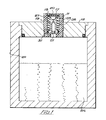
- Fig. 1 is a cross-sectional view of a carbonator bleed valve according to the present invention.
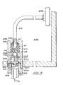
- Fig. 2 is a cross-sectional view of a slow feed valve according to the present invention.
- Fig. 3 is an illustration of the further embodiment of slow feed valve according to the present invention.
- In the examples to be described, it is to be understood that the operation which is taking place is the carbonation of a quantity of water (a batch) in a tank. This tank has an outlet for the water when carbonated, and also there is a means whereby the tank can be refilled. The gas is typically fed in through an inlet and a diffuser which will be submerged in the water whilst carbonation is taking place, the gas flowing from the diffuser and bubbling up through the liquid. Carbonation is the absorption of carbon dioxide into the water from the bubbles as they rise in the water, and from the headspace above the liquid. The lower the temperature at which carbonation takes place, the quicker and more efficient the carbonation process.
- As illustrated by Fig. 1, a bleed valve which includes body 11 is screwed into an appropriate thread in the
lid 13 of a carbonator. At the outer portion of the body 11 is a threadedpart 15 into which an adjustingdisc 17, including arubber seal pad 20, is screwed. Extending downwardly from the adjustingdisc 17 is an elongatedhollow piston 19 with an 0 ring sealing means 31 and which has a fine screen-like structure 21 for example a sintered insert at its inner end. Thepiston member 19 is biased inwardly by aspring 25. The outer end of the valve body 11 contains threecutout 23 beneath the adjustable disc through which the piston can be seen. The outer end ofpiston 19 has a dishedseat 27 with an orifice 28 therein of approximately eighteen thousandths of an inch. As carbon dioxide is admitted to thecarbonator 29 to carbonate a batch ofwater 26 therein,piston 19 is in the position shown, and gas escapes through thescreen portion 21 and through the orifice 18 inseat 27 and is vented out throughcutouts 23 in the body 11. Since the orifice (not shown) admitting gas to the carbonator is larger than orifice 28, pressure builds up in the tank. As pressure builds up in the carbonator tank, thepiston member 19 moves outwardly against the biasingspring 25 untilseat 27 seals againstseal pad 20 both shutting off the venting flow and, at the same time, indicating, by means of a colored portion ofpiston 19 visible throughcutouts 23, that carbonation is complete. (This indication is not absolutely essential.) - The adjusting
disc 17 is generally adjusted to give a carbonation of 3.8 volumes in two minutes. Typically the opening or orifice 28 will have a diameter of 0.018 inches. The carbonator inlet is typically sized at 0.025 in. diameter. At 45 psi this permits drawing 5 ounces of water (through a not shown outlet of the carbonator) in six seconds and replacement with gas. With the 0.25 inch inlet and a 0.018 inch outlet, the necessary pressure buildup to cause the automatic seating takes place in about two minutes. - Fig. 2 is a cross-sectional view of an automatic gas feed valve for accomplishing the same purpose, as the arrangement of Fig. 1, namely rapid carbonation of a batch of water in a carbonator tank. The valve includes a body part 41 containing a threaded bore 43 of a first diameter for sealingly attaching a coupling connected to a source of carbon dioxide at a pressure of 45 psi, for example. Inward from this bore is a larger bore in which is piston-
like member 45 with an O-ring sealing means 47 at its circumference is inserted. Pistonmember 45 has at its inner end acylindrical projecting portion 49. From its outer end or inlet end, is a bore 51 of minimum diameter of .035 inches opening up into alarger bore 53 in the projectingportion 49. There is also a side port 55 in the projecting portion having a diameter of approximately .013 inches. - Inserted over the projecting
part 49 and sealing to it is asleeve 57 having an opening 59 aligned with the port 55. The sleeve contains a central opening 61 designed to retain an 0-ring 63. Abiasing spring 65 surrounds thesleeve 57. Adjacent thebore 44 is a threadedbore 67. Inserted into the threadedbore 67 is aplug 69 having a recess 70 at its inner end into whichspring 65 fits. This member biases the spring against thepiston 45 tending to bias the piston in an inward direction.Plug 69 contains an outwardly extendingcylindrical projection 71. Acentral bore 73 extends throughprojection 71 and the main body of theplug 69. At the inner end of bore 73 a central threadedopening 75 is formed along withauxiliary ports 77 in communication with the space formed by thebore 44. Theprojection 71 is threaded externally and is used to thread into the gas diffuser block in the carbonator with which the feed valve is associated. - Inserted at the outer end of the
bore 73 in theprojection 71 is a three-piece check or one way valve. The first piece comprises a plastic part 79 in the form of flanged cylinder with acentral bore 81. The outer diameter of theflange 80 is equal to the inner diameter of thebore 73. At the top of thecylindrical part 83 above flange 80 a valve seat 85 is formed by an annular projection. A commercially available light weight plastic orrubber valve disc 87 seats on this valve seat 85. It is allowed to move within a chamber 89 which is defined by the top of thecylindrical part 83 and a bore in thethird part 91 of this valve. This part is a generally cylindrical piece with afirst bore 93 of the same size as the outer diameter of thecylindrical part 83 of the first valve part and an outer diameter equal to the size ofbore 73.Bore 93 is continued with asmaller bore 95 through to the outside. At the base of thelarger bore 93 are a plurality ofribs 97 which insure that, if thevalve disc 87 seats against the inner end of thebore 93, there will still be passages to thebore 95. - Threaded into the
bore 75 of theplug member 69 is afurther plug 101 with aconical end 103. In a normal position shown, theconical part 103 is spaced from the 0-ring 63. The amount of spacing can be adjusted by adjusting the distance whichmember 101 is threaded into thebore 75. - In operation, gas at 45 psi will act against the
piston 45 as indicated byarrows 105. Gas will also flow in the direction ofarrow 107 into the bore 51. At this point the pressure inside the carbonator is essentially zero and the difference in pressure will drive thepiston 45, against the biasing force of thespring 65, causing theconical portion 103 to seat against the 0-ring 63. Flow will now be through the restricted radial passage 55. As described in the aforementioned patent application, the carbonator will include diffusers, and by means of the gas slowly passing through the radial passage 55, then through theopening disc 87 and out thepassage 95 the gas then flows into the diffusers and from the diffusers into the water being carbonated. - After about two minutes, the pressure within the carbonator builds up to about 35 psi. Generally the
member 101 should be positioned so that, with a 10 psi difference in pressure acrosspiston 45,portion 103 will unseat fromring 63, and gas can flow through the gap between theconical portion 103 and the 0-ring 63 and vent out along the same path. If the restricted ports were not present, the carbonator would come up to its full pressure in 15 to 20 seconds. With the valve of Fig. 2, this is delayed to approximately 2 minutes. After these 2 minutes, carbonation is at a reasonably high level. After about 3 to 5 minutes carbonation is at an optimum level. On the other hand with the carbonator described in my aforementioned application, full carbonation took 12 to 15 minutes. - It would be possible to accomplish the same thing as is done with the feed valve or bleed valve, with a 0.13 inch orifice into the carbonator and no valve. However, if this was done, when dispensing it would be impossible to replace the gas in the head space above the water, which is needed for dispensing the water, fast enough. With the embodiment of Fig. 2, once the water is carbonated, the piston will be in the position shown, away from the
conical surface 103, and, as carbonated water is dispensed, there will be a free flow of gas to replace the volume which is dispensed and to thereby maintain the necessary pressure within the carbonator to continue carrying out dispensing. At this point, a slow feed or slow bleed is no longer needed since the water in the carbonator is already carbonated, i.e., this is a batch carbonator. Only after the carbonated water is used up and the process is repeated with a new supply of fresh water is it necessary to carry out the slow feeding or slow bleeding to quickly and effectively carbonate the new supply of water. - Furthermore, opening up the gas passage after two minutes results in an influx of carbon dioxide at that time, which aids in the carbonation of the water.
- Fig. 3 illustrates a further embodiment of a carbonator slow feed valve according to the present invention. As illustrated, the valve includes a
body part 201. The body part contains aprojection 271 corresponding to theprojection 71 of Fig. 2. Inserted therein are the same check valve elements as described above in connection with Fig. 2. Amember 203 corresponding in general terms to themember 101 is threaded into aninternal bore 205 inmember 201.Member 201 contains, on the other side ofbore 205 bores 207 and 209 of increasingly larger size.Bore 209 is threaded. At the ledge formed between thebores 207 and 209 aflexible diaphragm 213 is inserted.Diaphragm 213 is sealingly held at its edges by a threaded plug 215 which also contains a central threaded bore 217 into which an inlet fitting 219 for inlet of carbon dioxide is sealingly inserted. -
Diaphragm 213 has a backing ring member 221. A hole 224 is formed through member 221 anddiaphragm 213 and has a diameter of .025 in., for example.Part 203 has acentral bore 223 of diameter .013 inches, for example. A plurality ofpassages 225 are formed in the body coupling the space formed bybore 207 to the other side of themember 203 and thus to the inlet of the check valve. In the position shown, flow is through the central opening 224 in the diaphragm and thepassages 225 to the check valve and then to atube 231 leading to agas diffuser 233.Tube 231 has a flaredend 234 held against agasket 235 by anut 237. - When the carbonating process begins, as with the embodiment of Fig. 2, there will be a large pressure differential on the two sides of
diaphragm 213, as the high pressure gas is introduced throughpipe 219. Since the gas cannot get through the small bore 224 to immediately equalize this, thediaphragm 213 will be deflected toward themember 203 and will seal thereagainst. This position is shown in dotted lines. Now, the gas is forced to flow through thenarrower passage 223 and eventually to thetube 231,diffuser 233 and into thewater 236 in the carbonator and the flow will be restricted in the manner described above. When the pressure in the carbonator reaches a differential corresponding to the spring constant of the diaphragm, the diaphragm will move away from themember 223 and the gas can flow throughdiaphragm 213, and thelarge passages 225 totube 231. The position of themember 203 is adjustable so as to adjust the differential pressure at which the diaphragm will separate frommember 203. Alernatively or additionally, aspring 204 may be used to assist the diaphragm movement away from the seat.
Claims (14)
Priority Applications (1)
| Application Number | Priority Date | Filing Date | Title |
|---|---|---|---|
| AT84113247T ATE56591T1 (en) | 1983-11-10 | 1984-11-03 | PROCESS AND DEVICE FOR BATCH CARBONATION. |
Applications Claiming Priority (2)
| Application Number | Priority Date | Filing Date | Title |
|---|---|---|---|
| US06/550,455 US4564483A (en) | 1983-11-10 | 1983-11-10 | Method and apparatus for batch carbonating |
| US550455 | 1983-11-10 |
Publications (3)
| Publication Number | Publication Date |
|---|---|
| EP0145918A2 true EP0145918A2 (en) | 1985-06-26 |
| EP0145918A3 EP0145918A3 (en) | 1988-08-10 |
| EP0145918B1 EP0145918B1 (en) | 1990-09-19 |
Family
ID=24197250
Family Applications (1)
| Application Number | Title | Priority Date | Filing Date |
|---|---|---|---|
| EP84113247A Expired - Lifetime EP0145918B1 (en) | 1983-11-10 | 1984-11-03 | Method and apparatus for batch carbonating |
Country Status (8)
| Country | Link |
|---|---|
| US (1) | US4564483A (en) |
| EP (1) | EP0145918B1 (en) |
| JP (1) | JPH0790155B2 (en) |
| AT (1) | ATE56591T1 (en) |
| AU (1) | AU578911B2 (en) |
| CA (1) | CA1265042A (en) |
| DE (1) | DE3483248D1 (en) |
| ES (2) | ES8603251A1 (en) |
Cited By (2)
| Publication number | Priority date | Publication date | Assignee | Title |
|---|---|---|---|---|
| AT401597B (en) * | 1993-05-07 | 1996-10-25 | Eduard Wintner | DEVICE FOR PUTTING CARBON DIOXIDE INTO DRINKING WATER |
| US7198744B2 (en) | 2002-08-06 | 2007-04-03 | The Goodyear Tire & Rubber Company | Preparation of co-extruded multi-layered rubber composite and use as component of a tire |
Families Citing this family (11)
| Publication number | Priority date | Publication date | Assignee | Title |
|---|---|---|---|---|
| US4836414A (en) * | 1986-05-02 | 1989-06-06 | The Coca-Cola Company | Premix dispensing system |
| US4850269A (en) * | 1987-06-26 | 1989-07-25 | Aquatec, Inc. | Low pressure, high efficiency carbonator and method |
| US4940164A (en) * | 1987-06-26 | 1990-07-10 | Aquatec | Drink dispenser and method of preparation |
| US4859376A (en) * | 1987-06-26 | 1989-08-22 | Aquatec | Gas-driven carbonator and method |
| US5002201A (en) * | 1988-09-14 | 1991-03-26 | Aquatec Inc. | Bottled water cooler apparatus and method |
| KR960700427A (en) * | 1993-01-09 | 1996-01-20 | 래리 시이 코스켈라 | SAFETY SHUT-OFF GAS LINES |
| BR9812732A (en) | 1997-10-08 | 2000-08-22 | Minnesota Mining & Mfg | Dispensing valve cover |
| US6223791B1 (en) | 1999-10-21 | 2001-05-01 | 3M Innovative Properties Company | Gravity feed fluid dispensing valve |
| US6450214B1 (en) | 2001-08-31 | 2002-09-17 | 3M Innovative Properties Company | Gravity feed fluid dispensing valve |
| US9902054B2 (en) * | 2014-04-15 | 2018-02-27 | Illinois Tool Works Inc. | Embedded regulator for pneumatic nailer supplemental air tank |
| US11566715B1 (en) * | 2021-07-06 | 2023-01-31 | Saudi Arabian Oil Company | Preventing an over pressure condition with a mechanical shutdown valve |
Citations (5)
| Publication number | Priority date | Publication date | Assignee | Title |
|---|---|---|---|---|
| US3752452A (en) * | 1971-06-30 | 1973-08-14 | F Iannelli | Gas-operated carbonating apparatus |
| FR2428613A1 (en) * | 1978-06-13 | 1980-01-11 | Vdr Co Srl | Pressure vessel installation for carbonating water for drinks - uses submerged gas diffuser of porous calcined stone |
| US4298551A (en) * | 1978-08-02 | 1981-11-03 | Thorn Svenska A.B. | Appliance for making an aerated beverage |
| US4313897A (en) * | 1980-01-30 | 1982-02-02 | Bruce Garrard | Gas and liquid admixing system |
| US4399744A (en) * | 1981-04-06 | 1983-08-23 | Ralph Ogden | Beverage carbonator device |
Family Cites Families (13)
| Publication number | Priority date | Publication date | Assignee | Title |
|---|---|---|---|---|
| US1500283A (en) * | 1922-06-21 | 1924-07-08 | Hugh S Stinson | Carbonating apparatus |
| US2117271A (en) * | 1937-08-17 | 1938-05-17 | Siphonator Inc | Combined siphon bottle and carbonator |
| US3572550A (en) * | 1968-10-14 | 1971-03-30 | Eaton Yale & Towne | Method of and apparatus for carbonating, having intersecting streams of gas and liquid |
| US3780198A (en) * | 1971-06-07 | 1973-12-18 | Crown Cork & Seal Co | System for carbonating beverages |
| JPS5225111B2 (en) * | 1972-08-21 | 1977-07-05 | ||
| JPS5016873A (en) * | 1973-06-20 | 1975-02-21 | ||
| US4187262A (en) * | 1978-04-26 | 1980-02-05 | The Cornelius Company | Carbonator and liquid level control |
| US4316409A (en) * | 1979-10-10 | 1982-02-23 | General Foods Corporation | Carbonated beverage container |
| US4304736A (en) * | 1980-01-29 | 1981-12-08 | The Coca-Cola Company | Method of and apparatus for making and dispensing a carbonated beverage utilizing propellant carbon dioxide gas for carbonating |
| US4300923A (en) * | 1980-04-07 | 1981-11-17 | Mojonnier Bros. Co. | Deaerator system having positive pressure indicating means |
| US4323090A (en) * | 1980-05-19 | 1982-04-06 | Bronardi Inc. | Apparatus for aerating liquids |
| US4481986A (en) * | 1982-09-13 | 1984-11-13 | Meyers Louis B | Method and apparatus for making carbonated beverages |
| US4482509A (en) * | 1983-03-04 | 1984-11-13 | Gerlach Industries, Inc. | Carbonating apparatus |
-
1983
- 1983-11-10 US US06/550,455 patent/US4564483A/en not_active Expired - Lifetime
-
1984
- 1984-11-03 DE DE8484113247T patent/DE3483248D1/en not_active Expired - Lifetime
- 1984-11-03 AT AT84113247T patent/ATE56591T1/en active
- 1984-11-03 EP EP84113247A patent/EP0145918B1/en not_active Expired - Lifetime
- 1984-11-07 AU AU35197/84A patent/AU578911B2/en not_active Ceased
- 1984-11-08 ES ES537562A patent/ES8603251A1/en not_active Expired
- 1984-11-09 CA CA000467527A patent/CA1265042A/en not_active Expired - Lifetime
- 1984-11-10 JP JP59236002A patent/JPH0790155B2/en not_active Expired - Lifetime
-
1985
- 1985-09-13 ES ES546968A patent/ES8605630A1/en not_active Expired
Patent Citations (6)
| Publication number | Priority date | Publication date | Assignee | Title |
|---|---|---|---|---|
| US3752452A (en) * | 1971-06-30 | 1973-08-14 | F Iannelli | Gas-operated carbonating apparatus |
| FR2428613A1 (en) * | 1978-06-13 | 1980-01-11 | Vdr Co Srl | Pressure vessel installation for carbonating water for drinks - uses submerged gas diffuser of porous calcined stone |
| US4298551A (en) * | 1978-08-02 | 1981-11-03 | Thorn Svenska A.B. | Appliance for making an aerated beverage |
| US4298551B1 (en) * | 1978-08-02 | 1986-07-22 | ||
| US4313897A (en) * | 1980-01-30 | 1982-02-02 | Bruce Garrard | Gas and liquid admixing system |
| US4399744A (en) * | 1981-04-06 | 1983-08-23 | Ralph Ogden | Beverage carbonator device |
Cited By (2)
| Publication number | Priority date | Publication date | Assignee | Title |
|---|---|---|---|---|
| AT401597B (en) * | 1993-05-07 | 1996-10-25 | Eduard Wintner | DEVICE FOR PUTTING CARBON DIOXIDE INTO DRINKING WATER |
| US7198744B2 (en) | 2002-08-06 | 2007-04-03 | The Goodyear Tire & Rubber Company | Preparation of co-extruded multi-layered rubber composite and use as component of a tire |
Also Published As
| Publication number | Publication date |
|---|---|
| ES537562A0 (en) | 1985-12-16 |
| EP0145918A3 (en) | 1988-08-10 |
| ES8605630A1 (en) | 1986-03-16 |
| ATE56591T1 (en) | 1990-10-15 |
| AU3519784A (en) | 1985-05-16 |
| CA1265042A (en) | 1990-01-30 |
| ES546968A0 (en) | 1986-03-16 |
| EP0145918B1 (en) | 1990-09-19 |
| DE3483248D1 (en) | 1990-10-25 |
| ES8603251A1 (en) | 1985-12-16 |
| US4564483A (en) | 1986-01-14 |
| JPH0790155B2 (en) | 1995-10-04 |
| JPS60168521A (en) | 1985-09-02 |
| AU578911B2 (en) | 1988-11-10 |
Similar Documents
| Publication | Publication Date | Title |
|---|---|---|
| EP0145918B1 (en) | Method and apparatus for batch carbonating | |
| US3966091A (en) | Carbonated beverage dispenser having diffuser assembly | |
| US4867209A (en) | Portable hand holdable carbonating apparatus | |
| US4720076A (en) | Dispense tap | |
| US9919910B2 (en) | Fluid pressurization and dispensing system | |
| US4222972A (en) | Method and means for carbonating liquids in situ | |
| US4482509A (en) | Carbonating apparatus | |
| US3948419A (en) | Beverage fluid flow controller | |
| US20090025802A1 (en) | Constant flow valve | |
| GB1357994A (en) | System for carbonating beverages | |
| US4350503A (en) | Fluid flow metering device | |
| US5038976A (en) | Method of and dispensing head for increased carbonation | |
| US1964345A (en) | Aerating device | |
| US3727844A (en) | Dispensing apparatus | |
| US3460555A (en) | Pressure regulator construction | |
| US20090217822A1 (en) | Method and apparatus for controlling the amount of dissolved gas in a liquid | |
| JPH06506151A (en) | Discharge valve for melt air flotation | |
| WO1992022025A1 (en) | Flow control apparatus | |
| US4953593A (en) | Fluid mixing apparatus for producing variably carbonated water | |
| US3269598A (en) | Pressure regulator | |
| US1713787A (en) | Carbonating apparatus | |
| US3556356A (en) | Device for dispensing carbonated beverages | |
| US2179611A (en) | Draft arm nozzle | |
| US1500283A (en) | Carbonating apparatus | |
| US4940165A (en) | Method of and dispensing head for increased carbonation |
Legal Events
| Date | Code | Title | Description |
|---|---|---|---|
| PUAI | Public reference made under article 153(3) epc to a published international application that has entered the european phase |
Free format text: ORIGINAL CODE: 0009012 |
|
| AK | Designated contracting states |
Designated state(s): AT BE CH DE FR GB IT LI LU NL SE |
|
| PUAL | Search report despatched |
Free format text: ORIGINAL CODE: 0009013 |
|
| AK | Designated contracting states |
Kind code of ref document: A3 Designated state(s): AT BE CH DE FR GB IT LI LU NL SE |
|
| 17P | Request for examination filed |
Effective date: 19880713 |
|
| 17Q | First examination report despatched |
Effective date: 19890904 |
|
| ITF | It: translation for a ep patent filed |
Owner name: FIAMMENGHI - DOMENIGHETTI |
|
| GRAA | (expected) grant |
Free format text: ORIGINAL CODE: 0009210 |
|
| AK | Designated contracting states |
Kind code of ref document: B1 Designated state(s): AT BE CH DE FR GB IT LI LU NL SE |
|
| REF | Corresponds to: |
Ref document number: 56591 Country of ref document: AT Date of ref document: 19901015 Kind code of ref document: T |
|
| ET | Fr: translation filed | ||
| REF | Corresponds to: |
Ref document number: 3483248 Country of ref document: DE Date of ref document: 19901025 |
|
| PLBE | No opposition filed within time limit |
Free format text: ORIGINAL CODE: 0009261 |
|
| STAA | Information on the status of an ep patent application or granted ep patent |
Free format text: STATUS: NO OPPOSITION FILED WITHIN TIME LIMIT |
|
| 26N | No opposition filed | ||
| ITTA | It: last paid annual fee | ||
| EPTA | Lu: last paid annual fee | ||
| EAL | Se: european patent in force in sweden |
Ref document number: 84113247.5 |
|
| PGFP | Annual fee paid to national office [announced via postgrant information from national office to epo] |
Ref country code: GB Payment date: 19960926 Year of fee payment: 13 |
|
| PGFP | Annual fee paid to national office [announced via postgrant information from national office to epo] |
Ref country code: LU Payment date: 19961001 Year of fee payment: 13 |
|
| PGFP | Annual fee paid to national office [announced via postgrant information from national office to epo] |
Ref country code: BE Payment date: 19961003 Year of fee payment: 13 |
|
| PGFP | Annual fee paid to national office [announced via postgrant information from national office to epo] |
Ref country code: CH Payment date: 19961107 Year of fee payment: 13 |
|
| PGFP | Annual fee paid to national office [announced via postgrant information from national office to epo] |
Ref country code: SE Payment date: 19961118 Year of fee payment: 13 |
|
| PGFP | Annual fee paid to national office [announced via postgrant information from national office to epo] |
Ref country code: AT Payment date: 19961126 Year of fee payment: 13 |
|
| PGFP | Annual fee paid to national office [announced via postgrant information from national office to epo] |
Ref country code: FR Payment date: 19961129 Year of fee payment: 13 |
|
| PGFP | Annual fee paid to national office [announced via postgrant information from national office to epo] |
Ref country code: NL Payment date: 19961130 Year of fee payment: 13 |
|
| PGFP | Annual fee paid to national office [announced via postgrant information from national office to epo] |
Ref country code: DE Payment date: 19970109 Year of fee payment: 13 |
|
| PG25 | Lapsed in a contracting state [announced via postgrant information from national office to epo] |
Ref country code: LU Free format text: LAPSE BECAUSE OF NON-PAYMENT OF DUE FEES Effective date: 19971103 Ref country code: GB Free format text: LAPSE BECAUSE OF NON-PAYMENT OF DUE FEES Effective date: 19971103 Ref country code: AT Free format text: LAPSE BECAUSE OF NON-PAYMENT OF DUE FEES Effective date: 19971103 |
|
| PG25 | Lapsed in a contracting state [announced via postgrant information from national office to epo] |
Ref country code: SE Free format text: LAPSE BECAUSE OF NON-PAYMENT OF DUE FEES Effective date: 19971104 |
|
| PG25 | Lapsed in a contracting state [announced via postgrant information from national office to epo] |
Ref country code: LI Free format text: LAPSE BECAUSE OF NON-PAYMENT OF DUE FEES Effective date: 19971130 Ref country code: FR Free format text: THE PATENT HAS BEEN ANNULLED BY A DECISION OF A NATIONAL AUTHORITY Effective date: 19971130 Ref country code: CH Free format text: LAPSE BECAUSE OF NON-PAYMENT OF DUE FEES Effective date: 19971130 Ref country code: BE Free format text: LAPSE BECAUSE OF NON-PAYMENT OF DUE FEES Effective date: 19971130 |
|
| BERE | Be: lapsed |
Owner name: CADBURY SCHWEPPES P.L.C. Effective date: 19971130 |
|
| PG25 | Lapsed in a contracting state [announced via postgrant information from national office to epo] |
Ref country code: NL Free format text: LAPSE BECAUSE OF NON-PAYMENT OF DUE FEES Effective date: 19980601 |
|
| GBPC | Gb: european patent ceased through non-payment of renewal fee |
Effective date: 19971103 |
|
| REG | Reference to a national code |
Ref country code: CH Ref legal event code: PL |
|
| PG25 | Lapsed in a contracting state [announced via postgrant information from national office to epo] |
Ref country code: DE Free format text: LAPSE BECAUSE OF NON-PAYMENT OF DUE FEES Effective date: 19980801 |
|
| EUG | Se: european patent has lapsed |
Ref document number: 84113247.5 |
|
| NLV4 | Nl: lapsed or anulled due to non-payment of the annual fee |
Effective date: 19980601 |
|
| REG | Reference to a national code |
Ref country code: FR Ref legal event code: ST |