EP0146700A2 - Vorrichtung zur Herstellung von Gegenständen aus einer Materialbahn einer thermoplastischen Folie und die Verwendung derselben zur Herstellung von Behälterteilen - Google Patents
Vorrichtung zur Herstellung von Gegenständen aus einer Materialbahn einer thermoplastischen Folie und die Verwendung derselben zur Herstellung von Behälterteilen Download PDFInfo
- Publication number
- EP0146700A2 EP0146700A2 EP84111673A EP84111673A EP0146700A2 EP 0146700 A2 EP0146700 A2 EP 0146700A2 EP 84111673 A EP84111673 A EP 84111673A EP 84111673 A EP84111673 A EP 84111673A EP 0146700 A2 EP0146700 A2 EP 0146700A2
- Authority
- EP
- European Patent Office
- Prior art keywords
- web
- material web
- heating
- film
- punching
- Prior art date
- Legal status (The legal status is an assumption and is not a legal conclusion. Google has not performed a legal analysis and makes no representation as to the accuracy of the status listed.)
- Granted
Links
Images


Classifications
-
- B—PERFORMING OPERATIONS; TRANSPORTING
- B29—WORKING OF PLASTICS; WORKING OF SUBSTANCES IN A PLASTIC STATE IN GENERAL
- B29C—SHAPING OR JOINING OF PLASTICS; SHAPING OF MATERIAL IN A PLASTIC STATE, NOT OTHERWISE PROVIDED FOR; AFTER-TREATMENT OF THE SHAPED PRODUCTS, e.g. REPAIRING
- B29C51/00—Shaping by thermoforming, i.e. shaping sheets or sheet like preforms after heating, e.g. shaping sheets in matched moulds or by deep-drawing; Apparatus therefor
- B29C51/26—Component parts, details or accessories; Auxiliary operations
- B29C51/44—Removing or ejecting moulded articles
- B29C51/445—Removing or ejecting moulded articles from a support after moulding, e.g. by cutting
-
- B—PERFORMING OPERATIONS; TRANSPORTING
- B29—WORKING OF PLASTICS; WORKING OF SUBSTANCES IN A PLASTIC STATE IN GENERAL
- B29C—SHAPING OR JOINING OF PLASTICS; SHAPING OF MATERIAL IN A PLASTIC STATE, NOT OTHERWISE PROVIDED FOR; AFTER-TREATMENT OF THE SHAPED PRODUCTS, e.g. REPAIRING
- B29C51/00—Shaping by thermoforming, i.e. shaping sheets or sheet like preforms after heating, e.g. shaping sheets in matched moulds or by deep-drawing; Apparatus therefor
- B29C51/26—Component parts, details or accessories; Auxiliary operations
- B29C51/42—Heating or cooling
- B29C51/421—Heating or cooling of preforms, specially adapted for thermoforming
Definitions
- the invention relates to a device for the production of objects from a material web of a thermoplastic film and the use thereof for the production of container parts.
- the aim of the device according to the invention is to create solutions to the problems mentioned.
- the task in particular when processing multilayer films is to bring the film quickly and uniformly to the necessary softening state.
- none of the layers may be exposed to a temperature that is too high for them, since otherwise the quality of the shaped objects may suffer.
- internal, non-metallic barrier layers of the film are ge endangers.
- hot air heating is time-consuming and correspondingly requires space, and has a low thermal efficiency
- the more effective radiation heating with large-area heating has the disadvantage of uneven heating of the film as a result of local air convection between the film and the radiator. It is also difficult to adjust because the heating depends on the radiation absorption properties of the film, which are strongly influenced by the changing surface properties and storage conditions of the film. The temperature profile in the film is therefore difficult to control.
- the heating device is designed as a combination of a contact heater and a radiation heater.
- the contact heater is preferably connected upstream of the radiant heater in the web transport direction.
- the contact heater has a lower and an upper heating plate which can be brought into contact with the upper or lower side of the material web.
- a temperature profile is first impressed on the film, which decreases on both sides from the surface to the center.
- Sensitive, inner barrier layers of a multi-layer film are thus available Protected from overheating.
- the heating takes place only up to a point at which the surface temperatures of the foil allow a perfect detachment from the heating plates.
- the material web part provided with the uniform heat profile over the web surface is then subsequently put into a softening state suitable for shaping by the radiant heating, wherein essentially only an increase in the existing thermal profile is caused by the radiant heating. Influences of convection etc. therefore appear much less because the time spent in the radiation field is shortened compared to conventional radiation heating and the radiation field can be reduced.
- this heating device is preferably used for processing a polypropylene multilayer film with an inner barrier layer made of vinylidene chloride-vinyl chloride copolymers (Saran), since the barrier layer has a lower softening or melting temperature than the outer layer.
- an inner barrier layer made of vinylidene chloride-vinyl chloride copolymers (Saran)
- the barrier layer has a lower softening or melting temperature than the outer layer.
- it is not limited to this.
- the punch-out device has a pre-cutting point and a resharpened, centered circumferential punching point, the objects formed from the material web being separated from one another at least in some areas in the pre-cutting point be punched into their final circumference in the circumferential punching point after fitting into a centering arrangement.
- the individual objects can be fitted into the centering device independently of one another, so that individual positioning is possible independently of any irregular dimensional shrinkage in the material web.
- the positioned objects can then be brought to their exact circumferential shape with a punching knife adjusted to the centering device.
- the transport device solves the above-mentioned problem in that it has drive wheels connected to a common drive on both sides along the material web, each of which is supported against an associated sprung or fixed roller, the material web between the drive wheels and the rollers being detectable.
- the drive wheels are preferably toothed on their periphery and each roller is ge with an adjustable bias against the associated driving wheel, the engagement surface of the wheel being dimensioned such that it at least partially penetrates into the material web to create line contact at the given pretension.
- the drive wheels can be arranged at an angle to the direction of transport. This drive allows an exactly maintainable stride length even with intermittent drive.
- thermoplastic film which contains the aforementioned heating device, punching device and transport device in combination, will now be described with reference to the accompanying drawing. According to the above and following explanations, however, each of these devices can also be used without the other two.
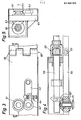
- the device shown which is first described with reference to the first two figures, has essentially five successive processing stations 1 to 5.
- a roll support arrangement for a material roll of known construction is provided (not shown). It is for material rolls with a width of 560 mm, for example and a diameter of 1200 mm. Since the material is transported through the device in steps, a compensation point is arranged downstream of the roll support arrangement, where one step length of the material strip can be temporarily stored. The rolling speed of the roll can thus remain essentially constant, and the rolling speed can be adapted to the respective roll diameter by means of light barriers.
- the material web is then gripped by the lateral transport device 6 and conveyed in steps by the device.
- the first processing point is a contact heater 1 with two heated plates 10 and 11, between which the film 7 can be clamped.
- the electrical heating of the plates can be regulated independently of one another to an adjustable setpoint.
- the two plates 10, 11 can intermittently clamp and release the film 7 with a selectable pressing pressure.
- at least one of the plates, in the figure the upper plate 10, is provided with a corresponding hydraulic or pneumatic system.
- the temperature and the contact pressure of the plates are set so that the heating required for the respective material takes place in the intended step duration of, for example, 4 seconds.
- the sizes mentioned are set so that the desired temperature profile is formed in the film.
- the film In the contact heater, the film is heated uniformly over essentially the entire working surface, but not yet to the softening point. This prevents the film from sticking to the plates 10, 11.
- the material web reaches the radiation heater 2 in the next working step.
- This consists of medium-wave radiators 21 arranged on both sides of the film 7, which are arranged in a housing 22 to reduce air convection.
- the remaining heating to the softening point of the film can thus take place within the available step time.
- the transverse expansion of the film that occurs in this area which is exacerbated by the effect of its own weight, can lead to a sag, through which the distances between the film and the radiator are changed.
- two measures can be provided: one consists in supporting the film in its central area by at least one accompanying support element.
- two traveling wire ropes 23 are provided for this purpose, which are guided from below to the film via deflection or drive rollers 24 before the radiant heating and support this up to the shaping device 3.
- a local transverse stretching can be effected by means of a transport device in the area of the radiant heating, as will be explained in detail later.
- the two-stage heating described ensures optimum heating, in particular for multilayer films. While the contact heating of the film quickly and energy-saving imprints a temperature profile, the radiant heating finally brings the stable cover films to the ideal softening temperature without damaging the inner (barrier) films.
- this heater has proven itself for processing a multilayer film, in which a barrier film made of Saran (a vinylidene chloride-vinyl chloride copolymer) is bonded to polypropylene outer films by means of an adhesion promoter, the total film thickness being approx. 900 pm.
- Saran a vinylidene chloride-vinyl chloride copolymer
- an adhesion promoter the total film thickness being approx. 900 pm.
- other barrier polymers such as EVOH can also be used.
- the shaping can take place in a subsequent thermoforming device 3 in a manner known per se. This is designed in such a way that it is possible to work with vacuum deformation both in the positive and in the negative process, and on the other hand it is also possible to use pressure to carry out air deformation.
- the punching device can be integrated directly in the thermoforming device or, as in the exemplary embodiment described, can be carried out in one or more subsequent work steps.
- a toggle arrangement (not shown) allows the molds to be opened and closed.
- 1 is designed for compressed air deformation.
- recesses 33 are formed for the simultaneous shaping of six shell-like container parts.
- Channels for the wire cables 23 are provided between the recesses 33.
- the individual recesses can be closed airtight by means of an upper plate 34, after which the shells are formed by means of compressed air.
- the punching device is separated from the thermoforming device so that the film can cool down sufficiently before punching out, otherwise the still soft barrier film adheres to the punching tool and pulls threads.
- the punching device is designed in such a way that, despite irregular shrinkage of the film when cooling after thermoforming, the same, defined outer circumference is achieved for each container.
- the material web between the shaped containers is partially separated so that these containers still carried by the material web can be positioned independently of one another in the actual circumferential punching point.
- a pre-punching point 4 and a subsequent circumferential punching point 5 are provided.
- the pre-punching point 4 can also be used for the final circumferential punching if the processed film allows this. In the case of foils with strong shrinkage, however, it is only used for pre-punching and leaving Predetermined breaking points 21 between the individual container parts or the material web. It consists of an upper and a lower stamped part 42 and 43, both of which are retractable from the material web. In the upper stamped part 42, which can be heated, a cutting edge 44 is inserted in accordance with the desired pre-punching and works against corresponding surfaces on the lower stamped part 43. After the pre-punching, the pre-shaped container parts connected to the material strip at the predetermined breaking points reach the circumferential punching point 5 in the next working step.
- the container parts are pressed first by Brechstem p el 51 broken out of the material strip 7 and to understand or handle in a lower centering arrangement 52nd Immediately after centering, the circumferential punching is carried out by a knife 54 arranged on an upper punch 53, which corresponds to the exact circumference of the container parts. The container parts are then carried away in a conventional manner (not shown) and stacked on a stacking station 8. The remaining strip material is rolled up on the exit side (not shown).
- FIGS. 6 to 8 show a second exemplary embodiment, which shows a further variant of the punching out of the shells following the thermoforming device 3.
- the material web 7 with the shells molded therein is first separated by cutting rollers 70, 71 between longitudinal rows of shells into individual webs, so that each of the individual webs can be moved transversely to the transport direction independently of the others for lateral positioning of the shells during the subsequent circumferential punching in the circumferential punching point 5 '.
- the cutting rollers 70, 71 are profiled (FIG. 8) such that a narrow strip is cut out of the material web during the separation.
- After the cutting rollers 70, 71 is a roller 72 provided, which pushes the material webs slightly out of the plane.
- the circumferential punching point 5 ' is shown schematically in cross section in FIG. 7 for a single shell. It has a positioning and ejection part 73 arranged under the material web, a stamping part 74 arranged above it and a magazine 75 for the finished punched-out shells. When the material web 7 is transported, the positioning and ejection part 73 and the stamping part 74 remain lifted off the web.
- the positioning and ejection part 74 is first raised from below against the shells, which are aligned in the corresponding recesses 76 owing to their lateral and longitudinally acting shaft. Thereafter, the circumferential punching is carried out by lowering the stamped part 74. The punched-out shells are then moved by means of an ejector 77 through the stamped part 74 into the magazine 75 located at the top, and are brought there from below to the respective stack of shells which is held in the magazine by elastic projections 78 . After the ejector 77 is withdrawn, the work cycle is ended. The remaining strip material is rolled up on a roll 79.
- the described punching methods are suitable, regardless of the design of the preceding heating device, for the exact circumferential punching of thermoformed objects, which change in their masses when cooled, by means of centering these undesirable and difficult-to-see effects can be eliminated.
- the transport of the material web through the device is accomplished with a device 6, which can be seen in detail from FIGS. 3 to 5.
- the transport device 6 runs along the entire length of the material web on both sides Device and engages on the edge of the material web lying outside the shaping zone.
- the transport device now has drive wheels 61 distributed along the device, each of which is supported against a corresponding support roller 62.
- the material web 7 is gripped between the drive wheels and the support rollers, as can best be seen in FIG. 5.
- Each support roller 62 is loaded with an adjustable preload against its drive wheel 61. This, as shown in Fig. 3, hfitun by the up g of the support roller 62 can be achieved on a pivot lever 62 which by means of a pneumatic cylinder is charged Kclben owned 64th
- the support rollers 62 are preferably provided with ball bearings in order to achieve low transport resistance.
- the driving wheels have fine teeth on their wedge-shaped circumference to increase the friction against the film.
- the contact surface on the circumference is matched to the load on the support roller 62 in such a way that the drive wheels partially penetrate into the material web in order to create a line engagement.
- the wedge-shaped design of the engagement area of the drive wheels also prevents the material strip from sliding out during the processing steps in which lateral forces can occur in the material strip.
- the drive wheels are driven rigidly by one drive shaft 66 each via two bevel gears 67. The rigid drive ensures exact compliance with the selected step length and requires little maintenance.
- the transport device is fastened in a support element 65, which on a machine frame (not ge shows) is attached.
- the support element 65 can be provided with a hinge 69 at the required points and the drive shaft 66 with a toothed coupling 68 serving as a spherical joint be.
- hinges or joints are provided before and after the radiant heater 2, so that in this area the drive wheels 62 can be arranged at an angle to the direction of transport, with the corresponding transverse conveyance as a rim.
- the transport device 6 described can not only be used in connection with the system parts described above, but is generally suitable for the material web transport.
- the device described here for producing objects from a material web of a thermoplastic film is particularly suitable for processing multilayer films with heat-sensitive inner layers.
- a film is, for example, a laminate with a thickness of 900 ⁇ m made of polypropylene cover films which are bonded to an internal barrier layer made of Saran by means of an adhesion promoter.
- Such relatively thick multilayer films which are suitable for the production of food containers because of the good barrier properties, were previously difficult to process because of the difficult thermal behavior of the film.
- the present device now allows this in a flawless manner, which is particularly due to the two-step off design of the heating and punching devices is returned.
Abstract
Description
- Die Erfindung betrifft eine Vorrichtung zur Herstellung von Gegenständen aus einer Materialbahn einer thermoplastischen Folie und die Verwendung derselben zur Herstellung von Behälterteilen.
- Im Zusammenhang mit Vorrichtungen dieser Art treten insbesondere bei der Verarbeitung von Materialien mit ungünstigem thermischen Verhalten Probleme bei der Erwärmung sowie dem Ausstanzen der geformten Gegenstände aus der Materialbahn auf. Ferner besteht bei solchen, aber auch den übrigen in Frage stehenden Materialien das Problem des Materialbahntransportes durch die Vorrichtung hindurch, welches bis heute nicht befriedigend gelöst wurde.
- Mit der erfindungsgemässen Vorrichtung wird angestrebt, Lösungen für die genannten Probleme zu schaffen.
- Was zunächst die Aufheizung der Materialbahn anbelangt, so stellt sich insbesondere bei der Verarbeitung von Mehrschichtfolien die Aufgabe, die Folie schnell und gleichförmig auf den notwendigen Erweichungszustand zu bringen. Dabei darf bei unterschiedlichen Erweichungspunkten keine der Schichten einer für sie zu hohen Temperatur ausgesetzt sein, da sonst die Qualität der geformten Gegenstände leiden kann. Insbesondere innenliegende, nichtmetallische Sperrschichten der Folie sind hierbei,gefährdet.
- Unter den bisher bekannten Aufheizverfahren und Vorrichtungen sind zu erwähnen: Heissluftheizung, Strahlungsheizung sowie Kontaktheizung. Während die Heissluftheizung zeitaufwendig und entsprechend raumbedürftig ist, sowie einen kleinen thermischen Wirkungsgrad aufweist, besitzt die wesentliche wirksamere Strahungsheizung bei grossflächiger Heizung den Nachteil ungleichmässiger Erwärmung der Folie in Folge lokaler Luftkonvektion zwischen Folie und Strahler. Sie ist zudem schwierig einzustellen, da die Aufheizung von den Strahlungsabsorptionseigenschaften der Folie abhängen, welche durch wechselnde Oberflächenbeschaffenheit und Lagerbedingungen der Folie stark beeinflusst werden. Das Temperaturprofil in der Folie ist deshalb nur schwer zu kontrollieren.
- Schliesslich ist z.B. aus der CH-PS 598 933 die Kontaktheizung von Folien bekannt geworden. Dabei stellt sich insbesondere das Problem des Anhaftens der Folie, falls sie auf eine zum Tiefziehen ausreichende Temperatur erwärmt werden soll, insbesondere weil die Folienoberflächen rasch die Temperatur der Heizflächen annehmen, während das Folieninnere die nötige Erweichungstemperatur noch nicht erreicht hat.
- Ueberraschenderweise hat sich gezeigt, dass die genannten Probleme dadurch gelöst werden, dass die Aufheizeinrichtung als Kombination einer Kontaktheizung und einer Strahlungsheizung ausgebildet ist. Vorzugsweise ist die Kontaktheizung in Bahntransportrichtung der Strahlungsheizung vorgeschaltet. Die Kontaktheizung besitzt bei einer bevorzugten Ausführung eine untere sowie eine obere Heizplatte, die in Anlage an die Materialbahnober- bzw. Unterseite bringbar sind.
- In der Kontaktheizung wird der Folie zunächst ein Temperaturprofil aufgeprägt, das beidseitig von der Oberfläche zur Mitte hin abnimmt. Empfindliche, innere Sperrschichten einer Mehrschichtfolie werden damit vor Ueberhitzung geschützt. Die Erwärmung erfolgt nur bis zu einem Punkt, bei dem die Oberflächentemperaturen der Folie ein einwandfeies Ablösen von den Heizplatten erlaubt. Der mit dem über die Bahnfläche gleichmässigen Wärmeprofil versehene Materialbahnteil wird danach anschliessend durch die Strahlungsheizung in einen für die Formung geeigneten Erweichungszustand versetzt, wobei durch die Strahlungsheizung im wesentlichen nur eine Anhebung des bestehenden Wäremprofils verursacht wird. Einflüsse der Konvektion etc. treten daher wesentlich weniger in Erscheinung, weil die Aufenthaltszeit im Strahlungsfeld gegenüber herkömmlicher Strahlungsheizung verkürzt wird und das Strahlungsfeld verkleinert werden kann.
- Insbesondere wird diese Heizvorrichtung bevorzugt verwendet für die Verarbeitung einer Polypropylen-Mehrschichtfolie mit einer inneren Sperrschicht aus Vinylidenchlorid-Vinylchlorid-Copolymeren (Saran), da die Sperrschicht eine niedrigere Erweichungs- bzw. Schmelztemperatur aufweist, als die Aussenschicht. Sie ist jedoch nicht hierauf beschränkt.
- Bei Folien der eingangs genannten Art mit ungünstigem thermischen Verhalten tritt ferner nach dem Formen das Problem des massgerechten Ausstanzens der geformten Gegenstände auf. Dies deshalb, weil die noch warme Folie relativ. wenig massstabil ist und insbesondere beim Abkühlen ein nur schwer zu erfassender Schwund auftritt. Um dennoch eine ohne die Produktion hemmende Ruhezeit für die Stabilisierung des Materials massgenaue Ausstanzung zu erzielen, ist erfindungsgemäss vorgesehen, dass die Ausstanzeinrichtung eine Vortrennstelle sowie eine nachgeschlatete, zentrierte Umfangsstanzstelle aufweist, wobei die aus der Materialbahn geformten Gegenstände in der Vortrennstelle mindestens bereichsweise voneinander getrennt und in der Umfangsstanzstelle nach Einpassung in eine Zentrieranordnung auf ihren Endumfang gestanzt werden. Die Vortrennung, bei der Massgenauigkeit nicht erforderlich ist, erlaubt die voneinander unabhängige Einpassung der einzelnen Gegenstände in die Zentriervorrichtung, so dass ein individuelle Positionierung unabhängig von allenfalls unregelmässigem Massschwund in der Materialbahn ermöglicht wird. Die positionierten Gegenstände können dann mit einem auf die Zentriervorrichtung justierten Stanzmesser auf ihre exakte Umfangsform gebracht werden.
- Schliesslich stellt sich beim Verarbeiten von Materialbahnen das Problem des Materialbahntransportes durch die gesamte Anlage. Dies insbesonders dann, wenn sich die Folie bei der Erwärmung in Querrichtung dehnt, was zum Beispiel im Bereich einer Strahlungsheizung durch das Eigengewicht der Folie verstärkt werden kann. Soll in solchen Situationen ein Durchhang der Folie verhindert oder reduziert werden, so ist bereichsweise eine geringfügige Querkomponente der Förderung vorzusehen. Bekannte Transporteinrichtungen arbeiten mit beidseitig der Materialbahn angeordneten Klemmketten oder Stachelketten, die über die gesamte Bahnlänge am Rand angreifen. Solche Kettenanteile haben den Nachteil der ungleichmässigen Verstreckung. Bei intermittierend ablaufenden Arbeitsprozessen ist damit eine Einhaltung exakter Schrittlängen schwierig und unterschiedlichevorschübe auf den beiden Seiten können zu unerwünschten diagonalen Verstreckungen in der Folienbahn führen. Da Ketten nur in einer Ebene umlaufen können, ist es schwierig, eine bereichsweise lokale Querdehnung der Folie zu bewerkstelligen.
- Die erfindungsgemässe Transporteinrichtung löst das genannte Problem dadurch, dass sie beidseitig längs der Materialbahn je an einem gemeinsamen Antrieb angeschlossene Treibräder besitzt, die je gegen eine zugehörige gefederte oder feste Rolle abgestützt sind, wobei die Materialbahn zwischen den Treibrädern und den Rollen erfassbar ist. Die Treibräder sind vorzugsweise an ihrer Peripherie gezahnt und jede Rolle ist mit einer einstellbaren Vorspannung gegen das zugehörige Treibrad belastet, wobei die Eingriffsfläche des rades derart bemessen ist, dass es zur Schaffung eines Linienkontaktes bei der gegebenen Vorspannung mindestens teilweise in die Materialbahn eindringt. Im Bereich, bei dem eine Querdehnung der Folie gewünscht ist, können die Treibräder in einem Winkel zur Transportrichtung angeordnet sein. Dieser Antrieb gestattet auch bei intermittierendem Antrieb eine exakt einhaltbare Schrittlänge.
- Nachfolgend wird nun anhand der beiliegenden Zeichnung ein Ausführungsbeispiel einer Vorrichtung zur Herstellung von Gegenständen aus einer Materialbahn einer thermoplastischen Folie beschrieben, das die vorstehend erwähnte Aufheizeinrichtung, Ausstanzeinrichtung und Transporteinrichtung in Kambination enthält. Nach Massgabe der vorstehenden und nachfolgenden Ausführungen kann jedoch jede dieser Einrichtungen auch ohne die beiden anderen eingesetzt werden.
- Es zeigen:
- Fig. 1 eine schematische Queransicht der Vorrichtung, teilweise im Schnitt, längs der Transportrichtung;
- Fig. 2 eine schematische Aufsicht entsprechend Fig. l;
- Fig. 3 eine Ansicht eines Ausschnittes der Transporteinrichtung quer zur Transportrichtung in der Materialbahnebene;
- Fig. 4 eine Schnittansicht entlang der Linie IV-IV in Fig.3, und
- Fig. 5 eine schematische Schnittansicht längs der Triebachse der Antriebseinrichtung.
- Fig. 6 eine Abwandlung der Trenn- und Umfangsstanzstelle,
- Fig. 7 einen schematischen Schnitt durch die Umfangsstanzstelle von Fig. 6
- Fig. 8 ein Detail der Trennvorrichtung von Fig. 6
- Die dargestellte Vorrichtung, welche zunächst anhand der beiden ersten Figuren beschrieben wind, weist im wesentlichen fünf aufeinanderfolgende Bearbeitungsstationen 1 bis 5 auf. Auf der Eingangsseite (links in den Fig. 1 und 2) ist eine Rollentraganordnung für eine Materialrolle bekannten Aufbaus vorgesehen (nicht dargestellt). Sie ist für Materialrollem einer Breite von beispielsweise 560 mm und einem Durchmesser von 1200 mm vorgesehen. Da der Materialtransport durch die Vorrichtung in Schritten erfolgt, ist der Rollentraganordnung eine Kompensationsstelle nachgeschaltet, wo jeweils eine Schrittlänge des Materialbandes zwischengespeichert werden kann. Die Abrollgeschwindigkeit der Rolle kann damit im wesentlichen stetig bleiben, wobei mittels Lichtschranken die Abrollgeschwindigkeit dem jeweiligen Rollendurchmesser angepasst werden kann. Anschliessend wird die Materialbahn durch die seitliche Transporteinrichtung 6 erfasst und in Schritten durch die Vorrichtung gefördert. Die erste Bearbeitungsstelle ist eine Kontaktheizung 1 mit zwei geheizten Platten 10 und 11, zwischen welchen die Folie 7 einklemmbar ist. Die elektrische Heizung der Platten ist unabhängig voneinander auf einen einstellbaren Sollwert regelbar. Die beiden Platten 10, 11 können mit einem wählbaren Pressdruck die Folie 7 intermittierend einklemmen und wieder freigaben. Zu diesem Zweck ist mindestens eine der Platten, in der Figur die obere Platte 10, mit einer entsprechenden Hydraulik-oder Pneumatik versehen. Die Temperatur sowie der Anpressdruck der Platten werden so eingestellt, dass in der vorgesehenen Schrittdauer von z.B. 4 sec. die für das jeweilige Material notwendige Aufheizung erfolgt. Bei Mehrschichtfolien mit innenliegenden, temperaturempfindlichen Sperrschichten werden die genannten Grössen so eingestellt, dass sich das gewünschte Temperaturprofil in der Folie ausbildet. In der Kontaktheizung wird die Folie über im wesentlichen die gesamteArbeitsfläche gleichmässig erwärmt, jedoch noch nicht bis zum Erweichungspunkt. Ein Kleben der Folie an den Platten 10,11 ist damit ausgeschlossen. Unmittelbar nach der Kontaktheizung 1 gelangt die Materialbahn beim nächsten Arbeitsschritt zur Strahlungsheizung 2. Diese besteht aus beidseitig der Folie 7 angeordneten, mittelwelligen Strahlern 21, die zur Verminderung der Luftkonvektion in einem Gehäuse 22 angeordnet sind.
- Innerhalb der zur Verfügung stehenden Schrittzeit kann damit die restliche Erwärmung auf den Erweichungspunkt der Folie erfolgen. Die in diesem Bereich entstehende Querdehnung der Folie, welche durch die Einwirkung des Eigengewichts noch verstärkt wird, kann zu einem Durchhang führen, durch welchen die Abstände zwischen Folie und Strahler verändert werden. Um diesen Durchhang aufzunehmen bzw. zu reduzieren, können zwei Massnahmen vorgesehen sein: Die eine besteht in der Stützung der Folie in deren zentralem Bereich durch mindestens ein mitlaufendes Stützorgan. Bei der dargestellten Vorrichtung sind hierzu zwei mitlaufende Drahtseile 23 vorgesehen, die über Umlenk- bzw. Antriebsrollen 24 vor der Strahlungsheizung von unten an die Folie herangeführt werden und diese bis in die Formeinrichtung 3 stützen. Des weiteren kann durch Transportvorrichtung im Bereich der Strahlungsheizung eine lokale Querstreckung bewirkt werden, wie noch im Detail erläutert werden wird. Die beschriebene zweistufige Heizung stellt insbesondere für Mehrschichtfolien eine optimale Erwärmung sicher. Während mit der Kontaktheizung der Folie schnell und energiesparend eine Temperaturprofil aufgeprägt wird, bringt die Strahlungsheizung schliesslich die stabilen Deckfolien ohne Beschädigung der inneren (Sperr-) Folien auf ideale Erweichungstemperatur. Im speziellen hat sich diese Heizung bewährt für die Verarbeitung einer Mehrschichtfolie, bei der eine Sperrfolie aus Saran (einem Vinylidenchlorid-Vinylchlorid-Copolymer) mittels je eines Haftvermittlers mit Polypropylenaussenfolien verbunden sind, wobei die gesamte Foliendicke ca. 900 pm beträgt, zu nehälterteilen. Es kommen aber auch andere Barrierepolymere wie EVOH hierfür in Frage.
- Die Formgebung kann in einer nachfolgenden Warmformeinrichtung 3 auf an sich bekannte Weise erfolgen. Diese ist derart ausgestaltet, dass sowohl im Positiv- als auch im Negativverfahren mit Vakuumverformung gearbeitet werden kann, und es andererseits auch möglich ist, Druckluftverformung vorzunehmen. Die Ausstanzeinrichtung kann dabei direkt in der Warmformeinrichtung integriert sein, oder wie beim beschriebenen Ausführungsbeispiel, bei einem oder mehreren nachfolgenden Arbeitsschritten erfolgen. Eine Kniehebelanordnung (nicht gezeigt) erlaubt das Oeffnen und Schliessen der Formen.
- Die Warmformeinrichtung gemäss Fig. 1 ist zur Druckluftverformung ausgestaltet. In einer unteren Negativform 31 mit Luftaustrittskanälen 32 sind Ausnehmungen 33 zur gleichzeitigen Formung von sechs schalenartigen Behälterteilen ausgebildet. Zwischen den Ausnehmungen 33 sind Kanäle für die Drahtseile 23 vorgesehen. Mittels einer oberen Platte 34 können die einzelnen Ausnehmungen luftdicht geschlossen werden, wonach mittels Druckluft die Schalen geformt werden.
- Beim beschriebenen Ausführungsbeispiel, das sich auf die erwähnte, thermisch schwierige Mehrschichtfolie bezieht, ist die Ausstanzeinrichtung von der Warmformeinrichtung getrennt, damit sich die Folie vor dem Ausstanzen ausreichend abkühlen kann, indem sonst besondere die noch weiche Sperrfolie am Stanzwerkzeug anhaftet und Fäden zieht. Die Ausstanzeinrichtung ist derart ausgestaltet, dass trotz unregelmässigem Schwund der Folie beim Abkühlen nach dem Warmformen für jeden Behälter ein gleicher, definierter Aussenumfang zu Stande kommt. Zu diesem Zweck wird die Materialbahn zwischen den geformten Behältern bereichsweise so aufgetrennt, dass diese noch von der Materialbahn getragenen Behälter unabhängig voneinander in der eigentlichen Umfangsstanzstelle positioniert werden können. Hierzu ist gemäss einem ersten in Fig. 1 und 2 dargestellten Ausführungsbeispiel eine Vorstanzstelle 4 sowie eine nachfolgende Umfangsstanzstelle 5 vorgesehen. Die Vorstanzstelle 4 kann zugleich auch zur endgültigen Umfangsstanzung verwendet werden, falls die verarbeitete Folie dies zulässt. Bei Folien mit starkem Schwund dient sie jedoch lediglich vor Vorstanzung und Belassung von Sollbruchstellen 21 zwischen den einzelnen Behälterteilen bzw. der Materialbahn. Sie besteht aus einem oberen und einem unteren Stanzteil 42 und 43, die beide von der Materialbahn zurückziehbar sind. Im oberen Stanzteil 42, der beheizbar ist, ist entsprechend der angestrebten Vorstanzung eine Schneide 44 eingelassen, die gegen entsprechende Flächen am unteren Stanzteil 43 arbeitet. Nach der Vorstanzung gelangen die vorgeformten, an den Sollbruchstellen mit dem Materialband zusammenhängenden Behälterteile im nächsten Arbeitsschritt zur Umfangsstanzstelle 5. Auf dem Weg dazu hat sich die Folie abgekühlt, so dass ein Massschwund eingetreten sein kann. Ur, eine präzise Umfangsstanzung zu bewerkstelligen, werden die Behälterteile zunächst durch Brechstempel 51 aus dem Materialband 7 herausgebrochen und zuglich in eine untere Zentrieranordnung 52 gedrückt. Unmittelbar nach der Zentrierung erfolgt die Umfangsstanzung durch ein an einem oberen Stanzwerkzeug 53 angeordneten Messer 54, die dem exakten Umfang der Behälterteile entspricht. Anschliessend werden die Behälterteile auf herkömmliche Weise nach oben weggeführt (nicht gezeigt) und auf einer Stapelstation 8 gestapelt. Das verbleibende Bandmaterial wird ausgangsseitig aufgerollt (nicht dargestellt).
- In den Figuren 6 bis 8 ist ein zweites Ausführungsbeispiel dargestellt, welches eine weitere Variante der auf die Warmformeinrichtung 3 folgenden Ausstanzung der Schalen zeigt. Die Materialbahn 7 mit den darin eingeformten Schalen wird zunächst durch Schneidwalzen 70, 71 zwischen Schalenlängsreihen in Einzelbahnen aufgetrennt, so dass jede der Einzelbahnen quer zur Transportrichtung unabhängig von den andern verschiebbar ist zur seitlichen Positionierung der Schalen beim nachfolgenden Umfangsstanzen in der Umfangsstanzstelle 5'. Die Schneidwalzen 70, 71 sind so profiliert (Fig. 8), dass bei der Trennung ein schmaler Streifen aus der Materialbahn herausgeschnitten wird. Nach den Schneidwalzen 70, 71 ist eine Rolle 72 vorgesehen, welche die Materialbahnen leicht aus der Ebene hinausdrückt. Vor dem Positionieren der Schalen in der Umfangsstanzstelle 5' wird die Rolle 72 angehoben. Die damit freiwerdende Länge der Materialbahn reicht aus, um ein ausreichendes Längsspiel beim Positionieren der Schalter zu gewährleisten. Die Umfangsstanzstelle 5' ist in Fig. 7 für eine einzige Schale im Querschnitt schematisch gezeigt Sie besitzt einen unter der Materialbahn angeordneten Positionier- und Auswerfteil 73, einen darüber angeordneten Stanzteil 74 sowie ein Magazin 75 für die fertig ausgestanzten Schalen. Beim Transport der Materialbahn 7 bleiben der Positionier- und Auswerfteil 73 sowie der Stanzteil 74 von der Bahn abgehoben. Zum Ausstanzen wird zunächst der Positionier- und Auswerfteil 74 von unten gegen die Schalen angehoben, welche sich dank ihrem seitlichen und in Längsrichtung wirkenden Speil in den entsprechenden Ausnehmungen 76 ausrichten. Danach erfolgt die Umfangsstanzung durch Senken des Stanzteils 74. Die ausgestanzten Schalen werden hernach mittels einem Auswerfer 77 durch den Stanzteil 74 hindurch in das oben gelegene Magazin 75 verschoben und dort von unten an den jeweiligen Schalenstapel herangeführt, der durch elastische Vorsprünge 78 im Magazin gehalten ist. Nach dem Zurückziehen des Auswerfers 77 ist der Arbeitstakt beendet. Das übrigbleibende Bandmaterial wird auf einer Rolle 79 aufgerollt. Die beschriebenen Stanzverfahren eignen sich, unabhängig von der Ausgestaltung der vorangehenden Aufheizeinrichtung, zur exakten Umfangsstanzung von warmgeformten Gegenständen, welche sich beim Erkalten in ihren Massen ändern, indem mittels der Zentrierung diese unerwünschten und nur schwer überblickbaren Effekte ausgeschaltet werden können.
- Der Transport der Materialbahn durch die Vorrichtung wird mit einer Einrichtung 6 bewerkstelligt, welche im Detail aus den Fig. 3 bis 5 ersichtlich ist. Wie in Fig. 2 schematisch angedeutet, verläuft die Transporteinrichtung 6 beidseitig der Mäterialbahn längs der gesamten Vorrichtung und greift an dem ausserhalb der` Formgebungszone liegenden Rand der Materialbahn an. Bei einer Materialbahnbreite von z.B. 560 mm und einer Formgebungszone von max. 525 mm Breite bleibt im vorliegenden Beispiel hierfür auf jeder Seite ein Rand von ca. 17 mm. Die Transporteinrichtung weist nun längs der Vorrichtung verteilte Treibräder 61 auf, von denen jedes gegen eine entsprechende Stützrolle 62 abgestützt ist. Die Materialbahn 7 wird zwischen den Treibrädern und den Stützrollen erfasst, wie am besten in Fig. 5 zu sehen ist. Jede Stützrolle 62 ist mit einer einstellbaren Vorspannung gegen sein Treibrad 61 belastet. Dies kann, wie in Fig. 3 gezeigt, durch die Auf- hängung der Stützrolle 62 an einem Schwenkhebel 62 erreicht werden, der durch eine pneumatische Zylinder-Kclbeneinrichtung 64 belastet wird. Die Stützrollen 62 sind vorzugsweise mit Kugellagern versehen, um einen geringen Transportwiderstand zu bewerkstelligen. Die Treibräder weisen an ihrem keilförmig zusammenlaufenden Umfang eine feine Zahnung auf, um die Reibung gegen die Folie zu erhöhen. Die Angriffsfläche am Umfang ist auf die Belastung der Stützrolle 62-so abgestimmt, dass die Treibräder teilweise in die Materialbahn eindringen, um so einen Linieneingriff zu schaffen. Dies ist von Bedeutung zur Erzielung einer definierten Förderrichtung, insbesondere in jenen Bereichen, in denen der Transport mit einer Querkomponente erfolgen soll, wie bei der beschriebenen Vorrichtung im Bereich der Strahlungsheizung 2. Die keilförmige Ausgestaltung des Eingriffsbereiches der Treibräder verhindert zudem ein Herausgleiten des Materialbands während der Bearbeitungsschritte, bei denen Querkräfte im Materialband auftreten können. Der Antrieb der Treibräder erfolgt starr durch je eine Antriebswelle 66 über zwei Kegelräder 67. Der starre Antrieb stellt eine exakte Einhaltung der gewählten Schrittlänge sicher und bedarf nur geringer Wartung. Die Transporteinrichtung ist in einem Tragelement 65 befestigt, welches an einem Maschinengestell (nicht gezeigt) befestigt ist.
- Zur Bewerkstelligung einer bereichsweisen Querförderkomponente, etwa zur Kompensation eines unerwünschten Durchhangs, wie bei der beschriebenen Vorrichtung oder aber zur Querreckung des Bandmaterials, kann das Tragelement 65 an den erforderlichen Stellen mit einem Scharnier 69 und die Antriebswelle 66 mit einer als sphärisches Gelenk dienenden Zahnkupplung 68 versehen sein. Bei der vorstehend beschriebenen Vorrichtung sind solche Scharniere bzw. Gelenke vor und nach der Strahlungsheizung 2 vorgesehen, so dass in diesem Bereich die Treibräder 62 in einem Winkel zur Transportrichtung angeordnet werden können, mit der entsprechenden Querförderung als Felge. Es ist zu betonen, dass die beschriebene Transporteinrichtung 6 nicht nur im Zusammenhang mit den vorstehend beschriebenen Anlageteilen verwendbar ist, sondern sich generell eigent für den Materialbahntransport.
- In Kombination mit der dargestellten Vorrichtung weist sie jedoch besondere Vorteile auf, indem eine sehr exakte Schrittlänge einhaltbar ist und im Bereich der Strahlungsheizung ein entstehender Durchhang ausgeglichen werden kann.
- Wie bereits erwähnt wurde, ist die hier beschriebene Vorrichtung zur Herstellung von Gegenständen aus einer Materialbahn einer thermoplastischen Folie insbesondere geeignet zur Verarbeitung von Mehrschichtfolien mit wärmeempfindlichen Innenschichten. Eine solche Folie ist etwa ein Laminat einer Dicke von 900 um aus Polypropylendeckfolien, die mittels Haftvermittler mit einer innenliegenden Sperrschicht aus Saran verbunden sind. Solche relativ dicken Mehrschichtfolien, welche sich wegen der guten Sperreigenschaften zur Herstellung von Lebensmittelbehältern eignen, waren bisher wegen des schwierigen thermischen Verhaltens der Folie nur schwer verarbeitbar. Die vorliegende Vorrichtung erlaubt dies nun in einwandfreier Weise, was insbesondere auf die zweischrittige Ausgestaltung der Aufheiz- und Ausstanzvorridhtungen zurückgeführt wird.
Claims (15)
Priority Applications (1)
| Application Number | Priority Date | Filing Date | Title |
|---|---|---|---|
| AT84111673T ATE52058T1 (de) | 1983-10-06 | 1984-09-29 | Vorrichtung zur herstellung von gegenstaenden aus einer materialbahn einer thermoplastischen folie und die verwendung derselben zur herstellung von behaelterteilen. |
Applications Claiming Priority (2)
| Application Number | Priority Date | Filing Date | Title |
|---|---|---|---|
| CH545183 | 1983-10-06 | ||
| CH5451/83 | 1983-10-06 |
Related Child Applications (2)
| Application Number | Title | Priority Date | Filing Date |
|---|---|---|---|
| EP88111517A Division EP0305714A3 (de) | 1983-10-06 | 1984-09-29 | Vorrichtung zum Formen von Gegenständen aus einem thermoplastischen Material |
| EP88111517.4 Division-Into | 1988-07-18 |
Publications (3)
| Publication Number | Publication Date |
|---|---|
| EP0146700A2 true EP0146700A2 (de) | 1985-07-03 |
| EP0146700A3 EP0146700A3 (en) | 1985-11-06 |
| EP0146700B1 EP0146700B1 (de) | 1990-04-18 |
Family
ID=4293809
Family Applications (2)
| Application Number | Title | Priority Date | Filing Date |
|---|---|---|---|
| EP88111517A Withdrawn EP0305714A3 (de) | 1983-10-06 | 1984-09-29 | Vorrichtung zum Formen von Gegenständen aus einem thermoplastischen Material |
| EP84111673A Expired - Lifetime EP0146700B1 (de) | 1983-10-06 | 1984-09-29 | Vorrichtung zur Herstellung von Gegenständen aus einer Materialbahn einer thermoplastischen Folie und die Verwendung derselben zur Herstellung von Behälterteilen |
Family Applications Before (1)
| Application Number | Title | Priority Date | Filing Date |
|---|---|---|---|
| EP88111517A Withdrawn EP0305714A3 (de) | 1983-10-06 | 1984-09-29 | Vorrichtung zum Formen von Gegenständen aus einem thermoplastischen Material |
Country Status (6)
| Country | Link |
|---|---|
| US (1) | US4778372A (de) |
| EP (2) | EP0305714A3 (de) |
| JP (2) | JPS60155426A (de) |
| AT (1) | ATE52058T1 (de) |
| CA (1) | CA1247320A (de) |
| DE (1) | DE3481978D1 (de) |
Cited By (4)
| Publication number | Priority date | Publication date | Assignee | Title |
|---|---|---|---|---|
| EP0241002A2 (de) * | 1986-04-07 | 1987-10-14 | Sumitomo Bakelite Company Limited | Verfahren zur Herstellung von leicht zu öffnenden Behältern |
| DE3836788C1 (en) * | 1988-04-25 | 1989-08-31 | Paul Kiefel Gmbh, 8228 Freilassing, De | Apparatus for preheating plastic films |
| EP0521574A1 (de) * | 1991-07-04 | 1993-01-07 | Tw Packaging Twente B.V. | Verfahren und Vorrichtung zur Herstellung von Formteilen aus einer thermoplastischen Kunststoffolie |
| WO1997048544A1 (de) * | 1996-06-20 | 1997-12-24 | Tetra Laval Holdings & Finance S.A. | Vorrichtung zur herstellung von becherförmigen deckeln aus einem folienband aus kunststoff |
Families Citing this family (36)
| Publication number | Priority date | Publication date | Assignee | Title |
|---|---|---|---|---|
| US4937021A (en) * | 1988-09-19 | 1990-06-26 | Shell Oil Company | Laminated billet process |
| US5571473A (en) * | 1989-12-28 | 1996-11-05 | Idemitsu Petrochemical Co., Ltd. | Process for thermoforming thermoplastic resin sheet |
| IE68430B1 (en) * | 1990-08-12 | 1996-06-12 | Polysheet Ireland Ltd | A method and apparatus for forming an article of PET material |
| US5167980A (en) * | 1991-04-24 | 1992-12-01 | Recot, Inc. | Horizontal extrusion of edge rippled snack product |
| US5238382A (en) * | 1991-08-20 | 1993-08-24 | Highland Supply Corporation | Sheet fed article forming system |
| DE4236152A1 (de) * | 1992-10-27 | 1994-04-28 | Krupp Bellaform Maschbau | Verfahren und Vorrichtung zum Ausstanzen von Formkörpern |
| DE9215136U1 (de) * | 1992-11-06 | 1993-06-03 | Lmg Rotopack Gmbh, 7000 Stuttgart, De | |
| CA2115284A1 (en) * | 1993-12-09 | 1995-06-10 | Mark Kevin Melius | Formed incontinence article and method of manufacture |
| US5607415A (en) * | 1994-08-18 | 1997-03-04 | Kimberly-Clark Corporation | Flexible absorbent article |
| US5545156A (en) * | 1994-12-22 | 1996-08-13 | Kimberly-Clark Corporation | Absorbent article having a preformed member |
| US5613961A (en) * | 1994-12-30 | 1997-03-25 | Kimberly-Clark Corporation | Thin, curved absorbent article having elasticized edges |
| US5526935A (en) * | 1995-02-15 | 1996-06-18 | Minnesota Mining And Manufacturing Company | Component carrier tape |
| US5795281A (en) | 1996-07-17 | 1998-08-18 | Southpac Trust International, Inc. | Apparatus and method for automatically forming an article |
| GB9620626D0 (en) * | 1996-10-03 | 1996-11-20 | Anson Packaging Ltd | Thermoforming apparatus |
| US6091054A (en) * | 1997-03-03 | 2000-07-18 | Abbott Laboratories | Heater plate and method for using same |
| AU7174198A (en) * | 1997-05-01 | 1998-11-24 | William C. Jones | Pre-cut roll and thermoformer machine |
| US6490844B1 (en) | 2001-06-21 | 2002-12-10 | Emerging Technologies Trust | Film wrap packaging apparatus and method |
| JP4095785B2 (ja) * | 2001-10-22 | 2008-06-04 | 出光ユニテック株式会社 | 包装容器の製造装置、包装容器の製造方法およびこの製造方法によって得られた包装容器 |
| US6675527B1 (en) * | 2002-01-14 | 2004-01-13 | George N. Barere | Enclosed pest control device |
| MY156478A (en) * | 2003-04-01 | 2016-02-26 | Adaptsys Ltd | Plastic embossed carrier tape process |
| US20040209123A1 (en) * | 2003-04-17 | 2004-10-21 | Bajorek Christopher H. | Method of fabricating a discrete track recording disk using a bilayer resist for metal lift-off |
| US7686606B2 (en) | 2004-01-20 | 2010-03-30 | Wd Media, Inc. | Imprint embossing alignment system |
| US7329114B2 (en) * | 2004-01-20 | 2008-02-12 | Komag, Inc. | Isothermal imprint embossing system |
| US7987653B2 (en) * | 2004-03-03 | 2011-08-02 | Adaptsys Limited | Plastic embossed carrier tape process |
| US7785092B2 (en) * | 2005-08-09 | 2010-08-31 | Coopervision International Holding Company, Lp | Systems and methods for producing contact lenses from a polymerizable composition |
| US8926310B2 (en) * | 2007-10-23 | 2015-01-06 | Jere F. Irwin | Cup thermoforming machine |
| DE102008062199A1 (de) * | 2008-05-29 | 2009-12-03 | Fraunhofer-Gesellschaft zur Förderung der angewandten Forschung e.V. | Verfahren und Heizeinrichtung zum Thermoformen |
| DE102008033799A1 (de) * | 2008-07-18 | 2010-02-04 | Kourtoglou S.A., Nea Kios | Verfahren und Einrichtung zum Herstellen von etikettierten, foliengeformten Behältern, insbesondere zum In-Mold-Etikettieren von foliengeformten Behältern, Etikett hierfür und etikettierter Behälter |
| US8518202B2 (en) * | 2008-07-23 | 2013-08-27 | Lrm Industries International, Inc. | Method and apparatus for forming a shaped multilayered molded article |
| US9330685B1 (en) | 2009-11-06 | 2016-05-03 | WD Media, LLC | Press system for nano-imprinting of recording media with a two step pressing method |
| US8496466B1 (en) | 2009-11-06 | 2013-07-30 | WD Media, LLC | Press system with interleaved embossing foil holders for nano-imprinting of recording media |
| US8402638B1 (en) | 2009-11-06 | 2013-03-26 | Wd Media, Inc. | Press system with embossing foil free to expand for nano-imprinting of recording media |
| WO2012017352A1 (en) | 2010-08-02 | 2012-02-09 | Sarong Societa' Per Azioni | Forming apparatus, heating station and method for heating set portions |
| US9108338B2 (en) | 2011-04-13 | 2015-08-18 | Align Technology, Inc. | Methods and systems for thermal forming an object |
| CN103434121A (zh) * | 2013-08-15 | 2013-12-11 | 苏州华日金菱机械有限公司 | 一种新型吸塑机 |
| FR3026044B1 (fr) * | 2014-09-18 | 2017-06-23 | Centre Technique Des Ind Mec | Procede de mise en forme a chaud d'un materiau thermoplastique et installation de mise en œuvre |
Citations (6)
| Publication number | Priority date | Publication date | Assignee | Title |
|---|---|---|---|---|
| US3234310A (en) * | 1959-09-17 | 1966-02-08 | Illinois Tool Works | Method for producing thin wall, indented bottom thermoplastic containers |
| DE2161272A1 (de) * | 1971-12-10 | 1973-06-20 | Gartemann & Hollmann Gmbh | Vorrichtung zum erwaermen thermoplastischer folien |
| DE2209932A1 (de) * | 1972-03-02 | 1973-09-13 | Linnich Papier & Kunststoff | Verfahren und vorrichtung zur herstellung von behaeltern aus tiefziehbaren kunststofffolien sowie nach diesem verfahren hergestellter behaelter |
| DE2600582A1 (de) * | 1976-01-09 | 1977-07-14 | Kiefel Gmbh Paul | Verfahren und vorrichtung zur erwaermung thermoplastischer folie |
| US4099902A (en) * | 1977-02-28 | 1978-07-11 | Lyle Development, Inc. | Thermoforming machine |
| US4289469A (en) * | 1980-05-16 | 1981-09-15 | Gloucester Engineering Co., Inc. | Apparatus for forming and trimming articles from a web |
Family Cites Families (21)
| Publication number | Priority date | Publication date | Assignee | Title |
|---|---|---|---|---|
| US315809A (en) * | 1885-04-14 | molean | ||
| US739781A (en) * | 1897-11-09 | 1903-09-22 | Hiram E Green | Edge-unfolder for fabric-printing or other machines. |
| BE522077A (de) * | 1952-08-12 | |||
| US2927972A (en) * | 1952-10-29 | 1960-03-08 | Rca Corp | Reeling systems |
| NL254253A (de) * | 1959-07-29 | |||
| NL122034C (de) * | 1959-12-12 | |||
| FR1356989A (fr) * | 1963-04-05 | 1964-04-03 | Citroen Sa Andre | Filtre à air constituant simultanément un silencieux à résonateurs pour l'air aspiré dans les moteurs à combustion |
| US3261903A (en) * | 1963-07-02 | 1966-07-19 | Goodyear Tire & Rubber | Method and apparatus for film stretching |
| FR1424541A (fr) * | 1964-12-03 | 1966-01-14 | Kodak Pathe | Nouveau procédé d'étirage transversal de pellicules et machine pour sa mise en oeuvre |
| US3496812A (en) * | 1968-05-13 | 1970-02-24 | Kenneth N White | Plastic cutting device and method |
| ES391123A1 (es) * | 1970-05-19 | 1974-05-01 | Hoechst Ag | Procedimiento y aparato para el estiramiento de laminas de material sintetico termoplastico. |
| US3785762A (en) * | 1971-05-03 | 1974-01-15 | Thermtrol Corp | Universal thermoplastic sheet forming apparatus |
| FR2147876B1 (de) * | 1971-08-05 | 1974-03-29 | Cellophane Sa | |
| US3837782A (en) * | 1971-12-15 | 1974-09-24 | Filper Corp | Apparatus for forming containers |
| DE2251768A1 (de) * | 1972-10-21 | 1974-05-02 | Nordischer Maschinenbau | Thermoformmaschine |
| US3929327A (en) * | 1974-04-01 | 1975-12-30 | Addressograph Multigraph | Document transport and registration apparatus |
| GB1546765A (en) * | 1975-05-23 | 1979-05-31 | Mercer Ltd F B | Stretching webs of sheet material |
| DE2548382C3 (de) * | 1975-10-29 | 1979-05-10 | Hassia Verpackung Gmbh, 6479 Ranstadt | Vorrichtung zum Erwärmen einer Kunststoff-Folienbahn |
| SE407760B (sv) * | 1977-07-15 | 1979-04-23 | Wallsten Hans | Sett och anordning vid vakuumformning |
| US4350278A (en) * | 1980-10-27 | 1982-09-21 | Roberts Marvin A | Demand drive component |
| US4442064A (en) * | 1980-11-12 | 1984-04-10 | Mobil Oil Corporation | Thermoforming and self-alignment trimming method and apparatus |
-
1984
- 1984-09-29 AT AT84111673T patent/ATE52058T1/de not_active IP Right Cessation
- 1984-09-29 EP EP88111517A patent/EP0305714A3/de not_active Withdrawn
- 1984-09-29 EP EP84111673A patent/EP0146700B1/de not_active Expired - Lifetime
- 1984-09-29 DE DE8484111673T patent/DE3481978D1/de not_active Expired - Lifetime
- 1984-10-05 JP JP59208406A patent/JPS60155426A/ja active Pending
- 1984-10-05 CA CA000464845A patent/CA1247320A/en not_active Expired
-
1986
- 1986-11-07 US US06/930,024 patent/US4778372A/en not_active Expired - Fee Related
-
1990
- 1990-11-28 JP JP2323381A patent/JPH03183526A/ja active Pending
Patent Citations (6)
| Publication number | Priority date | Publication date | Assignee | Title |
|---|---|---|---|---|
| US3234310A (en) * | 1959-09-17 | 1966-02-08 | Illinois Tool Works | Method for producing thin wall, indented bottom thermoplastic containers |
| DE2161272A1 (de) * | 1971-12-10 | 1973-06-20 | Gartemann & Hollmann Gmbh | Vorrichtung zum erwaermen thermoplastischer folien |
| DE2209932A1 (de) * | 1972-03-02 | 1973-09-13 | Linnich Papier & Kunststoff | Verfahren und vorrichtung zur herstellung von behaeltern aus tiefziehbaren kunststofffolien sowie nach diesem verfahren hergestellter behaelter |
| DE2600582A1 (de) * | 1976-01-09 | 1977-07-14 | Kiefel Gmbh Paul | Verfahren und vorrichtung zur erwaermung thermoplastischer folie |
| US4099902A (en) * | 1977-02-28 | 1978-07-11 | Lyle Development, Inc. | Thermoforming machine |
| US4289469A (en) * | 1980-05-16 | 1981-09-15 | Gloucester Engineering Co., Inc. | Apparatus for forming and trimming articles from a web |
Cited By (5)
| Publication number | Priority date | Publication date | Assignee | Title |
|---|---|---|---|---|
| EP0241002A2 (de) * | 1986-04-07 | 1987-10-14 | Sumitomo Bakelite Company Limited | Verfahren zur Herstellung von leicht zu öffnenden Behältern |
| EP0241002A3 (de) * | 1986-04-07 | 1989-07-12 | Sumitomo Bakelite Company Limited | Verfahren zur Herstellung von leicht zu öffnenden Behältern |
| DE3836788C1 (en) * | 1988-04-25 | 1989-08-31 | Paul Kiefel Gmbh, 8228 Freilassing, De | Apparatus for preheating plastic films |
| EP0521574A1 (de) * | 1991-07-04 | 1993-01-07 | Tw Packaging Twente B.V. | Verfahren und Vorrichtung zur Herstellung von Formteilen aus einer thermoplastischen Kunststoffolie |
| WO1997048544A1 (de) * | 1996-06-20 | 1997-12-24 | Tetra Laval Holdings & Finance S.A. | Vorrichtung zur herstellung von becherförmigen deckeln aus einem folienband aus kunststoff |
Also Published As
| Publication number | Publication date |
|---|---|
| EP0146700A3 (en) | 1985-11-06 |
| EP0146700B1 (de) | 1990-04-18 |
| DE3481978D1 (de) | 1990-05-23 |
| EP0305714A3 (de) | 1989-09-06 |
| EP0305714A2 (de) | 1989-03-08 |
| US4778372A (en) | 1988-10-18 |
| ATE52058T1 (de) | 1990-05-15 |
| CA1247320A (en) | 1988-12-28 |
| JPS60155426A (ja) | 1985-08-15 |
| JPH03183526A (ja) | 1991-08-09 |
Similar Documents
| Publication | Publication Date | Title |
|---|---|---|
| EP0146700B1 (de) | Vorrichtung zur Herstellung von Gegenständen aus einer Materialbahn einer thermoplastischen Folie und die Verwendung derselben zur Herstellung von Behälterteilen | |
| DE2327286C2 (de) | Verpackungsvorrichtung | |
| EP0409021B1 (de) | Vorrichtung und Verfahren zur Herstellung von Rohrkörpern | |
| EP0498764B1 (de) | Vorrichtung zur Herstellung von Rohrkörpern | |
| DE2106725A1 (de) | Verfahren und Vorrichtung zum Herstellen von Behaltern aus thermoplastischen Kunst stoffolien | |
| EP0710176B1 (de) | Vorrichtung und verfahren zur herstellung von beuteln | |
| EP0557614A1 (de) | Verfahren zum Verschweissen von halogenfreien Thermoplastfolien | |
| EP1142691B1 (de) | Verfahren zum Herstellen eines Behälters aus einer thermoplastische Kunststofffolie und kombiniertes Form-/Stanzwerkzeug zur Durchführung des Verfahrens | |
| EP0186729B1 (de) | Verpackungsmaschine | |
| DE3803979A1 (de) | Verfahren zum herstellen von verpackungsgut aufnehmenden blister-verpackungen und werkzeug zum siegeln von blister-verpackungen | |
| EP0371392A2 (de) | Vorrichtung zum Tiefziehen einer durch Wärmeeinwirkung aufschäumbaren Folie | |
| DE3836788C1 (en) | Apparatus for preheating plastic films | |
| EP0453715B1 (de) | Vorrichtung zum Tiefziehen einer offenen Schale | |
| DE2252219A1 (de) | Verfahren und vorrichtung zum herstellen von duennwandigen formlingen aus thermoplastischem material | |
| EP0363650B1 (de) | Inline-Thermoformmaschine | |
| DE4135935C2 (de) | Verfahren und Vorrichtung zum taktweisen Thermoverformen von Kunststoffolie im Endlosband | |
| DE102013101055A1 (de) | Verfahren und Vorrichtung zum Tiefziehen | |
| DE2328368B2 (de) | Thermoformvorrichtung zum herstellen von formlingen grosser tiefe aus einem relativ dicken kunststoffband | |
| CH620647A5 (en) | Process and device for packaging commodity articles in vacuum packs | |
| DE4340381A1 (de) | Verfahren und Vorrichtung zum Verformen und Verschließen der Ränder von Hohlkammerplatten aus einem thermoplastischen Material | |
| WO1999065663A2 (de) | Vorrichtung zur herstellung von tiefgezogenen kunststoffgegenständen | |
| DE19624539C2 (de) | Vorrichtung zur Herstellung von becherförmigen Deckeln aus einem Folienband aus Kunststoff | |
| EP1121240B1 (de) | Verfahren und eine vorrichtung zum kaschieren von plattenförmigen werkstücken | |
| EP1025978B1 (de) | Vorrichtung zum Thermoformen von Behältern aus einer Folienbahn aus thermoplastischem Kunststoff | |
| WO2012163795A1 (de) | VERFAHREN ZUM FORMEN UND KÜHLEN EINER ZUNÄCHST HEIßEN UND DAHER FLIEßFÄHIGEN KÄSESCHMELZE |
Legal Events
| Date | Code | Title | Description |
|---|---|---|---|
| PUAI | Public reference made under article 153(3) epc to a published international application that has entered the european phase |
Free format text: ORIGINAL CODE: 0009012 |
|
| AK | Designated contracting states |
Designated state(s): AT BE CH DE FR GB IT LI LU NL SE |
|
| PUAL | Search report despatched |
Free format text: ORIGINAL CODE: 0009013 |
|
| AK | Designated contracting states |
Designated state(s): AT BE CH DE FR GB IT LI LU NL SE |
|
| 17P | Request for examination filed |
Effective date: 19860502 |
|
| 17Q | First examination report despatched |
Effective date: 19870515 |
|
| GRAA | (expected) grant |
Free format text: ORIGINAL CODE: 0009210 |
|
| AK | Designated contracting states |
Kind code of ref document: B1 Designated state(s): AT BE CH DE FR GB IT LI LU NL SE |
|
| REF | Corresponds to: |
Ref document number: 52058 Country of ref document: AT Date of ref document: 19900515 Kind code of ref document: T |
|
| XX | Miscellaneous (additional remarks) |
Free format text: TEILANMELDUNG 88111517 EINGEREICHT AM 18.07.88. |
|
| REF | Corresponds to: |
Ref document number: 3481978 Country of ref document: DE Date of ref document: 19900523 |
|
| ET | Fr: translation filed | ||
| GBT | Gb: translation of ep patent filed (gb section 77(6)(a)/1977) | ||
| ITF | It: translation for a ep patent filed |
Owner name: FUMERO BREVETTI S.N.C. |
|
| PLBE | No opposition filed within time limit |
Free format text: ORIGINAL CODE: 0009261 |
|
| STAA | Information on the status of an ep patent application or granted ep patent |
Free format text: STATUS: NO OPPOSITION FILED WITHIN TIME LIMIT |
|
| 26N | No opposition filed | ||
| PGFP | Annual fee paid to national office [announced via postgrant information from national office to epo] |
Ref country code: SE Payment date: 19910924 Year of fee payment: 8 |
|
| PGFP | Annual fee paid to national office [announced via postgrant information from national office to epo] |
Ref country code: LU Payment date: 19910925 Year of fee payment: 8 |
|
| PGFP | Annual fee paid to national office [announced via postgrant information from national office to epo] |
Ref country code: AT Payment date: 19910926 Year of fee payment: 8 |
|
| PGFP | Annual fee paid to national office [announced via postgrant information from national office to epo] |
Ref country code: FR Payment date: 19910927 Year of fee payment: 8 |
|
| ITTA | It: last paid annual fee | ||
| PGFP | Annual fee paid to national office [announced via postgrant information from national office to epo] |
Ref country code: NL Payment date: 19910930 Year of fee payment: 8 Ref country code: GB Payment date: 19910930 Year of fee payment: 8 |
|
| PGFP | Annual fee paid to national office [announced via postgrant information from national office to epo] |
Ref country code: BE Payment date: 19911024 Year of fee payment: 8 |
|
| PGFP | Annual fee paid to national office [announced via postgrant information from national office to epo] |
Ref country code: DE Payment date: 19911121 Year of fee payment: 8 |
|
| PGFP | Annual fee paid to national office [announced via postgrant information from national office to epo] |
Ref country code: CH Payment date: 19911224 Year of fee payment: 8 |
|
| EPTA | Lu: last paid annual fee | ||
| PG25 | Lapsed in a contracting state [announced via postgrant information from national office to epo] |
Ref country code: LU Free format text: LAPSE BECAUSE OF NON-PAYMENT OF DUE FEES Effective date: 19920929 Ref country code: GB Effective date: 19920929 Ref country code: AT Effective date: 19920929 |
|
| PG25 | Lapsed in a contracting state [announced via postgrant information from national office to epo] |
Ref country code: SE Effective date: 19920930 Ref country code: LI Effective date: 19920930 Ref country code: CH Effective date: 19920930 Ref country code: BE Effective date: 19920930 |
|
| BERE | Be: lapsed |
Owner name: SERVICHEM A.G. Effective date: 19920930 |
|
| PG25 | Lapsed in a contracting state [announced via postgrant information from national office to epo] |
Ref country code: NL Effective date: 19930401 |
|
| NLV4 | Nl: lapsed or anulled due to non-payment of the annual fee | ||
| GBPC | Gb: european patent ceased through non-payment of renewal fee |
Effective date: 19920929 |
|
| PG25 | Lapsed in a contracting state [announced via postgrant information from national office to epo] |
Ref country code: FR Effective date: 19930528 |
|
| REG | Reference to a national code |
Ref country code: CH Ref legal event code: PL |
|
| PG25 | Lapsed in a contracting state [announced via postgrant information from national office to epo] |
Ref country code: DE Effective date: 19930602 |
|
| REG | Reference to a national code |
Ref country code: FR Ref legal event code: ST |
|
| EUG | Se: european patent has lapsed |
Ref document number: 84111673.4 Effective date: 19930406 |