EP0147099A2 - Tokens and token handling devices - Google Patents
Tokens and token handling devices Download PDFInfo
- Publication number
- EP0147099A2 EP0147099A2 EP84308445A EP84308445A EP0147099A2 EP 0147099 A2 EP0147099 A2 EP 0147099A2 EP 84308445 A EP84308445 A EP 84308445A EP 84308445 A EP84308445 A EP 84308445A EP 0147099 A2 EP0147099 A2 EP 0147099A2
- Authority
- EP
- European Patent Office
- Prior art keywords
- token
- data
- operable
- tokens
- coins
- Prior art date
- Legal status (The legal status is an assumption and is not a legal conclusion. Google has not performed a legal analysis and makes no representation as to the accuracy of the status listed.)
- Granted
Links
Images


Classifications
-
- G—PHYSICS
- G07—CHECKING-DEVICES
- G07F—COIN-FREED OR LIKE APPARATUS
- G07F7/00—Mechanisms actuated by objects other than coins to free or to actuate vending, hiring, coin or paper currency dispensing or refunding apparatus
- G07F7/08—Mechanisms actuated by objects other than coins to free or to actuate vending, hiring, coin or paper currency dispensing or refunding apparatus by coded identity card or credit card or other personal identification means
- G07F7/0866—Mechanisms actuated by objects other than coins to free or to actuate vending, hiring, coin or paper currency dispensing or refunding apparatus by coded identity card or credit card or other personal identification means by active credit-cards adapted therefor
-
- G—PHYSICS
- G06—COMPUTING; CALCULATING OR COUNTING
- G06K—GRAPHICAL DATA READING; PRESENTATION OF DATA; RECORD CARRIERS; HANDLING RECORD CARRIERS
- G06K19/00—Record carriers for use with machines and with at least a part designed to carry digital markings
- G06K19/04—Record carriers for use with machines and with at least a part designed to carry digital markings characterised by the shape
- G06K19/041—Constructional details
- G06K19/047—Constructional details the record carrier being shaped as a coin or a gambling token
-
- G—PHYSICS
- G06—COMPUTING; CALCULATING OR COUNTING
- G06K—GRAPHICAL DATA READING; PRESENTATION OF DATA; RECORD CARRIERS; HANDLING RECORD CARRIERS
- G06K19/00—Record carriers for use with machines and with at least a part designed to carry digital markings
- G06K19/06—Record carriers for use with machines and with at least a part designed to carry digital markings characterised by the kind of the digital marking, e.g. shape, nature, code
- G06K19/067—Record carriers with conductive marks, printed circuits or semiconductor circuit elements, e.g. credit or identity cards also with resonating or responding marks without active components
- G06K19/07—Record carriers with conductive marks, printed circuits or semiconductor circuit elements, e.g. credit or identity cards also with resonating or responding marks without active components with integrated circuit chips
- G06K19/077—Constructional details, e.g. mounting of circuits in the carrier
- G06K19/07749—Constructional details, e.g. mounting of circuits in the carrier the record carrier being capable of non-contact communication, e.g. constructional details of the antenna of a non-contact smart card
- G06K19/07773—Antenna details
- G06K19/07777—Antenna details the antenna being of the inductive type
- G06K19/07779—Antenna details the antenna being of the inductive type the inductive antenna being a coil
-
- G—PHYSICS
- G06—COMPUTING; CALCULATING OR COUNTING
- G06K—GRAPHICAL DATA READING; PRESENTATION OF DATA; RECORD CARRIERS; HANDLING RECORD CARRIERS
- G06K7/00—Methods or arrangements for sensing record carriers, e.g. for reading patterns
- G06K7/0008—General problems related to the reading of electronic memory record carriers, independent of its reading method, e.g. power transfer
-
- G—PHYSICS
- G06—COMPUTING; CALCULATING OR COUNTING
- G06K—GRAPHICAL DATA READING; PRESENTATION OF DATA; RECORD CARRIERS; HANDLING RECORD CARRIERS
- G06K7/00—Methods or arrangements for sensing record carriers, e.g. for reading patterns
- G06K7/01—Details
-
- G—PHYSICS
- G07—CHECKING-DEVICES
- G07C—TIME OR ATTENDANCE REGISTERS; REGISTERING OR INDICATING THE WORKING OF MACHINES; GENERATING RANDOM NUMBERS; VOTING OR LOTTERY APPARATUS; ARRANGEMENTS, SYSTEMS OR APPARATUS FOR CHECKING NOT PROVIDED FOR ELSEWHERE
- G07C9/00—Individual registration on entry or exit
- G07C9/20—Individual registration on entry or exit involving the use of a pass
- G07C9/215—Individual registration on entry or exit involving the use of a pass the system having a variable access-code, e.g. varied as a function of time
-
- G—PHYSICS
- G07—CHECKING-DEVICES
- G07C—TIME OR ATTENDANCE REGISTERS; REGISTERING OR INDICATING THE WORKING OF MACHINES; GENERATING RANDOM NUMBERS; VOTING OR LOTTERY APPARATUS; ARRANGEMENTS, SYSTEMS OR APPARATUS FOR CHECKING NOT PROVIDED FOR ELSEWHERE
- G07C9/00—Individual registration on entry or exit
- G07C9/20—Individual registration on entry or exit involving the use of a pass
- G07C9/28—Individual registration on entry or exit involving the use of a pass the pass enabling tracking or indicating presence
-
- G—PHYSICS
- G07—CHECKING-DEVICES
- G07C—TIME OR ATTENDANCE REGISTERS; REGISTERING OR INDICATING THE WORKING OF MACHINES; GENERATING RANDOM NUMBERS; VOTING OR LOTTERY APPARATUS; ARRANGEMENTS, SYSTEMS OR APPARATUS FOR CHECKING NOT PROVIDED FOR ELSEWHERE
- G07C9/00—Individual registration on entry or exit
- G07C9/20—Individual registration on entry or exit involving the use of a pass
- G07C9/29—Individual registration on entry or exit involving the use of a pass the pass containing active electronic elements, e.g. smartcards
-
- G—PHYSICS
- G07—CHECKING-DEVICES
- G07F—COIN-FREED OR LIKE APPARATUS
- G07F1/00—Coin inlet arrangements; Coins specially adapted to operate coin-freed mechanisms
- G07F1/06—Coins specially adapted to operate coin-freed mechanisms
-
- G—PHYSICS
- G07—CHECKING-DEVICES
- G07F—COIN-FREED OR LIKE APPARATUS
- G07F7/00—Mechanisms actuated by objects other than coins to free or to actuate vending, hiring, coin or paper currency dispensing or refunding apparatus
-
- G—PHYSICS
- G07—CHECKING-DEVICES
- G07F—COIN-FREED OR LIKE APPARATUS
- G07F7/00—Mechanisms actuated by objects other than coins to free or to actuate vending, hiring, coin or paper currency dispensing or refunding apparatus
- G07F7/08—Mechanisms actuated by objects other than coins to free or to actuate vending, hiring, coin or paper currency dispensing or refunding apparatus by coded identity card or credit card or other personal identification means
- G07F7/0873—Details of the card reader
Definitions
- This invention relates to tokens and token handling devices.
- the invention is particularly, although not exclusively, useful in the field of vending machines, gaming machines, amusement machines, pay telephones, change-giving apparatus and like machines which dispense something of value or perform a service or function in exchange for money received from the user.
- Such machines will for convenience be referred to herein as coin operated machines.
- These machines generally handle a large volume of coins, which means that the machines need to have a large storage space for the coins, that the coins need to be regularly collected and transported to a central location, and that they then need to be counted and delivered to a bank. This procedure is inconvenient and expensive for the owner of the machine.
- Some of the machines referred to above for example gaming machines, have been capable of handling special tokens in addition to genuine coins. However these tokens have generally been treated in much the same way as genuine coins.
- the present invention is concerned with arrangements which can substantially mitigate the disadvantages referred to above by arranging for the machines to be able to handle, in place of or preferably in addition to genuine coins, data-storing tokens which can be used to authorise transactions of different values, and which are preferably returned by the machine so that the tokens can be repeatedly used.
- Two types of system could be used: a debit system in which a user makes an initial payment for a token which stores therein data representing its value, the machine being operable to alter this stored data upon use of the token so as to reduce the value by an amount corresponding to the value of the transaction; and a credit system in which the token stores data representing an account of the user, the machine being operable upon use of the token to note this account data so that the account can then be debited by an amount corresponding to the value of the transaction.
- the machine could be connected on-line to a central station which keeps the account information, or could store information which is regularly collected by means of data storage modules.
- the invention is also useful in the field of identification tags, wherein for example data-storing tokens could be used with automatic equipment for gaining access to areas restricted to authorised personnel.
- a first specific aspect of the invention relates to a device which handles both coins and tokens storing data which can be determined upon communication between the device and the token, the device having a common path for receiving the coins and the tokens and for delivering them to testing apparatus for validating the coins and communicating with the tokens.
- the testing apparatus is preferably arranged to have two separate testing stations, one for validating the coins and the other ' for communicating with the tokens, the arrangement being such that only those items which are rejected by the first testing station are delivered to the second testing station.
- the coin validator be the first testing station. This permits existing coin operated machines to be adapted to handle tokens without requiring any physical modification to the coin handling mechanism up to and including the coin validator. Instead, it is merely necessary to install the test station for the tokens along the path taken by items rejected by the coin validator. This feature is particularly useful in that it is very common for coin mechanisms incorporating a coin validator and a separator for separating rejected items and genuine coins to form a unit, and for the same type of unit to be installed in different kinds of coin operated machines. In these circumstances, the coin path leading to the validator may vary substantially depending upon the machine in which the coin mechanism is installed.
- the token interrogation station were to be installed in front of the coin validator, in some cases there may be insufficient room in the vending machine to permit this modification without substantially changing the configuration of the coin mechanism itself. This is avoided in the preferred embodiment by installing the token testing station within the unit and along the reject path.
- the majority of items inserted into the device will be genuine coins, and that very few items which are neither genuine coins nor tokens will be inserted.
- coin validation the majority of items delivered to each testing station will be appropriate for that station, so that the device operates in an efficient manner.
- the device preferably has means for temporarily retaining the tokens within the device until a transaction is completed. If the token is a debit token, this feature is desired to enable the value stored in the token to be altered by an amount corresponding to the value of the transaction before being returned to the user. If the token is a credit token, this feature is desirable, particularly in "multi-vend" machines which can be operated a number of times in succession without requiring the user repeatedly to insert coins or tokens, because retrieving the token would be a convenient way of signifying the end of a transaction or a series of transactions.
- a credit token could instead be returned immediately to the user after interrogation, but this means that the user would then have to perform some operation to advise the machine when his transactions are completed, and if he were to forget to do this the values of subsequent transactions carried out by other users would be deducted from his account.
- the holding station at which the token is temporarily retained is preferably, like the token testing station, disposed after the validator and more preferably after separation by an accept/reject gate so that the station receives only those items which are rejected by the validator.
- the token testing station and holding station are combined. This has the advantage that communication with the token can be carried out after the token has been halted at the holding station.
- the device preferably also has means for updating or otherwise altering the data in the token, or introducing new data into the token, which in the debit system would be used to alter the token's value after a transaction has been carried out.
- the means for accomplishing this is preferably also disposed at the holding station, although in an alternative embodiment it could be disposed downstream of the holding station so as to update the data during the token's exit from the machine.
- means for obtaining data from the tokens and means for updating information in the tokens are both disposed at the holding station.
- the two functions may be performed using common components.
- a token storing alterable data which can be determined by communication with the token is substantially coin-shaped and sized.
- the token is such that it can enter and pass through a standard coin handling mechanism.
- This has a number of advantages. It means that modifying existing coin operated machines so that they can additionally handle the tokens is rendered much easier, because it merely involves fitting a means for communicating with the token to otherwise fairly standard equipment.
- a testing station can be disposed along a reject path of the mechanism, so that the token passes through the validator, is rejected and then reaches the testing station.
- This aspect of the invention also has the advantage that even if machines are intended to be used only with tokens, and not with genuine coins, it is nevertheless possible to use standard coin handling mechanisms and techniques.
- the token may contain its own power supply, but preferably is powered by energy transmitted by the token handling device.
- the tokens used in the various aspects of the present invention are preferably arranged so that they and the device can communicate in a "contactless" manner.
- Various techniques can be used. For example, very low frequency radio transmission can be used to obtain data from, and if desired to pass data to, the token.
- British Patent Specifications Nos. 1,599,120 and 2,077,556A describe radio techniques for interrogation. Other methods, e.g. optical techniques, could alternatively be used.
- a token handling device referred to also as a token interrogator, has means for communicating with a token by determining how an electromagnetic field is absorbed by the token.
- the invention also extends to a token suitable for use with such a device.
- the token preferably has a field-absorbing circuit which can be controlled so as to alter the degree or nature of the absorption.
- this is a resonant circuit whose resonant frequency can be switched between at least two values.
- the device may communicate with the token by generating an electromagnetic field of different frequencies, and more preferably of a continuously-swept frequency.
- the device determines data stored in the token in accordance with the frequencies at which absorption of the field occurs.
- the device determines the data in response to changes in the absorption frequency, so that it operates substantially independently of the specific resonance frequencies of the resonant circuit.
- the token is powered by an electromagnetic signal transmitted by the interrogator (preferably of a frequency around 100 kHz).
- the same signal as is used for transmitting power is also used for communication between the token and the interrogator.
- Data is communicated to the token by selectively interrupting the power transmissions for brief periods.
- the token has power storing means so that these interruptions do not interfere with its operation.
- the token sends data to the interrogator by selectively coupling a low impedance across its receiving antenna. This alters the degree of energy absorption, which can be sensed by the interrogator.
- the data transmissions are preferably made at predetermined times, and to facilitate this a clock signal is preferably used.
- the interrogator transmits clock pulses in the same way as data pulses, and these clock pulses are used both for transmissions to the token and transmissions from the token.
- the token contains a non-volatile readable and writable memory (preferably an EAROM).
- EAROM non-volatile readable and writable memory
- This is desirably used for storing operational data such as the token value, but also has another use.
- it may be desirable in many circumstances to terminate the power transmission to the token before all the operations involving the token have been completed. This for example may be useful for reducing power consumption when the token is used in a pay phone installation; the token may be interrogated when first inserted to check its validity, whereupon the power is cut off for the duration of the telephone call and thereafter reapplied to allow the token value to be reduced by an amount corresponding to the cost of the telephone call.
- the non-volatile memory in the token can be used to store a flag which indicates which part of the complete cycle of operations the token is in, and which is used to determine what actions are taken by the token upon powering-up.
- the token handling device may have transmission and reception coils for transmitting and receiving the signal which is selectively absorbed by the token.
- a single coil could be used for both these purposes.
- a token handling device is arranged for automatically altering its sensitivity to received transmissions in the presence of a token, and preferably each time a new token is received by the handling device.
- the transmission carrier could originate at the token, but this aspect is particularly useful-when the token transmits data by altering the degree by which it absorbs a carrier transmitted from a different source, and also when the token is powered by received electromagnetic energy, because in those circumstances the signals received by the token handling device may vary due to slight differences in the tokens, or slightly different positions of the tokens. This can be compensated for by adapting the receiver sensitivity to ensure that changes in absorption of the carrier transmitted by the token handling device are correctly received by the token handling device.
- the device is preferably able to communicate with the token irrespective of the particular orientation of the token.
- a token handling device which performs operations in accordance with operational data stored in the device, and which is capable of communicating with a token in order to determine token data stored thereby, the device being operable to enter a first mode or a second mode in dependence upon the token data, the device being operable in the first mode to perform a said operation, and in the second mode to alter the operational data in a manner dependent.upon said token data.
- the device would normally be caused by entered tokens to perform operations (such as permitting access to certain areas, or in the case of vending machines and the like vending a product or performing a service), but could also have its operational parameters altered by entering a special token storing predetermined data. This would be useful for example if a vending machine owner wished to change the pricing data stored in his vending machines. He would have a specially encoded token which would cause this to occur upon insertion into the vending machine, so that the pricing change could be achieved as easily, and using the same electronic components, as when using a token to purchase a product from the machine.
- identification tokens which may store a special code which when read out by the device permits access to a particular area, it may be desired for security reasons to change the code which authorises access. This could be achieved very easily by using a specially encoded token which stores data such as to cause the device to enter the second mode, in which information in the token is used to change a stored parameter so that in future the device will recognise a different security code as being appropriate for authorising access.
- a token handling device operable to receive and communicate with tokens in order to determine data stored thereby, and operable to perform a transaction and to alter the data stored by the token in accordance with a predetermined value associated with the transaction, the device being operable before performing the transaction to carry out a security code recognition operation to determine whether the token stores a security code which is appropriate to that machine, and to carry out the transaction' only if the token stores such an appropriate security code.
- vending machines and like machines for dispensing products or performing services, can be designed so that they will accept tokens issued by a particular company, for example that owning the vending machines, but will not accept tokens issued by other companies, which tokens may be identical except for the security code stored therein.
- an owner of a chain of vending machines can ensure that he is paid for all the tokens used to obtain products from his machines.
- the token handling device itself must store a security code which is appropriate for the token in order for transactions to be carried out. In this way, it can be ensured that a company's tokens will not have their values altered in an unauthorised manner by insertion into another company's token handling device.
- the token handling device may be arranged additionally to handle genuine coins.
- the coin and token handling apparatus 2 includes a coin validator 4 for receiving coins and tokens as indicated at 6 travelling along a common path 7 from an entrance slot (not shown).
- a coin validator 4 for receiving coins and tokens as indicated at 6 travelling along a common path 7 from an entrance slot (not shown).
- test operations are carried out to determine whether a valid coin has been inserted, and if so the denomination of the coin. These tests are standard ones, and may for example be inductive tests.
- Acceptable coins then enter a coin separator 10, which has a number of gates (not shown) controlled by the circuitry of the device for selectively diverting the coins from a main path 12 into any of a number of further paths 14, 16 and 18, or allowing the coins to proceed along the path 12 to a path 20 leading to a cashbox. If the item tested in the validator 4 is not determined to be an acceptable coin, it is delivered to a reject path 30 instead of continuing through the separator 10.
- Each of the paths 14, 16 and 18 leads to a respective one of three coin containers 22, 24 and 26.
- Each of these containers is arranged to store a vertical stack of coins of a particular denomination.
- a dispenser indicated schematically at 28 is operable to dispense coins from the containers when change is to be given by the apparatus.
- the device 2 Whenever a validator recognises an acceptable coin, a credit count is incremented by an amount corresponding to the value of the coin. When sufficient credit has been accumulated, the device 2 produces a signal indicative of this.
- the device 2 is installed in a vending machine (not shown), and the signal will indicate to the vending apparatus that a user may initiate the vending of a product.
- the apparatus may be arranged to operate such that products can be repeatedly vended until the credit count drops to a level below the lowest of the prices of the products which the machine vends.
- the user may operate an "ESCROW" button, which terminates the transaction or series of transactions, and initiates the delivery of change of a value corresponding to the remainder of the accumulated credit, which credit is then cleared.
- "ESCROW" button which terminates the transaction or series of transactions, and initiates the delivery of change of a value corresponding to the remainder of the accumulated credit, which credit is then cleared.
- the device of Figure 1 has, in addition to these . structures, a token testing or interrogation station 32, shown in more detail in Figure 2.
- This station 32 is situated along the reject path 30 so that all rejected items are delivered to the station 32 before being delivered to a reject tray for retrieval by the user.
- the reject path 30 extends between a rear wall 34, a front wall which is not shown in Figure 2 to permit the interior of the interrogation station to be seen, and sidewalls 36 and 38.
- the rear wall 34 has an aperture 40 so that a gate 42 can be selectively thrust into and withdrawn from the path 30 by a solenoid 44.
- the gate 42 is located in the path 30 so that all rejected items are stopped at the interrogation station 32. Each item is interrogated, and if it is found not to be a token, the gate 42 is withdrawn so that the item can proceed to the reject tray.
- the item is a token
- it is held by the gate 42 at the interrogation station 32 until the completion of the transaction or series of transactions carried out by the user, following which the gate 42 is withdrawn so that the token is returned to the user.
- Figure 2 shows a token 50 of a preferred embodiment of the invention, which is for use with debit systems and which therefore stores data representing a particular value, which value is decremented after a transaction or a series of transactions has been carried out and before the token 50 is returned to the user.
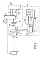
- FIG 3 shows one example of the type of circuitry that can be used for the token and the interrogation station. It will be appreciated that many other types of circuit could alternatively be used.
- the interrogation station 32 has transmission and reception coils 52 and 54, respectively.
- the transmission coil 52 is driven by a drive circuit 56 which is operated in response to a signal derived from a microprocessor 58.
- the microprocessor 58 also receives, via an input circuit 60, and processes signals from the reception coil 54, and delivers signals to the main data bus 62 of the control circuit of the coin handling mechanism.
- the data bus 62, input circuit 60 and drive circuit 56 are connected to the microprocessor 58 via a multiplexing circuit 64 which communicates with the microprocessor 58 via a data bus 66, an address bus 68, and a read/write signal path 70.
- the microprocessor 58 controls the reading of data from, and delivering of data to, the token 50, and also communicates with the main coin mechanism circuitry so as to send the token value to this circuitry and to receive therefrom the remaining value after a transaction or series of transactions has been carried out.
- the main coin mechanism circuitry may be of per se known form, such as that described in published U.K. Patent Specification No. 2,110,862A.
- the main processor of the coin mechanism circuitry could be used to control the interrogation station directly, so that the additional microprocessor 58 would not be required.
- the microprocessor 58 causes the transmitter drive circuit 56 to drive the coil 52.
- the circuit 56 is so arranged that the output frequency used to drive the coil 52 sweeps from a low value to a high value each time the circuit 56 is operated.
- the output frequency is shown in Fig. 4(a).
- the token 50 includes a circuit generally indicated at 72 for selectively absorbing the energy transmitted by the coil 52.
- the circuit 72 is a resonant circuit including a coil 74 and a parallel-connected capacitor 76.
- a further parallel-connected capacitor 78 can be switched in and out of circuit using a semiconductor switch 80 in order to vary the resonance frequency of the circuit 72.
- the energy transmitted by the transmission coil 52 is picked up by the reception coil 54, and the signal from this coil 54 is delivered to a comparator in the input circuit 60 for amplitude-detection purposes.
- the signal generated by the input circuit 60 is shown in Fig. 4(b). It will be noted that each time the frequency of the signal delivered to the transmission coil 52 is swept, there is a point at which the energy is strongly absorbed by the resonant circuit 72, so that a short pulse is produced in the signal generated by the input circuit 60. The precise time, within each frequency sweep, at which this pulse is produced is dependent upon the resonance frequency of 'the circuit 72, and can therefore be altered by operation of the switch 80.
- Transmission of data from the token 50 to the interrogation station 32 is achieved by selective operation of the switch 80, for example such that a data bit "1" is represented by the absorption frequency when the switch is closed, and a data bit "0" is represented by the absorption frequency when the switch is open.
- This data can be detected by the microprocessor 58 in a variety of ways.
- the microprocessor could be arranged to note when the interval between the pulses received from the circuit 60 alters from a value P1 (see Fig. 4(b)), which is determined by the rate at which the drive circuit 56 is operated, to a value P2, which occurs when the resonance frequency has just been altered from its low value to its high value, or to a value P3, which occurs when the resonance frequency has just been altered from its high value to its low value.
- the microprocessor could be arranged so that each time a token is received, the time t1 (see Fig. 4(b)) from the start of the frequency sweep to the time at which the circuit 60 produces a pulse is measured. During future frequency sweeps, the resonance frequency is determined to be low if the time taken for a pulse to be generated is substantially equal to t1, and is determined to be high if the time is a significantly greater value t2.
- Data is transmitted to the token 50 by amplitude- modulating the signal applied to the transmission coil 52.
- the amplitude modulated signal can either have a varying frequency, as in Fig. 4(a), or may simply have a single frequency, for example located at the midpoint of the frequency sweep.
- the signal is picked up by the resonant circuit 72, which has an output connected to a detection circuit 82.
- the circuit 82 is operable to derive from the received waveform the data transmitted by the interrogation station 32.
- the circuit 80 can detect predetermined codes which are transmitted by the station 32. Detection signals indicative of these codes are delivered to a control circuit 84. The detection circuit 82 can also detect data intended for storage in the token 50. This data is delivered to a memory circuit 86.
- the memory circuit 86 is a recirculating shift register, the contents of which are shifted back into the register as they are read out.
- the control circuit 84 can cause data to be read out of the memory circuit 86 and delivered to a transmission circuit 88.
- the control circuit 84 causes the transmission circuit 88 selectively to operate the switch 80 in accordance with the data from the memory circuit 86, so that the data is sent to the interrogation station 32.
- the operation of the circuitry is as follows. When a token has been received in the interrogation station, the drive circuit 56 is operated. This is detected by the token 50, which then sends to the station 32 a predetermined code which represents a request for the interrogation station 32 to transmit a security code which the microprocessor 58 stores.
- This station security code is checked by the control circuit 84, and further operations are permitted only if the station security code is suitable for that token. This procedure, which is optional, is done to ensure that any subsequent alteration of the data in the token only takes place if the machine containing the interrogation station 32 is an appropriate one, for example one owned by a particular company.
- the station security code recognition operation could for example be carried out by determining whether the code matches a number stored in the memory circuit 86; this would enable tokens having the same circuits to be made suitable for different machines simply by altering the contents of the memory circuit 86.
- the token then sends to the interrogation station 32 a token security code stored in the memory circuit 86.
- the microprocessor 58 determines whether this token security code is appropriate for that machine, and only permits subsequent transactions if the code is appropriate. This ensures that the machine cannot be operated by insertion of tokens supplied by unauthorised companies.
- the token security code is transmitted only if the station security code has been found to be appropriate. This improves the security of the system, as it renders it difficult for unauthorised people to determine the token security code.
- the token 50 proceeds to transmit a token value stored in the memory circuit 86. This could, if desired, be carried out only after the interrogation station 32 has first acknowledged that the token security code is appropriate.
- the microprocessor 58 then sends signals to cause the credit count to be incremented by the token value.
- the user is then permitted to carry out transactions in the same manner as if the credit count had been incremented by the insertion of coins.
- the user After the completion of the transaction or series of transactions, the user operates an ESCROW button.
- the device responds to this by delivering to the microprocessor 58 data representing the remaining credit.
- the interrogation station 32 then transmits this data to the token 50.
- the detection circuit 82 recognises a special code which has been added to the transmitted data, and this code causes the control circuit 84 to shift into the memory circuit 86 data from the detection circuit 82 representing the remaining credit. This data replaces the previously-stored token value.
- the token 50 then acknowledges receipt of the data, following which the device causes the retraction of the gate 42 and thus permits the token 50 to be returned to the user.
- Tokens can be used with the device for a number of supplementary purposes. For example, by inserting in the memory circuit 86 of a token a special code in place of or in addition to the token security code, the microprocessor 58 can be caused, upon detecting this code, to enter a special mode. In this mode, the microprocessor 58 extracts from the token 50 data which is then sent to the coin mechanism circuitry to alter a list of prices stored therein. This is a convenient way of handling changes in the price of products vended by the machine.
- the microprocessor 58 can be caused to enter a further mode used to change the security code which the microprocessor 58 stores, so that in future different security codes would be recognised as appropriate for use with that device.
- a convenient way of achieving this latter function would be for the microprocessor to enter the further mode on receiving a first token storing the special code, but to wait for receipt of a second token before actually changing its stored code.
- the security code stored in the microprocessor 58 is replaced by that stored in the token.
- Tokens can also be used for collecting data from the device.
- a further predetermined code is stored in the memory circuit 86, and this is recognised by the microprocessor 58 as an authorisation to transfer into the token 50 the data which is to be collected.
- the token can, upon payment, have its original value re-inserted into its memory circuit 86. This can be accomplished using a machine which is similar in structure-to the interrogation station 32.
- the microprocessor 58 would be arranged to deliver to the token 50 a further predetermined value, which for security purposes would be kept secret.
- This further value would be recognised by the detection circuit 82 and would cause subsequent data to be entered into the memory circuit 86 as the token value.
- the detection circuit 82 is arranged so that increased token values can only be inserted into the memory circuit 86 when this special code has been received, although of course it will permit decreased values to be entered in other circumstances.
- the token 50 is always returned to the user after a transaction or a series of transactions has been carried out.
- a gate is provided for selectively directing tokens from the interrogation station 32 either to the reject tray or to a storage box. Under normal circumstances the token is returned to the user. However, if the token value decreases to zero, in a debit system, or if the stored account number in a credit token is invalid, the token can instead be retained in the storage box inside the machine.
- Interrogation of the token and insertion of data therein is carried out in the above arrangement while the token is held at the interrogation station 32.
- interrogation could take place as the token passes through the coin validator 4.
- interrogation could be carried out using components which are also used for coin validation, e.g. an inductive coil.
- the gate 42 can be arranged to be normally open so that all items other than valid tokens which are rejected by the coin validator 8 are delivered straight to the reject tray.
- FIGs 5 and 6 show a preferred structure of the token 50.
- the token is small, and in fact coin-sized and shaped.
- the token has a lithium battery 100 on which is mounted a printed circuit board 102 via an annular spacer 104.
- the entire circuit of the token 50 with the exception of the coil 74 and the capacitors 76 and 78, is contained within a single integrated circuit chip 106 mounted on the printed circuit 102.
- the capacitors 76 and 78 may be of the ceramic chip type and are also mounted on the printed circuit board 102.
- the coil 74 is formed by a printed circuit etched on the printed circuit board 102.
- the coil has a spiral configuration, and may contain for example about ten turns.
- the token is encapsulated as indicated at 108 in plastics material.
- the token could have an openable casing to allow replacement of the battery 100.
- the token 50 operates correctly irrespective of its specific orientation within the interrogation station 32.
- the input circuit 60 produces a two-level output dependent upon the amplitude of the signal received by the coil 54. This signal is then processed by the microprocessor 58.
- the circuit 60 could contain for example a phase locked loop or a monostable circuit for processing the signal from the coil 54 in order that it may deliver to the microprocessor 58 a digital signal representing the data transmitted by the token 50.
- the arrangement described above involves a token which communicates using inductive techniques, and preferably using a transmission frequency in the region of about 10 MHz to 100 MHz.
- the token handling device 100 comprises a transmitter drive circuit 102 coupled to a transmitting antenna 104.
- the token 106 is, in use, disposed between the transmitting antenna 104 and a receiving antenna 108.
- a receiver circuit 110 is connected to the receiving antenna 108.
- a microprocessor 112 has an output line 114 for controlling the transmitter drive circuit 102, three output lines 116 which control the sensitivity of the receiver circuit 110 as will be described, and an input line 118 for receiving data from the receiver circuit 110.
- the lines 114, 116 and 118 can be connected to the microprocessor 112 via appropriate interface circuitry.
- the microprocessor 112 is also connected to ROM, RAM and non-volatile writable memory circuits 120, 122, and 124, respectively.
- the non-volatile memory circuit 124 is preferably an EAROM.
- the circuitry of the token 106 is shown in Fig. 7.
- the token has an antenna 130 which is connected via a diode 132 to a power storage capacitor 134.
- the energy transmitted by the antenna 104 is half-wave rectified by the diode 132 and stored by the capacitor 134, the voltage across which is used to power the circuitry of the token 106.
- the received carrier is also delivered to a diode 136 which is used for a.m. demodulation purposes. Interruptions in the transmitted carrier result in pulses at the output of diode 136 which are delivered to a Schmitt inverter 138, the output of which is connected to a latch 140.
- the latch 140 can be read and cleared by a microprocessor 142 which has ROM, RAM and non-volatile (preferably EAROM) memory circuits 144, 146 and 148, respectively.
- the data is delivered to the microprocessor on line 150 and a clear pulse is delivered to the latch on line 152.
- the microprocessor 142 has an additional output line 154 which can control an analog switch 156. When the switch is turned on, the terminals of the antenna 130 are shorted via a diode 158.
- the lines 150, 152 and 154 would normally be connected to the microprocessor 142 via appropriate interface circuitry (not shown).
- the token handling device is arranged, upon receipt of a token 106, to cause the transmitting antenna 104 to start transmitting a carrier wave at a frequency of the order of magnitude of 100 kHz. Some of the transmitted energy will be picked up by the antenna 130 in the token 106 and used to power-up the token. Some of the remaining energy will be picked up by the receiving antenna 108.
- the transmitter drive circuit 102 is so controlled as to produce interruptions in the carrier transmission.
- the interruptions are at regular intervals (say every 1 ms), and each lasts for, say, 3 carrier cycles. They are sufficiently short that the voltage stored across the capacitor 134 in the token 106 does not drop to an extent which would result in interference with the operation of the token circuitry.
- the microprocessor 112 in the token handling device then adjusts the sensitivity of the receiver circuitry 110 using the lines 116 until the microprocessor receives on line 118 clearly defined pulses as shown in Fig. 8(a), which correspond to the interruptions in the transmitted carrier.
- Adjusting receiving sensitivity in this way should be sufficient to ensure that shorting of the antenna 130 in the token 106, which results in a change in the amount of absorbed energy, will result in detectable pulses in the output of the receiving antenna 108. If desired, however, the system could be arranged so that receiver sensitivity is adjusted in response to actual operation of the switch 156 in the token 106 to ensure that the resulting pulses are detectable.
- the token handling device starts to communicate with the token.
- alternate pulses 200 in the carrier wave as shown in Fig. 8(a) are used as clock pulses, while the intervening pulses 202 are used as data pulses.
- a data value of zero is signified by an interruption in the carrier and consequently a pulse 202, and a data value of 1 is signified by no interruption of the carrier, which will result in a missing pulse 202.
- the microprocessor 142 repeatedly checks for a pulse in the latch 140, and upon detecting the pulse clears the latch. The period between successive pulses is measured and stored. This measured period allows the microprocessor 142 to calculate a "window" period within which the next pulse is expected.
- Data transmissions to the token are always initiated by data value of 1. Accordingly, the microprocessor 142 detects the first time that a pulse does not appear in the latch 140 within the expected period. At that time, the token is able to determine which of the pulses in the succeeding train are clock pulses 200 and which are data pulses 202.
- Data stored in the token is transmitted to the token handling device using the analog switch 156. This can be closed for a brief period between the carrier interruptions. These brief closures of the switch 156 will result in extra pulses appearing on the line 118 from the receiver circuit 110 due to the consequent increase in the energy absorbed by the token 106.
- the arrangement is such that while the token handling device 100 is expecting to receive data from the token 106, it continually transmits data values of zero. The token will have previously received data from the token handling device, and therefore its operation would have been synchronized with the token handling device. Data transmissions from the token are always initiated with a start bit which is transmitted between a clock pulse 200 and a data pulse 202. The start bit is indicated at 204 in Fig. 8(b).
- any data transmission in one direction could be followed by the same data being transmitted in the opposite direction to ensure a reliable and secure operation.
- the token 106 stores in the memory 148 data such as security codes, token value, etc.
- data such as security codes, token value, etc.
- the token and token handling device communicate with each other to check security codes and thus ensure that each is suitable for use with the other.
- the microprocessor then transmits the token value to the token handling device and at the same time stores in a flag location of the memory 148 an indication that this sequence of operations has been completed.
- the transmission of the carrier is then terminated, so that the token no longer receives power. This is particularly useful in a pay phone installation.
- the carrier is transmitted once more and the token powers-up. Power-up always results in the microprocessor 142 first checking the flag in the memory 148. In this case, it will determine that the preceding operations before power-down were performed to transmit the credit value to the token handling device. Accordingly, the token will now (after the security code checking operation has been carried out) wait for a new token credit value to be transmitted by the token handling device so that it can update its stored credit value.
- the microprocessor 142 resets the flag in the memory 148 so that when the token is subsequently released to the user and at a later time inserted again into a token handling device and powered-up it will behave in an appropriate manner to transmit the token value to the device.
- the data in the token is transmitted by the connecting of a low impedance (the diode 158) across the antenna 130.
- the diode 158 is used to prevent problems due to back EMF generated in the antenna 130, and also to ensure that the voltage switched by the analog switch 156 is no greater than the supply voltage of that switch.
- the alteration of the impedance connected to the antenna 130 could be achieved in some other fashion.
- the alteration of the degree of absorption of the electromagnetic radiation could be achieved without affecting the impedance connected to the antenna 130; for example, a separate coil could be used for this purpose.
- Fig. 6 shows in detail the receiver circuit 110 of the token handling device 100.
- the receiving coil 108 forms part of a tuned circuit which is coupled via an a.m. demodulating diode 160 to the inverting input of an amplifier 162.
- the non-inverting input of the amplifier 162 receives a reference potential derived from the junction between, on the one hand, a resistor 164 connected to one power supply rail, and, on the other hand, a parallel network of resistors 166 connected via respective analog switches 168 to the other power supply rail.
- the analog switches 168 are controlled by the lines 116 from the microprocessor 112.
- the resistors 166 have values R, 2R and 4R. It will be appreciated .that the reference potential delivered to the non-inverting input of the amplifier 162 will vary depending upon which, if any, of the analog switches 168 are closed. This therefore alters receiver sensitivity.
Abstract
Description
- This invention relates to tokens and token handling devices.
- The invention is particularly, although not exclusively, useful in the field of vending machines, gaming machines, amusement machines, pay telephones, change-giving apparatus and like machines which dispense something of value or perform a service or function in exchange for money received from the user. Such machines will for convenience be referred to herein as coin operated machines. These machines generally handle a large volume of coins, which means that the machines need to have a large storage space for the coins, that the coins need to be regularly collected and transported to a central location, and that they then need to be counted and delivered to a bank. This procedure is inconvenient and expensive for the owner of the machine. In addition, the user has to have coins available in order to use the machine, and .would therefore need to carry an inconveniently large number of coins if he wished to use the machine often. He would have to have the correct denominations of coins available unless the machine was of the change-giving type, and in the latter,case carrying the change around would be inconvenient.
- Some of the machines referred to above, for example gaming machines, have been capable of handling special tokens in addition to genuine coins. However these tokens have generally been treated in much the same way as genuine coins.
- The present invention is concerned with arrangements which can substantially mitigate the disadvantages referred to above by arranging for the machines to be able to handle, in place of or preferably in addition to genuine coins, data-storing tokens which can be used to authorise transactions of different values, and which are preferably returned by the machine so that the tokens can be repeatedly used. Two types of system could be used: a debit system in which a user makes an initial payment for a token which stores therein data representing its value, the machine being operable to alter this stored data upon use of the token so as to reduce the value by an amount corresponding to the value of the transaction; and a credit system in which the token stores data representing an account of the user, the machine being operable upon use of the token to note this account data so that the account can then be debited by an amount corresponding to the value of the transaction. In the latter case, the machine could be connected on-line to a central station which keeps the account information, or could store information which is regularly collected by means of data storage modules.
- Allowing the user to operate the machine using a "debit" or "credit" token effectively avoids the problems referred to above relating to the handling and carrying of large numbers of coins.
- It will be appreciated, however, that aspects of the invention have value in other fields. For example, the invention is also useful in the field of identification tags, wherein for example data-storing tokens could be used with automatic equipment for gaining access to areas restricted to authorised personnel.
- A first specific aspect of the invention relates to a device which handles both coins and tokens storing data which can be determined upon communication between the device and the token, the device having a common path for receiving the coins and the tokens and for delivering them to testing apparatus for validating the coins and communicating with the tokens.
- The use of a common path has the advantage that the user can operate the machine using tokens in the same way as the machine is operated using coins, e.g. by inserting tokens and coins through the same slot. This feature also has the substantial advantage that, because it is not necessary to provide a separate entrance slot and path for the tokens, modifying the vast number of existing machines already in use so that they can additionally handle tokens is rendered much more simple.
- The testing apparatus is preferably arranged to have two separate testing stations, one for validating the coins and the other' for communicating with the tokens, the arrangement being such that only those items which are rejected by the first testing station are delivered to the second testing station.
- It is preferred that the coin validator be the first testing station. This permits existing coin operated machines to be adapted to handle tokens without requiring any physical modification to the coin handling mechanism up to and including the coin validator. Instead, it is merely necessary to install the test station for the tokens along the path taken by items rejected by the coin validator. This feature is particularly useful in that it is very common for coin mechanisms incorporating a coin validator and a separator for separating rejected items and genuine coins to form a unit, and for the same type of unit to be installed in different kinds of coin operated machines. In these circumstances, the coin path leading to the validator may vary substantially depending upon the machine in which the coin mechanism is installed. If the token interrogation station were to be installed in front of the coin validator, in some cases there may be insufficient room in the vending machine to permit this modification without substantially changing the configuration of the coin mechanism itself. This is avoided in the preferred embodiment by installing the token testing station within the unit and along the reject path.
- It is envisaged that in most public installations, the majority of items inserted into the device will be genuine coins, and that very few items which are neither genuine coins nor tokens will be inserted. Thus, by arranging for coin validation to occur first, the majority of items delivered to each testing station will be appropriate for that station, so that the device operates in an efficient manner.
- The device preferably has means for temporarily retaining the tokens within the device until a transaction is completed. If the token is a debit token, this feature is desired to enable the value stored in the token to be altered by an amount corresponding to the value of the transaction before being returned to the user. If the token is a credit token, this feature is desirable, particularly in "multi-vend" machines which can be operated a number of times in succession without requiring the user repeatedly to insert coins or tokens, because retrieving the token would be a convenient way of signifying the end of a transaction or a series of transactions. A credit token could instead be returned immediately to the user after interrogation, but this means that the user would then have to perform some operation to advise the machine when his transactions are completed, and if he were to forget to do this the values of subsequent transactions carried out by other users would be deducted from his account.
- The holding station at which the token is temporarily retained is preferably, like the token testing station, disposed after the validator and more preferably after separation by an accept/reject gate so that the station receives only those items which are rejected by the validator. In a particularly convenient embodiment, the token testing station and holding station are combined. This has the advantage that communication with the token can be carried out after the token has been halted at the holding station.
- The device preferably also has means for updating or otherwise altering the data in the token, or introducing new data into the token, which in the debit system would be used to alter the token's value after a transaction has been carried out. The means for accomplishing this is preferably also disposed at the holding station, although in an alternative embodiment it could be disposed downstream of the holding station so as to update the data during the token's exit from the machine.
- Preferably, means for obtaining data from the tokens and means for updating information in the tokens are both disposed at the holding station. The two functions may be performed using common components.
- According to a second specific aspect of the invention, a token storing alterable data which can be determined by communication with the token is substantially coin-shaped and sized. The token is such that it can enter and pass through a standard coin handling mechanism. This has a number of advantages. It means that modifying existing coin operated machines so that they can additionally handle the tokens is rendered much easier, because it merely involves fitting a means for communicating with the token to otherwise fairly standard equipment. For example, as described above, a testing station can be disposed along a reject path of the mechanism, so that the token passes through the validator, is rejected and then reaches the testing station. This aspect of the invention also has the advantage that even if machines are intended to be used only with tokens, and not with genuine coins, it is nevertheless possible to use standard coin handling mechanisms and techniques.
- The token may contain its own power supply, but preferably is powered by energy transmitted by the token handling device.
- The tokens used in the various aspects of the present invention are preferably arranged so that they and the device can communicate in a "contactless" manner. Various techniques can be used. For example, very low frequency radio transmission can be used to obtain data from, and if desired to pass data to, the token. British Patent Specifications Nos. 1,599,120 and 2,077,556A describe radio techniques for interrogation. Other methods, e.g. optical techniques, could alternatively be used.
- One alternative technique, which is considered particularly advantageous, forms the subject of a third aspect of the present invention. In accordance with this aspect, a token handling device, referred to also as a token interrogator, has means for communicating with a token by determining how an electromagnetic field is absorbed by the token. The invention also extends to a token suitable for use with such a device. The token preferably has a field-absorbing circuit which can be controlled so as to alter the degree or nature of the absorption.
- In one embodiment described herein, this is a resonant circuit whose resonant frequency can be switched between at least two values. The device may communicate with the token by generating an electromagnetic field of different frequencies, and more preferably of a continuously-swept frequency. The device determines data stored in the token in accordance with the frequencies at which absorption of the field occurs. Preferably, the device determines the data in response to changes in the absorption frequency, so that it operates substantially independently of the specific resonance frequencies of the resonant circuit.
- An alternative, preferred arrangement is also described herein. In this arrangement, the token is powered by an electromagnetic signal transmitted by the interrogator (preferably of a frequency around 100 kHz). The same signal as is used for transmitting power is also used for communication between the token and the interrogator. Data is communicated to the token by selectively interrupting the power transmissions for brief periods. The token has power storing means so that these interruptions do not interfere with its operation. The token sends data to the interrogator by selectively coupling a low impedance across its receiving antenna. This alters the degree of energy absorption, which can be sensed by the interrogator. The data transmissions are preferably made at predetermined times, and to facilitate this a clock signal is preferably used. Preferably, the interrogator transmits clock pulses in the same way as data pulses, and these clock pulses are used both for transmissions to the token and transmissions from the token.
- In addition, in this arrangement, the token contains a non-volatile readable and writable memory (preferably an EAROM). This is desirably used for storing operational data such as the token value, but also has another use. In particular, it may be desirable in many circumstances to terminate the power transmission to the token before all the operations involving the token have been completed. This for example may be useful for reducing power consumption when the token is used in a pay phone installation; the token may be interrogated when first inserted to check its validity, whereupon the power is cut off for the duration of the telephone call and thereafter reapplied to allow the token value to be reduced by an amount corresponding to the cost of the telephone call. Thus, on powering-up of the token, either of two sequences of operations of the token could be required (i.e. transmission of data to the interrogator, or receipt of data from the interrogator). The non-volatile memory in the token can be used to store a flag which indicates which part of the complete cycle of operations the token is in, and which is used to determine what actions are taken by the token upon powering-up.
- This arrangement embodies a number of further independently inventive aspects, amongst which are:
- a) A system comprising a token which receives power from an antenna and sends data by altering the impedance across the antenna (preferably by shorting-out or at least connecting a very low impedance across the antenna).
- b) A token and interrogator between which two- way communication can be established using the same carrier signal, which signal originates from the interrogator (and preferably transmits power and/or clock pulses to the token).
- c) A token and interrogator between which two- way communication can be established, communication in both directions being synchronized with clock pulses transmitted by the interrogator.
- d) A system comprising a token powered by energy received from the interrogator, the token having a non-volatile writable memory and being arranged to perform, following power-up, one of a plurality of sequences of operations dependent upon flag data stored in the memory, at least one of those sequences resulting in a change in that flag data.
- It will be appreciated that these aspects of the invention reside in the token and interrogator individually, as well as the combination thereof.
- The token handling device may have transmission and reception coils for transmitting and receiving the signal which is selectively absorbed by the token. Alternatively, a single coil could be used for both these purposes.
- In accordance with a still further aspect of the invention a token handling device is arranged for automatically altering its sensitivity to received transmissions in the presence of a token, and preferably each time a new token is received by the handling device. The transmission carrier could originate at the token, but this aspect is particularly useful-when the token transmits data by altering the degree by which it absorbs a carrier transmitted from a different source, and also when the token is powered by received electromagnetic energy, because in those circumstances the signals received by the token handling device may vary due to slight differences in the tokens, or slightly different positions of the tokens. This can be compensated for by adapting the receiver sensitivity to ensure that changes in absorption of the carrier transmitted by the token handling device are correctly received by the token handling device.
- The device is preferably able to communicate with the token irrespective of the particular orientation of the token.
- According to a further specific aspect of the invention, there is provided a token handling device which performs operations in accordance with operational data stored in the device, and which is capable of communicating with a token in order to determine token data stored thereby, the device being operable to enter a first mode or a second mode in dependence upon the token data, the device being operable in the first mode to perform a said operation, and in the second mode to alter the operational data in a manner dependent.upon said token data.
- It is envisaged that the device would normally be caused by entered tokens to perform operations (such as permitting access to certain areas, or in the case of vending machines and the like vending a product or performing a service), but could also have its operational parameters altered by entering a special token storing predetermined data. This would be useful for example if a vending machine owner wished to change the pricing data stored in his vending machines. He would have a specially encoded token which would cause this to occur upon insertion into the vending machine, so that the pricing change could be achieved as easily, and using the same electronic components, as when using a token to purchase a product from the machine.
- In the field of identification tokens, which may store a special code which when read out by the device permits access to a particular area, it may be desired for security reasons to change the code which authorises access. This could be achieved very easily by using a specially encoded token which stores data such as to cause the device to enter the second mode, in which information in the token is used to change a stored parameter so that in future the device will recognise a different security code as being appropriate for authorising access.
- According to another specific aspect of the invention, there is provided a token handling device operable to receive and communicate with tokens in order to determine data stored thereby, and operable to perform a transaction and to alter the data stored by the token in accordance with a predetermined value associated with the transaction, the device being operable before performing the transaction to carry out a security code recognition operation to determine whether the token stores a security code which is appropriate to that machine, and to carry out the transaction' only if the token stores such an appropriate security code.
- Thus, vending machines, and like machines for dispensing products or performing services, can be designed so that they will accept tokens issued by a particular company, for example that owning the vending machines, but will not accept tokens issued by other companies, which tokens may be identical except for the security code stored therein. In this way, an owner of a chain of vending machines can ensure that he is paid for all the tokens used to obtain products from his machines.
- Preferably, the token handling device itself must store a security code which is appropriate for the token in order for transactions to be carried out. In this way, it can be ensured that a company's tokens will not have their values altered in an unauthorised manner by insertion into another company's token handling device.
- The token handling device may be arranged additionally to handle genuine coins.
- In a preferred embodiment of the invention, aspects described above are combined to produce a token handling system of substantial advantage and utility.
- Arrangements embodying the invention will now be described by way of example with reference to the accompanying drawings, in which:
- Figure 1 is a schematic view of a coin and token handling device according to the present invention;
- Figure 2 shows a token in a testing station of the device of Figure 1;
- Figure 3 is a schematic block diagram of the circuitry of the token and the testing station in a first arrangement;
- Figs. 4(a) and (b) are waveform diagrams for illustrating the operation of the circuitry of Fig. 3;
- Fig. 5 is a block diagram showing the token handling device and token in a second arrangement;
- Fig. 6 is a circuit diagram of a receiver of the token handling device of Fig. 5;
- Fig. 7 is a diagram of the circuitry of the token of Fig. 5; and
- Fig. 8 shows waveforms of signals received by the receiver of the token handling device of Fig. 5.
- Referring to Figure 1, the coin and
token handling apparatus 2 includes acoin validator 4 for receiving coins and tokens as indicated at 6 travelling along a common path 7 from an entrance slot (not shown). During the passage of the coins and tokens 6 along apath 8 in thevalidator 4, test operations are carried out to determine whether a valid coin has been inserted, and if so the denomination of the coin. These tests are standard ones, and may for example be inductive tests. - Acceptable coins then enter a
coin separator 10, which has a number of gates (not shown) controlled by the circuitry of the device for selectively diverting the coins from amain path 12 into any of a number offurther paths path 12 to apath 20 leading to a cashbox. If the item tested in thevalidator 4 is not determined to be an acceptable coin, it is delivered to areject path 30 instead of continuing through theseparator 10. - Each of the
paths coin containers - Whenever a validator recognises an acceptable coin, a credit count is incremented by an amount corresponding to the value of the coin. When sufficient credit has been accumulated, the
device 2 produces a signal indicative of this. For example, in a preferred embodiment thedevice 2 is installed in a vending machine (not shown), and the signal will indicate to the vending apparatus that a user may initiate the vending of a product. The apparatus may be arranged to operate such that products can be repeatedly vended until the credit count drops to a level below the lowest of the prices of the products which the machine vends. - At any stage, the user may operate an "ESCROW" button, which terminates the transaction or series of transactions, and initiates the delivery of change of a value corresponding to the remainder of the accumulated credit, which credit is then cleared.
- The arrangement described so far is quite conventional, and the details of particular structures suitable for accomplishing these functions will therefore not be described.
- The device of Figure 1 has, in addition to these . structures, a token testing or
interrogation station 32, shown in more detail in Figure 2. Thisstation 32 is situated along thereject path 30 so that all rejected items are delivered to thestation 32 before being delivered to a reject tray for retrieval by the user. - Referring to Figure 2, the
reject path 30 extends between arear wall 34, a front wall which is not shown in Figure 2 to permit the interior of the interrogation station to be seen, and sidewalls 36 and 38. Therear wall 34 has anaperture 40 so that agate 42 can be selectively thrust into and withdrawn from thepath 30 by a solenoid 44. - Normally, the
gate 42 is located in thepath 30 so that all rejected items are stopped at theinterrogation station 32. Each item is interrogated, and if it is found not to be a token, thegate 42 is withdrawn so that the item can proceed to the reject tray. - If the item is a token, it is held by the
gate 42 at theinterrogation station 32 until the completion of the transaction or series of transactions carried out by the user, following which thegate 42 is withdrawn so that the token is returned to the user. - Figure 2 shows a
token 50 of a preferred embodiment of the invention, which is for use with debit systems and which therefore stores data representing a particular value, which value is decremented after a transaction or a series of transactions has been carried out and before the token 50 is returned to the user. - Figure 3 shows one example of the type of circuitry that can be used for the token and the interrogation station. It will be appreciated that many other types of circuit could alternatively be used.
- The
interrogation station 32 has transmission and reception coils 52 and 54, respectively. Thetransmission coil 52 is driven by adrive circuit 56 which is operated in response to a signal derived from amicroprocessor 58. Themicroprocessor 58 also receives, via an input circuit 60, and processes signals from thereception coil 54, and delivers signals to themain data bus 62 of the control circuit of the coin handling mechanism. Thedata bus 62, input circuit 60 and drivecircuit 56 are connected to themicroprocessor 58 via a multiplexing circuit 64 which communicates with themicroprocessor 58 via a data bus 66, anaddress bus 68, and a read/write signal path 70. Themicroprocessor 58 controls the reading of data from, and delivering of data to, the token 50, and also communicates with the main coin mechanism circuitry so as to send the token value to this circuitry and to receive therefrom the remaining value after a transaction or series of transactions has been carried out. The main coin mechanism circuitry may be of per se known form, such as that described in published U.K. Patent Specification No. 2,110,862A. In an alternative arrangement, the main processor of the coin mechanism circuitry could be used to control the interrogation station directly, so that theadditional microprocessor 58 would not be required. - In order to interrogate the token 50, the
microprocessor 58 causes thetransmitter drive circuit 56 to drive thecoil 52. Thecircuit 56 is so arranged that the output frequency used to drive thecoil 52 sweeps from a low value to a high value each time thecircuit 56 is operated. The output frequency is shown in Fig. 4(a). - The token 50 includes a circuit generally indicated at 72 for selectively absorbing the energy transmitted by the
coil 52. In this particular case, thecircuit 72 is a resonant circuit including acoil 74 and a parallel-connected capacitor 76. A further parallel-connected capacitor 78 can be switched in and out of circuit using asemiconductor switch 80 in order to vary the resonance frequency of thecircuit 72. - The energy transmitted by the
transmission coil 52 is picked up by thereception coil 54, and the signal from thiscoil 54 is delivered to a comparator in the input circuit 60 for amplitude-detection purposes. The signal generated by the input circuit 60 is shown in Fig. 4(b). It will be noted that each time the frequency of the signal delivered to thetransmission coil 52 is swept, there is a point at which the energy is strongly absorbed by theresonant circuit 72, so that a short pulse is produced in the signal generated by the input circuit 60. The precise time, within each frequency sweep, at which this pulse is produced is dependent upon the resonance frequency of 'thecircuit 72, and can therefore be altered by operation of theswitch 80. - Transmission of data from the token 50 to the
interrogation station 32 is achieved by selective operation of theswitch 80, for example such that a data bit "1" is represented by the absorption frequency when the switch is closed, and a data bit "0" is represented by the absorption frequency when the switch is open. - This data can be detected by the
microprocessor 58 in a variety of ways. For example, the microprocessor could be arranged to note when the interval between the pulses received from the circuit 60 alters from a value P1 (see Fig. 4(b)), which is determined by the rate at which thedrive circuit 56 is operated, to a value P2, which occurs when the resonance frequency has just been altered from its low value to its high value, or to a value P3, which occurs when the resonance frequency has just been altered from its high value to its low value. - Alternatively, the microprocessor could be arranged so that each time a token is received, the time t1 (see Fig. 4(b)) from the start of the frequency sweep to the time at which the circuit 60 produces a pulse is measured. During future frequency sweeps, the resonance frequency is determined to be low if the time taken for a pulse to be generated is substantially equal to t1, and is determined to be high if the time is a significantly greater value t2.
- Neither of these methods relies upon the resonance frequency having specific values, so that large tolerances are permitted in the token circuitry.
- Data is transmitted to the token 50 by amplitude- modulating the signal applied to the
transmission coil 52. The amplitude modulated signal can either have a varying frequency, as in Fig. 4(a), or may simply have a single frequency, for example located at the midpoint of the frequency sweep. - The signal is picked up by the
resonant circuit 72, which has an output connected to a detection circuit 82. The circuit 82 is operable to derive from the received waveform the data transmitted by theinterrogation station 32. - The
circuit 80 can detect predetermined codes which are transmitted by thestation 32. Detection signals indicative of these codes are delivered to acontrol circuit 84. The detection circuit 82 can also detect data intended for storage in the token 50. This data is delivered to amemory circuit 86. - In the present embodiment, the
memory circuit 86 is a recirculating shift register, the contents of which are shifted back into the register as they are read out. - The
control circuit 84 can cause data to be read out of thememory circuit 86 and delivered to atransmission circuit 88. Thecontrol circuit 84 causes thetransmission circuit 88 selectively to operate theswitch 80 in accordance with the data from thememory circuit 86, so that the data is sent to theinterrogation station 32. - The operation of the circuitry is as follows. When a token has been received in the interrogation station, the
drive circuit 56 is operated. This is detected by the token 50, which then sends to the station 32 a predetermined code which represents a request for theinterrogation station 32 to transmit a security code which themicroprocessor 58 stores. - This station security code is checked by the
control circuit 84, and further operations are permitted only if the station security code is suitable for that token. This procedure, which is optional, is done to ensure that any subsequent alteration of the data in the token only takes place if the machine containing theinterrogation station 32 is an appropriate one, for example one owned by a particular company. The station security code recognition operation could for example be carried out by determining whether the code matches a number stored in thememory circuit 86; this would enable tokens having the same circuits to be made suitable for different machines simply by altering the contents of thememory circuit 86. - Assuming that the station security code is appropriate for that token, the token then sends to the interrogation station 32 a token security code stored in the
memory circuit 86. Themicroprocessor 58 determines whether this token security code is appropriate for that machine, and only permits subsequent transactions if the code is appropriate. This ensures that the machine cannot be operated by insertion of tokens supplied by unauthorised companies. - It will be noted that the token security code is transmitted only if the station security code has been found to be appropriate. This improves the security of the system, as it renders it difficult for unauthorised people to determine the token security code.
- After the security code recognition operations, the token 50 proceeds to transmit a token value stored in the
memory circuit 86. This could, if desired, be carried out only after theinterrogation station 32 has first acknowledged that the token security code is appropriate. - The
microprocessor 58 then sends signals to cause the credit count to be incremented by the token value. The user is then permitted to carry out transactions in the same manner as if the credit count had been incremented by the insertion of coins. - After the completion of the transaction or series of transactions, the user operates an ESCROW button. The device responds to this by delivering to the
microprocessor 58 data representing the remaining credit. Theinterrogation station 32 then transmits this data to the token 50. The detection circuit 82 recognises a special code which has been added to the transmitted data, and this code causes thecontrol circuit 84 to shift into thememory circuit 86 data from the detection circuit 82 representing the remaining credit. This data replaces the previously-stored token value. The token 50 then acknowledges receipt of the data, following which the device causes the retraction of thegate 42 and thus permits the token 50 to be returned to the user. - Tokens can be used with the device for a number of supplementary purposes. For example, by inserting in the
memory circuit 86 of a token a special code in place of or in addition to the token security code, themicroprocessor 58 can be caused, upon detecting this code, to enter a special mode. In this mode, themicroprocessor 58 extracts from the token 50 data which is then sent to the coin mechanism circuitry to alter a list of prices stored therein. This is a convenient way of handling changes in the price of products vended by the machine. - In a similar fashion, the
microprocessor 58 can be caused to enter a further mode used to change the security code which themicroprocessor 58 stores, so that in future different security codes would be recognised as appropriate for use with that device. A convenient way of achieving this latter function would be for the microprocessor to enter the further mode on receiving a first token storing the special code, but to wait for receipt of a second token before actually changing its stored code. On receiving the second token, the security code stored in themicroprocessor 58 is replaced by that stored in the token. This arrangement has particular value when first installing machines, because it allows all machines to be initialised by using the same token, following which each machine will be adapted for use with a particular company's tokens in response to receiving one of those tokens. - Tokens can also be used for collecting data from the device. In this case a further predetermined code is stored in the
memory circuit 86, and this is recognised by themicroprocessor 58 as an authorisation to transfer into the token 50 the data which is to be collected. This could for example be audit data relating to operations which have been carried out by the machine in which the device is installed. Once the value of adebit token 50 has been reduced to zero, the token can, upon payment, have its original value re-inserted into itsmemory circuit 86. This can be accomplished using a machine which is similar in structure-to theinterrogation station 32. In this case, however, themicroprocessor 58 would be arranged to deliver to the token 50 a further predetermined value, which for security purposes would be kept secret. This further value would be recognised by the detection circuit 82 and would cause subsequent data to be entered into thememory circuit 86 as the token value. The detection circuit 82 is arranged so that increased token values can only be inserted into thememory circuit 86 when this special code has been received, although of course it will permit decreased values to be entered in other circumstances. - In the arrangement described above, the token 50 is always returned to the user after a transaction or a series of transactions has been carried out. In an alternative embodiment, a gate is provided for selectively directing tokens from the
interrogation station 32 either to the reject tray or to a storage box. Under normal circumstances the token is returned to the user. However, if the token value decreases to zero, in a debit system, or if the stored account number in a credit token is invalid, the token can instead be retained in the storage box inside the machine. - Interrogation of the token and insertion of data therein is carried out in the above arrangement while the token is held at the
interrogation station 32. Alternatively, interrogation could take place as the token passes through thecoin validator 4. Indeed, interrogation could be carried out using components which are also used for coin validation, e.g. an inductive coil. In this case, thegate 42 can be arranged to be normally open so that all items other than valid tokens which are rejected by thecoin validator 8 are delivered straight to the reject tray. - Figures 5 and 6 show a preferred structure of the token 50. The token is small, and in fact coin-sized and shaped. The token has a
lithium battery 100 on which is mounted a printedcircuit board 102 via anannular spacer 104. The entire circuit of the token 50, with the exception of thecoil 74 and the capacitors 76 and 78, is contained within a singleintegrated circuit chip 106 mounted on the printedcircuit 102. The capacitors 76 and 78 may be of the ceramic chip type and are also mounted on the printedcircuit board 102. - The
coil 74 is formed by a printed circuit etched on the printedcircuit board 102. The coil has a spiral configuration, and may contain for example about ten turns. - The token is encapsulated as indicated at 108 in plastics material. Alternatively, the token could have an openable casing to allow replacement of the
battery 100. - It will be noted that the token 50 operates correctly irrespective of its specific orientation within the
interrogation station 32. - In the above embodiment, the input circuit 60 produces a two-level output dependent upon the amplitude of the signal received by the
coil 54. This signal is then processed by themicroprocessor 58. In an alternative embodiment, the circuit 60 could contain for example a phase locked loop or a monostable circuit for processing the signal from thecoil 54 in order that it may deliver to the microprocessor 58 a digital signal representing the data transmitted by the token 50. - The arrangement described above involves a token which communicates using inductive techniques, and preferably using a transmission frequency in the region of about 10 MHz to 100 MHz.
- It will of course be appreciated that other techniques could be used without requiring major modification of the circuitry. Low frequency radio techniques could be used, or alternatively optical communication techniques.
- Figs. 5 to 8 illustrate a modified version of the circuitry described above in connection with Figs. 3 and 4. Although these will be described as separate embodiments, it will of course be appreciated that individual features described in connection with Figs. 3 and 4 can be used in the embodiment of Figs. 5 to 8, and vice versa. Referring to Fig. 5, the
token handling device 100 comprises atransmitter drive circuit 102 coupled to a transmittingantenna 104. The token 106 is, in use, disposed between the transmittingantenna 104 and a receivingantenna 108. Areceiver circuit 110 is connected to the receivingantenna 108. - A
microprocessor 112 has anoutput line 114 for controlling thetransmitter drive circuit 102, threeoutput lines 116 which control the sensitivity of thereceiver circuit 110 as will be described, and aninput line 118 for receiving data from thereceiver circuit 110. Thelines microprocessor 112 via appropriate interface circuitry. Themicroprocessor 112 is also connected to ROM, RAM and non-volatilewritable memory circuits non-volatile memory circuit 124 is preferably an EAROM. - The circuitry of the token 106 is shown in Fig. 7. The token has an
antenna 130 which is connected via adiode 132 to a power storage capacitor 134. The energy transmitted by theantenna 104 is half-wave rectified by thediode 132 and stored by the capacitor 134, the voltage across which is used to power the circuitry of the token 106. The received carrier is also delivered to adiode 136 which is used for a.m. demodulation purposes. Interruptions in the transmitted carrier result in pulses at the output ofdiode 136 which are delivered to aSchmitt inverter 138, the output of which is connected to alatch 140. Thelatch 140 can be read and cleared by amicroprocessor 142 which has ROM, RAM and non-volatile (preferably EAROM)memory circuits line 150 and a clear pulse is delivered to the latch online 152. - The
microprocessor 142 has anadditional output line 154 which can control ananalog switch 156. When the switch is turned on, the terminals of theantenna 130 are shorted via a diode 158. - The
lines microprocessor 142 via appropriate interface circuitry (not shown). - In use of this embodiment, the token handling device is arranged, upon receipt of a token 106, to cause the transmitting
antenna 104 to start transmitting a carrier wave at a frequency of the order of magnitude of 100 kHz. Some of the transmitted energy will be picked up by theantenna 130 in the token 106 and used to power-up the token. Some of the remaining energy will be picked up by the receivingantenna 108. - The
transmitter drive circuit 102 is so controlled as to produce interruptions in the carrier transmission. The interruptions are at regular intervals (say every 1 ms), and each lasts for, say, 3 carrier cycles. They are sufficiently short that the voltage stored across the capacitor 134 in the token 106 does not drop to an extent which would result in interference with the operation of the token circuitry. - The
microprocessor 112 in the token handling device then adjusts the sensitivity of thereceiver circuitry 110 using thelines 116 until the microprocessor receives online 118 clearly defined pulses as shown in Fig. 8(a), which correspond to the interruptions in the transmitted carrier. - Adjusting receiving sensitivity in this way should be sufficient to ensure that shorting of the
antenna 130 in the token 106, which results in a change in the amount of absorbed energy, will result in detectable pulses in the output of the receivingantenna 108. If desired, however, the system could be arranged so that receiver sensitivity is adjusted in response to actual operation of theswitch 156 in the token 106 to ensure that the resulting pulses are detectable. - Once the receiver sensitivity has been adjusted, the token handling device starts to communicate with the token. To do this,
alternate pulses 200 in the carrier wave as shown in Fig. 8(a) are used as clock pulses, while the interveningpulses 202 are used as data pulses. A data value of zero is signified by an interruption in the carrier and consequently apulse 202, and a data value of 1 is signified by no interruption of the carrier, which will result in a missingpulse 202. - In the token 106, the
microprocessor 142 repeatedly checks for a pulse in thelatch 140, and upon detecting the pulse clears the latch. The period between successive pulses is measured and stored. This measured period allows themicroprocessor 142 to calculate a "window" period within which the next pulse is expected. - Data transmissions to the token are always initiated by data value of 1. Accordingly, the
microprocessor 142 detects the first time that a pulse does not appear in thelatch 140 within the expected period. At that time, the token is able to determine which of the pulses in the succeeding train areclock pulses 200 and which aredata pulses 202. - The above description outlines how data is transmitted to the token.
- Data stored in the token is transmitted to the token handling device using the
analog switch 156. This can be closed for a brief period between the carrier interruptions. These brief closures of theswitch 156 will result in extra pulses appearing on theline 118 from thereceiver circuit 110 due to the consequent increase in the energy absorbed by thetoken 106. - The arrangement is such that while the
token handling device 100 is expecting to receive data from the token 106, it continually transmits data values of zero. The token will have previously received data from the token handling device, and therefore its operation would have been synchronized with the token handling device. Data transmissions from the token are always initiated with a start bit which is transmitted between aclock pulse 200 and adata pulse 202. The start bit is indicated at 204 in Fig. 8(b). - Further data is transmitted bit by bit in succeeding intervals between
clock pulses 200 anddata pulses 202, so that in these intervals anadditional pulse 206 may or may not appear depending upon the data content. - In use of the system, for reliability, any data transmission in one direction could be followed by the same data being transmitted in the opposite direction to ensure a reliable and secure operation.
- The token 106 stores in the
memory 148 data such as security codes, token value, etc. When the token is first received by the token handling device and powered-up by the received energy, the token and token handling device communicate with each other to check security codes and thus ensure that each is suitable for use with the other. Following this operation, the microprocessor then transmits the token value to the token handling device and at the same time stores in a flag location of thememory 148 an indication that this sequence of operations has been completed. - The transmission of the carrier is then terminated, so that the token no longer receives power. This is particularly useful in a pay phone installation. At a subsequent stage when further communication with the token is required, the carrier is transmitted once more and the token powers-up. Power-up always results in the
microprocessor 142 first checking the flag in thememory 148. In this case, it will determine that the preceding operations before power-down were performed to transmit the credit value to the token handling device. Accordingly, the token will now (after the security code checking operation has been carried out) wait for a new token credit value to be transmitted by the token handling device so that it can update its stored credit value. - At the end of this procedure, the
microprocessor 142 resets the flag in thememory 148 so that when the token is subsequently released to the user and at a later time inserted again into a token handling device and powered-up it will behave in an appropriate manner to transmit the token value to the device. - In the above arrangement, it will be noted that the data in the token is transmitted by the connecting of a low impedance (the diode 158) across the
antenna 130. The diode 158 is used to prevent problems due to back EMF generated in theantenna 130, and also to ensure that the voltage switched by theanalog switch 156 is no greater than the supply voltage of that switch. It should be noted though that the alteration of the impedance connected to theantenna 130 could be achieved in some other fashion. In addition, the alteration of the degree of absorption of the electromagnetic radiation could be achieved without affecting the impedance connected to theantenna 130; for example, a separate coil could be used for this purpose. - Fig. 6 shows in detail the
receiver circuit 110 of thetoken handling device 100. The receivingcoil 108 forms part of a tuned circuit which is coupled via ana.m. demodulating diode 160 to the inverting input of anamplifier 162. The non-inverting input of theamplifier 162 receives a reference potential derived from the junction between, on the one hand, aresistor 164 connected to one power supply rail, and, on the other hand, a parallel network ofresistors 166 connected via respective analog switches 168 to the other power supply rail. The analog switches 168 are controlled by thelines 116 from themicroprocessor 112. - The
resistors 166 have values R, 2R and 4R. It will be appreciated .that the reference potential delivered to the non-inverting input of theamplifier 162 will vary depending upon which, if any, of the analog switches 168 are closed. This therefore alters receiver sensitivity.
Claims (12)
Priority Applications (1)
| Application Number | Priority Date | Filing Date | Title |
|---|---|---|---|
| AT84308445T ATE77502T1 (en) | 1983-12-06 | 1984-12-05 | MARKS AND DEVICE FOR MARK PROCESSING. |
Applications Claiming Priority (4)
| Application Number | Priority Date | Filing Date | Title |
|---|---|---|---|
| GB838332443A GB8332443D0 (en) | 1983-12-06 | 1983-12-06 | Tokens and handling devices |
| GB8332443 | 1983-12-06 | ||
| GB08425079A GB2153128B (en) | 1983-12-06 | 1984-10-04 | Token handling device |
| GB8425079 | 1984-10-04 |
Related Child Applications (1)
| Application Number | Title | Priority Date | Filing Date |
|---|---|---|---|
| EP19910201990 Division-Into EP0455315A3 (en) | 1983-12-06 | 1984-12-05 | Tokens and token handling devices |
Publications (3)
| Publication Number | Publication Date |
|---|---|
| EP0147099A2 true EP0147099A2 (en) | 1985-07-03 |
| EP0147099A3 EP0147099A3 (en) | 1986-10-08 |
| EP0147099B1 EP0147099B1 (en) | 1992-06-17 |
Family
ID=26287076
Family Applications (2)
| Application Number | Title | Priority Date | Filing Date |
|---|---|---|---|
| EP19910201990 Withdrawn EP0455315A3 (en) | 1983-12-06 | 1984-12-05 | Tokens and token handling devices |
| EP84308445A Expired - Lifetime EP0147099B1 (en) | 1983-12-06 | 1984-12-05 | Tokens and token handling devices |
Family Applications Before (1)
| Application Number | Title | Priority Date | Filing Date |
|---|---|---|---|
| EP19910201990 Withdrawn EP0455315A3 (en) | 1983-12-06 | 1984-12-05 | Tokens and token handling devices |
Country Status (11)
| Country | Link |
|---|---|
| US (2) | US4674618A (en) |
| EP (2) | EP0455315A3 (en) |
| JP (2) | JPH04211891A (en) |
| KR (1) | KR930004089B1 (en) |
| AU (1) | AU581196B2 (en) |
| BR (1) | BR8406225A (en) |
| CA (1) | CA1240056A (en) |
| DE (1) | DE3485776T2 (en) |
| ES (1) | ES8607594A1 (en) |
| HK (1) | HK19693A (en) |
| MX (1) | MX162845B (en) |
Cited By (32)
| Publication number | Priority date | Publication date | Assignee | Title |
|---|---|---|---|---|
| EP0232174A1 (en) * | 1986-02-07 | 1987-08-12 | Mars Incorporated | Tokens and apparatus for handling tokens |
| WO1988002897A1 (en) * | 1986-10-20 | 1988-04-21 | Mars Incorporated | Oscillators and processor circuits |
| EP0267009A1 (en) * | 1986-11-03 | 1988-05-11 | Mars Incorporated | Data-storing devices |
| WO1989001208A1 (en) * | 1987-08-04 | 1989-02-09 | Mars Incorporated | Data carrying devices |
| WO1989002140A1 (en) * | 1987-08-28 | 1989-03-09 | Mars Incorporated | Data carrying devices |
| WO1990008368A1 (en) * | 1989-01-13 | 1990-07-26 | Coin Controls Limited | Optically coded token and detection system |
| EP0391559A2 (en) * | 1989-04-01 | 1990-10-10 | Gec Avery Limited | Transaction system |
| EP0436497A2 (en) * | 1990-01-05 | 1991-07-10 | Trend Plastics, Inc. | Gaming chip with implanted programmable identifier means and process for fabricating same |
| EP0461878A2 (en) * | 1990-06-14 | 1991-12-18 | Mitsubishi Denki Kabushiki Kaisha | Non-contact IC card and signal processing method thereof |
| EP0525642A2 (en) * | 1991-07-23 | 1993-02-03 | Hitachi Maxell Ltd. | Low-power consumption system configuration for non-contact IC card communication |
| EP0542229A1 (en) * | 1991-11-12 | 1993-05-19 | Dai Nippon Printing Co., Ltd. | Data transfer method for use in semiconductor data recording medium |
| US5398326A (en) * | 1989-05-15 | 1995-03-14 | Dallas Semiconductor Corporation | Method for data communication |
| US5418353A (en) * | 1991-07-23 | 1995-05-23 | Hitachi Maxell, Ltd. | Non-contact, electromagnetically coupled transmission and receiving system for IC cards |
| US5469727A (en) * | 1992-03-06 | 1995-11-28 | Aug.Winkhaus Gmbh & Co. Kg | Electronic lock cylinder |
| US5473145A (en) * | 1992-10-22 | 1995-12-05 | Skidata Computer Gesellschaft M.B.H. | Data carrier |
| US5517015A (en) * | 1990-11-19 | 1996-05-14 | Dallas Semiconductor Corporation | Communication module |
| FR2727548A1 (en) * | 1994-11-29 | 1996-05-31 | Dominique Boiron | Authentication station for tokens of type used in casino for gaming |
| WO1996017329A2 (en) * | 1994-11-29 | 1996-06-06 | Etablissements Bourgogne Et Grasset | Gambling chip authentication device |
| US5552999A (en) * | 1991-07-09 | 1996-09-03 | Dallas Semiconductor Corp | Digital histogram generator systems and methods |
| US5615130A (en) * | 1994-12-14 | 1997-03-25 | Dallas Semiconductor Corp. | Systems and methods to gather, store and transfer information from electro/mechanical tools and instruments |
| FR2739708A1 (en) * | 1995-10-09 | 1997-04-11 | Bourgogne Grasset | Authentication station for tokens of type used in casino for gaming |
| US5652539A (en) * | 1993-02-05 | 1997-07-29 | Dallas Semiconductor Corporation | Power regulator |
| EP0786747A1 (en) * | 1996-01-29 | 1997-07-30 | France Telecom | Virtual IC-card for payments |
| AU681101B2 (en) * | 1993-02-20 | 1997-08-21 | Scheidt & Bachmann Gmbh | Parking card for the charge-related actuation of a parking barrier |
| FR2754620A1 (en) * | 1996-10-10 | 1998-04-17 | Trinh Trang Tan | Data transfer system for payment of road tolls or parking fees |
| EP0613103B1 (en) * | 1993-02-20 | 1998-04-22 | PARKAUTOMATIC HANS FARMONT GmbH | Method for determining parking times and/or fees using parking cards |
| DE19726449A1 (en) * | 1997-06-21 | 1999-01-07 | Nat Rejectors Gmbh | Method and circuit arrangement for checking coins |
| US5895321A (en) * | 1995-10-09 | 1999-04-20 | Etablissements Bourgogne Et Grasset | Gambling chip |
| US6581747B1 (en) | 2000-02-15 | 2003-06-24 | Etablissements Bourgogne Et Grasset | Token with an electronic chip and methods for manufacturing the same |
| US7883408B2 (en) | 2003-05-12 | 2011-02-08 | Gaming Partners International | Station for reading and/or writing in electronic gaming chips |
| US7918455B2 (en) | 2005-11-09 | 2011-04-05 | Gaming Partners International | Chip with insert including an electronic microchip |
| US9731208B2 (en) | 2005-09-12 | 2017-08-15 | Mattel, Inc. | Methods of playing video games |
Families Citing this family (146)
| Publication number | Priority date | Publication date | Assignee | Title |
|---|---|---|---|---|
| ES8607594A1 (en) * | 1983-12-06 | 1986-05-16 | Mars Inc | Tokens and token handling devices. |
| US5359645A (en) * | 1985-07-10 | 1994-10-25 | First Data Corporation Inc. | Voice-data telephonic interface control system |
| US6678360B1 (en) | 1985-07-10 | 2004-01-13 | Ronald A. Katz Technology Licensing, L.P. | Telephonic-interface statistical analysis system |
| US5898762A (en) * | 1985-07-10 | 1999-04-27 | Ronald A. Katz Technology Licensing, L.P. | Telephonic-interface statistical analysis system |
| US20020196915A1 (en) * | 1985-07-10 | 2002-12-26 | Katz Ronald A. | Telephone interface call processing system with call selectivity |
| US4797541A (en) * | 1986-04-14 | 1989-01-10 | American Telephone and Telegraph Company--AT&T Information Systems | Power regulator for a contactless credit card system |
| FR2627610B1 (en) * | 1988-02-22 | 1991-04-05 | Cga Hbs | FEEDING SYSTEM FOR TRANSPORT USERS |
| US4847473A (en) * | 1988-07-14 | 1989-07-11 | The Children'fund | Card vending machine |
| US4936435A (en) * | 1988-10-11 | 1990-06-26 | Unidynamics Corporation | Coin validating apparatus and method |
| US5247164A (en) * | 1989-01-26 | 1993-09-21 | Hitachi Maxell, Ltd. | IC card and portable terminal |
| US5148905A (en) * | 1989-04-18 | 1992-09-22 | Binoptic International Systems, Inc. | Binocular vending apparatus and method |
| US6016255A (en) * | 1990-11-19 | 2000-01-18 | Dallas Semiconductor Corp. | Portable data carrier mounting system |
| US6926200B1 (en) | 1989-09-06 | 2005-08-09 | Fujitsu Limited | Electronic cashless system |
| US6003767A (en) * | 1989-09-06 | 1999-12-21 | Fujitsu Limited | Cashless medium for an electronic cashless system |
| US6003762A (en) * | 1989-09-06 | 1999-12-21 | Fujitsu Limited | Transaction terminal for an electronic cashless system |
| US5811772A (en) * | 1989-12-19 | 1998-09-22 | Scotch Twist, Inc. | Gaming machine system operable with general purpose charge cards |
| US5038022A (en) * | 1989-12-19 | 1991-08-06 | Lucero James L | Apparatus and method for providing credit for operating a gaming machine |
| US5559312A (en) * | 1989-12-19 | 1996-09-24 | Scotch Twist, Inc. | Gaming machine system operable with general purpose charge cards |
| US6311819B1 (en) * | 1996-05-29 | 2001-11-06 | Cummins-Allison Corp. | Method and apparatus for document processing |
| JP2569194B2 (en) * | 1990-03-13 | 1997-01-08 | 三菱電機株式会社 | Microcomputer and non-contact IC card using the same |
| NL9001930A (en) * | 1990-09-03 | 1992-04-01 | Philips Nv | SYSTEM FOR THE EXCHANGE OF INFORMATION, WITH A CARRIER FOR INFORMATION AND A READING AND WRITING UNIT. |
| US5994770A (en) | 1991-07-09 | 1999-11-30 | Dallas Semiconductor Corporation | Portable electronic data carrier |
| DE4233194C2 (en) * | 1992-10-02 | 1995-09-21 | Nat Rejectors Gmbh | Method for calibrating a coin acceptor accepting at least one coin and calibration module |
| US5434396A (en) * | 1992-11-10 | 1995-07-18 | Xicor Inc. | Wireless powering and communication system for communicating data between a host system and a stand-alone device |
| US5301834A (en) * | 1993-01-21 | 1994-04-12 | The Lift Ticket | Card vending machine |
| US5487459A (en) * | 1993-02-20 | 1996-01-30 | Farmont Tecknik Gmbh & Co. Kg | Collection and issuing apparatus for round parking cards |
| US5498859A (en) * | 1993-02-20 | 1996-03-12 | Farmont Technik Gmbh & Co. | Parking card for the charge-related actuation of a parking barrier |
| US5504314A (en) * | 1993-06-29 | 1996-04-02 | Farmont; Johann | Monitoring and/or directing system for parking areas |
| US5437901A (en) * | 1993-06-29 | 1995-08-01 | Farmont; Johann | Parking card for the charge-related actuation of a parking barrier |
| US5500515A (en) * | 1993-06-29 | 1996-03-19 | Farmont; Johann | Method of using a parking card for operating a parking barrier for pay parking |
| US5579886A (en) * | 1993-10-21 | 1996-12-03 | Kabushiki Kaisha Nippon Conlux | Coin processor |
| US5848541A (en) | 1994-03-30 | 1998-12-15 | Dallas Semiconductor Corporation | Electrical/mechanical access control systems |
| DE4414303C2 (en) * | 1994-04-23 | 1998-07-23 | Farmont Technik | Dispenser for disc-shaped parking tickets |
| US5831827A (en) | 1994-04-28 | 1998-11-03 | Dallas Semiconductor Corporation | Token shaped module for housing an electronic circuit |
| US5604343A (en) | 1994-05-24 | 1997-02-18 | Dallas Semiconductor Corporation | Secure storage of monetary equivalent data systems and processes |
| FR2720848B1 (en) * | 1994-06-03 | 1996-07-26 | Gemplus Card Int | Method of conducting a transaction between a smart card and an information system. |
| US5679944A (en) | 1994-06-15 | 1997-10-21 | Dallas Semiconductor Corporation | Portable electronic module having EPROM memory, systems and processes |
| US5655961A (en) | 1994-10-12 | 1997-08-12 | Acres Gaming, Inc. | Method for operating networked gaming devices |
| US20050285716A1 (en) * | 2001-12-27 | 2005-12-29 | Triteq Lock And Security, Llc | Electronic key control and management system for vending machines and the like |
| US6900720B2 (en) * | 2001-12-27 | 2005-05-31 | Micro Enhanced Technology, Inc. | Vending machines with field-programmable locks |
| US7821395B2 (en) * | 2001-12-27 | 2010-10-26 | Micro Enhanced Technology, Inc. | Vending machines with field-programmable locks |
| US6359547B1 (en) * | 1994-11-15 | 2002-03-19 | William D. Denison | Electronic access control device |
| US7373352B2 (en) | 2003-12-11 | 2008-05-13 | Triteq Lock And Security, Llc | Electronic key-control and management system for vending machines |
| US7511621B1 (en) | 1995-08-31 | 2009-03-31 | Intermec Ip Corp. | High-performance mobile power antennas |
| US6650870B2 (en) | 1995-12-15 | 2003-11-18 | Innovision Research & Technology Plc | Data communication apparatus |
| GB9525746D0 (en) * | 1995-12-15 | 1996-02-14 | White A D | Passive interactive toys |
| EP0815504A2 (en) * | 1996-01-23 | 1998-01-07 | Kaba Schliesssysteme AG | Games token with integrated electronic data substrate |
| US5902983A (en) | 1996-04-29 | 1999-05-11 | International Game Technology | Preset amount electronic funds transfer system for gaming machines |
| US6244958B1 (en) | 1996-06-25 | 2001-06-12 | Acres Gaming Incorporated | Method for providing incentive to play gaming devices connected by a network to a host computer |
| AU3600197A (en) * | 1996-07-12 | 1998-02-09 | Goodvest Corporation | Method and apparatus for forming packaging and sending clothing articles |
| US5799768A (en) * | 1996-07-17 | 1998-09-01 | Compunetics, Inc. | Coin identification apparatus |
| US5907141A (en) * | 1996-07-19 | 1999-05-25 | Mars Incorporated | Use of security coupons in connection with locking mechanisms for vending and gaming machines |
| US5890622A (en) * | 1996-09-19 | 1999-04-06 | Farmont Technik Gmbh & Co. Kg | Dispenser for disc-shaped car-park ticket |
| NZ335735A (en) * | 1996-12-02 | 2000-03-27 | Innovision Res & Technology Lt | Data communication apparatus for toys has slave and master units |
| GB9706694D0 (en) | 1997-03-27 | 1997-05-21 | John Huxley Limited | Gaming chip system |
| BE1011225A3 (en) * | 1997-06-19 | 1999-06-01 | New Distribution Systems Kort | DISTRIBUTION PLANT FOR cargo. |
| US6167327A (en) * | 1997-12-29 | 2000-12-26 | Maytag Corporation | Pricing control system for multi-operation vending machines |
| US7427912B1 (en) | 1998-01-08 | 2008-09-23 | Intermec Ip Corp. | Method and system for storage and recovery of vital information on radio frequency transponders |
| JPH11328473A (en) * | 1998-03-17 | 1999-11-30 | Nippon Conlux Co Ltd | Method and device for coin detection |
| US7167892B2 (en) * | 1998-03-19 | 2007-01-23 | Isochron, Inc. | System, method and apparatus for vending machine wireless audit and cashless transaction transport |
| US7181501B2 (en) * | 1998-03-19 | 2007-02-20 | Isochron, Inc. | Remote data acquisition, transmission and analysis system including handheld wireless equipment |
| US6457038B1 (en) * | 1998-03-19 | 2002-09-24 | Isochron Data Corporation | Wide area network operation's center that sends and receives data from vending machines |
| US8631093B2 (en) | 1998-03-19 | 2014-01-14 | Crane Merchandising Systems, Inc. | Remote data acquisition, transmission and analysis system including handheld wireless equipment |
| US20060161473A1 (en) * | 1998-03-19 | 2006-07-20 | Defosse Erin M | Remote data acquisition, transmission and analysis system including handheld wireless equipment |
| US7020680B2 (en) * | 1998-03-19 | 2006-03-28 | Isochron, Llc | System and method for monitoring and control of beverage dispensing equipment |
| US20070050465A1 (en) * | 1998-03-19 | 2007-03-01 | Canter James M | Packet capture agent for use in field assets employing shared bus architecture |
| US6607441B1 (en) | 1998-04-28 | 2003-08-19 | Acres Gaming Incorporated | Method for transferring credit from one gaming machine to another |
| US6371852B1 (en) | 1998-04-28 | 2002-04-16 | Acres Gaming Incorporated | Method for crediting a player of an electronic gaming device |
| IT1306301B1 (en) * | 1998-06-19 | 2001-06-04 | O T R Srl | DEVICE FOR THE RECOGNITION OF PREFIXED COINS AND / OR TRANSPONDERS |
| CA2245283C (en) * | 1998-07-16 | 2006-06-20 | Asahi Seiko Kabushiki Kaisha | Key type electronic coin selector |
| US5909793A (en) * | 1998-08-04 | 1999-06-08 | Coinstar, Inc. | Coin counter prize-awarding method and apparatus using promotional coins |
| US6460848B1 (en) * | 1999-04-21 | 2002-10-08 | Mindplay Llc | Method and apparatus for monitoring casinos and gaming |
| US20030199320A1 (en) * | 2000-01-07 | 2003-10-23 | Igt | Electronic prize fulfillment through intermediate devices |
| US7267614B1 (en) * | 2000-05-10 | 2007-09-11 | Walker Digital, Llc | Gaming token having a variable value |
| US7013337B2 (en) * | 2000-05-12 | 2006-03-14 | Isochron, Llc | Method and system for the optimal formatting, reduction and compression of DEX/UCS data |
| US20030097474A1 (en) * | 2000-05-12 | 2003-05-22 | Isochron Data Corporation | Method and system for the efficient communication of data with and between remote computing devices |
| US7010594B2 (en) * | 2000-05-26 | 2006-03-07 | Isochron, Llc | System using environmental sensor and intelligent management and control transceiver for monitoring and controlling remote computing resources |
| US7390263B1 (en) | 2000-10-19 | 2008-06-24 | Igt | Method of implementing cashless play of gaming devices interconnected by a computer network |
| US6629591B1 (en) * | 2001-01-12 | 2003-10-07 | Igt | Smart token |
| US7377445B1 (en) | 2001-05-31 | 2008-05-27 | Alien Technology Corporation | Integrated circuits with persistent data storage |
| US6942155B1 (en) * | 2001-05-31 | 2005-09-13 | Alien Technology Corporation | Integrated circuits with persistent data storage |
| US7018286B2 (en) | 2001-06-01 | 2006-03-28 | Cummins-Allison Corp. | Coin holding device for filling coin cassettes |
| US7390256B2 (en) | 2001-06-08 | 2008-06-24 | Arl, Inc. | Method, apparatus and article for random sequence generation and playing card distribution |
| US7778600B2 (en) * | 2001-06-29 | 2010-08-17 | Crane Merchandising Systems, Inc. | Apparatus and method to provide multiple wireless communication paths to and from remotely located equipment |
| US7164884B2 (en) * | 2001-06-29 | 2007-01-16 | Isochron, Llc | Method and system for interfacing a machine controller and a wireless network |
| US6925335B2 (en) * | 2001-07-05 | 2005-08-02 | Isochron, Llc | Real-time alert mechanism for monitoring and controlling field assets via wireless and internet technologies |
| JP3527722B2 (en) * | 2001-11-09 | 2004-05-17 | 株式会社ナムコ | Medal pusher game device |
| US20030101262A1 (en) * | 2001-11-27 | 2003-05-29 | Isochron Data Corporation | Method and system for scheduling the maintenance of remotely monitored devices |
| US7523182B2 (en) * | 2001-11-27 | 2009-04-21 | Isochron, Inc. | Method and system for predicting the services needs of remote point of sale devices |
| FR2833102B1 (en) * | 2001-12-03 | 2004-02-27 | Bourgogne Grasset | ELECTRONIC STORAGE DEVICE FOR GAME TOKENS |
| US7725897B2 (en) * | 2004-11-24 | 2010-05-25 | Kabushiki Kaisha Toshiba | Systems and methods for performing real-time processing using multiple processors |
| US20050184857A1 (en) | 2003-12-11 | 2005-08-25 | Triteq Lock And Security, Llc | Electronic security apparatus and method for monitoring mechanical keys and other items |
| US20110276609A1 (en) | 2001-12-27 | 2011-11-10 | Denison William D | Method for Controlling and Recording the Security of an Enclosure |
| US20040005920A1 (en) * | 2002-02-05 | 2004-01-08 | Mindplay Llc | Method, apparatus, and article for reading identifying information from, for example, stacks of chips |
| CN100541525C (en) * | 2002-02-05 | 2009-09-16 | 百利娱乐公司 | A kind of method and system that are used for discerning the stake of recreation |
| US6685338B1 (en) | 2002-02-20 | 2004-02-03 | Buztronics, Inc. | Flashing coin |
| US8645685B2 (en) * | 2002-02-27 | 2014-02-04 | Igt | Token authentication |
| US7950996B2 (en) * | 2002-02-27 | 2011-05-31 | Igt | Methods and devices for gaming account management |
| US20030204391A1 (en) * | 2002-04-30 | 2003-10-30 | Isochron Data Corporation | Method and system for interpreting information communicated in disparate dialects |
| WO2004094012A2 (en) * | 2003-04-17 | 2004-11-04 | Alliance Gaming Corporation | Wireless monitoring of playing cards and/or wagers in gaming |
| US8876172B2 (en) * | 2004-03-05 | 2014-11-04 | Triteq Lock And Security, Llc | Vending machine lock with motor controlled slide-bar and hook mechanism and electronic access |
| US20050193932A1 (en) * | 2004-03-05 | 2005-09-08 | Triteq Lock And Security, L.L.C. | Safe lock with motor controlled bolts and electronic access |
| JP2005261765A (en) * | 2004-03-19 | 2005-09-29 | Aruze Corp | Token receiving device |
| JP2005293097A (en) * | 2004-03-31 | 2005-10-20 | Terajima Yoshikazu | Coin discrimination device and inter-game boards ball dispenser equipped with the same |
| EP1750815A1 (en) * | 2004-04-15 | 2007-02-14 | Bally Gaming International, Inc. | Systems and methods for monitoring activities on a gaming table |
| EP1763853A1 (en) * | 2004-04-15 | 2007-03-21 | Bally Gaming International, Inc. | Systems and methods for scanning gaming chips placed on a gaming table |
| ES2425355T3 (en) * | 2005-04-07 | 2013-10-14 | Gaming Partners International | Procedure for managing a plurality of chip readers with electronic chip and equipment for implementing said procedure |
| JP4501773B2 (en) * | 2005-05-13 | 2010-07-14 | 富士電機リテイルシステムズ株式会社 | Coin processing equipment |
| FR2888372B1 (en) | 2005-07-08 | 2007-10-12 | Caming Partners Internationale | ELECTRONIC CHIP TOKEN AND METHOD OF MANUFACTURING THE SAME |
| US20070053519A1 (en) * | 2005-08-30 | 2007-03-08 | Godwin Bryan W | Wireless adapter for data exchange and method |
| US20070090920A1 (en) * | 2005-10-22 | 2007-04-26 | Canter James M | Apparatus and Method for Controlling Access to Remotely Located Equipment |
| US7354309B2 (en) * | 2005-11-30 | 2008-04-08 | John Mezzalingua Associates, Inc. | Nut seal assembly for coaxial cable system components |
| US8484068B2 (en) | 2005-12-14 | 2013-07-09 | Crane Merchandising Systems, Inc. | Method and system for evaluating consumer demand for multiple products and services at remotely located equipment |
| US20110254661A1 (en) | 2005-12-23 | 2011-10-20 | Invue Security Products Inc. | Programmable security system and method for protecting merchandise |
| DE102006001504A1 (en) * | 2006-01-11 | 2007-07-12 | Infineon Technologies Ag | Identification data carrier, reading device, identification system and method for producing an identification data carrier |
| US20070195490A1 (en) * | 2006-02-13 | 2007-08-23 | Howell Sean V | Apparatus And Method For Attaching An Electronic Module To A Lock Assembly |
| US7967682B2 (en) | 2006-04-12 | 2011-06-28 | Bally Gaming, Inc. | Wireless gaming environment |
| US7753779B2 (en) | 2006-06-16 | 2010-07-13 | Bally Gaming, Inc. | Gaming chip communication system and method |
| US7793839B2 (en) | 2006-08-07 | 2010-09-14 | Smart Wave Technologies Corporation | System enabling the exchange of information between products |
| US7997484B2 (en) * | 2006-09-13 | 2011-08-16 | Crane Merchandising Systems, Inc. | Rich content management and display for use in remote field assets |
| US8092293B2 (en) * | 2006-09-13 | 2012-01-10 | Igt | Method and apparatus for tracking play at a roulette table |
| US8382582B2 (en) | 2006-09-26 | 2013-02-26 | Igt | Systems and methods for portable wagering mediums |
| US8647191B2 (en) | 2006-09-26 | 2014-02-11 | Bally Gaming, Inc. | Resonant gaming chip identification system and method |
| US9101820B2 (en) | 2006-11-09 | 2015-08-11 | Bally Gaming, Inc. | System, method and apparatus to produce decks for and operate games played with playing cards |
| US8231455B2 (en) | 2007-02-05 | 2012-07-31 | Igt | Method and apparatus for providing a bonus to a player |
| US8562424B2 (en) | 2007-03-21 | 2013-10-22 | Igt | Gameplay-altering portable wagering media |
| AU2007229403B2 (en) | 2007-05-25 | 2013-11-21 | Gaming Partners International | Token with electronic device |
| US8959028B2 (en) * | 2007-07-02 | 2015-02-17 | Crane Merchandising Systems, Inc. | Apparatus and method for monitoring and control of remotely located equipment |
| US8533315B2 (en) * | 2007-10-25 | 2013-09-10 | Crane Merchandising Systems, Inc. | Systems and methods for monitoring performance of field assets |
| US8920236B2 (en) | 2007-11-02 | 2014-12-30 | Bally Gaming, Inc. | Game related systems, methods, and articles that combine virtual and physical elements |
| US8597107B2 (en) | 2007-12-28 | 2013-12-03 | Bally Gaming, Inc. | Systems, methods, and devices for providing purchases of instances of game play at a hybrid ticket/currency game machine |
| US8308562B2 (en) * | 2008-04-29 | 2012-11-13 | Bally Gaming, Inc. | Biofeedback for a gaming device, such as an electronic gaming machine (EGM) |
| US8721431B2 (en) | 2008-04-30 | 2014-05-13 | Bally Gaming, Inc. | Systems, methods, and devices for providing instances of a secondary game |
| US9092944B2 (en) | 2008-04-30 | 2015-07-28 | Bally Gaming, Inc. | Coordinating group play events for multiple game devices |
| US8613655B2 (en) | 2008-04-30 | 2013-12-24 | Bally Gaming, Inc. | Facilitating group play with multiple game devices |
| US20090275400A1 (en) * | 2008-04-30 | 2009-11-05 | Bally Gaming, Inc. | Multiple denomination progressive jackpots |
| US9406194B2 (en) | 2008-04-30 | 2016-08-02 | Bally Gaming, Inc. | Method and system for dynamically awarding bonus points |
| US9443377B2 (en) | 2008-05-30 | 2016-09-13 | Bally Gaming, Inc. | Web pages for gaming devices |
| US8137176B2 (en) * | 2008-10-30 | 2012-03-20 | Bally Gaming, Inc. | Configurable displays used, for example in gaming machines |
| US8266213B2 (en) | 2008-11-14 | 2012-09-11 | Bally Gaming, Inc. | Apparatus, method, and system to provide a multiple processor architecture for server-based gaming |
| US8285034B2 (en) * | 2009-08-26 | 2012-10-09 | Bally Gaming, Inc. | Apparatus, method and article for evaluating a stack of objects in an image |
| CA2815428C (en) | 2010-11-01 | 2019-09-24 | Coinstar, Inc. | Gift card exchange kiosks and associated methods of use |
| US20130052948A1 (en) * | 2011-08-31 | 2013-02-28 | Broadcom Corporation | Signal Detector of a Near Field Communications (NFC) Device for Efficient Signal Detection |
| US8874467B2 (en) | 2011-11-23 | 2014-10-28 | Outerwall Inc | Mobile commerce platforms and associated systems and methods for converting consumer coins, cash, and/or other forms of value for use with same |
| US9129294B2 (en) | 2012-02-06 | 2015-09-08 | Outerwall Inc. | Coin counting machines having coupon capabilities, loyalty program capabilities, advertising capabilities, and the like |
| WO2017181137A1 (en) | 2016-04-15 | 2017-10-19 | Mobile Tech, Inc. | Authorization control for an anti-theft security system |
Citations (10)
| Publication number | Priority date | Publication date | Assignee | Title |
|---|---|---|---|---|
| FR2325251A1 (en) * | 1975-09-19 | 1977-04-15 | Alfa Laval Co Ltd | HYPERFREQUENCY REFLECTION TRANSPONDERS |
| DE2748584A1 (en) * | 1976-11-01 | 1978-05-11 | Nedap Nv | DETECTING PLATES FOR AN IDENTIFICATION SYSTEM |
| FR2410856A1 (en) * | 1977-11-30 | 1979-06-29 | Dassault Electronique | Prepayment metered equipment control system - uses tube guiding magnetic disc to conical drive rotating disc in front of data read head |
| GB2018484A (en) * | 1978-04-06 | 1979-10-17 | Cubic Western Data | Magnetically encoded token and handling apparatus |
| GB2075732A (en) * | 1978-01-11 | 1981-11-18 | Ward W | Solid state on-person data carrier and associated data processing system |
| EP0040544A2 (en) * | 1980-05-19 | 1981-11-25 | Cotag International Limited | Coded information arrangement |
| US4333072A (en) * | 1979-08-06 | 1982-06-01 | International Identification Incorporated | Identification device |
| US4388524A (en) * | 1981-09-16 | 1983-06-14 | Walton Charles A | Electronic identification and recognition system with code changeable reactance |
| GB2110862A (en) * | 1981-09-29 | 1983-06-22 | Mars Inc | Coin handling apparatus |
| FR2527870A1 (en) * | 1982-05-27 | 1983-12-02 | Telemecanique Electrique | Microwave transponder for transceiver interrogation - includes microwave circuits built on dielectric surfaces to provide unique response coded signal |
Family Cites Families (77)
| Publication number | Priority date | Publication date | Assignee | Title |
|---|---|---|---|---|
| US2073392A (en) * | 1935-07-20 | 1937-03-09 | Vanak Corp | Adjustable check testing apparatus |
| US2177689A (en) * | 1937-09-20 | 1939-10-31 | Albert A Dalkin | Coin and token receiver |
| US2977024A (en) * | 1958-12-04 | 1961-03-28 | Bennett C Harris | Gasoline vending apparatus |
| US3087018A (en) * | 1958-12-18 | 1963-04-23 | Bell Telephone Labor Inc | Ticket operated telephone set |
| US3171020A (en) * | 1960-05-17 | 1965-02-23 | Shoup Res And Dev Corp | Automatic toll collection system for binary tokens |
| US3169168A (en) * | 1960-08-24 | 1965-02-09 | Bell Telephone Labor Inc | Validity checking circuit |
| US3237058A (en) * | 1960-08-25 | 1966-02-22 | Bell Telephone Labor Inc | Impedance measuring circuit |
| NL269391A (en) * | 1961-09-19 | |||
| US3211267A (en) * | 1964-09-22 | 1965-10-12 | Transmarine Corp | Non-monetary token vending apparatus |
| SE321883B (en) * | 1965-03-05 | 1970-03-16 | A Minasy | |
| GB1427920A (en) * | 1967-12-09 | 1976-03-10 | Plessey Co Ltd | Identification systems |
| GB1187130A (en) * | 1967-12-09 | 1970-04-08 | Plessey Co Ltd | Improvements in or relating to Vehicle Identification Systems. |
| GB1314021A (en) * | 1969-02-28 | 1973-04-18 | Halpern John Wolfgang | Digital data carrying component and associable data transfer device |
| US3689885A (en) * | 1970-09-15 | 1972-09-05 | Transitag Corp | Inductively coupled passive responder and interrogator unit having multidimension electromagnetic field capabilities |
| US3637994A (en) * | 1970-10-19 | 1972-01-25 | Trw Inc | Active electrical card device |
| US3774205A (en) * | 1971-08-02 | 1973-11-20 | Ncr Co | Merchandise mark sensing system |
| US3870866A (en) * | 1971-11-11 | 1975-03-11 | Halpern John Wolfgang | Fee charging system |
| US3816709A (en) * | 1971-12-27 | 1974-06-11 | C Walton | Electronic identification and recognition system |
| GB1459185A (en) * | 1972-12-29 | 1976-12-22 | Group 4 Total Security Ltd | Token reader |
| US3906460A (en) * | 1973-01-11 | 1975-09-16 | Halpern John Wolfgang | Proximity data transfer system with tamper proof portable data token |
| US3898619A (en) * | 1973-06-29 | 1975-08-05 | Glenayre Electronics Ltd | Object location/identification system |
| FR2266222B1 (en) * | 1974-03-25 | 1980-03-21 | Moreno Roland | |
| US3971916A (en) * | 1974-03-25 | 1976-07-27 | Societe Internationale | Methods of data storage and data storage systems |
| FR2295434A1 (en) * | 1974-12-18 | 1976-07-16 | Thomson Csf | OBJECT IDENTIFICATION SYSTEM EQUIPPED WITH AN AUTOMATIC ANSWERING MACHINE |
| GB1507050A (en) * | 1975-03-21 | 1978-04-12 | Plessey Co Ltd | Interrogator/transponder systems |
| GB1504516A (en) * | 1975-03-24 | 1978-03-22 | Plessey Co Ltd | Interogator/transponder system |
| US4242661A (en) * | 1975-03-27 | 1980-12-30 | Stifelsen Institutet for Mikrovagsteknik Vid Tekniska Hogskolan i Stockholm | Device for registration of objects |
| GB1555606A (en) * | 1975-03-27 | 1979-11-14 | Stiftelsen Inst Mikrovags | Systems for the registration of objects |
| US3996450A (en) * | 1975-03-31 | 1976-12-07 | Ncr Corporation | Secret number change routine |
| FR2311360A1 (en) * | 1975-05-13 | 1976-12-10 | Innovation Ste Int | SYSTEM FOR STORING DATA CONFIDENTIALLY BY MEANS OF PORTABLE ELECTRONIC OBJECTS INCLUDING A CONFIDENTIAL CODE ERROR MEMORIZATION CIRCUIT |
| FR2311365A1 (en) * | 1975-05-13 | 1976-12-10 | Innovation Ste Int | SYSTEM FOR TRANSFERRING AND STORING DATA IN A PERSONAL AND CONFIDENTIAL WAY BY MEANS OF PORTABLE INDEPENDENT ELECTRONIC OBJECTS |
| US4068232A (en) * | 1976-02-12 | 1978-01-10 | Fairchild Industries, Inc. | Passive encoding microwave transponder |
| US4179064A (en) * | 1976-03-18 | 1979-12-18 | Matsushita Electric Industrial Co., Ltd. | Vending apparatus |
| US4106610A (en) * | 1976-06-07 | 1978-08-15 | Mars, Incorporated | Coin apparatus having multiple coin-diverting gates |
| DE2657182A1 (en) * | 1976-12-17 | 1978-06-22 | Felde Juergen Zum | DEVICE FOR IDENTIFYING INFORMATION |
| FR2386080A1 (en) * | 1977-03-31 | 1978-10-27 | Cii Honeywell Bull | ACCOUNTING SYSTEM FOR PREDETERMINED HOMOGENEOUS UNITS |
| JPS542197A (en) * | 1977-06-07 | 1979-01-09 | Fuji Electric Co Ltd | Controlling method of coin screening device |
| ZA7994B (en) * | 1978-01-11 | 1980-01-30 | Tag Radionics Ltd | Presence sensing system |
| GB1599120A (en) * | 1978-05-19 | 1981-09-30 | Philips Electronic Associated | Detection system |
| GB2031633B (en) * | 1978-09-11 | 1983-02-02 | Precision Vending Machines Ltd | Coin rejecting device for incorporation in a vending machine |
| GB2034558B (en) * | 1978-11-15 | 1982-11-10 | Rodrian J | Identification systems for mobile objects |
| GB2082816A (en) * | 1979-04-02 | 1982-03-10 | Halpern John Wolfgang | Solid state on-person data carrier and associable processing system |
| US4272757A (en) * | 1979-04-05 | 1981-06-09 | Mars, Incorporated | Vending machine accountability system |
| GB2057740B (en) * | 1979-09-07 | 1983-07-20 | Ward W | Security arrangements in data transfer equipment |
| US4303904A (en) * | 1979-10-12 | 1981-12-01 | Chasek Norman E | Universally applicable, in-motion and automatic toll paying system using microwaves |
| US4247758A (en) * | 1979-11-15 | 1981-01-27 | Rodrian James A | Animal identification and estrus detection system |
| DE2946942C2 (en) * | 1979-11-21 | 1985-07-18 | Brown, Boveri & Cie Ag, 6800 Mannheim | Method for recognizing a large number of objects |
| FR2472330A1 (en) * | 1979-12-19 | 1981-06-26 | Radiotechnique Compelec | SELF-PROTECTED ELECTRONIC CARD AGAINST THE STRONG APPLICATION OF VOLTAGES ON ITS INPUT-OUTPUT CONTACTS |
| GB2066991B (en) * | 1980-01-08 | 1983-06-02 | Middleton D W | Fruit machine |
| DE3009179A1 (en) * | 1980-03-11 | 1981-09-24 | Brown, Boveri & Cie Ag, 6800 Mannheim | METHOD AND DEVICE FOR GENERATING THE REPLY SIGNAL OF A DEVICE FOR AUTOMATICALLY IDENTIFYING OBJECTS AND / OR LIVING BEINGS |
| IT1128788B (en) * | 1980-06-02 | 1986-06-04 | Sip | TELEPHONE DEVICE WITH PREGNATION AND ELECTRONIC CARD |
| FR2486685B1 (en) * | 1980-07-09 | 1985-10-31 | Labo Electronique Physique | ELECTRONIC PAYMENT CARD AND REALIZATION METHOD |
| US4384288A (en) * | 1980-12-31 | 1983-05-17 | Walton Charles A | Portable radio frequency emitting identifier |
| US4353064A (en) * | 1981-01-14 | 1982-10-05 | Honeywell Inc. | Battery operated access control card |
| GB2092343B (en) * | 1981-01-30 | 1985-10-09 | Chalmers David Arthur | Portable data carrier incorporating manually presettable processing modes |
| GB2092344B (en) * | 1981-01-30 | 1985-12-18 | Halpern John Wolfgang | Security in electronic fund transfer systems |
| GB2092353B (en) * | 1981-01-30 | 1984-05-31 | Halpern John Wolfgang | Token |
| GB2092345B (en) * | 1981-01-30 | 1984-11-07 | Halpern John Wolfgang | Card/token validity checking |
| GB2092797B (en) * | 1981-02-06 | 1985-06-05 | Barcrest Ltd | Entertainment machines |
| US4459474A (en) * | 1981-05-18 | 1984-07-10 | Walton Charles A | Identification system with separation and direction capability and improved noise rejection |
| ZA825021B (en) * | 1981-07-14 | 1983-06-29 | Tag Radionics Ltd | Coded information arrengements |
| DE8122540U1 (en) * | 1981-07-31 | 1983-01-13 | Philips Patentverwaltung Gmbh, 2000 Hamburg | "INFORMATION CARD WITH INTEGRATED BLOCK" |
| FR2512990B1 (en) * | 1981-09-11 | 1987-06-19 | Radiotechnique Compelec | METHOD FOR MANUFACTURING AN ELECTRONIC PAYMENT CARD, AND CARD REALIZED ACCORDING TO THIS METHOD |
| FR2517165A1 (en) * | 1981-11-20 | 1983-05-27 | Radiotechnique Compelec | METHOD FOR PROVIDING A SCREEN AN ELECTRONIC CIRCUIT, AND PAYMENT CARD HAVING A SCREEN |
| ZA828578B (en) * | 1981-12-10 | 1983-09-28 | Hawker Siddeley Revenue Contr | Credit card systems |
| DE3207405A1 (en) * | 1982-02-09 | 1983-09-08 | Vereinigte Deutsche Metallwerke Ag, 6000 Frankfurt | Process for producing coded coins |
| GB2130412B (en) * | 1982-02-19 | 1986-02-05 | John Wolfgang Halpern | Electronic money purse |
| US4473825A (en) * | 1982-03-05 | 1984-09-25 | Walton Charles A | Electronic identification system with power input-output interlock and increased capabilities |
| FR2527036A1 (en) * | 1982-05-14 | 1983-11-18 | Radiotechnique Compelec | METHOD FOR CONNECTING A SEMICONDUCTOR TO ELEMENTS OF A SUPPORT, PARTICULARLY A PORTABLE CARD |
| AU560023B2 (en) * | 1982-07-20 | 1987-03-26 | Paperless Accounting Inc. | Portable data carrier incorporating manually presentable processing modes |
| DE3228225A1 (en) * | 1982-07-28 | 1984-02-02 | Siemens AG, 1000 Berlin und 8000 München | Electronic payment means for cash-collecting devices of automatic vending machines |
| DE3235650A1 (en) * | 1982-09-27 | 1984-03-29 | Philips Patentverwaltung Gmbh, 2000 Hamburg | INFORMATION CARD AND METHOD FOR THEIR PRODUCTION |
| GB2128792A (en) * | 1982-10-19 | 1984-05-02 | Hawker Siddeley Revenue Contr | A product-accessing system |
| US4546241A (en) * | 1982-12-10 | 1985-10-08 | Walton Charles A | Electronic proximity identification system |
| GB8318719D0 (en) * | 1983-07-11 | 1983-08-10 | Hawker Siddeley Revenue Contr | Commodity dispensing apparatus |
| ES8607594A1 (en) * | 1983-12-06 | 1986-05-16 | Mars Inc | Tokens and token handling devices. |
| US4580041A (en) * | 1983-12-09 | 1986-04-01 | Walton Charles A | Electronic proximity identification system with simplified low power identifier |
-
1984
- 1984-12-05 ES ES538304A patent/ES8607594A1/en not_active Expired
- 1984-12-05 EP EP19910201990 patent/EP0455315A3/en not_active Withdrawn
- 1984-12-05 US US06/678,509 patent/US4674618A/en not_active Expired - Fee Related
- 1984-12-05 EP EP84308445A patent/EP0147099B1/en not_active Expired - Lifetime
- 1984-12-05 DE DE8484308445T patent/DE3485776T2/en not_active Expired - Lifetime
- 1984-12-05 CA CA000469355A patent/CA1240056A/en not_active Expired
- 1984-12-05 AU AU36334/84A patent/AU581196B2/en not_active Ceased
- 1984-12-05 BR BR8406225A patent/BR8406225A/en not_active IP Right Cessation
- 1984-12-06 MX MX84203608A patent/MX162845B/en unknown
- 1984-12-06 KR KR1019840007714A patent/KR930004089B1/en active IP Right Grant
-
1987
- 1987-06-22 US US07/064,877 patent/US4926996A/en not_active Expired - Lifetime
-
1991
- 1991-02-21 JP JP3027051A patent/JPH04211891A/en not_active Withdrawn
- 1991-02-21 JP JP3027052A patent/JPH03282695A/en not_active Withdrawn
-
1993
- 1993-03-11 HK HK196/93A patent/HK19693A/en unknown
Patent Citations (10)
| Publication number | Priority date | Publication date | Assignee | Title |
|---|---|---|---|---|
| FR2325251A1 (en) * | 1975-09-19 | 1977-04-15 | Alfa Laval Co Ltd | HYPERFREQUENCY REFLECTION TRANSPONDERS |
| DE2748584A1 (en) * | 1976-11-01 | 1978-05-11 | Nedap Nv | DETECTING PLATES FOR AN IDENTIFICATION SYSTEM |
| FR2410856A1 (en) * | 1977-11-30 | 1979-06-29 | Dassault Electronique | Prepayment metered equipment control system - uses tube guiding magnetic disc to conical drive rotating disc in front of data read head |
| GB2075732A (en) * | 1978-01-11 | 1981-11-18 | Ward W | Solid state on-person data carrier and associated data processing system |
| GB2018484A (en) * | 1978-04-06 | 1979-10-17 | Cubic Western Data | Magnetically encoded token and handling apparatus |
| US4333072A (en) * | 1979-08-06 | 1982-06-01 | International Identification Incorporated | Identification device |
| EP0040544A2 (en) * | 1980-05-19 | 1981-11-25 | Cotag International Limited | Coded information arrangement |
| US4388524A (en) * | 1981-09-16 | 1983-06-14 | Walton Charles A | Electronic identification and recognition system with code changeable reactance |
| GB2110862A (en) * | 1981-09-29 | 1983-06-22 | Mars Inc | Coin handling apparatus |
| FR2527870A1 (en) * | 1982-05-27 | 1983-12-02 | Telemecanique Electrique | Microwave transponder for transceiver interrogation - includes microwave circuits built on dielectric surfaces to provide unique response coded signal |
Cited By (51)
| Publication number | Priority date | Publication date | Assignee | Title |
|---|---|---|---|---|
| EP0232174A1 (en) * | 1986-02-07 | 1987-08-12 | Mars Incorporated | Tokens and apparatus for handling tokens |
| WO1987004831A1 (en) * | 1986-02-07 | 1987-08-13 | Mars Incorporated | Tokens and apparatus for handling tokens |
| US4969549A (en) * | 1986-02-07 | 1990-11-13 | Mars Incorporated | Data-storing tokens and apparatus for handling data-storing tokens and coins |
| WO1988002897A1 (en) * | 1986-10-20 | 1988-04-21 | Mars Incorporated | Oscillators and processor circuits |
| EP0266125A1 (en) * | 1986-10-20 | 1988-05-04 | Mars Incorporated | Oscillators and processor circuits |
| US4928000A (en) * | 1986-10-20 | 1990-05-22 | David Eglise | Method and apparatus for communication for a data-storing token |
| US5013898A (en) * | 1986-11-03 | 1991-05-07 | Mars Incorporated | Data detection, power transfer and power regulation for data storage devices |
| WO1988003684A1 (en) * | 1986-11-03 | 1988-05-19 | Mars Incorporated | Data-storing devices |
| EP0267009A1 (en) * | 1986-11-03 | 1988-05-11 | Mars Incorporated | Data-storing devices |
| WO1989001208A1 (en) * | 1987-08-04 | 1989-02-09 | Mars Incorporated | Data carrying devices |
| WO1989002140A1 (en) * | 1987-08-28 | 1989-03-09 | Mars Incorporated | Data carrying devices |
| WO1990008368A1 (en) * | 1989-01-13 | 1990-07-26 | Coin Controls Limited | Optically coded token and detection system |
| US5352877A (en) * | 1989-04-01 | 1994-10-04 | W. & T. Avery Limited | Non-contact transaction system with token presence detection |
| EP0391559A2 (en) * | 1989-04-01 | 1990-10-10 | Gec Avery Limited | Transaction system |
| EP0391559A3 (en) * | 1989-04-01 | 1991-12-11 | Gec Avery Limited | Transaction system |
| US5834834A (en) * | 1989-05-15 | 1998-11-10 | Dallas Semiconductor Corporation | Module mounting and adhesion systems and methods for electronic modules |
| US5920096A (en) * | 1989-05-15 | 1999-07-06 | Dallas Semiconductor, Inc | Electrostatic discharge protection systems and methods for electronic tokens |
| US5398326A (en) * | 1989-05-15 | 1995-03-14 | Dallas Semiconductor Corporation | Method for data communication |
| EP0436497A2 (en) * | 1990-01-05 | 1991-07-10 | Trend Plastics, Inc. | Gaming chip with implanted programmable identifier means and process for fabricating same |
| EP0436497A3 (en) * | 1990-01-05 | 1993-03-24 | Trend Plastics, Inc. | Gaming chip with implanted programmable identifier means and process for fabricating same |
| US5619066A (en) * | 1990-05-15 | 1997-04-08 | Dallas Semiconductor Corporation | Memory for an electronic token |
| EP0461878A2 (en) * | 1990-06-14 | 1991-12-18 | Mitsubishi Denki Kabushiki Kaisha | Non-contact IC card and signal processing method thereof |
| EP0461878A3 (en) * | 1990-06-14 | 1997-07-02 | Mitsubishi Electric Corp | Non-contact ic card and signal processing method thereof |
| US5517015A (en) * | 1990-11-19 | 1996-05-14 | Dallas Semiconductor Corporation | Communication module |
| US5552999A (en) * | 1991-07-09 | 1996-09-03 | Dallas Semiconductor Corp | Digital histogram generator systems and methods |
| EP0525642A3 (en) * | 1991-07-23 | 1993-10-20 | Hitachi Maxell | Low-power consumption system configuration for non-contact ic card communication |
| EP0525642A2 (en) * | 1991-07-23 | 1993-02-03 | Hitachi Maxell Ltd. | Low-power consumption system configuration for non-contact IC card communication |
| US5418353A (en) * | 1991-07-23 | 1995-05-23 | Hitachi Maxell, Ltd. | Non-contact, electromagnetically coupled transmission and receiving system for IC cards |
| EP0542229A1 (en) * | 1991-11-12 | 1993-05-19 | Dai Nippon Printing Co., Ltd. | Data transfer method for use in semiconductor data recording medium |
| US5362954A (en) * | 1991-11-12 | 1994-11-08 | Dai Nippon Printing Co., Ltd. | Data transfer method for use in semiconductor data recording medium |
| US5469727A (en) * | 1992-03-06 | 1995-11-28 | Aug.Winkhaus Gmbh & Co. Kg | Electronic lock cylinder |
| US5473145A (en) * | 1992-10-22 | 1995-12-05 | Skidata Computer Gesellschaft M.B.H. | Data carrier |
| US5652539A (en) * | 1993-02-05 | 1997-07-29 | Dallas Semiconductor Corporation | Power regulator |
| AU681101B2 (en) * | 1993-02-20 | 1997-08-21 | Scheidt & Bachmann Gmbh | Parking card for the charge-related actuation of a parking barrier |
| EP0613103B1 (en) * | 1993-02-20 | 1998-04-22 | PARKAUTOMATIC HANS FARMONT GmbH | Method for determining parking times and/or fees using parking cards |
| WO1996017329A3 (en) * | 1994-11-29 | 1996-08-29 | Bourgogne Grasset | Gambling chip authentication device |
| WO1996017329A2 (en) * | 1994-11-29 | 1996-06-06 | Etablissements Bourgogne Et Grasset | Gambling chip authentication device |
| FR2727548A1 (en) * | 1994-11-29 | 1996-05-31 | Dominique Boiron | Authentication station for tokens of type used in casino for gaming |
| US5787018A (en) * | 1994-12-14 | 1998-07-28 | Dallas Semiconductor Corporation | Systems and methods to gather, store, and transfer information from electro/mechanical tools and instruments |
| US5615130A (en) * | 1994-12-14 | 1997-03-25 | Dallas Semiconductor Corp. | Systems and methods to gather, store and transfer information from electro/mechanical tools and instruments |
| US5895321A (en) * | 1995-10-09 | 1999-04-20 | Etablissements Bourgogne Et Grasset | Gambling chip |
| FR2739708A1 (en) * | 1995-10-09 | 1997-04-11 | Bourgogne Grasset | Authentication station for tokens of type used in casino for gaming |
| FR2744268A1 (en) * | 1996-01-29 | 1997-08-01 | France Telecom | VIRTUAL PAYMENT CARD WITH CHIP |
| EP0786747A1 (en) * | 1996-01-29 | 1997-07-30 | France Telecom | Virtual IC-card for payments |
| FR2754620A1 (en) * | 1996-10-10 | 1998-04-17 | Trinh Trang Tan | Data transfer system for payment of road tolls or parking fees |
| DE19726449A1 (en) * | 1997-06-21 | 1999-01-07 | Nat Rejectors Gmbh | Method and circuit arrangement for checking coins |
| DE19726449C2 (en) * | 1997-06-21 | 1999-04-15 | Nat Rejectors Gmbh | Method and circuit arrangement for checking coins |
| US6581747B1 (en) | 2000-02-15 | 2003-06-24 | Etablissements Bourgogne Et Grasset | Token with an electronic chip and methods for manufacturing the same |
| US7883408B2 (en) | 2003-05-12 | 2011-02-08 | Gaming Partners International | Station for reading and/or writing in electronic gaming chips |
| US9731208B2 (en) | 2005-09-12 | 2017-08-15 | Mattel, Inc. | Methods of playing video games |
| US7918455B2 (en) | 2005-11-09 | 2011-04-05 | Gaming Partners International | Chip with insert including an electronic microchip |
Also Published As
| Publication number | Publication date |
|---|---|
| AU581196B2 (en) | 1989-02-16 |
| US4674618A (en) | 1987-06-23 |
| CA1240056A (en) | 1988-08-02 |
| KR850004828A (en) | 1985-07-27 |
| HK19693A (en) | 1993-03-19 |
| ES538304A0 (en) | 1986-05-16 |
| EP0455315A2 (en) | 1991-11-06 |
| JPH04211891A (en) | 1992-08-03 |
| EP0455315A3 (en) | 1992-01-22 |
| KR930004089B1 (en) | 1993-05-20 |
| AU3633484A (en) | 1985-06-13 |
| DE3485776T2 (en) | 1992-12-24 |
| DE3485776D1 (en) | 1992-07-23 |
| JPH03282695A (en) | 1991-12-12 |
| US4926996A (en) | 1990-05-22 |
| ES8607594A1 (en) | 1986-05-16 |
| EP0147099B1 (en) | 1992-06-17 |
| MX162845B (en) | 1991-06-28 |
| EP0147099A3 (en) | 1986-10-08 |
| BR8406225A (en) | 1985-10-01 |
Similar Documents
| Publication | Publication Date | Title |
|---|---|---|
| US4674618A (en) | Tokens and token handling devices | |
| GB2153128A (en) | Token handling device | |
| US6446049B1 (en) | Method and apparatus for transmitting a digital information signal and vending system incorporating same | |
| US6629591B1 (en) | Smart token | |
| EP0198642B2 (en) | Transaction system | |
| EP0232174B1 (en) | Tokens and apparatus for handling tokens | |
| US5697482A (en) | Games machine with electronic payment mechanism | |
| US5438184A (en) | Method and apparatus for electronic cash transactions | |
| US6227343B1 (en) | Dual coil coin identifier | |
| US3783989A (en) | Escrow and security device for coin and dollar bill operated vending machine | |
| CN100399362C (en) | Money item acceptor | |
| GB2187019A (en) | Token handling devices | |
| GB2187021A (en) | Token handling device | |
| JP3529012B2 (en) | Non-contact tag reader with fraud detection function | |
| GB2187020A (en) | Token handling | |
| JP3745372B2 (en) | Distributed processing device | |
| CN201681407U (en) | Equipment capable of receiving various non-contact type radio frequency devices | |
| KR100393032B1 (en) | Low price smart card on board unit in vehicle and parking fee settlement system using thereof | |
| KR200189774Y1 (en) | RF card dispensing device of disposable RF card dispenser | |
| NL1017947C2 (en) | Communication system for the exchange of data comprises terminal for reception and transmission of data and at least one chip holder provided with at least one releasably coupled memory chip | |
| KR100351112B1 (en) | Goods selling system of vending machine and method the same | |
| RU2127904C1 (en) | Method for calculation of parking duration and/or parking cost | |
| KR19990066004A (en) | Disposable RF Card Vending Machine | |
| KR20010091463A (en) | A vending machine with noncontact type RF IC chip | |
| JPH09220341A (en) | Game medium control method and game medium control system |
Legal Events
| Date | Code | Title | Description |
|---|---|---|---|
| PUAI | Public reference made under article 153(3) epc to a published international application that has entered the european phase |
Free format text: ORIGINAL CODE: 0009012 |
|
| AK | Designated contracting states |
Designated state(s): AT BE CH DE FR GB IT LI LU NL SE |
|
| PUAL | Search report despatched |
Free format text: ORIGINAL CODE: 0009013 |
|
| AK | Designated contracting states |
Kind code of ref document: A3 Designated state(s): AT BE CH DE FR GB IT LI LU NL SE |
|
| 17P | Request for examination filed |
Effective date: 19870330 |
|
| 17Q | First examination report despatched |
Effective date: 19890427 |
|
| GRAA | (expected) grant |
Free format text: ORIGINAL CODE: 0009210 |
|
| AK | Designated contracting states |
Kind code of ref document: B1 Designated state(s): AT BE CH DE FR GB IT LI LU NL SE |
|
| PG25 | Lapsed in a contracting state [announced via postgrant information from national office to epo] |
Ref country code: SE Effective date: 19920617 Ref country code: NL Effective date: 19920617 Ref country code: LI Effective date: 19920617 Ref country code: IT Free format text: LAPSE BECAUSE OF FAILURE TO SUBMIT A TRANSLATION OF THE DESCRIPTION OR TO PAY THE FEE WITHIN THE PRESCRIBED TIME-LIMIT;WARNING: LAPSES OF ITALIAN PATENTS WITH EFFECTIVE DATE BEFORE 2007 MAY HAVE OCCURRED AT ANY TIME BEFORE 2007. THE CORRECT EFFECTIVE DATE MAY BE DIFFERENT FROM THE ONE RECORDED. Effective date: 19920617 Ref country code: CH Effective date: 19920617 Ref country code: BE Effective date: 19920617 Ref country code: AT Effective date: 19920617 |
|
| REF | Corresponds to: |
Ref document number: 77502 Country of ref document: AT Date of ref document: 19920715 Kind code of ref document: T |
|
| XX | Miscellaneous (additional remarks) |
Free format text: TEILANMELDUNG 91201990.8 EINGEREICHT AM 05/12/84. |
|
| REF | Corresponds to: |
Ref document number: 3485776 Country of ref document: DE Date of ref document: 19920723 |
|
| ET | Fr: translation filed | ||
| REG | Reference to a national code |
Ref country code: CH Ref legal event code: PL |
|
| NLV1 | Nl: lapsed or annulled due to failure to fulfill the requirements of art. 29p and 29m of the patents act | ||
| PGFP | Annual fee paid to national office [announced via postgrant information from national office to epo] |
Ref country code: GB Payment date: 19921124 Year of fee payment: 9 |
|
| PGFP | Annual fee paid to national office [announced via postgrant information from national office to epo] |
Ref country code: FR Payment date: 19921209 Year of fee payment: 9 |
|
| PGFP | Annual fee paid to national office [announced via postgrant information from national office to epo] |
Ref country code: DE Payment date: 19921222 Year of fee payment: 9 |
|
| PG25 | Lapsed in a contracting state [announced via postgrant information from national office to epo] |
Ref country code: LU Free format text: LAPSE BECAUSE OF NON-PAYMENT OF DUE FEES Effective date: 19921231 |
|
| PLBE | No opposition filed within time limit |
Free format text: ORIGINAL CODE: 0009261 |
|
| STAA | Information on the status of an ep patent application or granted ep patent |
Free format text: STATUS: NO OPPOSITION FILED WITHIN TIME LIMIT |
|
| 26N | No opposition filed | ||
| PG25 | Lapsed in a contracting state [announced via postgrant information from national office to epo] |
Ref country code: GB Effective date: 19931205 |
|
| GBPC | Gb: european patent ceased through non-payment of renewal fee |
Effective date: 19931205 |
|
| PG25 | Lapsed in a contracting state [announced via postgrant information from national office to epo] |
Ref country code: FR Effective date: 19940831 |
|
| PG25 | Lapsed in a contracting state [announced via postgrant information from national office to epo] |
Ref country code: DE Effective date: 19940901 |
|
| REG | Reference to a national code |
Ref country code: FR Ref legal event code: ST |