EP0150559A2 - Compact water purifying device - Google Patents
Compact water purifying device Download PDFInfo
- Publication number
- EP0150559A2 EP0150559A2 EP84306514A EP84306514A EP0150559A2 EP 0150559 A2 EP0150559 A2 EP 0150559A2 EP 84306514 A EP84306514 A EP 84306514A EP 84306514 A EP84306514 A EP 84306514A EP 0150559 A2 EP0150559 A2 EP 0150559A2
- Authority
- EP
- European Patent Office
- Prior art keywords
- filter
- container
- water
- coarser
- media
- Prior art date
- Legal status (The legal status is an assumption and is not a legal conclusion. Google has not performed a legal analysis and makes no representation as to the accuracy of the status listed.)
- Withdrawn
Links
- XLYOFNOQVPJJNP-UHFFFAOYSA-N water Substances O XLYOFNOQVPJJNP-UHFFFAOYSA-N 0.000 title claims abstract description 71
- OKTJSMMVPCPJKN-UHFFFAOYSA-N Carbon Chemical compound [C] OKTJSMMVPCPJKN-UHFFFAOYSA-N 0.000 claims abstract description 66
- 229910052799 carbon Inorganic materials 0.000 claims abstract description 33
- 239000000919 ceramic Substances 0.000 claims abstract description 28
- 238000011045 prefiltration Methods 0.000 claims abstract description 17
- 229910052709 silver Inorganic materials 0.000 claims abstract description 10
- 239000004332 silver Substances 0.000 claims abstract description 10
- 239000000022 bacteriostatic agent Substances 0.000 claims abstract description 9
- 229910010293 ceramic material Inorganic materials 0.000 claims abstract description 6
- 238000001914 filtration Methods 0.000 claims description 15
- 238000000746 purification Methods 0.000 claims description 11
- 238000007789 sealing Methods 0.000 claims description 10
- 239000011148 porous material Substances 0.000 claims description 8
- 239000000463 material Substances 0.000 claims description 7
- 239000012535 impurity Substances 0.000 claims description 4
- 230000013011 mating Effects 0.000 claims description 4
- 238000004891 communication Methods 0.000 claims description 3
- 230000003628 erosive effect Effects 0.000 claims description 2
- 230000006835 compression Effects 0.000 claims 1
- 238000007906 compression Methods 0.000 claims 1
- 239000012815 thermoplastic material Substances 0.000 claims 1
- 239000002245 particle Substances 0.000 abstract description 3
- 241000894006 Bacteria Species 0.000 description 12
- 239000000356 contaminant Substances 0.000 description 7
- 238000013461 design Methods 0.000 description 7
- BQCADISMDOOEFD-UHFFFAOYSA-N Silver Chemical compound [Ag] BQCADISMDOOEFD-UHFFFAOYSA-N 0.000 description 6
- 238000001179 sorption measurement Methods 0.000 description 5
- SQGYOTSLMSWVJD-UHFFFAOYSA-N silver(1+) nitrate Chemical compound [Ag+].[O-]N(=O)=O SQGYOTSLMSWVJD-UHFFFAOYSA-N 0.000 description 4
- 239000000126 substance Substances 0.000 description 4
- 230000003385 bacteriostatic effect Effects 0.000 description 3
- 238000009395 breeding Methods 0.000 description 3
- 230000001488 breeding effect Effects 0.000 description 3
- 239000003651 drinking water Substances 0.000 description 3
- 235000020188 drinking water Nutrition 0.000 description 3
- 239000006260 foam Substances 0.000 description 3
- 210000002445 nipple Anatomy 0.000 description 3
- XEEYBQQBJWHFJM-UHFFFAOYSA-N Iron Chemical compound [Fe] XEEYBQQBJWHFJM-UHFFFAOYSA-N 0.000 description 2
- 239000004743 Polypropylene Substances 0.000 description 2
- 230000000844 anti-bacterial effect Effects 0.000 description 2
- 229910010272 inorganic material Inorganic materials 0.000 description 2
- 239000011147 inorganic material Substances 0.000 description 2
- 238000004519 manufacturing process Methods 0.000 description 2
- 238000000034 method Methods 0.000 description 2
- 238000012986 modification Methods 0.000 description 2
- 230000004048 modification Effects 0.000 description 2
- 244000052769 pathogen Species 0.000 description 2
- 239000004033 plastic Substances 0.000 description 2
- 229920003023 plastic Polymers 0.000 description 2
- -1 polypropylene Polymers 0.000 description 2
- 229920001155 polypropylene Polymers 0.000 description 2
- 229910001961 silver nitrate Inorganic materials 0.000 description 2
- 238000004513 sizing Methods 0.000 description 2
- 230000001954 sterilising effect Effects 0.000 description 2
- 238000004659 sterilization and disinfection Methods 0.000 description 2
- ZAMOUSCENKQFHK-UHFFFAOYSA-N Chlorine atom Chemical compound [Cl] ZAMOUSCENKQFHK-UHFFFAOYSA-N 0.000 description 1
- 206010013911 Dysgeusia Diseases 0.000 description 1
- 229920000877 Melamine resin Polymers 0.000 description 1
- DZMGFGQBRYWJOR-YUMQZZPRSA-N Met-Pro Chemical compound CSCC[C@H](N)C(=O)N1CCC[C@H]1C(O)=O DZMGFGQBRYWJOR-YUMQZZPRSA-N 0.000 description 1
- 230000001580 bacterial effect Effects 0.000 description 1
- 239000003899 bactericide agent Substances 0.000 description 1
- 239000003575 carbonaceous material Substances 0.000 description 1
- 239000003610 charcoal Substances 0.000 description 1
- 229910052801 chlorine Inorganic materials 0.000 description 1
- 239000000460 chlorine Substances 0.000 description 1
- 238000011109 contamination Methods 0.000 description 1
- 238000001816 cooling Methods 0.000 description 1
- 238000004821 distillation Methods 0.000 description 1
- 239000004744 fabric Substances 0.000 description 1
- 239000006261 foam material Substances 0.000 description 1
- 230000005802 health problem Effects 0.000 description 1
- 238000002347 injection Methods 0.000 description 1
- 239000007924 injection Substances 0.000 description 1
- 230000003993 interaction Effects 0.000 description 1
- 229910052742 iron Inorganic materials 0.000 description 1
- 230000007246 mechanism Effects 0.000 description 1
- JDSHMPZPIAZGSV-UHFFFAOYSA-N melamine Chemical compound NC1=NC(N)=NC(N)=N1 JDSHMPZPIAZGSV-UHFFFAOYSA-N 0.000 description 1
- QSHDDOUJBYECFT-UHFFFAOYSA-N mercury Chemical compound [Hg] QSHDDOUJBYECFT-UHFFFAOYSA-N 0.000 description 1
- 229910052753 mercury Inorganic materials 0.000 description 1
- 238000000465 moulding Methods 0.000 description 1
- 150000002823 nitrates Chemical class 0.000 description 1
- 150000002894 organic compounds Chemical class 0.000 description 1
- 239000011368 organic material Substances 0.000 description 1
- 238000009428 plumbing Methods 0.000 description 1
- 239000004800 polyvinyl chloride Substances 0.000 description 1
- 229920000915 polyvinyl chloride Polymers 0.000 description 1
- 230000008569 process Effects 0.000 description 1
- 238000010926 purge Methods 0.000 description 1
- 238000001223 reverse osmosis Methods 0.000 description 1
- 239000004576 sand Substances 0.000 description 1
- 238000012216 screening Methods 0.000 description 1
- 229920002379 silicone rubber Polymers 0.000 description 1
- 239000004945 silicone rubber Substances 0.000 description 1
- 230000003068 static effect Effects 0.000 description 1
- 239000000454 talc Substances 0.000 description 1
- 229910052623 talc Inorganic materials 0.000 description 1
- 238000012549 training Methods 0.000 description 1
Images

Classifications
-
- C—CHEMISTRY; METALLURGY
- C02—TREATMENT OF WATER, WASTE WATER, SEWAGE, OR SLUDGE
- C02F—TREATMENT OF WATER, WASTE WATER, SEWAGE, OR SLUDGE
- C02F1/00—Treatment of water, waste water, or sewage
- C02F1/001—Processes for the treatment of water whereby the filtration technique is of importance
- C02F1/003—Processes for the treatment of water whereby the filtration technique is of importance using household-type filters for producing potable water, e.g. pitchers, bottles, faucet mounted devices
-
- B—PERFORMING OPERATIONS; TRANSPORTING
- B01—PHYSICAL OR CHEMICAL PROCESSES OR APPARATUS IN GENERAL
- B01D—SEPARATION
- B01D29/00—Filters with filtering elements stationary during filtration, e.g. pressure or suction filters, not covered by groups B01D24/00 - B01D27/00; Filtering elements therefor
- B01D29/11—Filters with filtering elements stationary during filtration, e.g. pressure or suction filters, not covered by groups B01D24/00 - B01D27/00; Filtering elements therefor with bag, cage, hose, tube, sleeve or like filtering elements
- B01D29/13—Supported filter elements
- B01D29/15—Supported filter elements arranged for inward flow filtration
- B01D29/21—Supported filter elements arranged for inward flow filtration with corrugated, folded or wound sheets
-
- B—PERFORMING OPERATIONS; TRANSPORTING
- B01—PHYSICAL OR CHEMICAL PROCESSES OR APPARATUS IN GENERAL
- B01D—SEPARATION
- B01D29/00—Filters with filtering elements stationary during filtration, e.g. pressure or suction filters, not covered by groups B01D24/00 - B01D27/00; Filtering elements therefor
- B01D29/11—Filters with filtering elements stationary during filtration, e.g. pressure or suction filters, not covered by groups B01D24/00 - B01D27/00; Filtering elements therefor with bag, cage, hose, tube, sleeve or like filtering elements
- B01D29/31—Self-supporting filtering elements
- B01D29/33—Self-supporting filtering elements arranged for inward flow filtration
-
- B—PERFORMING OPERATIONS; TRANSPORTING
- B01—PHYSICAL OR CHEMICAL PROCESSES OR APPARATUS IN GENERAL
- B01D—SEPARATION
- B01D29/00—Filters with filtering elements stationary during filtration, e.g. pressure or suction filters, not covered by groups B01D24/00 - B01D27/00; Filtering elements therefor
- B01D29/50—Filters with filtering elements stationary during filtration, e.g. pressure or suction filters, not covered by groups B01D24/00 - B01D27/00; Filtering elements therefor with multiple filtering elements, characterised by their mutual disposition
- B01D29/56—Filters with filtering elements stationary during filtration, e.g. pressure or suction filters, not covered by groups B01D24/00 - B01D27/00; Filtering elements therefor with multiple filtering elements, characterised by their mutual disposition in series connection
- B01D29/58—Filters with filtering elements stationary during filtration, e.g. pressure or suction filters, not covered by groups B01D24/00 - B01D27/00; Filtering elements therefor with multiple filtering elements, characterised by their mutual disposition in series connection arranged concentrically or coaxially
-
- C—CHEMISTRY; METALLURGY
- C02—TREATMENT OF WATER, WASTE WATER, SEWAGE, OR SLUDGE
- C02F—TREATMENT OF WATER, WASTE WATER, SEWAGE, OR SLUDGE
- C02F2201/00—Apparatus for treatment of water, waste water or sewage
- C02F2201/002—Construction details of the apparatus
- C02F2201/006—Cartridges
Definitions
- This invention relates to water purifying devices. More particularly, the invention relates to a compact water purification device in which a single housing contains plural filter elements and in which a water flow pattern is established such that all of the filters are effectively used.
- the design of a successful water filter containing plural media for filtration purposes also involves selection of the relative amounts of media contained and their arrangement in such a way that the water is presented to each for an appropriate amount of time such that the respective contaminants can effectively be removed by each filter.
- the critical issue to ensure proper carbon adsorption of impurities is the contact time of the influent water. This is a function of flow rate, the volume of carbon available and the design of the filter itself.
- Many prior art carbon filters have toL, large a flow rate with respect to the volume of carbon contained therein and do a poor job. Others are badly designed and do not ensure that the water flows evenly through the filter so that inconsistent results are obtained.
- Carbon filters also provide a potential breeding ground for bacteria and although some manufacturers use silver, a known bacteriostatic agent, in their carbon filters, none have shown positive results in reducing bacterial contamination. As in the case of carbon adsorption, silver sterilization of bacteria requires a relatively long contact time for effectiveness.
- chemical bactericides e.g. chlorine
- a further object of the invention is to provide an improved home water filtration device which is of a passive type: that is, comprising only flow-through filters and similar passive devices so that no moving parts, control circuitry or the like is required.
- the present invention satisfies the needs of the art and objects of the invention mentioned above by provision of a three-stage mixed media filter within a single canister.
- the canister is cylindrical and the three filters fit concentrically therewithin.
- a generally radially inward water flow pattern is established from the outermost of the media to the inner, and the relative sizes of the media are selected so that the residence time of the water in each of the media is appropriate to the function carried out.
- the outermost filter is a prefilter having a pore size of approximately five microns
- the subsequent filter is an activated carbon filter
- the innermost filter is a ceramic material which may also comprise a bacteriostatic agent such as silver, e.g.
- the cylindrical filter assembly is sealed to the container at top and bottom so that a volume of pressurized water is juxtaposed to the outside of the carbon and the ceramic filters at all times, whereby a substantially uniformly inward flow pattern is defined.
- the ceramic filter may be sealed directly to one end of the container and the outlet port established in communication therewith.
- the filter according to the invention is shown in Figs. 1, 2 and 3.
- the several media used are all contained in a single generally cylindrical canister 10 comprising a lower portion 12 which is generally cup- or bucket-shaped, and a cap 14 which is threadedly attached to the lower portion 12 by threads 16.
- An O-ring seal 18 is provided to seal the cap 14 to the body portion 12.
- the 0-ring 18 fits within a groove formed in the container body 12.
- the 0-ring's cross-sectional diameter is .140 inches, while the groove is .187 inches wide and .110 inches deep (at its lower edge).
- the inside surface of the cap 14 and the surface of the body 12 in which the groove is cut have a mating taper, 5° from the vertical in the preferred embodiment.
- the first or pre-filter 24 is in one preferred embodiment a pleated paper member having pores of five micron diameter.
- the second filter is a spiral wound activated carbon member 26, comprising charcoal on a paper backing.
- Other means of providing prefiltration and carbon adsorption are within the scope of the invention and are discussed below.
- the third filter member is a ceramic "candle" 28 which is a closed-ended tube. The candle 28 fits within the spiral wrapped activated carbon filter 26 which in turn is enclosed by the pleated paper filter 24.
- resilient sealing members 30 and 32 are provided at the top and bottom of the assembly. These may be made of any resilient food grade material capable of sealing, e.g., silicone rubber, polyvinylchloride, and the like.
- the upper sealing member 30 is generally O-shaped having a hole in its center for the ceramic candle 28, while the lower sealing member 32 is circular. These interact with circular dimples, 34 and 36 at the bottom and the top of the canister respectively, and thus provide seals at the two ends of the filter assembly when the cap is tightened down.
- the water flow is therefore from the inlet port 20, radially inwardly through the pleated paper filter 24 and the wrapped activated carbon filter 26, and then inwardly into the ceramic candle 28 and outwardly through the outlet port 22.
- Uniform radially inward flow is ensured by providing that the pleated paper filter 24 and the activated carbon filter 26 do not fit tightly within the container 10, so that a volume of pressurized water is effectively juxtaposed to the exterior of the carbon filter 26 at all times so that water is continually being pressed inwardly thereagainst.
- very little pressure drop is caused by the pleated paper filter 24, so that adequate pressure is exerted to push the water through the carbon filter 26; similarly the pressure drop across the carbon filter 26-is such that a volume of water is in pressurized contact with the exterior of the ceramic candle, assuring uniformly inward flow.
- the sizing of the carbon filter 26 is chosen so that even at the maximum flow rate permissible through the outlet port 22, the inlet water has adequate residence time within the activated carbon member 26 and the ceramic candle 28 that effective adsorption, filtration and bacteriostatic action take place.
- the invention has been successfully tested in a prototype embodiment, in which the pleated paper prefilter 24 and the rolled activated carbon filter 26 were purchased from the Keystone Filter Division of Met-Pro Corporation of Hatfield, Pennsylvania. It is wel.- understood in the art that the term "activated” means that the carbon is of a granular nature, typically having been heated in a reducing atmosphere, so as to provide a high number of sites for adsorption of all sorts of organic and inorganic materials.
- the ceramic candle 28 was purchased from Portacel Ltd. of Tonbridge, England under the tradename "British Berkefeld” and is referred to by them as a "Standard Water Filter Element". It has a pore size of 5 microns, and is effective in screening bacteria.
- the ceramic candle 28 may additionally have a bacteriostatic material, such as silver, preferably in the form of silver nitrate, impregnated throughout the ceramic candle, such that any bacteria which are not filtered out by the ceramic candle, which has a very fine porous structure, are nevertheless killed by the silver such that they do not pose any health problems to those drinking water filtered by the filter of the invention.
- a bacteriostatic material such as silver, preferably in the form of silver nitrate, impregnated throughout the ceramic candle, such that any bacteria which are not filtered out by the ceramic candle, which has a very fine porous structure, are nevertheless killed by the silver such that they do not pose any health problems to those drinking water filtered by the filter of the invention.
- the candle is hollow, as shown; in this way uniform radially inward flow is ensured.
- the prefilter and the ceramic filter both act as mechanical filters; that is, providing a maximum pore size such that particles are screened from the water.
- the carbon acts as an adsorber, i.e., a "chemical filter” by which impurities are chemically attached to bonding sites in the activated carbon member.
- the physical pore size of the carbon may be on the order of 50 microns.
- an additional screen member 38 may be imposed between the ceramic candle and the activated carbon member 26 to prevent erosion of the carbon in use.
- This might be of polypropylene, for example.
- An additional paper or cloth interleaf member 40 may also be provided to ensure filtration on the inside surface of the carbon material as well.
- the canister 10 may be provided in both cap 14 and body portions 10 with spaced recesses 42 for interaction with a spanner wrench 44 shown in phantom, so that the threaded connection may be made firmly by means of thread 18.
- the ceramic candle may be attached to a threaded nipple 46 so that it can be simply threaded into engagement with the cap member 14 and be sealed thereto by O-ring 50.
- the ceramic candle 28 is supplied by Portacel Ltd. with the nipple attached.
- the threaded nipple 46 is used to engage outlet pipe means shown in phantom at 48.
- the cap 14 and body portion 12 of the container 10 are both injection molded of a talc-filled polypropylene plastic material.
- Ribs 12a may be added as shown to ensure uniform cooling of the body portion after molding, to avoid distortion.
- the ribs 12a also provide a convenient means of mounting of the container; wires riding in the groove between the ribs 12a can readily be attached to a wall or the like.
- the relative dimensions of the unit were generally as shown in Figs. 1 and 2.
- the embodiment tested operated successfully in a household water environment where the typical water pressure was 85 psi static, 55 psi flowing.
- the overall dimension of the carbon filter assembly is approximarely 4-3/4 inches diameter by 9 inches high.
- the ceramic filter assembly is typically 2 1/4 inches in diameter by 10-1/2 inches long.
- the volume of activated carbon is thus about 120 cubic inches, or approximately 1/2 gallon; used in conjunction with 1/8" standard piping, which gives a typical flow rate of 1 gal./min., an average residence time of the water in the carbon on the order of 30 seconds is provided.
- Fig. 3 shows an alternative embodiment of the invention in cross-section.
- the body portion 12 of the container holds prefilter 24, carbon filter 26 and ceramic candle 28.
- additional baffle members 54 and 52 are interposed between the prefilter and the carbon filter and the carbon filter and the ceramic candle, respectively.
- the baffles 52 and 54 are provided with longitudinally extending slits which as shown are diametrically opposed from one another when the assembly is made, so as to ensure that the water flow pattern through the carbon is generally circumferential, as shown by the arrows. This water flow pattern provides additional residence time of the water within the carbon which may be desirable in certain environments and under certain circumstances. It will be appreciated by those skilled in the art that typically the baffles would be sized to fit the carbon filter more tightly than shown in Fig. 3; they are separated for clarity.
- the prefilter were a tube formed of a rigid foam material as shown in Fig. 3, such as the melamine foam sold by Corning, Inc.
- a tube having a wall thickness of perhaps 1/2 inch could be used. This would prevent any purging through of contaminants collecting on the prefilter's outer surface, though it is true that such a foam tube has less surface area than does the pleated paper filter shown in Figs. 1 and 2.
Abstract
Description
- This invention relates to water purifying devices. More particularly, the invention relates to a compact water purification device in which a single housing contains plural filter elements and in which a water flow pattern is established such that all of the filters are effectively used.
- It is well known that the quality of water typically supplied to households by municipal water treatment plants and the like can be improved by the filtration therefrom of various contaminants. These contaminants can take on a variety of forms, including relatively large particles such as sand, inorganic materials, including such things as lead, mercury, iron, and nitrates, which are associated with "hard" water, and organic compounds of wide variety, as well as tiny pathogens such as bacteria, spores and the like. It is known to employ differing filters to filter out such differing contaminants. The sequence in which the water is presented to the various filters has relevance as well. Clearly, if a filter of a pore size appropriate to trap bacteria is first in the flow pattern, it will rapidly become clogged with larger-sized contaminants.
- The prior art shows a wide variety of elaborate devices designed to ensure water purification. None of these are as suitable as would be desired. For example, various prior art devices are unduly expensive, are of great complexity, require supply of electrical power, have operator training requirements and use undesirable chemical bactericidal -1- techniques, as well as varying combinations of these. These processes include such things as reverse osmosis filtering, desalinization and distillation processes, all of which are, as noted, too complicated and expensive for the average homeowner even in the United States, and are much less suitable for developing and Third World nations, where simplicity and low cost are crucial to the success of any drinking water filtration unit.
- It is also important in a water purifier for home use that means be provided to kill any bacteria which do survive the filtration process and moreover that no breeding ground for bacteria be established within the filter itself, which has, in fact, occurred with certain prior art designs.
- It is clear, therefore, that a need exists for an improved water purification device.
- Another factor which requires consideration in the design of a water purification device, particularly for household use, is that it be easy to install and simple to service. Prior art multiple filter designs have necessitated the mounting and connection by plumbing of plural containers containing the plural types of filters, which is sufficiently complex to dissuade many householders from attempting to attach water purification systems in their home drinking water supply systems. Moreover, such plural containers are wasteful of space and cost more than would a single container containing all types of filters necessary for water purification.
- The design of a successful water filter containing plural media for filtration purposes also involves selection of the relative amounts of media contained and their arrangement in such a way that the water is presented to each for an appropriate amount of time such that the respective contaminants can effectively be removed by each filter. For example, in the case of an activated carbon filter, the critical issue to ensure proper carbon adsorption of impurities is the contact time of the influent water. This is a function of flow rate, the volume of carbon available and the design of the filter itself. Many prior art carbon filters have toL, large a flow rate with respect to the volume of carbon contained therein and do a poor job. Others are badly designed and do not ensure that the water flows evenly through the filter so that inconsistent results are obtained. Carbon filters also provide a potential breeding ground for bacteria and although some manufacturers use silver, a known bacteriostatic agent, in their carbon filters, none have shown positive results in reducing bacterial contamination. As in the case of carbon adsorption, silver sterilization of bacteria requires a relatively long contact time for effectiveness.
- It is known to use a ceramic microscreen to screen out such things as bacteria, spores and other pathogens and to impregnate this with bacteriostatic silver. However, it is important that this ceramic filter be placed in the water flow pattern at a point where it will have the maximum effectiveness, and this has not always been done in the prior art. One prior art design even places a carbon core within a cylindrical ceramic microscreen to reduce bad taste and odor, thus providing a bacteria breeding ground placed in the water flow pattern after the ceramic bacteria filtering stage.
- Accordingly, it is an object of the invention to provide an improved water filter for home use in which plural media are provided in a single sealed container and in which a water flow pattern is established from an inlet port to an outlet port through the media in sequence so that all water passes through the media in the proper order.
- It is a further object of the invention to provide a water purification unit suitable for home use which is efficacious in removing all sorts of dangerous and undesirable elements from water, while not requiring mechanisms, electrical power supply, complex control devices or human operator attention and avoiding use of chemical bactericides (e.g. chlorine) and subsequent chemical removal.
- A further object of the invention is to provide an improved home water filtration device which is of a passive type: that is, comprising only flow-through filters and similar passive devices so that no moving parts, control circuitry or the like is required.
- It is a further object of the invention to provide a water filter which provides improved results in terms of sterilization and clarity of the water without undue expense or complexity.
- It is a further object of the invention to provide a mixed media water filter in which the relative sizes of the media and the water flow rate therethrough are controlled to be appropriate for the filtration operation carried out by each of the media.
- It is an additional object of the invention to provide a water filter in which a single housing encloses three filtration media, a pre-filter to remove large contaminants, an activated carbon coarse filter and a ceramic fine filter, in such a way that the sequence of water flow therethrough is completely defined and all water passes through the three filters in the sequence mentioned.
- The present invention satisfies the needs of the art and objects of the invention mentioned above by provision of a three-stage mixed media filter within a single canister. In the preferred embodiment, the canister is cylindrical and the three filters fit concentrically therewithin. A generally radially inward water flow pattern is established from the outermost of the media to the inner, and the relative sizes of the media are selected so that the residence time of the water in each of the media is appropriate to the function carried out. In a particularly preferred embodiment, the outermost filter is a prefilter having a pore size of approximately five microns, the subsequent filter is an activated carbon filter and the innermost filter is a ceramic material which may also comprise a bacteriostatic agent such as silver, e.g. in the form of silver nitrate, so as to sterilize the water by killing any bacteria which are not filtered out. The cylindrical filter assembly is sealed to the container at top and bottom so that a volume of pressurized water is juxtaposed to the outside of the carbon and the ceramic filters at all times, whereby a substantially uniformly inward flow pattern is defined. The ceramic filter may be sealed directly to one end of the container and the outlet port established in communication therewith. The overall goals of the invention are thus achieved with the provision of a compact, one container filter which contains the three media in a configuration which ensures water flow therethrough in the proper sequence, ensuring good filtration.
- The invention will be better understood if reference is made to the accompanying drawings in which:
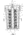
- Fig. 1 represents a cross-sectional view of the filter of the invention taken parallel to the axis of the generally cylindrical filter housing;
- Fig. 2 is a cross-sectional view along line 2-2 of Fig. 1; and
- Fig. 3 is a view comparable to Fig. 2 showing an alternative embodiment of the invention.
- The filter according to the invention is shown in Figs. 1, 2 and 3. The several media used are all contained in a single generally
cylindrical canister 10 comprising alower portion 12 which is generally cup- or bucket-shaped, and acap 14 which is threadedly attached to thelower portion 12 bythreads 16. An O-ring seal 18 is provided to seal thecap 14 to thebody portion 12. As shown in Fig. 1, the 0-ring 18 fits within a groove formed in thecontainer body 12. Typically the 0-ring's cross-sectional diameter is .140 inches, while the groove is .187 inches wide and .110 inches deep (at its lower edge). The inside surface of thecap 14 and the surface of thebody 12 in which the groove is cut have a mating taper, 5° from the vertical in the preferred embodiment. This ensures a good seal without requirement of dimensional tolerances which would be difficult to achieve, particularly where, as is preferred, the cap and body are injection-molded of plastic material. Water enters the interior of thecontainer 10 through aninlet port 20 and exits by way of anoutlet port 22. - Within the
container 10 are three filters. The first or pre-filter 24 is in one preferred embodiment a pleated paper member having pores of five micron diameter. In the example shown, the second filter is a spiral wound activatedcarbon member 26, comprising charcoal on a paper backing. Other means of providing prefiltration and carbon adsorption are within the scope of the invention and are discussed below. The third filter member is a ceramic "candle" 28 which is a closed-ended tube. Thecandle 28 fits within the spiral wrapped activatedcarbon filter 26 which in turn is enclosed by the pleatedpaper filter 24. At the top and bottom of the assembly are provided resilient sealingmembers upper sealing member 30 is generally O-shaped having a hole in its center for theceramic candle 28, while thelower sealing member 32 is circular. These interact with circular dimples, 34 and 36 at the bottom and the top of the canister respectively, and thus provide seals at the two ends of the filter assembly when the cap is tightened down. The water flow is therefore from theinlet port 20, radially inwardly through thepleated paper filter 24 and the wrapped activatedcarbon filter 26, and then inwardly into theceramic candle 28 and outwardly through theoutlet port 22. Uniform radially inward flow is ensured by providing that thepleated paper filter 24 and the activatedcarbon filter 26 do not fit tightly within thecontainer 10, so that a volume of pressurized water is effectively juxtaposed to the exterior of thecarbon filter 26 at all times so that water is continually being pressed inwardly thereagainst. Typically, very little pressure drop is caused by thepleated paper filter 24, so that adequate pressure is exerted to push the water through thecarbon filter 26; similarly the pressure drop across the carbon filter 26-is such that a volume of water is in pressurized contact with the exterior of the ceramic candle, assuring uniformly inward flow. The sizing of thecarbon filter 26 is chosen so that even at the maximum flow rate permissible through theoutlet port 22, the inlet water has adequate residence time within the activatedcarbon member 26 and theceramic candle 28 that effective adsorption, filtration and bacteriostatic action take place. - The invention has been successfully tested in a prototype embodiment, in which the
pleated paper prefilter 24 and the rolled activatedcarbon filter 26 were purchased from the Keystone Filter Division of Met-Pro Corporation of Hatfield, Pennsylvania. It is wel.- understood in the art that the term "activated" means that the carbon is of a granular nature, typically having been heated in a reducing atmosphere, so as to provide a high number of sites for adsorption of all sorts of organic and inorganic materials. Theceramic candle 28 was purchased from Portacel Ltd. of Tonbridge, England under the tradename "British Berkefeld" and is referred to by them as a "Standard Water Filter Element". It has a pore size of 5 microns, and is effective in screening bacteria. Theceramic candle 28 may additionally have a bacteriostatic material, such as silver, preferably in the form of silver nitrate, impregnated throughout the ceramic candle, such that any bacteria which are not filtered out by the ceramic candle, which has a very fine porous structure, are nevertheless killed by the silver such that they do not pose any health problems to those drinking water filtered by the filter of the invention. The candle is hollow, as shown; in this way uniform radially inward flow is ensured. - As will be understood by those skilled in the art, the prefilter and the ceramic filter both act as mechanical filters; that is, providing a maximum pore size such that particles are screened from the water. The carbon, however, acts as an adsorber, i.e., a "chemical filter" by which impurities are chemically attached to bonding sites in the activated carbon member. The physical pore size of the carbon may be on the order of 50 microns.
- As shown in Figures 1 and 2, an
additional screen member 38 may be imposed between the ceramic candle and the activatedcarbon member 26 to prevent erosion of the carbon in use. This might be of polypropylene, for example. An additional paper orcloth interleaf member 40 may also be provided to ensure filtration on the inside surface of the carbon material as well. - The
canister 10 may be provided in bothcap 14 andbody portions 10 with spacedrecesses 42 for interaction with aspanner wrench 44 shown in phantom, so that the threaded connection may be made firmly by means ofthread 18. As shown the ceramic candle may be attached to a threadednipple 46 so that it can be simply threaded into engagement with thecap member 14 and be sealed thereto by O-ring 50. In the prototypical version tested and discussed above, theceramic candle 28 is supplied by Portacel Ltd. with the nipple attached. The threadednipple 46 is used to engage outlet pipe means shown in phantom at 48. - In the presently envisioned preferred embodiment of the invention the
cap 14 andbody portion 12 of thecontainer 10 are both injection molded of a talc-filled polypropylene plastic material.Ribs 12a may be added as shown to ensure uniform cooling of the body portion after molding, to avoid distortion. Theribs 12a also provide a convenient means of mounting of the container; wires riding in the groove between theribs 12a can readily be attached to a wall or the like. - In the successfully tested embodiment of the invention, the relative dimensions of the unit were generally as shown in Figs. 1 and 2. The embodiment tested operated successfully in a household water environment where the typical water pressure was 85 psi static, 55 psi flowing. The overall dimension of the carbon filter assembly is approximarely 4-3/4 inches diameter by 9 inches high. The ceramic filter assembly is typically 2 1/4 inches in diameter by 10-1/2 inches long.The volume of activated carbon is thus about 120 cubic inches, or approximately 1/2 gallon; used in conjunction with 1/8" standard piping, which gives a typical flow rate of 1 gal./min., an average residence time of the water in the carbon on the order of 30 seconds is provided.
- Fig. 3 shows an alternative embodiment of the invention in cross-section. Again, the
body portion 12 of the container holdsprefilter 24,carbon filter 26 andceramic candle 28. However, in this caseadditional baffle members baffles - There are also various other modifications that can be made to the water purification device of the invention which can be selected by those skilled in the art on the basis of the cost of manufacture of the device and the efficacy of filtering provided. For example, it may be desirable for manufacturing convenience to use an extruded carbon tube member rather than a wrapped member as shown in Figs. 1 and 2. Such a carbon tube is sold under the trademark SCHUMASORB by the Universal Porosics Co. of La Grange, Illinois. This expedient would eliminate the
interleaving 40 and theinner screen 38 because it is self-supporting. Another possibility would be simply to use theinner screen 38 as shown in Fig. 2 and place loose granular carbon between this screen and theprefilter 24. This would be particularly easy if the prefilter were a tube formed of a rigid foam material as shown in Fig. 3, such as the melamine foam sold by Corning, Inc. This sort of foam is available in various tubing sizes, for example, a tube having a wall thickness of perhaps 1/2 inch could be used. This would prevent any purging through of contaminants collecting on the prefilter's outer surface, though it is true that such a foam tube has less surface area than does the pleated paper filter shown in Figs. 1 and 2. - It will be appreciated that there has been described a water purification device substantially achieving the objects of the invention discussed above. The design of the several filters used is such that the relative sizings of the carbon and ceramic filters are appropriate for their functions, while means are provided to ensure that the water flow is substantially uniform so that all of the filtration media provided are effectively employed.
- While several preferred embodiments of the invention have been described it should be appreciated that numerous additional modifications and improvements thereto are possible and accordingly that the scope of the invention should not be construed to be limited by the above disclosure but only by the following claims.
Claims (30)
Applications Claiming Priority (2)
| Application Number | Priority Date | Filing Date | Title |
|---|---|---|---|
| US56283683A | 1983-12-19 | 1983-12-19 | |
| US562836 | 1983-12-19 |
Publications (2)
| Publication Number | Publication Date |
|---|---|
| EP0150559A2 true EP0150559A2 (en) | 1985-08-07 |
| EP0150559A3 EP0150559A3 (en) | 1986-10-15 |
Family
ID=24247990
Family Applications (1)
| Application Number | Title | Priority Date | Filing Date |
|---|---|---|---|
| EP84306514A Withdrawn EP0150559A3 (en) | 1983-12-19 | 1984-09-25 | Compact water purifying device |
Country Status (2)
| Country | Link |
|---|---|
| EP (1) | EP0150559A3 (en) |
| JP (1) | JPS60190206A (en) |
Cited By (14)
| Publication number | Priority date | Publication date | Assignee | Title |
|---|---|---|---|---|
| GB2187396A (en) * | 1986-03-07 | 1987-09-09 | Pall Corp | Filter |
| US4828698A (en) * | 1986-03-07 | 1989-05-09 | Pall Corporation | Filtering apparatus |
| EP0364111A1 (en) * | 1988-09-20 | 1990-04-18 | Kabushiki Kaisha Aiaishi | Water purifier |
| FR2638100A1 (en) * | 1988-10-25 | 1990-04-27 | Nalco France Sarl | Apparatus for water treatment |
| GB2238531A (en) * | 1989-12-01 | 1991-06-05 | Byrd Marion O Neal | Nitrate removing domestic water purifier |
| EP0432906A1 (en) * | 1989-12-07 | 1991-06-19 | Fairey Industrial Ceramics Limited | Filter |
| DE4416501A1 (en) * | 1994-05-10 | 1995-11-16 | Judo Wasseraufbereitung | Germ protection for house water filter sieve inserts |
| US5772896A (en) * | 1996-04-05 | 1998-06-30 | Fountainhead Technologies | Self-regulating water purification composition |
| US6254894B1 (en) | 1996-04-05 | 2001-07-03 | Zodiac Pool Care, Inc. | Silver self-regulating water purification compositions and methods |
| DE10335343A1 (en) * | 2003-08-01 | 2005-03-03 | Itn Nanovation Gmbh | Ceramic filter element for cleaning water |
| WO2007107719A1 (en) * | 2006-03-17 | 2007-09-27 | Fairey Industrial Ceramics Limited | Treatment assemblies |
| WO2009087670A2 (en) * | 2008-01-04 | 2009-07-16 | Basic Water Needs B.V. | Gravity operating ceramic water filter |
| DE102009031358A1 (en) * | 2009-07-02 | 2011-01-05 | Hydac Process Technology Gmbh | Filter device and filter element assembly for use in the filter device |
| CN111601776A (en) * | 2017-10-30 | 2020-08-28 | 晟尔私人有限公司 | Water filter with water nutrient enrichment function |
Families Citing this family (5)
| Publication number | Priority date | Publication date | Assignee | Title |
|---|---|---|---|---|
| JPH0352155Y2 (en) * | 1986-07-04 | 1991-11-11 | ||
| JPS63278512A (en) * | 1987-05-08 | 1988-11-16 | Eiichi Sugiura | Filter for oil or water or the like |
| CN106621518A (en) * | 2016-09-30 | 2017-05-10 | 佛山市美的清湖净水设备有限公司 | Composite filter element for refrigerator and refrigerator with same |
| JP6580775B1 (en) * | 2018-12-14 | 2019-09-25 | Bs—1グローバルシステムズ株式会社 | Filter, dampening water circulation system, and dampening water circulation method |
| JP2020093521A (en) * | 2019-08-07 | 2020-06-18 | Bs—1グローバルシステムズ株式会社 | Filter, circulation system of dampening water, circulation method of dampening water, and use method of melamine resin foam |
Citations (5)
| Publication number | Priority date | Publication date | Assignee | Title |
|---|---|---|---|---|
| CH339888A (en) * | 1954-06-23 | 1959-07-15 | Katadyn Ges Mbh Deutsche | Device for the treatment of liquids, in particular drinking water |
| US3637078A (en) * | 1970-06-22 | 1972-01-25 | Gould Inc | Directional flow fluid filter |
| US3675776A (en) * | 1970-12-16 | 1972-07-11 | Philip Campo | Filter device |
| DE3001674A1 (en) * | 1980-01-18 | 1981-07-23 | Fichtel & Sachs Ag, 8720 Schweinfurt | Drinking water filter - with filter element including acidulating and biocidal substances |
| DE3103723A1 (en) * | 1981-02-04 | 1982-09-02 | Robert Bosch Gmbh, 7000 Stuttgart | Filter for liquids |
-
1984
- 1984-09-25 EP EP84306514A patent/EP0150559A3/en not_active Withdrawn
- 1984-10-18 JP JP59219343A patent/JPS60190206A/en active Pending
Patent Citations (5)
| Publication number | Priority date | Publication date | Assignee | Title |
|---|---|---|---|---|
| CH339888A (en) * | 1954-06-23 | 1959-07-15 | Katadyn Ges Mbh Deutsche | Device for the treatment of liquids, in particular drinking water |
| US3637078A (en) * | 1970-06-22 | 1972-01-25 | Gould Inc | Directional flow fluid filter |
| US3675776A (en) * | 1970-12-16 | 1972-07-11 | Philip Campo | Filter device |
| DE3001674A1 (en) * | 1980-01-18 | 1981-07-23 | Fichtel & Sachs Ag, 8720 Schweinfurt | Drinking water filter - with filter element including acidulating and biocidal substances |
| DE3103723A1 (en) * | 1981-02-04 | 1982-09-02 | Robert Bosch Gmbh, 7000 Stuttgart | Filter for liquids |
Cited By (20)
| Publication number | Priority date | Publication date | Assignee | Title |
|---|---|---|---|---|
| GB2187396A (en) * | 1986-03-07 | 1987-09-09 | Pall Corp | Filter |
| US4828698A (en) * | 1986-03-07 | 1989-05-09 | Pall Corporation | Filtering apparatus |
| GB2187396B (en) * | 1986-03-07 | 1990-03-21 | Pall Corp | Filtering apparatus |
| EP0364111A1 (en) * | 1988-09-20 | 1990-04-18 | Kabushiki Kaisha Aiaishi | Water purifier |
| US5071551A (en) * | 1988-09-20 | 1991-12-10 | Kabushiki Kaisha Aiaishi | Water purifier |
| FR2638100A1 (en) * | 1988-10-25 | 1990-04-27 | Nalco France Sarl | Apparatus for water treatment |
| GB2238531A (en) * | 1989-12-01 | 1991-06-05 | Byrd Marion O Neal | Nitrate removing domestic water purifier |
| EP0432906A1 (en) * | 1989-12-07 | 1991-06-19 | Fairey Industrial Ceramics Limited | Filter |
| DE4416501A1 (en) * | 1994-05-10 | 1995-11-16 | Judo Wasseraufbereitung | Germ protection for house water filter sieve inserts |
| US6254894B1 (en) | 1996-04-05 | 2001-07-03 | Zodiac Pool Care, Inc. | Silver self-regulating water purification compositions and methods |
| US5772896A (en) * | 1996-04-05 | 1998-06-30 | Fountainhead Technologies | Self-regulating water purification composition |
| DE10335343A1 (en) * | 2003-08-01 | 2005-03-03 | Itn Nanovation Gmbh | Ceramic filter element for cleaning water |
| WO2007107719A1 (en) * | 2006-03-17 | 2007-09-27 | Fairey Industrial Ceramics Limited | Treatment assemblies |
| GB2436076B (en) * | 2006-03-17 | 2011-07-13 | Fairey Ceramics | Fluid treatment assemblies |
| US8128823B2 (en) | 2006-03-17 | 2012-03-06 | Fairey Industrial Ceramics Limited | Treatment assemblies |
| WO2009087670A2 (en) * | 2008-01-04 | 2009-07-16 | Basic Water Needs B.V. | Gravity operating ceramic water filter |
| WO2009087670A3 (en) * | 2008-01-04 | 2009-09-03 | Basic Water Needs B.V. | Gravity operating ceramic water filter |
| DE102009031358A1 (en) * | 2009-07-02 | 2011-01-05 | Hydac Process Technology Gmbh | Filter device and filter element assembly for use in the filter device |
| CN111601776A (en) * | 2017-10-30 | 2020-08-28 | 晟尔私人有限公司 | Water filter with water nutrient enrichment function |
| CN111601776B (en) * | 2017-10-30 | 2022-09-20 | 晟尔私人有限公司 | Water filter with water nutrient enrichment function |
Also Published As
| Publication number | Publication date |
|---|---|
| EP0150559A3 (en) | 1986-10-15 |
| JPS60190206A (en) | 1985-09-27 |
Similar Documents
| Publication | Publication Date | Title |
|---|---|---|
| US4540489A (en) | Compact water purifying device | |
| EP0150559A2 (en) | Compact water purifying device | |
| US5518613A (en) | Portable water purifying and drinking device | |
| US7507338B2 (en) | Universal water purifier unit assembly device | |
| US5126044A (en) | Iodine resin/carbon water purification system | |
| US5830360A (en) | Pour through and pitcher mounted water filter for removal of parasite cysts, bacteria and viruses and method of filtrating water | |
| US4711723A (en) | Water purification system | |
| US7396461B2 (en) | Filter cartridge for gravity-fed water treatment device | |
| EP0975552B1 (en) | Filter cartridge for gravity-fed water treatment devices | |
| US4713175A (en) | Water purifier comprising stages mounted side-by-side to unitary header | |
| US6004460A (en) | Portable water filtration bottle | |
| EP1536875B1 (en) | Encapsulated filter cartridge | |
| US20160250573A1 (en) | Multi-layered composite filter media and pleated filter element constructed therefrom | |
| US20040206682A1 (en) | Filter assembly utilizing carbon block and pleated filter element | |
| WO1997006109A1 (en) | Portable water purification device | |
| JP3242395B2 (en) | Water purifier | |
| WO2000009449A2 (en) | Portable water filtration system | |
| KR200317263Y1 (en) | Filter cartridge for device of clean water | |
| JP3069415B2 (en) | Water purifier | |
| KR200242688Y1 (en) | A fiter cartridge of water purifier | |
| JPH11128910A (en) | Microminiature portable water filter |
Legal Events
| Date | Code | Title | Description |
|---|---|---|---|
| PUAI | Public reference made under article 153(3) epc to a published international application that has entered the european phase |
Free format text: ORIGINAL CODE: 0009012 |
|
| AK | Designated contracting states |
Designated state(s): AT BE CH DE FR GB IT LI LU NL SE |
|
| PUAL | Search report despatched |
Free format text: ORIGINAL CODE: 0009013 |
|
| AK | Designated contracting states |
Kind code of ref document: A3 Designated state(s): AT BE CH DE FR GB IT LI LU NL SE |
|
| STAA | Information on the status of an ep patent application or granted ep patent |
Free format text: STATUS: THE APPLICATION IS DEEMED TO BE WITHDRAWN |
|
| 18D | Application deemed to be withdrawn |
Effective date: 19861001 |
|
| RIN1 | Information on inventor provided before grant (corrected) |
Inventor name: GILES, WILLIAM E. Inventor name: TOWFIGH, KIEVAN Inventor name: BARNARD, ROYAL W. |