EP0151068A2 - Cooling system for electronic circuit device - Google Patents
Cooling system for electronic circuit device Download PDFInfo
- Publication number
- EP0151068A2 EP0151068A2 EP85400097A EP85400097A EP0151068A2 EP 0151068 A2 EP0151068 A2 EP 0151068A2 EP 85400097 A EP85400097 A EP 85400097A EP 85400097 A EP85400097 A EP 85400097A EP 0151068 A2 EP0151068 A2 EP 0151068A2
- Authority
- EP
- European Patent Office
- Prior art keywords
- heat transfer
- cooling system
- coolant
- circuit component
- compliance
- Prior art date
- Legal status (The legal status is an assumption and is not a legal conclusion. Google has not performed a legal analysis and makes no representation as to the accuracy of the status listed.)
- Granted
Links
Images


Classifications
-
- H—ELECTRICITY
- H05—ELECTRIC TECHNIQUES NOT OTHERWISE PROVIDED FOR
- H05K—PRINTED CIRCUITS; CASINGS OR CONSTRUCTIONAL DETAILS OF ELECTRIC APPARATUS; MANUFACTURE OF ASSEMBLAGES OF ELECTRICAL COMPONENTS
- H05K7/00—Constructional details common to different types of electric apparatus
- H05K7/20—Modifications to facilitate cooling, ventilating, or heating
-
- H—ELECTRICITY
- H01—ELECTRIC ELEMENTS
- H01L—SEMICONDUCTOR DEVICES NOT COVERED BY CLASS H10
- H01L23/00—Details of semiconductor or other solid state devices
- H01L23/34—Arrangements for cooling, heating, ventilating or temperature compensation ; Temperature sensing arrangements
- H01L23/42—Fillings or auxiliary members in containers or encapsulations selected or arranged to facilitate heating or cooling
- H01L23/433—Auxiliary members in containers characterised by their shape, e.g. pistons
- H01L23/4332—Bellows
-
- H—ELECTRICITY
- H01—ELECTRIC ELEMENTS
- H01L—SEMICONDUCTOR DEVICES NOT COVERED BY CLASS H10
- H01L23/00—Details of semiconductor or other solid state devices
- H01L23/34—Arrangements for cooling, heating, ventilating or temperature compensation ; Temperature sensing arrangements
- H01L23/42—Fillings or auxiliary members in containers or encapsulations selected or arranged to facilitate heating or cooling
- H01L23/433—Auxiliary members in containers characterised by their shape, e.g. pistons
- H01L23/4336—Auxiliary members in containers characterised by their shape, e.g. pistons in combination with jet impingement
-
- H—ELECTRICITY
- H01—ELECTRIC ELEMENTS
- H01L—SEMICONDUCTOR DEVICES NOT COVERED BY CLASS H10
- H01L2224/00—Indexing scheme for arrangements for connecting or disconnecting semiconductor or solid-state bodies and methods related thereto as covered by H01L24/00
- H01L2224/01—Means for bonding being attached to, or being formed on, the surface to be connected, e.g. chip-to-package, die-attach, "first-level" interconnects; Manufacturing methods related thereto
- H01L2224/42—Wire connectors; Manufacturing methods related thereto
- H01L2224/47—Structure, shape, material or disposition of the wire connectors after the connecting process
- H01L2224/48—Structure, shape, material or disposition of the wire connectors after the connecting process of an individual wire connector
- H01L2224/4805—Shape
- H01L2224/4809—Loop shape
- H01L2224/48091—Arched
-
- H—ELECTRICITY
- H01—ELECTRIC ELEMENTS
- H01L—SEMICONDUCTOR DEVICES NOT COVERED BY CLASS H10
- H01L2224/00—Indexing scheme for arrangements for connecting or disconnecting semiconductor or solid-state bodies and methods related thereto as covered by H01L24/00
- H01L2224/01—Means for bonding being attached to, or being formed on, the surface to be connected, e.g. chip-to-package, die-attach, "first-level" interconnects; Manufacturing methods related thereto
- H01L2224/42—Wire connectors; Manufacturing methods related thereto
- H01L2224/47—Structure, shape, material or disposition of the wire connectors after the connecting process
- H01L2224/48—Structure, shape, material or disposition of the wire connectors after the connecting process of an individual wire connector
- H01L2224/481—Disposition
- H01L2224/48151—Connecting between a semiconductor or solid-state body and an item not being a semiconductor or solid-state body, e.g. chip-to-substrate, chip-to-passive
- H01L2224/48221—Connecting between a semiconductor or solid-state body and an item not being a semiconductor or solid-state body, e.g. chip-to-substrate, chip-to-passive the body and the item being stacked
- H01L2224/48225—Connecting between a semiconductor or solid-state body and an item not being a semiconductor or solid-state body, e.g. chip-to-substrate, chip-to-passive the body and the item being stacked the item being non-metallic, e.g. insulating substrate with or without metallisation
- H01L2224/48227—Connecting between a semiconductor or solid-state body and an item not being a semiconductor or solid-state body, e.g. chip-to-substrate, chip-to-passive the body and the item being stacked the item being non-metallic, e.g. insulating substrate with or without metallisation connecting the wire to a bond pad of the item
-
- H—ELECTRICITY
- H01—ELECTRIC ELEMENTS
- H01L—SEMICONDUCTOR DEVICES NOT COVERED BY CLASS H10
- H01L2224/00—Indexing scheme for arrangements for connecting or disconnecting semiconductor or solid-state bodies and methods related thereto as covered by H01L24/00
- H01L2224/01—Means for bonding being attached to, or being formed on, the surface to be connected, e.g. chip-to-package, die-attach, "first-level" interconnects; Manufacturing methods related thereto
- H01L2224/42—Wire connectors; Manufacturing methods related thereto
- H01L2224/47—Structure, shape, material or disposition of the wire connectors after the connecting process
- H01L2224/48—Structure, shape, material or disposition of the wire connectors after the connecting process of an individual wire connector
- H01L2224/484—Connecting portions
- H01L2224/4847—Connecting portions the connecting portion on the bonding area of the semiconductor or solid-state body being a wedge bond
- H01L2224/48472—Connecting portions the connecting portion on the bonding area of the semiconductor or solid-state body being a wedge bond the other connecting portion not on the bonding area also being a wedge bond, i.e. wedge-to-wedge
-
- H—ELECTRICITY
- H01—ELECTRIC ELEMENTS
- H01L—SEMICONDUCTOR DEVICES NOT COVERED BY CLASS H10
- H01L2224/00—Indexing scheme for arrangements for connecting or disconnecting semiconductor or solid-state bodies and methods related thereto as covered by H01L24/00
- H01L2224/73—Means for bonding being of different types provided for in two or more of groups H01L2224/10, H01L2224/18, H01L2224/26, H01L2224/34, H01L2224/42, H01L2224/50, H01L2224/63, H01L2224/71
- H01L2224/732—Location after the connecting process
- H01L2224/73201—Location after the connecting process on the same surface
- H01L2224/73203—Bump and layer connectors
- H01L2224/73204—Bump and layer connectors the bump connector being embedded into the layer connector
Definitions
- the present invention relates to a cooling system for an electronic circuit device. More particularly, it relates to a printed circuit board holding electronic circuit components, wherein these components are cooled by a cooling system that includes a cooling module or a series of cooling modules for removing the heat dissipated from the components and transferring it to a coolant flowing in a passage.
- a heat transfer element such as a heat transfer plate or a heat transfer piston
- the circuit components such as integrated circuits (IC), large scale integrated circuits (LSI), and semiconductors
- the heat transfer elements are directly or indirectly exposed to a coolant (usually a gaseous coolant), in such a manner that the heat removed from the circuit components is transferred to the coolant by means of the corresponding heat transfer element.
- the primary object of the present invention is to eliminate the aforementioned drawbacks of the prior art by providing a cooling system for an electronic circuit device which can effectively, stably, and uniformly cool the circuit components.
- a compliance means between a first heat transfer means which is exposed to a coolant and the circuit component to be cooled.
- the compliance means establishes a compliant surface contact between the first heat transfer means and the circuit component, in that the compliance means is pressed against the circuit component by an elastic means, such as spring, diaphragm, bellows, or any combination thereof.
- a second heat transfer means is additionally provided on and secured to the circuit component.
- the compliance means is located between the first and second heat transfer means.
- each cooling module comprises a first transfer means exposed to a common flow of the coolant, a second heat transfer means secured to the corresponding circuit component, and a compliance means between the first and second heat transfer means for establishing a compliant contact therebetween.
- the first heat transfer means and the compliance means are together pressed against the corresponding circuit components by an elastic means connected to the first heat tranfer means, through the second heat transfer means.
- the second heat transfer means can be dispensed with, and in the alternative, the compliance means pressed directly against the corresponding circuit components.
- the cooling module has a heat transfer plate 3 connected to a passage (coolant header) 1 in which a coolant flows, by means of a bellows 5.
- the heat transfer plate 3 is exposed to the flow of the coolant, as shown by arrows.
- the plate 3 is pressed against an electronic circuit component 7, such as an IC, LSI, or semiconductor provided on a printed circuit board 9, by means of the bellows 5 and the hydraulic pressure of the coolant.
- the component 7 is bonded to the printed circuit board 9 by, for example, solder balls 11.
- solder balls 11 When the heat transfer plate 3 is pressed into contact with the component 7, the heat dissipated from the component 7 can be removed therefrom by the heat transfer plate 9 and transferred to the coolant.
- the heat transfer plate is replaced by a heat transfer piston 13 biased by a spring 15.
- the piston 13 is pressed onto the circuit component 7 on the printed circuit board 9, by the spring 15.
- the coolant flows in the passages 11 provided in the coolant header 12.
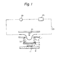
- Figure 1 shows an embodiment of the present invention in which the coolant module has a passage 1 for the coolant flow.
- the coolant can be gas but is not limited thereto, and may be a liquid, such as water, liquid fluorocarbon, or even a liquid metal such as mercury or gallium.
- the passage 1 is preferably a part of a recirculation line 23 having therein a pump 29 and a heat radiator or heat exchanger 25.
- a first heat transfer plate 3 is connected to the passage 1 by means of a bellows 5 attached to the passage 1.
- the passage 1 has a deflector 21 extending toward the first heat transfer plate 3.
- a coolant recirculation zone 32 is defined in the bellows 5, in which zone 32 the first heat transfer plate 3 is exposed to the coolant at one side face of the plate 3.
- the direction of the coolant flow in the passage 1 is changed by the deflector 21, which can be dispensed with, and thus the heat is removed from the first heat transfer plate 3 in the circulation zone 32.
- a heat transferring compliant member 31 is provided between the first heat transfer plate 3 and the circuit component 7.
- the sheet-like or plate-like compliant member 31 is secured to the outer side face of the first heat tranfer plate 3.
- the compliant member 31 can be secured to the circuit component 7 on the printed circuit board 9.
- the compliant member 31 can be secured to the first heat transfer plate 3 or the circuit component 7 by means of a proper adhesive.
- the compliant member 31 will come into a full compliant contact with the circuit component 7, even when the plate 3 and/or the circuit component has an uneven or irregular surface.
- the compliant member 31 can be made of elastic, thermodeformable, compressible, or thermocompressible materials which will deform or are compressed when heated or subjected to pressure.
- the compliant member 31 is preferably made of elastic materials having a high heat conductivity.
- thermodeformable materials used for the compliant member 31 a polyolefin elastomer which will soften at a temperature of approximately 80°C, or a combined material containing, for example, a polyolefin elastomer as a binder and a metal oxide filler, such as alumina (A 2 0 3 ), boron nitride (BN), or beryllia (BeO) can be used.
- a binder such as silicone elastomer or polyolefin elastomer
- a ceramic filler such as alumina, boron nitride, or beryllia
- the compliant member 31 also can be made of high heat conductive plastic materials or soft metals, such as indium alloy or gallium alloy.
- the compliant member 31 is preferably made of electrical insulation materials or has an electrical insulation layer 30 on one or both side face(s) to insulate the cooling module from, for example, a substrate of a circuit component, for example, an ECL circuit.
- the first heat transfer plate 3 is made of materials having a high heat conductivity, such as copper or copper alloy.
- a second heat transfer plate 33 is provided between the compliant member 31 and the circuit component 7.
- the second plate 33 can be secured to the circuit component 7, by soldering or die bonding, as shown in Fig. 2.
- the second plate 33 has a larger surface area than the corresponding circuit component 7, and thus the second plate 33 has a large heat transfer surface.
- the second plate 33 is preferably made of a material having the same thermal expansion coefficient as that of the corresponding circuit component 7.
- the second plate 33 can be made of an Mo or Mo/Cu clad or the like.
- the bellows 5 can be made by a known hydraulic forming method, welding method, or electric deposit forming method.
- the electric deposit method referred to is a process in which an aluminium die is first coated with nickel and the aluminium die is then dissolved, so that only the nickel coating layer remains, which layer forms a bellows.
- the bellows 5 can be replaced by a diaphragm 45, as shown in Fig. 12, which will be described later.
- the circuit component 7 can be bonded directly to the printed circuit board 9 by electrically conductive solder balls 11, as shown in Fig. 1.
- the circuit component 7 is secured to the second heat transfer plate 33 supported on a wiring board 39, which is in turn supported on a support 37 usually made of an insulation material.
- the circuit component 7 is a electrically connected to the wiring board 39 by means of wires or leads 41.
- the wiring board 39 is electrically connected to conductor patterns 47 provided on the printed circuit board 9 by means of lead frames 35.
- Figures 3 to 7 show different arrangements of the circuit device; in which Fig. 3 shows a hermetic seal package construction of the circuit device.
- the circuit component 7 is housed in a hermetic sealing package having a hermetic sealing lid 43 connected to the support 37 and secured to the printed circuit board 9.
- the second heat transfer plate 33 has a stepped portion 33a to which the circuit component 7 is secured.
- the lead frames 35 are dispensed with. Instead, the wiring board 39 is electrically connected to the conductor patterns 47 of the printed circuit board 9 by means of the conductive solder balls 11.
- the circuit component 7 is housed in the hermetic sealing package having the hermetic sealing lid 43 secured to the wiring board 39 which supports the second heat transfer plate 33.
- the circuit component 7 is directly bonded to the printed circuit board 9 by means of the conductive solder balls 11. Namely, the bare chip of the circuit component 7 per se is located on the printed circuit board without holding or supporting means.
- the component 7 is bonded to the second heat transfer plate 33 by means of a soldering layer or Au-Si eutectic alloy layer 51 in a conventional die bonding method.
- the die bonding of the component 7 to the second plate 33 can be effected either before or after the component 7 is soldered to the printed circuit board 9.
- the melting point of the layer 51 may be higher or lower than that of the solder balls 11.
- the second heat transfer plate 33 is supported on and by standoff supports 53 provided on the printed circuit board 9.
- the circuit component 7 is directly and electrically connected to the printed circuit board 9.
- the component 7 is adhered to the second plate 33 by means of a heat conductive bonding, such as low temperature solder 55.
- the standoff supports 53 receive the pressure from the first heat transfer plate 3 (Fig. 1 or 2), and are secured to the second plate 33 by means of the proper adhesive or solder.
- the circuit component e.g., a Tape Aided Bonding (TAB) chip 7 is bonded to the second plate 33 by means of bonding layer 55, such as a low temperature solder layer.
- the chip 7 is electrically connected to the printed circuit board 9 by means of TAB leads 57, in place of the solder balls.
- TAB Tape Aided Bonding
- Figure 8 shows another embodiment of a cooling module according to the present invention.
- the passage 1 has therein a partition wall 63 extending along the length of the passage 1.
- the partition wall 63 divides the inside area of the passage 1 into two sections; one la for the flow of coolant coming from the pump 29, and the other lb for the flow of coolant returning to the pump.
- the partition wall 63 has a nozzle 61 having a nozzle opening 65 of an inner diameter D.
- the nozzle opening opens into the circulation zone 32 formed in the bellows 5.
- the nozzle 61 extends toward the center of the circulation zone 32, and accordingly, the center of the first plate 3, so that the flow of the coolant ejected from the nozzle 61 impinges on the first plate 3, and is then returned into the return passage section lb; thus effectively removing the heat from the first heat tranfer plate 3.
- the nozzle can realize the so-called jet cooling.
- the flow velocity of the jet is, for example, 0.5 m/s to 3 m/s.
- the coefficient of heat transfer between the first plate 3 and the coolant jet is 15,000 ft. 30,000 Kcal/m 2 h°C.
- Figure 9 shows a variant of Fig. 8, in which the first plate 3 has a ridged surface 3a which increases the surface area available for the heat transfer.
- Figure 10 shows another embodiment of a cooling module, in which the pressure from the bellows 5 on the first plate 3 is augmented by an additional spring 71 located between the passage 1 and the first plate 3.
- the provision of the spring 71 decreases the initial spring load of the bellows 5 and also decreases the possibility of plastic deformation of the bellows 5.
- the bellows 5 has O-ring-like upper terminal ends 5a secured to the passage 1 by means of sealing brackets 73.
- the spring 71 can be also used to augment the pressure of the diaphragm 45 (Fig. 11) provided in place of the bellows 5 as the pressing means for the first plate 3.
- hydraulic pressure of the coolant in place of the spring 71.
- the hydraulic pressure of the coolant can be created and controlled by the pump 29.
- the first plate 3 and the compliant member 31 are pressed against the circuit component or the second plate 33, if used, by the spring force of the bellows 5 even when the hydraulic pressure is released or when there is no coolant in the circulation zone 32, so that no foreign material can enter the contact surface between the compliant member 31 and the circuit component 7 (Fig. 1) or the second plate 33 (Fig. 2) when the pump is not operative or the electronic circuit device is in a non-operational state.
- FIG 11 shows a modification of a cooling module according to the present invention.
- a heat transfer stud 75 is additionally provided on the first plate 3.
- the stud 75 is rigidly connected to the first plate 3 to transfer heat from the first plate 3 to the coolant.
- the stud 75 has at its upper end cooling fins 77 which extend in the flow of the coolant in the passage 1 in parallel to the direction of flow of the coolant.
- the stud 75 is preferably solid, so that the heat transferred thereto from the first plate 3 is effectively transferred to the coolant through the fins 77.
- Figure 12 shows a variant of the elastic pressure means for the first plate 3. Namely, in Fig. 12, the bellows 5 in the aforementioned embodiments are replaced with the diaphragm 45.
- the diaphragm 45 is rigidly connected to the passage 1 and the first heat transfer plate 3.
- the diaphragm 45 applies pressure to the first plate 3 and the compliant member 31, forcing them onto the second plate 33, or onto the circuit component 7 when the second plate 33 is omitted.
- the heat transfer solid stud 75 having the fins 77 is provided on the first plate 3.
- a stud having a shorter vertical length can be used, in comparison with that shown in Fig. 11, and accordingly, a higher heat transfer efficiency is obtained.
- the distance between the passage 1 and the circuit component 7 or the second plate 33 is smaller than that shown in Fig. 11, since the diaphragm 45 lies on a plane substantially flush with the passage 1.
- the compliant member 31 is provided between the first heat transfer plate 3 and the second heat transfer plate 33 or the circuit component 7, unevenness of the surface or deflection of the first heat transfer plate 3 and/or the second heat transfer plate 33 can be effectively absorbed by the compliant member 31, thus resulting in a decrease in the number of air cavities 100, which have a large thermal resistance, between the first and second plates 3, 33 or between the first plate 3 and the circuit component 7.
- the compliant member 31 establishes a compliant contact between the first and second plates 3, 33, which inevitably have irregular or uneven surfaces and thus would otherwise increase the number of air cavities therebetween, as shown in Fig. 15.
- the inclination can be effectively absorbed by the compliant member 31, as shown in Fig. 13, and because the second heat transfer plate 33 is larger than the corresponding circuit component, the heat transfer efficiency thereof from the circuit component 7 is increased.
- the above inclination may be caused by the inclination of the bellows 5 or diaphragm 45, and this can also be absorbed by the compliant member 31.
- Figure 14 shows a series of cooling modules for the corresponding circuit components 7. Although a large number of circuit components are usually arranged on the printed circuit board 9, each of the cooling modules mentioned above can be provided for each circuit component. Preferably, the passage 1 for the coolant is common to all cooling modules.
- the arrangement shown in Fig. 14 includes a series of cooling modules and is substantially identical to the arrangement shown in Fig. 8.
- the passage 1 is held by the supporting frames 81 rigidly connected to the printed circuit board 9 by keep plates 85, which are in turn secured to the supporting frames 81 by set screws 83.
- the space 87 preferably contains an inert gas such as He or other gas, such as H2, which has a high heat conductivity.
- the gas contained in the space 87 serves as a heat transfer agent between the circuit component and the coolant in the passage 1.
- the heat of the circuit component can be also transferred to the coolant in the passage 1 or in the bellows 5 through the pipe of the passage or the bellows by means of the gas contained in the space 87, in addition to the aforementioned heat transfer route of the first plate 3 and the compliant member 31.
- the space 87 is preferably sealed by seal members such as O-rings, C-rings, or spring-biased C-rings 89 provided between the printed circuit board 9 and the frames 81.
- the compliant member can increase the allowable heat transfer between the circuit component and the first and/or second heat transfer plates and decrease the thermal contact resistance therebetween, resulting in a high heat transfer ratio and a high cooling efficiency.
Abstract
Description
- The present invention relates to a cooling system for an electronic circuit device. More particularly, it relates to a printed circuit board holding electronic circuit components, wherein these components are cooled by a cooling system that includes a cooling module or a series of cooling modules for removing the heat dissipated from the components and transferring it to a coolant flowing in a passage.
- In conventional cooling modules for an electronic circuit device a heat transfer element, such as a heat transfer plate or a heat transfer piston, is placed in direct contact with the circuit components, such as integrated circuits (IC), large scale integrated circuits (LSI), and semiconductors, by pressure from a spring or a bellows, to remove the heat dissipated from these circuit components. The heat transfer elements are directly or indirectly exposed to a coolant (usually a gaseous coolant), in such a manner that the heat removed from the circuit components is transferred to the coolant by means of the corresponding heat transfer element. However, these prior arts have the following drawbacks: a) the surface area for an effective heat transfer between the heat transfer elements and the corresponding circuit components is relatively small; b) complete surface contact therebetween cannot be achieved, resulting in a large and non-uniform thermal contact resistance; and c) any change in the pressure from the spring or bellows leads directly to a change in the thermal contact resistance, resulting in an unstable thermal contact resistance. All of the above are the causes of a large loss in the heat transfer efficiency.
- The primary object of the present invention is to eliminate the aforementioned drawbacks of the prior art by providing a cooling system for an electronic circuit device which can effectively, stably, and uniformly cool the circuit components.
- To achieve the object mentioned above, according to the present invention, there is provided a compliance means between a first heat transfer means which is exposed to a coolant and the circuit component to be cooled. The compliance means establishes a compliant surface contact between the first heat transfer means and the circuit component, in that the compliance means is pressed against the circuit component by an elastic means, such as spring, diaphragm, bellows, or any combination thereof.
- According to another embodiment of the present invention, a second heat transfer means is additionally provided on and secured to the circuit component. In this embodiment, the compliance means is located between the first and second heat transfer means.
- According to still another embodiment of the present invention, there is provided a series of cooling modules, each module being provided for the corresponding circuit element or elements. Each cooling module comprises a first transfer means exposed to a common flow of the coolant, a second heat transfer means secured to the corresponding circuit component, and a compliance means between the first and second heat transfer means for establishing a compliant contact therebetween. The first heat transfer means and the compliance means are together pressed against the corresponding circuit components by an elastic means connected to the first heat tranfer means, through the second heat transfer means. Alternatively, the second heat transfer means can be dispensed with, and in the alternative, the compliance means pressed directly against the corresponding circuit components.
- Other features, properties and technical advantages of the present invention will become apparent from the description given below with reference to the drawings, in which:
- Figure 1 is a schematic sectional view of a cooling system according to the present invention;
- Fig. 2 is a view similar to Fig. 1, but according to another embodiment of the present invention;
- Fig. 3 is a partial sectional view of a different arrangement of an electronic circuit device to which the present invention is to be applied;
- Figs. 4-7 are other arrangements of an electronic circuit device, different from Fig. 3;
- Figs. 8-12 are schematic sectional views of four different embodiments of cooling modules, from a cooling module shown in Fig. 2;
- Fig. 13 is a schematic sectional view of an arrangement the same as that shown in Fig. 2, but with the cooling module in an inclined state, for explaining the technical effect of the present invention;
- Fig. 14 is a schematic view of an arrangement of a series of cooling modules, according to another embodiment of the present invention;
- Fig. 15 is an enlarged sectional view of a compliant member arranged between the first and second heat transfer plates, according to the present invention; and,
- Figs. 16 and 17 are views of arrangements of cooling systems according to the prior art.
- First, the prior art will be discussed with reference to Fig. 16, in which the cooling module has a
heat transfer plate 3 connected to a passage (coolant header) 1 in which a coolant flows, by means of abellows 5. Theheat transfer plate 3 is exposed to the flow of the coolant, as shown by arrows. Theplate 3 is pressed against anelectronic circuit component 7, such as an IC, LSI, or semiconductor provided on a printedcircuit board 9, by means of thebellows 5 and the hydraulic pressure of the coolant. - The
component 7 is bonded to the printedcircuit board 9 by, for example,solder balls 11. When theheat transfer plate 3 is pressed into contact with thecomponent 7, the heat dissipated from thecomponent 7 can be removed therefrom by theheat transfer plate 9 and transferred to the coolant. - In a different known arrangement as shown in Fig. 17, the heat transfer plate is replaced by a
heat transfer piston 13 biased by aspring 15. Thepiston 13 is pressed onto thecircuit component 7 on the printedcircuit board 9, by thespring 15. The coolant flows in thepassages 11 provided in thecoolant header 12. - In the arrangement shown in Fig. 16, however, since the
heat transfer plate 3 is the same size as thecircuit component 7, the heat transfer surface is small. In addition, theplate 3 cannot come into complete surface contact with thecomponent 7, due to unevenness of the surface of the plate 3 (and the component 7), and, accordingly, the thermal contact resistance increases and becomes unstable and non-uniform. - Furthermore, when the pressure exerted on the
component 9 by thebellows 5 and by the coolant fluctuates, the fluctuation is a direct cause of a change in the thermal contact resistance. - On the other hand, in the arrangement shown in Fig. 17, there is a large loss in heat tranfer efficiency (heat conductivity) in the
coolant header 12. In addition to the foregoing, since the arrangement of Fig. 17 has a relatively large number of thermal connecting portions between thepiston 13 and theheader 12, in comparison with the arrangement of Fig. 16, a relatively large heat transfer loss must be expected. Therefore, the arrangement shown in Fig. 17 must use a gaseous coolant having a high heat conductivity, such as H2 or He, thus resulting in the necessity for providing a seal mechanism for the coolant gas. - These drawbacks of the prior art can be eliminated by the present invention, as shown below.
- Figure 1 shows an embodiment of the present invention in which the coolant module has a
passage 1 for the coolant flow. - The coolant can be gas but is not limited thereto, and may be a liquid, such as water, liquid fluorocarbon, or even a liquid metal such as mercury or gallium. The
passage 1 is preferably a part of arecirculation line 23 having therein apump 29 and a heat radiator orheat exchanger 25. - A first
heat transfer plate 3 is connected to thepassage 1 by means of abellows 5 attached to thepassage 1. Thepassage 1 has adeflector 21 extending toward the firstheat transfer plate 3. Acoolant recirculation zone 32 is defined in thebellows 5, in whichzone 32 the firstheat transfer plate 3 is exposed to the coolant at one side face of theplate 3. - The direction of the coolant flow in the
passage 1 is changed by thedeflector 21, which can be dispensed with, and thus the heat is removed from the firstheat transfer plate 3 in thecirculation zone 32. - According to the present invention, a heat transferring
compliant member 31 is provided between the firstheat transfer plate 3 and thecircuit component 7. In the illustrated embodiment, the sheet-like or plate-likecompliant member 31 is secured to the outer side face of the firstheat tranfer plate 3. Alternatively, thecompliant member 31 can be secured to thecircuit component 7 on the printedcircuit board 9. - The
compliant member 31 can be secured to the firstheat transfer plate 3 or thecircuit component 7 by means of a proper adhesive. - The
compliant member 31 will come into a full compliant contact with thecircuit component 7, even when theplate 3 and/or the circuit component has an uneven or irregular surface. Thecompliant member 31 can be made of elastic, thermodeformable, compressible, or thermocompressible materials which will deform or are compressed when heated or subjected to pressure. Thecompliant member 31 is preferably made of elastic materials having a high heat conductivity. As the thermodeformable materials used for thecompliant member 31, a polyolefin elastomer which will soften at a temperature of approximately 80°C, or a combined material containing, for example, a polyolefin elastomer as a binder and a metal oxide filler, such as alumina (A 203), boron nitride (BN), or beryllia (BeO) can be used. As the pressure deformable material used for thecompliant member 31, materials containing a binder such as silicone elastomer or polyolefin elastomer, and a ceramic filler, such as alumina, boron nitride, or beryllia can be used. - The
compliant member 31 also can be made of high heat conductive plastic materials or soft metals, such as indium alloy or gallium alloy. - It is also possible to coat one or both side face(s) of the
compliant member 31 with a semiflowable material, such as grease. In addition, thecompliant member 31 is preferably made of electrical insulation materials or has anelectrical insulation layer 30 on one or both side face(s) to insulate the cooling module from, for example, a substrate of a circuit component, for example, an ECL circuit. - The first
heat transfer plate 3 is made of materials having a high heat conductivity, such as copper or copper alloy. - Preferably, a second
heat transfer plate 33 is provided between thecompliant member 31 and thecircuit component 7. Thesecond plate 33 can be secured to thecircuit component 7, by soldering or die bonding, as shown in Fig. 2. Thesecond plate 33 has a larger surface area than thecorresponding circuit component 7, and thus thesecond plate 33 has a large heat transfer surface. Thesecond plate 33 is preferably made of a material having the same thermal expansion coefficient as that of thecorresponding circuit component 7. - For example, when the
circuit component 7 is made of silicon, or GaAs, thesecond plate 33 can be made of an Mo or Mo/Cu clad or the like. - The
bellows 5 can be made by a known hydraulic forming method, welding method, or electric deposit forming method. - It is also possible to make the bellows from polyfluoroethylene fiber. The electric deposit method referred to is a process in which an aluminium die is first coated with nickel and the aluminium die is then dissolved, so that only the nickel coating layer remains, which layer forms a bellows.
- The
bellows 5 can be replaced by adiaphragm 45, as shown in Fig. 12, which will be described later. - The
circuit component 7 can be bonded directly to the printedcircuit board 9 by electricallyconductive solder balls 11, as shown in Fig. 1. In the arrangement shown in Fig. 2, thecircuit component 7 is secured to the secondheat transfer plate 33 supported on awiring board 39, which is in turn supported on asupport 37 usually made of an insulation material. - The
circuit component 7 is a electrically connected to thewiring board 39 by means of wires or leads 41. Thewiring board 39 is electrically connected toconductor patterns 47 provided on the printedcircuit board 9 by means of lead frames 35. - Figures 3 to 7 show different arrangements of the circuit device; in which Fig. 3 shows a hermetic seal package construction of the circuit device. In Fig. 3, the
circuit component 7 is housed in a hermetic sealing package having ahermetic sealing lid 43 connected to thesupport 37 and secured to the printedcircuit board 9. The secondheat transfer plate 33 has a steppedportion 33a to which thecircuit component 7 is secured. - In Fig. 4, the lead frames 35 are dispensed with. Instead, the
wiring board 39 is electrically connected to theconductor patterns 47 of the printedcircuit board 9 by means of theconductive solder balls 11. Thecircuit component 7 is housed in the hermetic sealing package having thehermetic sealing lid 43 secured to thewiring board 39 which supports the secondheat transfer plate 33. - In Fig. 5, the
circuit component 7 is directly bonded to the printedcircuit board 9 by means of theconductive solder balls 11. Namely, the bare chip of thecircuit component 7 per se is located on the printed circuit board without holding or supporting means. - The
component 7 is bonded to the secondheat transfer plate 33 by means of a soldering layer or Au-Sieutectic alloy layer 51 in a conventional die bonding method. The die bonding of thecomponent 7 to thesecond plate 33 can be effected either before or after thecomponent 7 is soldered to the printedcircuit board 9. The melting point of thelayer 51 may be higher or lower than that of thesolder balls 11. - In Fig. 6, the second
heat transfer plate 33 is supported on and by standoff supports 53 provided on the printedcircuit board 9. Thecircuit component 7 is directly and electrically connected to the printedcircuit board 9. - The
component 7 is adhered to thesecond plate 33 by means of a heat conductive bonding, such aslow temperature solder 55. - The standoff supports 53 receive the pressure from the first heat transfer plate 3 (Fig. 1 or 2), and are secured to the
second plate 33 by means of the proper adhesive or solder. - In Fig. 7, the circuit component, e.g., a Tape Aided Bonding (TAB)
chip 7 is bonded to thesecond plate 33 by means ofbonding layer 55, such as a low temperature solder layer. Thechip 7 is electrically connected to the printedcircuit board 9 by means of TAB leads 57, in place of the solder balls. - Figure 8 shows another embodiment of a cooling module according to the present invention.
- In Fig. 8, the
passage 1 has therein apartition wall 63 extending along the length of thepassage 1. Thepartition wall 63 divides the inside area of thepassage 1 into two sections; one la for the flow of coolant coming from thepump 29, and the other lb for the flow of coolant returning to the pump. - The
partition wall 63 has anozzle 61 having anozzle opening 65 of an inner diameter D. The nozzle opening opens into thecirculation zone 32 formed in thebellows 5. Preferably, thenozzle 61 extends toward the center of thecirculation zone 32, and accordingly, the center of thefirst plate 3, so that the flow of the coolant ejected from thenozzle 61 impinges on thefirst plate 3, and is then returned into the return passage section lb; thus effectively removing the heat from the firstheat tranfer plate 3. Namely, the nozzle can realize the so-called jet cooling. - The flow velocity of the jet is, for example, 0.5 m/s to 3 m/s. To increase the efficiency of the heat tranfer between the
first plate 3 and the coolant jet, it has been experimentally confirmed that the distance H between the front end of thenozzle opening 65 and the surface of thefirst plate 3 is two to four times the inner diameter D of the nozzle opening 65 (H = 2 4 D). In addition, the optimum ratio between the inner diameter D and a diameter D' of an effective heat transfer surface of thefirst plate 3 is D' = 3 . 6 D. For example, when water.is used as the coolant, if the ratios between H and D and between D and D' satisfy the above conditions, the coefficient of heat transfer between thefirst plate 3 and the coolant jet is 15,000 ft. 30,000 Kcal/m2h°C. - Figure 9 shows a variant of Fig. 8, in which the
first plate 3 has a ridgedsurface 3a which increases the surface area available for the heat transfer. - Figure 10 shows another embodiment of a cooling module, in which the pressure from the
bellows 5 on thefirst plate 3 is augmented by anadditional spring 71 located between thepassage 1 and thefirst plate 3. The provision of thespring 71 decreases the initial spring load of thebellows 5 and also decreases the possibility of plastic deformation of thebellows 5. In the embodiment shown in Fig. 10, thebellows 5 has O-ring-like upper terminal ends 5a secured to thepassage 1 by means of sealingbrackets 73. - The
spring 71 can be also used to augment the pressure of the diaphragm 45 (Fig. 11) provided in place of thebellows 5 as the pressing means for thefirst plate 3. - Alternatively, it is also possible to utilize the hydraulic pressure of the coolant in place of the
spring 71. The hydraulic pressure of the coolant can be created and controlled by thepump 29. - Preferably, the
first plate 3 and thecompliant member 31 are pressed against the circuit component or thesecond plate 33, if used, by the spring force of thebellows 5 even when the hydraulic pressure is released or when there is no coolant in thecirculation zone 32, so that no foreign material can enter the contact surface between thecompliant member 31 and the circuit component 7 (Fig. 1) or the second plate 33 (Fig. 2) when the pump is not operative or the electronic circuit device is in a non-operational state. - Figure 11 shows a modification of a cooling module according to the present invention. In Fig. 11, a
heat transfer stud 75 is additionally provided on thefirst plate 3. Thestud 75 is rigidly connected to thefirst plate 3 to transfer heat from thefirst plate 3 to the coolant. Thestud 75 has at its upperend cooling fins 77 which extend in the flow of the coolant in thepassage 1 in parallel to the direction of flow of the coolant. Thestud 75 is preferably solid, so that the heat transferred thereto from thefirst plate 3 is effectively transferred to the coolant through thefins 77. - Figure 12 shows a variant of the elastic pressure means for the
first plate 3. Namely, in Fig. 12, thebellows 5 in the aforementioned embodiments are replaced with thediaphragm 45. - The
diaphragm 45 is rigidly connected to thepassage 1 and the firstheat transfer plate 3. Thediaphragm 45 applies pressure to thefirst plate 3 and thecompliant member 31, forcing them onto thesecond plate 33, or onto thecircuit component 7 when thesecond plate 33 is omitted. The heat transfersolid stud 75 having thefins 77 is provided on thefirst plate 3. In the embodiment illustrated in Fig. 12, since thediaphragm 45 lies substantially on a horizontal plane, a stud having a shorter vertical length can be used, in comparison with that shown in Fig. 11, and accordingly, a higher heat transfer efficiency is obtained. In the embodiment shown in Fig. 12, the distance between thepassage 1 and thecircuit component 7 or thesecond plate 33 is smaller than that shown in Fig. 11, since thediaphragm 45 lies on a plane substantially flush with thepassage 1. - As can be understood from the foregoing, according to the present invention the
compliant member 31 is provided between the firstheat transfer plate 3 and the secondheat transfer plate 33 or thecircuit component 7, unevenness of the surface or deflection of the firstheat transfer plate 3 and/or the secondheat transfer plate 33 can be effectively absorbed by thecompliant member 31, thus resulting in a decrease in the number ofair cavities 100, which have a large thermal resistance, between the first andsecond plates first plate 3 and thecircuit component 7. Namely, thecompliant member 31 establishes a compliant contact between the first andsecond plates - In addition, according to the present invention, even if the
second plate 33 and thecircuit component 7 are inclined when packaged on the printed circuit board, the inclination can be effectively absorbed by thecompliant member 31, as shown in Fig. 13, and because the secondheat transfer plate 33 is larger than the corresponding circuit component, the heat transfer efficiency thereof from thecircuit component 7 is increased. The above inclination may be caused by the inclination of thebellows 5 ordiaphragm 45, and this can also be absorbed by thecompliant member 31. - Figure 14 shows a series of cooling modules for the
corresponding circuit components 7. Although a large number of circuit components are usually arranged on the printedcircuit board 9, each of the cooling modules mentioned above can be provided for each circuit component. Preferably, thepassage 1 for the coolant is common to all cooling modules. The arrangement shown in Fig. 14 includes a series of cooling modules and is substantially identical to the arrangement shown in Fig. 8. - The
passage 1 is held by the supportingframes 81 rigidly connected to the printedcircuit board 9 by keepplates 85, which are in turn secured to the supportingframes 81 byset screws 83. Inside the supportingframes 81 there is defined aspace 87 between thepassage 1 and the printedcircuit board 9. Thespace 87 preferably contains an inert gas such as He or other gas, such as H2, which has a high heat conductivity. The gas contained in thespace 87 serves as a heat transfer agent between the circuit component and the coolant in thepassage 1. Namely, the heat of the circuit component can be also transferred to the coolant in thepassage 1 or in thebellows 5 through the pipe of the passage or the bellows by means of the gas contained in thespace 87, in addition to the aforementioned heat transfer route of thefirst plate 3 and thecompliant member 31. Thespace 87 is preferably sealed by seal members such as O-rings, C-rings, or spring-biased C-rings 89 provided between the printedcircuit board 9 and theframes 81. - It is also possible to provide the same arrangement of the cooling module or a series of cooling modules on the opposite side of the printed circuit board when the circuit components also are provided on the opposite side face thereof.
- As can be seen from the above mentioned description, according to the present invention, the compliant member can increase the allowable heat transfer between the circuit component and the first and/or second heat transfer plates and decrease the thermal contact resistance therebetween, resulting in a high heat transfer ratio and a high cooling efficiency.
Claims (33)
Applications Claiming Priority (2)
| Application Number | Priority Date | Filing Date | Title |
|---|---|---|---|
| JP13004/84 | 1984-01-26 | ||
| JP59013004A JPS60160149A (en) | 1984-01-26 | 1984-01-26 | Cooling system for integrated circuit device |
Publications (3)
| Publication Number | Publication Date |
|---|---|
| EP0151068A2 true EP0151068A2 (en) | 1985-08-07 |
| EP0151068A3 EP0151068A3 (en) | 1985-09-18 |
| EP0151068B1 EP0151068B1 (en) | 1989-09-06 |
Family
ID=11821027
Family Applications (1)
| Application Number | Title | Priority Date | Filing Date |
|---|---|---|---|
| EP85400097A Expired EP0151068B1 (en) | 1984-01-26 | 1985-01-22 | Cooling system for electronic circuit device |
Country Status (9)
| Country | Link |
|---|---|
| US (1) | US4729060A (en) |
| EP (1) | EP0151068B1 (en) |
| JP (1) | JPS60160149A (en) |
| KR (1) | KR900002213B1 (en) |
| AU (1) | AU550620B2 (en) |
| BR (1) | BR8500354A (en) |
| CA (1) | CA1228173A (en) |
| DE (1) | DE3572909D1 (en) |
| ES (1) | ES8606773A1 (en) |
Cited By (28)
| Publication number | Priority date | Publication date | Assignee | Title |
|---|---|---|---|---|
| EP0196863A1 (en) * | 1985-03-28 | 1986-10-08 | Fujitsu Limited | Cooling system for electronic circuit components |
| EP0217676A2 (en) | 1985-10-04 | 1987-04-08 | Fujitsu Limited | Cooling system for electronic circuit device |
| EP0219674A1 (en) * | 1985-09-20 | 1987-04-29 | Fujitsu Limited | Cooling device for electronic parts |
| EP0243793A2 (en) * | 1986-04-30 | 1987-11-04 | International Business Machines Corporation | Hydraulic manifold for water cooling of multi-chip electric modules |
| EP0246657A2 (en) * | 1986-05-23 | 1987-11-25 | Hitachi, Ltd. | Integrated circuit chips cooling module having coolant leakage prevention device |
| EP0293297A2 (en) * | 1987-05-25 | 1988-11-30 | Fujitsu Limited | A system for cooling solid circuit components and a method for providing thermally conductive compound means therefor |
| DE3835767A1 (en) * | 1987-10-21 | 1989-05-03 | Hitachi Ltd | COOLING DEVICE FOR SEMICONDUCTOR MODULE |
| EP0320198A2 (en) * | 1987-12-07 | 1989-06-14 | Nec Corporation | Cooling system for IC package |
| EP0326321A2 (en) * | 1988-01-26 | 1989-08-02 | THE GENERAL ELECTRIC COMPANY, p.l.c. | Housing for electronic device |
| EP0341950A2 (en) * | 1988-05-09 | 1989-11-15 | Nec Corporation | Flat cooling structure of integrated circuit |
| US4882654A (en) * | 1988-12-22 | 1989-11-21 | Microelectronics And Computer Technology Corporation | Method and apparatus for adjustably mounting a heat exchanger for an electronic component |
| US4909315A (en) * | 1988-09-30 | 1990-03-20 | Microelectronics And Computer Technology Corporation | Fluid heat exchanger for an electronic component |
| US4920574A (en) * | 1985-10-04 | 1990-04-24 | Fujitsu Limited | Cooling system for an electronic circuit device |
| US4951740A (en) * | 1988-06-27 | 1990-08-28 | Texas A & M University System | Bellows heat pipe for thermal control of electronic components |
| US5046552A (en) * | 1990-07-20 | 1991-09-10 | Minnesota Mining And Manufacturing | Flow-through heat transfer apparatus with movable thermal via |
| EP0483107A2 (en) * | 1986-01-28 | 1992-04-29 | Fujitsu Limited | Cooling modules for electronic circuit devices |
| EP0483108A2 (en) * | 1985-10-04 | 1992-04-29 | Fujitsu Limited | Cooling modules for electronic circuit components |
| EP0484320A2 (en) * | 1985-11-19 | 1992-05-06 | Fujitsu Limited | Cooling modules for electronic circuit devices |
| US5126919A (en) * | 1985-10-04 | 1992-06-30 | Fujitsu Limited | Cooling system for an electronic circuit device |
| US5148003A (en) * | 1990-11-28 | 1992-09-15 | International Business Machines Corporation | Modular test oven |
| US5195020A (en) * | 1987-05-25 | 1993-03-16 | Fujitsu Limited | Cooling system used with an electronic circuit device for cooling circuit components included therein having a thermally conductive compound layer and method for forming the layer |
| US5205348A (en) * | 1991-05-31 | 1993-04-27 | Minnesota Mining And Manufacturing Company | Semi-rigid heat transfer devices |
| EP0563668A2 (en) * | 1992-04-01 | 1993-10-06 | Siemens Nixdorf Informationssysteme Aktiengesellschaft | Cooling device for bare integrated components assembled as a flat structure |
| EP0571861A1 (en) * | 1992-05-27 | 1993-12-01 | Siemens Nixdorf Informationssysteme Aktiengesellschaft | Mounting system for large-scale integrated components without carrier package mounted on circuit boards |
| EP0409918B1 (en) * | 1988-10-31 | 1994-09-21 | Unisys Corporation | Liquid cooled multi-chip integrated circuit module |
| WO1997007319A1 (en) * | 1995-08-21 | 1997-02-27 | Otter Controls Limited | Heat transfer element for thermal controls |
| US6259602B1 (en) | 1996-02-21 | 2001-07-10 | Telefonaktiebolaget L.M. Ericsson | Heat conductive device |
| GB2346703B (en) * | 1997-10-07 | 2002-06-19 | Reliability Inc | Burn-in board with adaptable heat sink device |
Families Citing this family (60)
| Publication number | Priority date | Publication date | Assignee | Title |
|---|---|---|---|---|
| JPH0770650B2 (en) * | 1986-10-20 | 1995-07-31 | 富士通株式会社 | Semiconductor device cooling method |
| KR910008985B1 (en) * | 1987-05-25 | 1991-10-26 | 후지쓰 가부시끼가이샤 | System for cooling solid circuit components and a method for providing thermlly conductive compound means therefor |
| JP2578429B2 (en) * | 1987-05-25 | 1997-02-05 | 富士通株式会社 | Cooling body manufacturing method |
| FR2631433B1 (en) * | 1988-05-10 | 1990-08-24 | Sagem | IMPROVEMENTS IN OR RELATING TO DEVICES FOR ADJUSTING THE TEMPERATURE OF AN ELEMENT BY BLOWING A GAS TO THE APPROPRIATE TEMPERATURE |
| US5132873A (en) * | 1988-09-30 | 1992-07-21 | Microelectronics And Computer Technology Corporation | Diaphragm sealing apparatus |
| CA2002213C (en) * | 1988-11-10 | 1999-03-30 | Iwona Turlik | High performance integrated circuit chip package and method of making same |
| US4910642A (en) * | 1988-12-05 | 1990-03-20 | Sundstrand Corporation | Coolant activated contact compact high intensity cooler |
| US4928207A (en) * | 1989-06-15 | 1990-05-22 | International Business Machines Corporation | Circuit module with direct liquid cooling by a coolant flowing between a heat producing component and the face of a piston |
| US5029638A (en) * | 1989-07-24 | 1991-07-09 | Creare Incorporated | High heat flux compact heat exchanger having a permeable heat transfer element |
| US5145001A (en) * | 1989-07-24 | 1992-09-08 | Creare Inc. | High heat flux compact heat exchanger having a permeable heat transfer element |
| US5050036A (en) * | 1989-10-24 | 1991-09-17 | Amdahl Corporation | Liquid cooled integrated circuit assembly |
| US5265670A (en) * | 1990-04-27 | 1993-11-30 | International Business Machines Corporation | Convection transfer system |
| US5070936A (en) * | 1991-02-15 | 1991-12-10 | United States Of America As Represented By The Secretary Of The Air Force | High intensity heat exchanger system |
| US5121293A (en) * | 1991-08-08 | 1992-06-09 | Sun Microsystems, Inc. | Method and apparatus for interconnecting devices using tab in board technology |
| JPH05136305A (en) * | 1991-11-08 | 1993-06-01 | Hitachi Ltd | Cooling device for heating element |
| US5206791A (en) * | 1992-02-07 | 1993-04-27 | Digital Equipment Corporation | Bellows heat pipe apparatus for cooling systems |
| WO1993023825A1 (en) * | 1992-05-20 | 1993-11-25 | Seiko Epson Corporation | Cartridge for electronic apparatus |
| US8213431B2 (en) * | 2008-01-18 | 2012-07-03 | The Boeing Company | System and method for enabling wireless real time applications over a wide area network in high signal intermittence environments |
| DE69401040T2 (en) * | 1993-07-12 | 1997-06-05 | Nec Corp | Housing structure for microwave switching |
| US6158501A (en) * | 1993-10-20 | 2000-12-12 | Valmet Corporation | Thermally insulated roll and insulation assembly for a thermoroll |
| US5706171A (en) * | 1995-11-20 | 1998-01-06 | International Business Machines Corporation | Flat plate cooling using a thermal paste retainer |
| JP3501918B2 (en) * | 1997-03-19 | 2004-03-02 | 株式会社アドバンテスト | Heating element cooling device |
| US5920458A (en) * | 1997-05-28 | 1999-07-06 | Lucent Technologies Inc. | Enhanced cooling of a heat dissipating circuit element |
| US6935409B1 (en) | 1998-06-08 | 2005-08-30 | Thermotek, Inc. | Cooling apparatus having low profile extrusion |
| US7147045B2 (en) * | 1998-06-08 | 2006-12-12 | Thermotek, Inc. | Toroidal low-profile extrusion cooling system and method thereof |
| US6173760B1 (en) * | 1998-08-04 | 2001-01-16 | International Business Machines Corporation | Co-axial bellows liquid heatsink for high power module test |
| US6141219A (en) * | 1998-12-23 | 2000-10-31 | Sundstrand Corporation | Modular power electronics die having integrated cooling apparatus |
| US6981322B2 (en) | 1999-06-08 | 2006-01-03 | Thermotek, Inc. | Cooling apparatus having low profile extrusion and method of manufacture therefor |
| US7305843B2 (en) * | 1999-06-08 | 2007-12-11 | Thermotek, Inc. | Heat pipe connection system and method |
| US6391442B1 (en) * | 1999-07-08 | 2002-05-21 | Saint-Gobain Performance Plastics Corporation | Phase change thermal interface material |
| US6462949B1 (en) | 2000-08-07 | 2002-10-08 | Thermotek, Inc. | Electronic enclosure cooling system |
| US7198096B2 (en) * | 2002-11-26 | 2007-04-03 | Thermotek, Inc. | Stacked low profile cooling system and method for making same |
| US9113577B2 (en) | 2001-11-27 | 2015-08-18 | Thermotek, Inc. | Method and system for automotive battery cooling |
| US7857037B2 (en) * | 2001-11-27 | 2010-12-28 | Thermotek, Inc. | Geometrically reoriented low-profile phase plane heat pipes |
| AU2002351180A1 (en) * | 2001-11-27 | 2003-06-10 | Roger S. Devilbiss | Stacked low profile cooling system and method for making same |
| US7385821B1 (en) * | 2001-12-06 | 2008-06-10 | Apple Inc. | Cooling method for ICS |
| US7147367B2 (en) | 2002-06-11 | 2006-12-12 | Saint-Gobain Performance Plastics Corporation | Thermal interface material with low melting alloy |
| US7035104B2 (en) * | 2002-08-06 | 2006-04-25 | Mudawar Thermal Systems Inc. | Apparatus for heat transfer and critical heat flux enhancement |
| JP4241623B2 (en) * | 2003-02-24 | 2009-03-18 | 富士通株式会社 | Semiconductor device and manufacturing method of semiconductor device |
| US20050026014A1 (en) * | 2003-07-31 | 2005-02-03 | Michael Fogaing | Polymer batteries having thermal exchange apparatus |
| US7075959B1 (en) | 2003-11-14 | 2006-07-11 | Hamilton Sundstrand Corporation | Cooling device for diode pumped laser |
| US20050145371A1 (en) * | 2003-12-31 | 2005-07-07 | Eric Distefano | Thermal solution for electronics cooling using a heat pipe in combination with active loop solution |
| US7407083B2 (en) * | 2004-08-19 | 2008-08-05 | Thermal Corp. | Bonded silicon, components and a method of fabricating the same |
| US20060060328A1 (en) * | 2004-09-21 | 2006-03-23 | Ingo Ewes | Heat-transfer devices |
| US7212403B2 (en) * | 2004-10-25 | 2007-05-01 | Rocky Research | Apparatus and method for cooling electronics and computer components with managed and prioritized directional air flow heat rejection |
| JP2006190707A (en) * | 2004-12-28 | 2006-07-20 | Toshiba Corp | Electronic apparatus and television receiver applied with this electronic apparatus |
| US20060157225A1 (en) * | 2005-01-18 | 2006-07-20 | Yves Martin | High turbulence heat exchanger |
| WO2006087031A1 (en) * | 2005-02-18 | 2006-08-24 | Ebm-Papst St. Georgen Gmbh & Co. Kg | Heat exchanger |
| WO2006138655A2 (en) * | 2005-06-16 | 2006-12-28 | Delta Design, Inc. | Apparatus and method for controlling die force in a semiconductor device testing assembly |
| TWM289878U (en) * | 2005-11-11 | 2006-04-21 | Cooler Master Co Ltd | Heat-dissipation structure of water-cooling type parallel runner |
| US7849914B2 (en) * | 2006-05-02 | 2010-12-14 | Clockspeed, Inc. | Cooling apparatus for microelectronic devices |
| US7870800B2 (en) * | 2006-05-15 | 2011-01-18 | Centipede Systems, Inc. | Apparatus including a fluid coupler interfaced to a test head |
| US10349543B2 (en) | 2013-02-22 | 2019-07-09 | Vibrant Composites Inc. | Layered assemblies |
| US9093549B2 (en) * | 2013-07-02 | 2015-07-28 | Kulicke And Soffa Industries, Inc. | Bond heads for thermocompression bonders, thermocompression bonders, and methods of operating the same |
| US9743558B2 (en) * | 2014-10-14 | 2017-08-22 | Intel Corporation | Automatic height compensating and co-planar leveling heat removal assembly for multi-chip packages |
| GB2543549B (en) * | 2015-10-21 | 2020-04-15 | Andor Tech Limited | Thermoelectric Heat pump system |
| US9823718B2 (en) * | 2016-01-13 | 2017-11-21 | Microsoft Technology Licensing, Llc | Device cooling |
| TWI688326B (en) * | 2018-01-17 | 2020-03-11 | 緯創資通股份有限公司 | Coolant replenishment assembly, cooling cycle system, and electronic device |
| US10976119B2 (en) * | 2018-07-30 | 2021-04-13 | The Boeing Company | Heat transfer devices and methods of transfering heat |
| JP7195542B2 (en) * | 2019-04-05 | 2022-12-26 | 富士電機株式会社 | cooler, semiconductor module |
Citations (2)
| Publication number | Priority date | Publication date | Assignee | Title |
|---|---|---|---|---|
| EP0001123A1 (en) * | 1977-09-12 | 1979-03-21 | International Business Machines Corporation | Capsule for cooling semiconductor chips |
| US4381032A (en) * | 1981-04-23 | 1983-04-26 | Cutchaw John M | Apparatus for cooling high-density integrated circuit packages |
Family Cites Families (6)
| Publication number | Priority date | Publication date | Assignee | Title |
|---|---|---|---|---|
| FR1475310A (en) * | 1966-04-08 | 1967-03-31 | Plessey Co Ltd | Box intended to receive elements of electrical equipment |
| SE350874B (en) * | 1970-03-05 | 1972-11-06 | Asea Ab | |
| US4155402A (en) * | 1977-01-03 | 1979-05-22 | Sperry Rand Corporation | Compliant mat cooling |
| GB1598174A (en) * | 1977-05-31 | 1981-09-16 | Ibm | Cooling electrical apparatus |
| US4254431A (en) * | 1979-06-20 | 1981-03-03 | International Business Machines Corporation | Restorable backbond for LSI chips using liquid metal coated dendrites |
| US4561011A (en) * | 1982-10-05 | 1985-12-24 | Mitsubishi Denki Kabushiki Kaisha | Dimensionally stable semiconductor device |
-
1984
- 1984-01-26 JP JP59013004A patent/JPS60160149A/en active Granted
-
1985
- 1985-01-19 KR KR1019850000306A patent/KR900002213B1/en not_active IP Right Cessation
- 1985-01-21 AU AU37944/85A patent/AU550620B2/en not_active Ceased
- 1985-01-22 DE DE8585400097T patent/DE3572909D1/en not_active Expired
- 1985-01-22 EP EP85400097A patent/EP0151068B1/en not_active Expired
- 1985-01-25 BR BR8500354A patent/BR8500354A/en not_active IP Right Cessation
- 1985-01-25 ES ES539841A patent/ES8606773A1/en not_active Expired
- 1985-01-25 CA CA000472931A patent/CA1228173A/en not_active Expired
- 1985-01-25 US US06/695,142 patent/US4729060A/en not_active Expired - Lifetime
Patent Citations (2)
| Publication number | Priority date | Publication date | Assignee | Title |
|---|---|---|---|---|
| EP0001123A1 (en) * | 1977-09-12 | 1979-03-21 | International Business Machines Corporation | Capsule for cooling semiconductor chips |
| US4381032A (en) * | 1981-04-23 | 1983-04-26 | Cutchaw John M | Apparatus for cooling high-density integrated circuit packages |
Non-Patent Citations (3)
| Title |
|---|
| IBM TECHNICAL DISCLOSURE BULLETIN, vol. 20, no. 4, September 1977, pages 1436-1437, New York, US; V.Y.DOO et al.: "Method of effective cooling of a high power silicon chip" * |
| IBM TECHNICAL DISCLOSURE BULLETIN, vol. 20, no. 5, October 1977, pages 1769-1771, New York, US; B.T.CLARK et al.: "Cooling device for multilayer ceramic modules" * |
| IBM TECHNICAL DISCLOSURE BULLETIN, vol. 25, no. 1, June 1982, page 44, New York, US; E.SHAPIRO: "Self-aligned parallel heat-extraction arrangement for VLSI circuits" * |
Cited By (47)
| Publication number | Priority date | Publication date | Assignee | Title |
|---|---|---|---|---|
| US4712158A (en) * | 1985-03-28 | 1987-12-08 | Fujitsu Limited | Cooling system for electronic circuit components |
| EP0196863A1 (en) * | 1985-03-28 | 1986-10-08 | Fujitsu Limited | Cooling system for electronic circuit components |
| EP0219674A1 (en) * | 1985-09-20 | 1987-04-29 | Fujitsu Limited | Cooling device for electronic parts |
| US4688147A (en) * | 1985-09-20 | 1987-08-18 | Fujitsu Limited | Cooling device attached to each surface of electronic parts on a printed-wiring board |
| US4920574A (en) * | 1985-10-04 | 1990-04-24 | Fujitsu Limited | Cooling system for an electronic circuit device |
| EP0483108A2 (en) * | 1985-10-04 | 1992-04-29 | Fujitsu Limited | Cooling modules for electronic circuit components |
| EP0217676A2 (en) | 1985-10-04 | 1987-04-08 | Fujitsu Limited | Cooling system for electronic circuit device |
| EP0483108A3 (en) * | 1985-10-04 | 1995-05-10 | Fujitsu Ltd | |
| US4879632A (en) * | 1985-10-04 | 1989-11-07 | Fujitsu Limited | Cooling system for an electronic circuit device |
| US4783721A (en) * | 1985-10-04 | 1988-11-08 | Fujitsu Limited | Cooling system for an electronic circuit device |
| US5126919A (en) * | 1985-10-04 | 1992-06-30 | Fujitsu Limited | Cooling system for an electronic circuit device |
| EP0217676A3 (en) * | 1985-10-04 | 1989-03-01 | Fujitsu Limited | Cooling system for electronic circuit device |
| EP0484320A2 (en) * | 1985-11-19 | 1992-05-06 | Fujitsu Limited | Cooling modules for electronic circuit devices |
| EP0484320A3 (en) * | 1985-11-19 | 1995-05-17 | Fujitsu Ltd | |
| EP0483107A2 (en) * | 1986-01-28 | 1992-04-29 | Fujitsu Limited | Cooling modules for electronic circuit devices |
| EP0483107A3 (en) * | 1986-01-28 | 1995-05-17 | Fujitsu Ltd | |
| EP0243793A3 (en) * | 1986-04-30 | 1988-01-07 | International Business Machines Corporation | Hydraulic manifold for water cooling of multi-chip electric modules |
| EP0243793A2 (en) * | 1986-04-30 | 1987-11-04 | International Business Machines Corporation | Hydraulic manifold for water cooling of multi-chip electric modules |
| EP0246657A3 (en) * | 1986-05-23 | 1988-01-07 | Hitachi, Ltd. | Integrated circuit chips cooling module having coolant leakage prevention device |
| EP0246657A2 (en) * | 1986-05-23 | 1987-11-25 | Hitachi, Ltd. | Integrated circuit chips cooling module having coolant leakage prevention device |
| EP0293297A2 (en) * | 1987-05-25 | 1988-11-30 | Fujitsu Limited | A system for cooling solid circuit components and a method for providing thermally conductive compound means therefor |
| US5195020A (en) * | 1987-05-25 | 1993-03-16 | Fujitsu Limited | Cooling system used with an electronic circuit device for cooling circuit components included therein having a thermally conductive compound layer and method for forming the layer |
| EP0293297A3 (en) * | 1987-05-25 | 1989-04-05 | Fujitsu Limited | A system for cooling solid circuit components and a method for providing thermally conductive compound means therefor |
| DE3835767A1 (en) * | 1987-10-21 | 1989-05-03 | Hitachi Ltd | COOLING DEVICE FOR SEMICONDUCTOR MODULE |
| EP0320198B1 (en) * | 1987-12-07 | 1995-03-01 | Nec Corporation | Cooling system for IC package |
| EP0320198A2 (en) * | 1987-12-07 | 1989-06-14 | Nec Corporation | Cooling system for IC package |
| EP0326321A2 (en) * | 1988-01-26 | 1989-08-02 | THE GENERAL ELECTRIC COMPANY, p.l.c. | Housing for electronic device |
| EP0326321A3 (en) * | 1988-01-26 | 1990-05-30 | THE GENERAL ELECTRIC COMPANY, p.l.c. | Housing for electronic device |
| US4999741A (en) * | 1988-01-26 | 1991-03-12 | The General Electric Company, P.L.C. | Package in the heat dissipation of Electronic devices |
| GB2214719A (en) * | 1988-01-26 | 1989-09-06 | Gen Electric Co Plc | Housing for electronic devices |
| GB2214719B (en) * | 1988-01-26 | 1991-07-24 | Gen Electric Co Plc | Housing for electronic device |
| EP0341950A3 (en) * | 1988-05-09 | 1990-03-21 | Nec Corporation | Flat cooling structure of integrated circuit |
| EP0341950A2 (en) * | 1988-05-09 | 1989-11-15 | Nec Corporation | Flat cooling structure of integrated circuit |
| US4951740A (en) * | 1988-06-27 | 1990-08-28 | Texas A & M University System | Bellows heat pipe for thermal control of electronic components |
| US4909315A (en) * | 1988-09-30 | 1990-03-20 | Microelectronics And Computer Technology Corporation | Fluid heat exchanger for an electronic component |
| EP0409918B1 (en) * | 1988-10-31 | 1994-09-21 | Unisys Corporation | Liquid cooled multi-chip integrated circuit module |
| US4882654A (en) * | 1988-12-22 | 1989-11-21 | Microelectronics And Computer Technology Corporation | Method and apparatus for adjustably mounting a heat exchanger for an electronic component |
| US5046552A (en) * | 1990-07-20 | 1991-09-10 | Minnesota Mining And Manufacturing | Flow-through heat transfer apparatus with movable thermal via |
| EP0467711A1 (en) * | 1990-07-20 | 1992-01-22 | Minnesota Mining And Manufacturing Company | Flow-through heat transfer apparatus with movable thermal via |
| US5148003A (en) * | 1990-11-28 | 1992-09-15 | International Business Machines Corporation | Modular test oven |
| US5205348A (en) * | 1991-05-31 | 1993-04-27 | Minnesota Mining And Manufacturing Company | Semi-rigid heat transfer devices |
| EP0563668A3 (en) * | 1992-04-01 | 1994-02-16 | Siemens Nixdorf Inf Syst | |
| EP0563668A2 (en) * | 1992-04-01 | 1993-10-06 | Siemens Nixdorf Informationssysteme Aktiengesellschaft | Cooling device for bare integrated components assembled as a flat structure |
| EP0571861A1 (en) * | 1992-05-27 | 1993-12-01 | Siemens Nixdorf Informationssysteme Aktiengesellschaft | Mounting system for large-scale integrated components without carrier package mounted on circuit boards |
| WO1997007319A1 (en) * | 1995-08-21 | 1997-02-27 | Otter Controls Limited | Heat transfer element for thermal controls |
| US6259602B1 (en) | 1996-02-21 | 2001-07-10 | Telefonaktiebolaget L.M. Ericsson | Heat conductive device |
| GB2346703B (en) * | 1997-10-07 | 2002-06-19 | Reliability Inc | Burn-in board with adaptable heat sink device |
Also Published As
| Publication number | Publication date |
|---|---|
| ES8606773A1 (en) | 1986-04-16 |
| AU550620B2 (en) | 1986-03-27 |
| CA1228173A (en) | 1987-10-13 |
| AU3794485A (en) | 1985-08-01 |
| ES539841A0 (en) | 1986-04-16 |
| KR850006301A (en) | 1985-10-02 |
| JPS60160149A (en) | 1985-08-21 |
| JPH0315341B2 (en) | 1991-02-28 |
| BR8500354A (en) | 1985-09-10 |
| EP0151068A3 (en) | 1985-09-18 |
| DE3572909D1 (en) | 1989-10-12 |
| US4729060A (en) | 1988-03-01 |
| KR900002213B1 (en) | 1990-04-04 |
| EP0151068B1 (en) | 1989-09-06 |
Similar Documents
| Publication | Publication Date | Title |
|---|---|---|
| EP0151068B1 (en) | Cooling system for electronic circuit device | |
| US4758926A (en) | Fluid-cooled integrated circuit package | |
| US5396403A (en) | Heat sink assembly with thermally-conductive plate for a plurality of integrated circuits on a substrate | |
| US5615086A (en) | Apparatus for cooling a plurality of electrical components mounted on a printed circuit board | |
| US5430611A (en) | Spring-biased heat sink assembly for a plurality of integrated circuits on a substrate | |
| US4860444A (en) | Method of assembling a fluid-cooled integrated circuit package | |
| US6154369A (en) | Electronic assembly for removing heat from a semiconductor device | |
| US4750086A (en) | Apparatus for cooling integrated circuit chips with forced coolant jet | |
| EP0193747B1 (en) | Device for cooling integrated circuit chip | |
| US4485429A (en) | Apparatus for cooling integrated circuit chips | |
| EP0575806B1 (en) | Package for integrated circuit chips | |
| US4034469A (en) | Method of making conduction-cooled circuit package | |
| EP0127115B1 (en) | Heat sink structure for an electronic package | |
| US5097387A (en) | Circuit chip package employing low melting point solder for heat transfer | |
| EP0488641A1 (en) | Package for a semiconductor element or semiconductor elements | |
| GB1569452A (en) | Conduction-coled circuit package and method of fabrication | |
| JPH0673364B2 (en) | Integrated circuit chip cooler | |
| WO2006049737A2 (en) | A new thermally enhanced molded package for semiconductors | |
| US4450505A (en) | Apparatus for cooling integrated circuit chips | |
| US5959840A (en) | Apparatus for cooling multiple printed circuit board mounted electrical components | |
| US4897764A (en) | Conductive cooling cup module | |
| US4680673A (en) | Encapsulated housing for dissipating heat produced by electrical circuits | |
| JPH06224338A (en) | Electronic device | |
| JP2865496B2 (en) | Multi-chip module | |
| JPH05110277A (en) | Semiconductor device |
Legal Events
| Date | Code | Title | Description |
|---|---|---|---|
| PUAI | Public reference made under article 153(3) epc to a published international application that has entered the european phase |
Free format text: ORIGINAL CODE: 0009012 |
|
| PUAL | Search report despatched |
Free format text: ORIGINAL CODE: 0009013 |
|
| AK | Designated contracting states |
Kind code of ref document: A2 Designated state(s): CH DE FR GB IT LI NL SE Designated state(s): CH DE FR GB IT LI NL SE |
|
| AK | Designated contracting states |
Kind code of ref document: A3 Designated state(s): CH DE FR GB IT LI NL SE Designated state(s): CH DE FR GB IT LI NL SE |
|
| 17P | Request for examination filed |
Effective date: 19860307 |
|
| 17Q | First examination report despatched |
Effective date: 19870616 |
|
| ITF | It: translation for a ep patent filed |
Owner name: INTERPATENT ST.TECN. BREV. |
|
| GRAA | (expected) grant |
Free format text: ORIGINAL CODE: 0009210 |
|
| AK | Designated contracting states |
Kind code of ref document: B1 Designated state(s): CH DE FR GB IT LI NL SE |
|
| REF | Corresponds to: |
Ref document number: 3572909 Country of ref document: DE Date of ref document: 19891012 |
|
| ET | Fr: translation filed | ||
| PLBE | No opposition filed within time limit |
Free format text: ORIGINAL CODE: 0009261 |
|
| STAA | Information on the status of an ep patent application or granted ep patent |
Free format text: STATUS: NO OPPOSITION FILED WITHIN TIME LIMIT |
|
| 26N | No opposition filed | ||
| ITTA | It: last paid annual fee | ||
| EAL | Se: european patent in force in sweden |
Ref document number: 85400097.3 |
|
| PGFP | Annual fee paid to national office [announced via postgrant information from national office to epo] |
Ref country code: SE Payment date: 19990107 Year of fee payment: 15 |
|
| PGFP | Annual fee paid to national office [announced via postgrant information from national office to epo] |
Ref country code: NL Payment date: 19990131 Year of fee payment: 15 |
|
| PGFP | Annual fee paid to national office [announced via postgrant information from national office to epo] |
Ref country code: CH Payment date: 19990210 Year of fee payment: 15 |
|
| PG25 | Lapsed in a contracting state [announced via postgrant information from national office to epo] |
Ref country code: SE Free format text: LAPSE BECAUSE OF NON-PAYMENT OF DUE FEES Effective date: 20000123 |
|
| PG25 | Lapsed in a contracting state [announced via postgrant information from national office to epo] |
Ref country code: LI Free format text: LAPSE BECAUSE OF NON-PAYMENT OF DUE FEES Effective date: 20000131 Ref country code: CH Free format text: LAPSE BECAUSE OF NON-PAYMENT OF DUE FEES Effective date: 20000131 |
|
| PG25 | Lapsed in a contracting state [announced via postgrant information from national office to epo] |
Ref country code: NL Free format text: LAPSE BECAUSE OF NON-PAYMENT OF DUE FEES Effective date: 20000801 |
|
| EUG | Se: european patent has lapsed |
Ref document number: 85400097.3 |
|
| REG | Reference to a national code |
Ref country code: CH Ref legal event code: PL |
|
| NLV4 | Nl: lapsed or anulled due to non-payment of the annual fee |
Effective date: 20000801 |
|
| PGFP | Annual fee paid to national office [announced via postgrant information from national office to epo] |
Ref country code: DE Payment date: 20010115 Year of fee payment: 17 |
|
| PGFP | Annual fee paid to national office [announced via postgrant information from national office to epo] |
Ref country code: GB Payment date: 20010118 Year of fee payment: 17 |
|
| PGFP | Annual fee paid to national office [announced via postgrant information from national office to epo] |
Ref country code: FR Payment date: 20010125 Year of fee payment: 17 |
|
| REG | Reference to a national code |
Ref country code: GB Ref legal event code: IF02 |
|
| PG25 | Lapsed in a contracting state [announced via postgrant information from national office to epo] |
Ref country code: GB Free format text: LAPSE BECAUSE OF NON-PAYMENT OF DUE FEES Effective date: 20020122 |
|
| PG25 | Lapsed in a contracting state [announced via postgrant information from national office to epo] |
Ref country code: DE Free format text: LAPSE BECAUSE OF NON-PAYMENT OF DUE FEES Effective date: 20020801 |
|
| GBPC | Gb: european patent ceased through non-payment of renewal fee |
Effective date: 20020122 |
|
| PG25 | Lapsed in a contracting state [announced via postgrant information from national office to epo] |
Ref country code: FR Free format text: LAPSE BECAUSE OF NON-PAYMENT OF DUE FEES Effective date: 20020930 |
|
| REG | Reference to a national code |
Ref country code: FR Ref legal event code: ST |