EP0153660A2 - Schalungselement für die Mantelbetonbauweise - Google Patents
Schalungselement für die Mantelbetonbauweise Download PDFInfo
- Publication number
- EP0153660A2 EP0153660A2 EP85101553A EP85101553A EP0153660A2 EP 0153660 A2 EP0153660 A2 EP 0153660A2 EP 85101553 A EP85101553 A EP 85101553A EP 85101553 A EP85101553 A EP 85101553A EP 0153660 A2 EP0153660 A2 EP 0153660A2
- Authority
- EP
- European Patent Office
- Prior art keywords
- element according
- formwork element
- side walls
- connecting webs
- formwork
- Prior art date
- Legal status (The legal status is an assumption and is not a legal conclusion. Google has not performed a legal analysis and makes no representation as to the accuracy of the status listed.)
- Granted
Links
- 239000004567 concrete Substances 0.000 title claims abstract description 34
- 238000010276 construction Methods 0.000 title claims description 9
- 238000009415 formwork Methods 0.000 claims abstract description 101
- 238000009413 insulation Methods 0.000 claims abstract description 23
- 239000000853 adhesive Substances 0.000 claims description 22
- 230000001070 adhesive effect Effects 0.000 claims description 22
- 239000006260 foam Substances 0.000 claims description 22
- 210000002105 tongue Anatomy 0.000 claims description 14
- 230000000295 complement effect Effects 0.000 claims description 10
- 238000010438 heat treatment Methods 0.000 claims description 9
- 238000004519 manufacturing process Methods 0.000 claims description 7
- 238000013461 design Methods 0.000 claims description 6
- 239000002904 solvent Substances 0.000 claims description 6
- 210000002421 cell wall Anatomy 0.000 claims description 5
- 238000010790 dilution Methods 0.000 claims description 4
- 239000012895 dilution Substances 0.000 claims description 4
- 239000000945 filler Substances 0.000 claims description 4
- 230000003014 reinforcing effect Effects 0.000 claims description 4
- 230000007704 transition Effects 0.000 claims description 3
- 238000004026 adhesive bonding Methods 0.000 abstract description 5
- 239000004793 Polystyrene Substances 0.000 description 8
- 229920002223 polystyrene Polymers 0.000 description 8
- 238000011161 development Methods 0.000 description 7
- 230000000694 effects Effects 0.000 description 6
- 239000000463 material Substances 0.000 description 5
- 239000002184 metal Substances 0.000 description 5
- 238000003860 storage Methods 0.000 description 4
- 230000015556 catabolic process Effects 0.000 description 3
- 239000003292 glue Substances 0.000 description 3
- 230000035515 penetration Effects 0.000 description 3
- 230000003313 weakening effect Effects 0.000 description 3
- 238000004873 anchoring Methods 0.000 description 2
- 230000008901 benefit Effects 0.000 description 2
- 230000009172 bursting Effects 0.000 description 2
- 239000003063 flame retardant Substances 0.000 description 2
- 230000035939 shock Effects 0.000 description 2
- XLYOFNOQVPJJNP-UHFFFAOYSA-N water Substances O XLYOFNOQVPJJNP-UHFFFAOYSA-N 0.000 description 2
- 239000004925 Acrylic resin Substances 0.000 description 1
- 229920000178 Acrylic resin Polymers 0.000 description 1
- 239000010754 BS 2869 Class F Substances 0.000 description 1
- 229920006328 Styrofoam Polymers 0.000 description 1
- 239000000443 aerosol Substances 0.000 description 1
- 238000013459 approach Methods 0.000 description 1
- 230000015572 biosynthetic process Effects 0.000 description 1
- 230000001680 brushing effect Effects 0.000 description 1
- 238000005266 casting Methods 0.000 description 1
- 239000001913 cellulose Substances 0.000 description 1
- 229920002678 cellulose Polymers 0.000 description 1
- 238000005253 cladding Methods 0.000 description 1
- 239000002131 composite material Substances 0.000 description 1
- 238000001514 detection method Methods 0.000 description 1
- 238000009826 distribution Methods 0.000 description 1
- 238000007667 floating Methods 0.000 description 1
- 239000011381 foam concrete Substances 0.000 description 1
- 238000009499 grossing Methods 0.000 description 1
- 239000010440 gypsum Substances 0.000 description 1
- 229910052602 gypsum Inorganic materials 0.000 description 1
- 229910052500 inorganic mineral Inorganic materials 0.000 description 1
- 238000003780 insertion Methods 0.000 description 1
- 230000037431 insertion Effects 0.000 description 1
- 239000011810 insulating material Substances 0.000 description 1
- 238000002955 isolation Methods 0.000 description 1
- 238000005304 joining Methods 0.000 description 1
- 238000000034 method Methods 0.000 description 1
- 239000011707 mineral Substances 0.000 description 1
- 230000004048 modification Effects 0.000 description 1
- 238000012986 modification Methods 0.000 description 1
- 239000004570 mortar (masonry) Substances 0.000 description 1
- 238000005192 partition Methods 0.000 description 1
- 230000000149 penetrating effect Effects 0.000 description 1
- 239000011505 plaster Substances 0.000 description 1
- 239000013502 plastic waste Substances 0.000 description 1
- 229920001225 polyester resin Polymers 0.000 description 1
- 239000004645 polyester resin Substances 0.000 description 1
- 230000008569 process Effects 0.000 description 1
- 230000009467 reduction Effects 0.000 description 1
- 239000011150 reinforced concrete Substances 0.000 description 1
- 238000007711 solidification Methods 0.000 description 1
- 230000008023 solidification Effects 0.000 description 1
- 238000005507 spraying Methods 0.000 description 1
- 239000008261 styrofoam Substances 0.000 description 1
- 239000002344 surface layer Substances 0.000 description 1
- 239000000725 suspension Substances 0.000 description 1
- 238000009423 ventilation Methods 0.000 description 1
- 229910052902 vermiculite Inorganic materials 0.000 description 1
- 239000010455 vermiculite Substances 0.000 description 1
- 235000019354 vermiculite Nutrition 0.000 description 1
- 238000003466 welding Methods 0.000 description 1
Images


Classifications
-
- E—FIXED CONSTRUCTIONS
- E04—BUILDING
- E04C—STRUCTURAL ELEMENTS; BUILDING MATERIALS
- E04C1/00—Building elements of block or other shape for the construction of parts of buildings
- E04C1/40—Building elements of block or other shape for the construction of parts of buildings built-up from parts of different materials, e.g. composed of layers of different materials or stones with filling material or with insulating inserts
-
- E—FIXED CONSTRUCTIONS
- E04—BUILDING
- E04B—GENERAL BUILDING CONSTRUCTIONS; WALLS, e.g. PARTITIONS; ROOFS; FLOORS; CEILINGS; INSULATION OR OTHER PROTECTION OF BUILDINGS
- E04B2/00—Walls, e.g. partitions, for buildings; Wall construction with regard to insulation; Connections specially adapted to walls
- E04B2/84—Walls made by casting, pouring, or tamping in situ
- E04B2/86—Walls made by casting, pouring, or tamping in situ made in permanent forms
- E04B2/8635—Walls made by casting, pouring, or tamping in situ made in permanent forms with ties attached to the inner faces of the forms
- E04B2/8641—Walls made by casting, pouring, or tamping in situ made in permanent forms with ties attached to the inner faces of the forms using dovetail-type connections
-
- E—FIXED CONSTRUCTIONS
- E04—BUILDING
- E04B—GENERAL BUILDING CONSTRUCTIONS; WALLS, e.g. PARTITIONS; ROOFS; FLOORS; CEILINGS; INSULATION OR OTHER PROTECTION OF BUILDINGS
- E04B2/00—Walls, e.g. partitions, for buildings; Wall construction with regard to insulation; Connections specially adapted to walls
- E04B2/02—Walls, e.g. partitions, for buildings; Wall construction with regard to insulation; Connections specially adapted to walls built-up from layers of building elements
- E04B2002/0202—Details of connections
- E04B2002/0232—Undercut connections, e.g. using undercut tongues and grooves
- E04B2002/0239—Round dovetails
-
- E—FIXED CONSTRUCTIONS
- E04—BUILDING
- E04B—GENERAL BUILDING CONSTRUCTIONS; WALLS, e.g. PARTITIONS; ROOFS; FLOORS; CEILINGS; INSULATION OR OTHER PROTECTION OF BUILDINGS
- E04B2/00—Walls, e.g. partitions, for buildings; Wall construction with regard to insulation; Connections specially adapted to walls
- E04B2/84—Walls made by casting, pouring, or tamping in situ
- E04B2/86—Walls made by casting, pouring, or tamping in situ made in permanent forms
- E04B2002/8676—Wall end details
Definitions
- the invention relates to a formwork element for the shell concrete construction, in particular made of rigid foam, with side walls, which are provided at their edges with grooves and springs for securing the position and can be connected by webs and, if appropriate, end walls.
- Known large-format formwork elements of this type can also be used in a variety of ways in composite structures and enable cost-effective and quick construction of buildings with good external and internal thermal insulation.
- improvements are desirable.
- the formwork elements should be stable and resistant to internal and external loads with regard to the often storey-high concrete backfill, and should enable cheap manufacture and space-saving transport.
- the invention is therefore based on the object to provide formwork elements for the sheath concrete construction, which can be used universally, can be produced cheaply with short cycle times, can withstand high loads, especially when filling with concrete, require little transport and storage space and can also be used as insulation boards for Allow many uses.
- the invention is based on a formwork element of the type mentioned at the outset and is characterized in that the side walls are provided on their inside with snap-in points at which the webs can be fixed in position.
- a material of high strength and heat resistance can be selected for the connecting webs, for example reinforced concrete, so that the side walls withstand a high internal pressure when filling the concrete.
- connecting webs made of hard foam for example, in the case of one-piece production of the formwork elements, the penetration of a fire is avoided.
- the storage and transport costs remain low because the individual parts first have to be assembled at the construction site or in a regional interim storage facility. This is in contrast to also known formwork elements (US Pat. No. 4,223,501), in which connecting webs in the form of metal grids or sheets are inserted into the mold during manufacture.
- the material of the connecting bridges can also be chosen so that the dreaded acoustic bridges are avoided and the clairaudience of the buildings can be eliminated.
- the snap-in points are formed by a shallow depression with undercut edges, into which an adapted counterpart can be inserted in a latching manner.
- the locking points can also be replaced by a shallow elevation with indented edges are formed, on which an adapted counterpart can be latched.
- a snap-in or clip connection is then created between the side wall on the one hand and the connecting elements or other parts on the other hand, which pulls the two parts against one another.
- an adhesive can be applied or sprayed on before snapping into place.
- the depression or the elevation can be relatively flat, for example a height or depth of 2 to 5 mm, so that there is practically no weakening of the side walls.
- the shape of the depression or elevation and the corresponding counterpart can be chosen depending on the circumstances. However, a circular shape is particularly useful. But there is also the possibility of forming the recesses as a tongue or groove with a dovetail cross section. One or more grooves or tongues can run through to the upper edge and / or to the lower edge of the side walls, so that the corresponding counterpart can be inserted. The remaining parts of the grooves or tongues lead to an additional anchoring of the side walls on the concrete without additional measures. The attachment is also ensured if the glued joints between the side walls and the connecting webs no longer hold. For the correct positioning of the connecting webs or other counterparts, the groove or the tongue can be provided with centering points.
- the locking points are formed by a ball socket or a ball for locking a ball or a ball socket.
- the ball or the ball socket can be arranged on an elevation or at the bottom of a depression, which expediently has a circular shape.
- the connecting webs each have a contact surface at both ends, which are designed as a counterpart to the elevation or depression and / or the ball or ball socket, there is the possibility of contacting one another Additional surfaces to be glued together over a large area.
- the ball and the ball socket should be designed so that a certain amount of tension remains after the assembly, which ensures secure contact and a good glue point.
- the contact surfaces may be used for other V ER- enlargement of the adhesive surface be provided with extending beyond the elevation or depression extensions.
- the latching points can also be formed by grooves arranged at the same distance from one another, running from top to bottom and distributed over the entire inner surface of the side walls.
- the cross section of the grooves can be rectangular or so designed that the grooves are widened at their base, that is to say, for example, in the form of a dovetail.
- Formwork elements designed in this way can be manufactured with practically any desired length or cut to the required size, as required.
- the grooves improve the adhesion of the side walls to the concrete, so that the penetration of water into the gap between the side wall and the concrete is prevented and, moreover, no tones can arise when the side wall strikes the solidified concrete.
- the recess in the grooves creates webs between two adjacent grooves, the cross-section of which can advantageously be complementary to the cross-section of the grooves.
- the tongue and groove surface of the side walls has a shock-absorbing effect when pouring the concrete, which often falls from a relatively high height. Individual chunks are then spring-loaded and do not lead to the formwork elements being destroyed by bursting.
- the side walls are preferably made of rigid foam. However, other materials can also be used. In particular, it is possible to connect side walls of different types to one another. For example, a hard foam side wall can be used on the outside of a building and a gypsum fibreboard can be used on the inside. Other combinations, also with mineral insulating materials, are possible.
- the material of the connecting webs is appropriately chosen so that a good connection is achieved and there is no risk of fire breakdown.
- a further development of the invention recommends that the connecting webs consist of concrete at least in the area of their contact surfaces. Lightweight concrete (vermiculite) is also suitable here.
- the connecting webs can have one or more reinforcing bars in the central area, which are either exposed or already cast with concrete.
- the connecting webs made of concrete can also expediently have coaxial bores from both ends which end at a short distance from one another. The remaining concrete residue between the two holes prevents fire penetration, but on the other hand can easily be pierced later, for example for convenient attachment of fastening or support parts as well as for the passage of lines and pipes. Finding the right place is particularly easy when the side walls have centering points on their outside. which marks the position of the connecting webs and, if applicable, their bores.
- Connecting webs made in one piece from concrete have plate-shaped end plates on both sides, which are connected via a central shaft.
- the plate-shaped end plates suitably have a circular shape, but can also be oval, rectangular or any other shape.
- the shaft can have at least one circumferential groove at the transition to the end plates. Reinforcing bars can be inserted correctly positioned in this groove. Two adjacent grooves allow such bars to cross.
- the contact surfaces of the connecting webs are expediently designed as a counterpart to the latching points on the side walls in order to achieve a good connection.
- the latching points are formed by grooves arranged at the same distance from one another, running from top to bottom and distributed over the entire inner surface of the side walls, the contact surfaces on the end plates of the connecting webs have an adapted shape with alternating grooves and tongues. Even if the grooves in the side walls are undercut, the corresponding tongues of the end plates can have a rectangular or square cross-section so that they can be easily inserted. A high degree of strength is achieved through large-area gluing. Because of the continuous grooves on the side walls, the connecting webs can be attached at the desired height and at any point. If the end plates are attached in such a way that they bridge the vertical or horizontal gap between formwork elements, they also serve to connect adjacent elements. Several formwork elements can be connected at the joint between a horizontal and a vertical gap.
- the connecting webs can also be realized in the form of two plates forming the contact surfaces, which are connected via preferably crossed tension struts in the form of wires or flat elements. It is important to achieve a certain spring effect, which helps to avoid sudden loading of the side walls when pouring concrete and thus avoid tearing out the connecting webs from the side walls.
- the side walls in a further development of the invention can be provided on their inside with trough-shaped depressions or web-like elevations, preferably running parallel to the narrow sides of the side walls. Elevations are particularly suitable if the latching points of the side walls also have elevations, so that the thickness of the side walls and thus the storage and transport space used do not increase additionally. In the other case, ie if the snap-in points have depressions preferably also groove-shaped depressions.
- the side walls can be provided on their outside with a raised or recessed grid, which enables parts of the formwork elements to be cut to size on the construction site. A cross grid or a pattern of parallel vertical lines can be provided. The depth of the corresponding channels or the height of the corresponding webs only has to be so large that a correct detection is possible.
- the grooves and tongues provided on the edges of the side walls for securing the position are undercut according to a particularly advantageous development of the invention, so that a tensile connection between adjacent side walls is created.
- the springs can be dovetail-like with correspondingly adapted grooves, rounded edges being expedient. There is also the possibility that the springs in cross section have approximately the shape of a circle, which is connected to the side wall via a short extension.
- the grooves are complementary. Such a rounded design has the advantage that dirt caused by concrete residues can be removed more easily in rough operation on the construction site.
- the locking points can also be realized in that the side walls at the top and bottom edge have blind holes with a T-shaped cross section open to the inside for the latched reception of end plates of the connecting webs.
- the blind holes can be relatively close to the inner surface, so that there is no major weakening of the side walls.
- the depth of the blind holes can correspond to half the dimensions of the end plates Chen, so that the end plates are each arranged half in a formwork element and the other half in the formwork element above.
- the end plates expediently have a square shape and are connected by a rectangular bar. Then the connecting webs can be rotated alternately by 90 ° with each other, whereby a higher torsional rigidity is achieved.
- the cross section of the blind holes must then be adjusted accordingly.
- the end plates can be made of sheet metal, for example.
- the connecting rods can be welded wires.
- a further development provides that two connecting webs, each with two end plates, are connected to one another in the region of their connecting rods between the end plates. If the connection is made in the middle of the connecting rods, an X-shaped structure is created, which in turn has a certain spring effect. In addition, the distance between two double connecting webs of this type is increased in the middle of the respective wall, as a result of which pipes of larger cross-section (for example with a diameter of 100 mm) can be accommodated without difficulty.
- the formwork elements according to the invention can be adapted to all practical requirements with the help of only one type of side wall, associated connecting webs and only one end wall. So there is no need to use special corner elements and other connecting elements of different shapes.
- the side walls can be used as thermal insulation panels.
- Such insulation boards can be installed as roof insulation boards on or under the rafters.
- the positive connection enables fast and clean work.
- the panels can have a relatively long length of, for example, 2 m, because the formwork elements can also be large.
- the thermal insulation boards can be laid on floating screed and, if necessary, carry pipes or hoses for underfloor heating.
- the thermal insulation panels can also be attached to the outside or inside of buildings.
- the snap-in points are formed by grooves arranged at the same distance from one another, running from top to bottom and distributed over the entire inner surface of the side walls, in the case of roof insulation panels the grooves are arranged upwards and in the direction of the roof , so that penetrating or condensing water can run off to the eaves.
- the tongue and groove side is brought down to enable better impact sound insulation.
- the grooves also enable the side walls to be retrofitted as interior or exterior wall insulation when using plaster or adhesive mortar.
- holders can also be used which are designed as one end of the connecting stele, cooperate with the snap-in points of the thermal insulation panel in the form of the side wall and can be fixed on the wall.
- the right one Positioning of the holders are appropriately used templates.
- the holders advantageously have a contact surface with a ball on one foot, which snap into ball sockets on the side walls. If the heat insulation plate in the form of the side wall is used as an insulating plate for underfloor heating, holding devices for the pipes or hoses of the underfloor heating are expediently used, which are designed like one end of the connecting webs and interact with the latching points.
- the holding devices can have a ball which snaps into a ball socket of the side wall or heat insulation plate and which merges into a head provided with a bore for the hose or the pipe, the ball extending into the Has hole through slot.
- the holder can then be bent open in the area of the slot, placed over the pipe or hose and then snapped into the ball socket.
- a fire-retardant rigid foam of class F is used to eliminate the risk of fire.
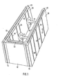
- FIG. 1 The embodiment of a formwork element according to the invention shown in perspective in FIG. 1 has two side walls 10 made of fire-retardant hard foam, which are connected to one another via two webs 11 and an end wall 12.
- the upper and lower edges as well as the front edges of the side walls 10 and the upper and lower edges of the end wall 12 are provided with webs 13 or complementary grooves 14 which are circular in cross section with a short approach are trained.
- To assemble the springs 13 are inserted into the grooves 14.
- Markings in the form of flat channels 16 are arranged on the outside of the side walls 10, which enable a cut to size. Centering points 17 mark the position of the connecting webs 11.
- FIG. 2 shows in more detail an embodiment for the latching point between the side wall 10 and a connecting web 11.
- the side wall has a flat recess 18 with an undercut edge
- the foot 19 of the connecting element 11 has a complementary elevation 20 with a retracted edge, which can be snapped or clipped into the recess 18 by snapping.
- the shape is such that a certain amount of tension remains after clipping in and thus the connecting web 11 is held securely against the wall 10. If you glue the surfaces that are next to each other with adhesive before clipping in, this results in a very secure and tensile connection.
- FIG 3 shows a complementary design of the connection point between the connecting web 11 and the side wall 10.
- the foot 19 contains the flat depression 18 and the wall 10 contains the corresponding elevation 20.
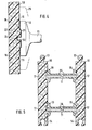
- FIG. 4 Another embodiment for the connection between the side wall 10 and the connecting element 11 is shown in FIG. 4.
- the foot 19 of the connecting web 11 has a flat, central recess 21, and the Wall 10 is equipped with a corresponding elevation 22.
- a ball 23 is arranged in the center of the depression 21 and engages in a ball socket 24 by being pressed into it.
- a residual tension is exerted on the connecting element 11 after it has snapped in, so that a secure fit and good adhesion is achieved.
- the foot 19 of the connecting web 11 can be provided with extensions 25 indicated by dashed lines.
- FIG. 5 shows a cross section through the formwork element according to FIG. 1.
- two connecting elements 11 arranged one above the other are connected to the side walls 10 by latching.
- the connecting elements 11 consist of concrete and have central bores 26 from both sides, which end at a distance of a few centimeters from one another.
- the centering points 17 on the outside of the side walls 10 mark the position of the bores 26, so that later it is possible to drill through the remaining residue between the two bores 26 for the passage of lines or cables or the attachment of fastening and supporting elements.
- a connecting element 31 which has two end plates 27 and connecting wires or rods 28.
- the plates 27 are snapped into a recess 18, similar to the embodiment according to FIG. 2, and additionally glued there.
- the wires 28 are easily welded to the plates 27 made of sheet metal. The crossing of the wires results in a certain suspension effect, which mitigates shocks when filling with concrete.
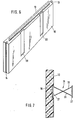
- the side wall 10 shown in perspective is provided with latching points in the form of blind holes 30 with a T-shaped cross section, which are arranged on the upper edge and lower edge.
- the relatively flat blind holes 30 do not significantly weaken the side wall but allow the snap-in connecting webs 41, which are shown in FIG. 9, in a simple manner.
- Each connecting web 41 has an end plate 32 of square shape and a connecting rod 33 with a rectangular cross section.
- the connecting webs 41 are used alternately in the position shown in FIGS. 9a and 9b, that is to say with a rotation of 90 °.
- the blind holes 30 must be adjusted accordingly (not shown) with regard to their connection to the inner surface of the side wall 10.
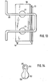
- FIG. 10 shows an exemplary embodiment of a double connecting web 51.
- Two cranked connecting wires 34 each have plates 35 at their ends, which can be designed similarly to the plates 32 in FIG. 9. The plates lie in the blind holes 30 according to FIG. 8.
- the wires 34 are connected to one another in accordance with the schematic illustration, for example by screwing or welding.
- a double connecting element 51 with an X-shape is created, which in turn has a certain spring effect and can thus absorb shocks.
- FIG. 12 shows, in the form of a partial section, the attachment of a side wall 10 used as a thermal insulation panel to a building wall 40 to be insulated.
- the ball socket 24 (cf. FIG. 4) of the panel 10 which in the exemplary embodiment shown does not rise directly in the wall 10 is attached, the ball 23 of a holder 42 engages, a flange 43 laying against the plate 10.
- gluing in the area of Flange 43 and the ball 23 take place.
- a foot 44 which contains a screw 45 with which the holder 42 is screwed into the wall 40 to be insulated, adjoins the flange 43 of the holder 42. The distance between the plate 10 and the wall 40 achieved by the holder 42 results in a desired additional insulation and ventilation.
- FIG. 13 schematically shows the use of a side wall 10 as a floor insulation panel with a hose 46 of an underfloor heating.
- the hose 46 can be positioned exactly at the stop points, which are only shown schematically in the form of, for example, elevations 21 according to FIG. 4, wherein a fastening element according to FIG. 14 can be used.
- the fastening element has a ball 53 similar to the ball 23 in Figure 4.
- a head 54 with a bore 55 for receiving the hose 46 connects to the ball.
- a slot 56 leads through the ball to the bore 55, so that the two halves of the ball 53 can be bent and in this way the hose can be brought into the bore 55.
- the ball 53 is then pressed into a ball socket (not shown) corresponding to the ball socket 24 in FIG. 4.
- FIG. 6 A modification of the side wall 10 is shown in FIG. 6.
- dovetail grooves 58 are provided which start from the upper edge and end in front of the lower edge of the wall 10.
- connecting elements 11 with a correspondingly designed foot can be inserted and glued into the dovetail grooves 58.
- the remaining free parts of the dovetail groove 58 cause the side wall 10 to be additionally fixed to the filled concrete.
- the side walls 10 alternately have grooves 60 on their entire inside, which are at their base are expanded and thus have the shape of a rounded dovetail.
- the webs 61 between adjacent grooves 60 have a cross section that is complementary to the grooves 60.
- the associated connecting webs 11 are expediently made in one piece from concrete. They have plate-shaped end plates 62, the outer surfaces of which have webs 63 which penetrate into the grooves 60 and grooves 64 which receive the webs 61.
- the webs 63 which can be continuous or interrupted, have a rectangular cross section, so that the connecting webs 11 can be inserted into the side walls 10. This can be done practically anywhere and at any height of the formwork elements.
- a very high strength of the connection point between the connecting webs 11 and the side walls 10 can be achieved by using a suitable adhesive.
- An end piece 66 closes off the corner from the outside. 15 on the edges, this end piece has the same grooves 60 and tongues 61 as the side walls 10 and can therefore be pushed into the side walls while achieving a non-positive connection.
- Those facing the inside of the formwork element Grooves and tongues 60, 61 of the connecting piece 66 serve, like the free grooves 60, 61 of the side walls 10, of a resilient padding which dampens the dynamic forces which then occur when the concrete is poured in.
- FIG. 17 shows a T-shaped connection point between formwork elements according to FIG. 15. Again, no special designs are required. It is only necessary to remove part of the .side wall 10 at the joint at 67, so that there is again no risk of fire breakdown. The connecting webs 11 are brought close to the point 67 in order to achieve the required strength or project into this.
- FIG. 18 schematically shows a ceiling closure using formwork elements according to FIG. 15.
- the upper part of the side wall 10 is removed from the uppermost formwork element in accordance with the thickness of the ceiling 68 shown in broken lines at 69 up to the height of the filled-in concrete 70.
- the protruding part of the end plate 62 of the uppermost connecting web 11 can be knocked off, if necessary.
- the connecting web 11 has two circumferential grooves 71 on both sides at the transition into the end plates 62.
- Horizontal and / or vertical reinforcing bars 72 can be inserted into these in a positioned manner.
- an adhesive which contains a solvent for polystyrene in an appropriate dilution, the dilution being selected such that the cell walls of the polystyrene only are dissolved and softened so far that a smoothing of the surface of the polystyrene and adjustment to the surface of the webs is made possible without the cell walls of the polystyrene collapsing.
- This dissolving of the cell walls in the surface area of the rigid foam surprisingly leads to a solidification of the surface of the formwork element, since the rigid foam balls from which the rigid foam is made bake together, so that a welded surface layer of the rigid foam is produced in the area of the adhesive point.
- the adhesive used it is important to use the solvent of the rigid foam in a controlled manner. This generally requires dilution with a filler or the like based on cellulose, acrylic resin or polyester resin. can exist. This filler also has the function of filling any gaps between the formwork element and the webs.
- the consistency of the adhesive can be adapted to the application process, with spraying, brushing and filling.
- glue can be applied to either the web or the rigid foam or to these two parts.
- the adhesive applied to the webs can differ from the adhesive applied to the rigid foam, in particular it can be portions of a two-component adhesive. If both sides of the surfaces to be glued are treated with adhesive, then the consistency of the adhesives for one side, for example the webs, can differ from the consistency of the adhesives on the other side, that is, the rigid foam. For example, one side to be glued is sprayed with an aerosol, while the other side is coated with a paste, which ensures surface leveling between the surfaces to be glued.
- the S chalungssystem for the cladding concrete manner can be supplemented by a further not shown member, whereby in particular horizontal formwork end walls can be formed.
- This element has latching points on its narrow sides which correspond to the corresponding latching points 18, 20, 23, 27, 63, 64 of the webs and thus cooperate with the latching points 18, 20, 24, 30, 58, 60, 61 of the wall formwork elements can.
- These formwork elements provided to form a horizontal formwork end wall have a width which corresponds to the length of the webs, while the length of these elements is not critical and can be, for example, 1 m, since one can form a horizontal formwork end wall from individual pieces.
- these formwork elements expediently have tongue and groove on their small narrow sides, which can have the design according to parts 13, 14. In this way it is possible to put together a continuous, horizontal formwork end wall from individual formwork elements.
- Such a horizontal formwork wall is inserted into the vertically running snap-in points of the narrow sides of the side wall formwork elements 10 and held by
- the advantage is that the horizontal formwork end wall can be moved up or down as far as this corresponds to the height of the window opening or door opening. It is understood that the horizontal formwork end wall is supported in a known manner from below when casting the lintel.
Priority Applications (8)
| Application Number | Priority Date | Filing Date | Title |
|---|---|---|---|
| AT85101553T ATE63150T1 (de) | 1984-02-17 | 1985-02-13 | Schalungselement fuer die mantelbetonbauweise. |
| ZA857089A ZA857089B (en) | 1985-02-13 | 1985-09-16 | Formwork assembly for concrete wall structures |
| HU853502A HUT39820A (en) | 1985-02-13 | 1985-09-17 | Cradling member for concreting |
| IL76720A IL76720A0 (en) | 1985-02-13 | 1985-10-15 | Formwork assembly for concrete walls |
| ES1985296351U ES296351Y (es) | 1985-02-13 | 1985-11-14 | Elemento de encofrado para la construccion de revestimientos de hormigon, en especial de material espumoso duro |
| DE19863601878 DE3601878A1 (de) | 1985-02-13 | 1986-01-23 | Befestigungselement fuer die mantelbetonbauweise |
| EG38/86A EG17624A (en) | 1985-02-13 | 1986-01-27 | Formwork assembly for concrete wall structures |
| BR8600618A BR8600618A (pt) | 1985-02-13 | 1986-02-13 | Elemento de cofragem para a construcao de cimento com revestimento exterior e material adesivo para a ligacao dos filetes ou machos e dos elementos de cofragem consistindo de material de espuma endurecida |
Applications Claiming Priority (2)
| Application Number | Priority Date | Filing Date | Title |
|---|---|---|---|
| DE3405736 | 1984-02-17 | ||
| DE19843405736 DE3405736A1 (de) | 1984-02-17 | 1984-02-17 | Schalungselement fuer die mantelbetonbauweise sowie waermedaemmplatte |
Publications (3)
| Publication Number | Publication Date |
|---|---|
| EP0153660A2 true EP0153660A2 (de) | 1985-09-04 |
| EP0153660A3 EP0153660A3 (en) | 1987-03-25 |
| EP0153660B1 EP0153660B1 (de) | 1991-05-02 |
Family
ID=6228027
Family Applications (1)
| Application Number | Title | Priority Date | Filing Date |
|---|---|---|---|
| EP85101553A Expired - Lifetime EP0153660B1 (de) | 1984-02-17 | 1985-02-13 | Schalungselement für die Mantelbetonbauweise |
Country Status (6)
| Country | Link |
|---|---|
| US (1) | US4655014A (es) |
| EP (1) | EP0153660B1 (es) |
| AT (1) | ATE63150T1 (es) |
| CA (1) | CA1244668A (es) |
| DE (2) | DE3405736A1 (es) |
| PT (1) | PT78996A (es) |
Cited By (18)
| Publication number | Priority date | Publication date | Assignee | Title |
|---|---|---|---|---|
| WO1987004478A1 (en) * | 1986-01-23 | 1987-07-30 | Ipa-Isorast International S.A. | Securing element for cased concrete structures |
| WO1987004484A1 (en) * | 1986-01-21 | 1987-07-30 | Goncalves Francisco Guilherme | Special seal and sealing system for the storage of valuables |
| AT388589B (de) * | 1986-03-24 | 1989-07-25 | Alexander Dipl Ing Dr Maculan | Verfahren zur herstellung eines mantelbetonmauerwerkes |
| FR2710676A1 (fr) * | 1993-09-27 | 1995-04-07 | Lapalud Louis | Elément de coffrage perdu pour mur en béton armé ou non. |
| DE4410333A1 (de) * | 1994-03-25 | 1995-11-30 | Guntram Erbe | Schalungsbauteil und Verfahren zu dessen Herstellung |
| DE29701219U1 (de) * | 1997-01-28 | 1997-03-20 | Ziegelwerk Bellenberg Wiest & | Schallschutzwand |
| FR2740488A1 (fr) * | 1995-10-27 | 1997-04-30 | Stradal Sa | Procede de fabrication de blocs de parement |
| WO1998002627A1 (de) * | 1996-07-11 | 1998-01-22 | Mathias Schulze | Verfahren zur herstellung von schalungselementen für mantelbetonbauweise |
| WO1998006911A1 (de) * | 1996-08-13 | 1998-02-19 | Ubs Uni-Bau-System Gmbh | Schalungselement und wandaufbau mit solchen schalungselementen |
| NL1006452C2 (nl) * | 1997-07-02 | 1999-01-05 | Teunis Jan Hartkamp | Bouwsteen en werkwijze voor het bouwen met een dergelijke bouwsteen. |
| WO2002079584A2 (de) * | 2001-04-02 | 2002-10-10 | Bvb Ag | Kombibaustein für ein schalungssystem und schalungssystem |
| ES2275440A1 (es) * | 2005-11-24 | 2007-06-01 | Storopack España.S.A. | "panel aislante para cubiertas de edificios". |
| WO2007124701A2 (en) * | 2006-04-03 | 2007-11-08 | Forting S.R.O. | Building formwork assembly |
| FR2903438A1 (fr) * | 2006-07-07 | 2008-01-11 | Matfor Soc Par Actions Simplif | Element de cloison |
| EP1705302A3 (de) * | 2005-02-15 | 2008-01-16 | Carmine Franco Valente | Element aus Backsteinmaterial zum Erstellen von vorfabrizierten Tafeln für das Bauwesen |
| WO2013093871A1 (en) * | 2011-12-23 | 2013-06-27 | Cantiere Tri Plok Srl | Monoblock construction component with load bearing structure |
| ITPD20120378A1 (it) * | 2012-12-14 | 2014-06-15 | Gianni Moro | Pannello modulare per realizzare casseri a perdere, particolarmente per la costruzione di pareti in calcestruzzo e sistema di casseri a perdere includente detto pannello |
| DE102015207034A1 (de) * | 2015-04-17 | 2016-10-20 | Adolf Hast | Wandelement und Wandsystem |
Families Citing this family (80)
| Publication number | Priority date | Publication date | Assignee | Title |
|---|---|---|---|---|
| US4730422A (en) * | 1985-11-20 | 1988-03-15 | Young Rubber Company | Insulating non-removable type concrete wall forming structure and device and system for attaching wall coverings thereto |
| US4750308A (en) * | 1987-02-09 | 1988-06-14 | Mckay Harry | Heat resistant, insulated wall construction |
| DE3723341A1 (de) * | 1987-07-15 | 1989-01-26 | Ipa Isorast Int | Verfahren zur herstellung von schalungselementen fuer die mantelbetonbauweise und nach dem verfahren hergestellte elemente |
| US4765109A (en) * | 1987-09-25 | 1988-08-23 | Boeshart Patrick E | Adjustable tie |
| US4866891A (en) * | 1987-11-16 | 1989-09-19 | Young Rubber Company | Permanent non-removable insulating type concrete wall forming structure |
| GB8806099D0 (en) * | 1988-03-15 | 1988-04-13 | Roberts P | Support structure comprising building block |
| US4889310A (en) * | 1988-05-26 | 1989-12-26 | Boeshart Patrick E | Concrete forming system |
| US4938449A (en) * | 1989-02-13 | 1990-07-03 | Boeshart Patrick E | Tie for concrete forms |
| US5123222A (en) * | 1990-06-21 | 1992-06-23 | Reddi Form, Inc. | Plastic forms for poured concrete |
| US5014480A (en) * | 1990-06-21 | 1991-05-14 | Ron Ardes | Plastic forms for poured concrete |
| ES2049565B1 (es) * | 1991-05-17 | 1996-08-01 | Leal Baldomero Ropero | Bloque de construccion ornamental. |
| US5317850A (en) * | 1992-10-07 | 1994-06-07 | Simpson Strong-Tie Company, Inc. | Offset anchor bolt and method of orientation |
| DE9302320U1 (de) * | 1993-02-17 | 1994-06-16 | Gruber Eva M | Wandelement, insbesondere Doppelwandelement |
| US5390459A (en) * | 1993-03-31 | 1995-02-21 | Aab Building System Inc. | Concrete form walls |
| US5459971A (en) * | 1994-03-04 | 1995-10-24 | Sparkman; Alan | Connecting member for concrete form |
| US5497592A (en) * | 1994-05-19 | 1996-03-12 | Boeshart; Patrick E. | Quick release tie |
| US5657600A (en) * | 1994-06-20 | 1997-08-19 | Aab Building Systems Inc. | Web member for concrete form walls |
| US5787668A (en) * | 1996-03-11 | 1998-08-04 | Siplast, Inc. | Ventilated insulated roofing system with improved resistance to wind uplift |
| US5887401A (en) * | 1997-07-24 | 1999-03-30 | Eco-Block Llc | Concrete form system |
| US6481178B2 (en) | 1998-01-16 | 2002-11-19 | Eco-Block, Llc | Tilt-up wall |
| US6609340B2 (en) | 1998-01-16 | 2003-08-26 | Eco-Block, Llc | Concrete structures and methods of forming the same using extenders |
| US6170220B1 (en) | 1998-01-16 | 2001-01-09 | James Daniel Moore, Jr. | Insulated concrete form |
| CA2251310C (en) * | 1998-10-19 | 2002-04-02 | John Rice | Bracket for concrete forms |
| US6314697B1 (en) | 1998-10-26 | 2001-11-13 | James D. Moore, Jr. | Concrete form system connector link and method |
| US6336301B1 (en) | 1998-11-05 | 2002-01-08 | James D. Moore, Jr. | Concrete form system ledge assembly and method |
| EP1036891B1 (de) * | 1999-03-01 | 2005-11-09 | Gabriele Raschke | Vorgefertigtes Verbundsystem zur Herstellung von Innen- und/oder Aussenwänden von Gebäuden |
| AU2953399A (en) * | 1999-03-30 | 2000-10-16 | Aab Building Systems, Inc. | Bridging member for concrete form walls |
| US6352237B1 (en) | 1999-08-05 | 2002-03-05 | Charles J. Severino | Insulated concrete forming system |
| US6308484B1 (en) | 1999-08-05 | 2001-10-30 | Thermalite, Inc. | Insulated concrete forming system |
| US20060059846A1 (en) * | 1999-10-19 | 2006-03-23 | John Rice | Bracket for concrete forms |
| US6318040B1 (en) | 1999-10-25 | 2001-11-20 | James D. Moore, Jr. | Concrete form system and method |
| US6698710B1 (en) | 2000-12-20 | 2004-03-02 | Portland Cement Association | System for the construction of insulated concrete structures using vertical planks and tie rails |
| US7337591B2 (en) * | 2001-11-28 | 2008-03-04 | Inteplast Group, Ltd. | Building construction system |
| GB0222661D0 (en) * | 2002-10-01 | 2002-11-06 | Buntain Christopher C M | Insulated building component |
| US6915613B2 (en) * | 2002-12-02 | 2005-07-12 | Cellox Llc | Collapsible concrete forms |
| ATE365840T1 (de) * | 2003-02-15 | 2007-07-15 | Heraklith Ag | Verlorener schalungsk rper |
| CZ20032141A3 (cs) | 2003-08-06 | 2005-05-18 | Canstroy Cz, S. R. O. | Systém izolačního bednění pro betonovou stěnu a kloubově uložené rozpěrné spojovací žebro |
| DE202004007959U1 (de) | 2004-05-14 | 2005-09-22 | Krecke, Edmond D. | Wandelement mit Lehm- oder Tonschicht |
| US7861479B2 (en) | 2005-01-14 | 2011-01-04 | Airlite Plastics, Co. | Insulated foam panel forms |
| US20070012857A1 (en) * | 2005-07-13 | 2007-01-18 | Mccarthy Todd | Pilaster form for an insulating concrete form building system |
| DE102005062156A1 (de) * | 2005-12-22 | 2007-06-28 | Bvb Ag | Schalungselement |
| US7818925B2 (en) * | 2006-06-12 | 2010-10-26 | Bryan Benedict | Stay-in-place concrete footing forms |
| CA2658365A1 (en) * | 2006-07-21 | 2008-01-24 | Phil-Insul Corporation | Insulated concrete form panel reinforcement |
| EP2118393A4 (en) * | 2007-02-02 | 2015-11-04 | Matériaux De Construction Oldcastle Canada Inc | WALL WITH DECORATIVE DECORATIVE |
| US9206599B2 (en) | 2007-02-02 | 2015-12-08 | Les Materiaux De Construction Oldcastle Canada, Inc. | Wall with decorative facing |
| GB2450934B (en) * | 2007-07-13 | 2009-10-07 | Rolls Royce Plc | A Component with a damping filler |
| GB2450935B (en) * | 2007-07-13 | 2009-06-03 | Rolls Royce Plc | Component with internal damping |
| GB2458317B (en) * | 2008-03-14 | 2011-01-12 | Herman Funke | Improvements in or relating to ties |
| CN101302780B (zh) * | 2008-03-14 | 2010-11-10 | 邹用军 | 建筑隔墙用轻质条板 |
| US20090250560A1 (en) * | 2008-04-07 | 2009-10-08 | Shui-Fang Chou | Utility Tray Module for Power Plant Construction |
| US20090273117A1 (en) * | 2008-04-30 | 2009-11-05 | Sowder Joseph T | Guiding apparatus |
| GB0808840D0 (en) | 2008-05-15 | 2008-06-18 | Rolls Royce Plc | A compound structure |
| GB2462102B (en) * | 2008-07-24 | 2010-06-16 | Rolls Royce Plc | An aerofoil sub-assembly, an aerofoil and a method of making an aerofoil |
| US9238910B2 (en) * | 2008-08-19 | 2016-01-19 | David I. Jensen | Interlocking wall unit system for constructing a wall on a pre-existing structural grid matrix |
| US9091055B2 (en) | 2008-08-19 | 2015-07-28 | Sonoma Cast Stone Corporation | Wall assembly method |
| GB0901235D0 (en) * | 2009-01-27 | 2009-03-11 | Rolls Royce Plc | An article with a filler |
| GB0901318D0 (en) * | 2009-01-28 | 2009-03-11 | Rolls Royce Plc | A method of joining plates of material to form a structure |
| GB0909280D0 (en) | 2009-06-01 | 2009-07-15 | Ciba Holding Inc | Wall form system |
| FR2949483B1 (fr) * | 2009-09-01 | 2013-11-08 | Charles Cebador | Mur de batiment et procede pour realiser ce mur |
| GB201009216D0 (en) | 2010-06-02 | 2010-07-21 | Rolls Royce Plc | Rotationally balancing a rotating part |
| US9732519B1 (en) * | 2010-06-28 | 2017-08-15 | John J Venturo | Stackable building block with vertical center risers |
| CA2806259C (en) * | 2010-09-28 | 2014-04-22 | Les Materiaux De Construction Oldcastle Canada, Inc. | Retaining wall |
| US9670640B2 (en) * | 2010-09-28 | 2017-06-06 | Les Materiaux De Construction Oldcastle Canada, Inc. | Retaining wall |
| US9441342B2 (en) * | 2010-09-28 | 2016-09-13 | Les Materiaux De Construction Oldcastle Canada, In | Retaining wall |
| GB2485831B (en) | 2010-11-26 | 2012-11-21 | Rolls Royce Plc | A method of manufacturing a component |
| AU2012231761A1 (en) | 2011-03-18 | 2013-10-03 | Peter Mervyn NEIL | Composite wall panel, wall system and components thereof, and a method of construction thereof |
| US8919067B2 (en) | 2011-10-31 | 2014-12-30 | Airlite Plastics Co. | Apparatus and method for construction of structures utilizing insulated concrete forms |
| CA2801735C (en) | 2012-01-13 | 2019-08-06 | Bradley J. Crosby | An apparatus and method for construction of structures utilizing insulated concrete forms |
| US8635826B2 (en) * | 2012-04-10 | 2014-01-28 | Reward Wall Systems, Inc. | Insulation insert panel for use with insulating concrete form (ICF) systems |
| USD713975S1 (en) | 2012-07-30 | 2014-09-23 | Airlite Plastics Co. | Insulative insert for insulated concrete form |
| CA2901433C (en) | 2013-02-25 | 2020-09-01 | Les Materiaux De Construction Oldcastle Canada Inc. | Wall assembly |
| ES2569152B1 (es) * | 2014-05-07 | 2017-01-10 | Indepool, S.L. | Conjunto de dispositivos para la construcción de piscinas y procedimiento de construcción correspondiente |
| CL2014002766A1 (es) * | 2014-10-15 | 2014-12-19 | Cisternas Jessica Andrea Mora | Elemento de polietileno expandido para utilizar en la construcción, comprende una placa paralelepípedo delgada para rematar y cerrar herméticamente elementos de moldaje para confeccionar muros de hormigón armado integrando aislación acústica y térmica, por medio de un sistema de unión machihembrado. |
| ITUB20160199A1 (it) * | 2016-01-14 | 2017-07-14 | Flex House Srl | Elemento distanziatore per cassero a perdere per la realizzazione di pareti e cassero a perdere incorporante tale elemento distanziatore |
| CA2985438A1 (en) | 2016-11-14 | 2018-05-14 | Airlite Plastics Co. | Concrete form with removable sidewall |
| CN107761735A (zh) * | 2017-11-10 | 2018-03-06 | 中国水利水电第十四工程局有限公司 | 一种混凝土表面分隔、装饰线条施工方法 |
| CA3056094A1 (en) | 2018-09-21 | 2020-03-21 | Cooper E. Stewart | Insulating concrete form apparatus |
| CA3061942A1 (en) | 2018-11-19 | 2020-05-19 | Bradley J. Crosby | Concrete form with removable sidewall |
| US11718985B2 (en) * | 2020-10-14 | 2023-08-08 | Isaac Walker | Construction block |
| US20220195732A1 (en) * | 2020-12-22 | 2022-06-23 | Mark WAAGE | Variable spacer system of insulated concrete forms |
Citations (12)
| Publication number | Priority date | Publication date | Assignee | Title |
|---|---|---|---|---|
| US2181698A (en) * | 1938-09-29 | 1939-11-28 | Frederick G Langenberg | Wall construction |
| DE1241589B (de) * | 1963-11-26 | 1967-06-01 | Karl Schwaerzler Dipl Ing | Schalungselement zum Herstellen von Waenden in der Mantelbetonbauweise |
| DE1243368B (de) * | 1963-12-02 | 1967-06-29 | Gert Gandert Dipl Ing | Zweiteiliges Schalungselement fuer die Mantelbetonbauweise |
| CH461063A (de) * | 1966-11-25 | 1968-08-15 | Raber Otto | Bauelement |
| AT278303B (de) * | 1965-04-09 | 1970-01-26 | Othmar Wiegand | Abstandshalter für Schalungsplatten |
| DE7131525U (de) * | 1971-12-09 | Luetkenhaus B | Mehrteiliges Plattenelement für Fertighaus-Konstruktionen | |
| DE7120078U (de) * | 1973-03-15 | Kissel P | Schalungselement von Mantelbetonwänden | |
| DE7335733U (de) * | 1974-03-07 | Isopor Kunststoff Gmbh | Schalungsplatte aus Hartschaum- oder Hartkunststoff | |
| DE2328098A1 (de) * | 1973-06-01 | 1974-12-19 | Cotarex Ets | Verlorene schalung fuer eine mantelbetonwand |
| DE7625460U1 (de) * | 1976-08-13 | 1980-03-13 | Hering, Peter, 6229 Erbach | Fertigbauelement |
| EP0092693A1 (de) * | 1982-04-23 | 1983-11-02 | Aregger AG Bauunternehmung | Schalungselement mit Hartschaum-Platten für die Mantelbetonbauweise |
| DE8326241U1 (de) * | 1983-07-19 | 1984-02-09 | Gonon, Eugen Christoph, 8226 Schleitheim | Baustein |
Family Cites Families (13)
| Publication number | Priority date | Publication date | Assignee | Title |
|---|---|---|---|---|
| US929969A (en) * | 1908-09-02 | 1909-08-03 | Patrick O Gara | Permanent concrete form. |
| GB137221A (en) * | 1919-05-09 | 1920-01-08 | James Hardress Connelly | An improved tie for use in reinforced concrete work |
| FR730009A (fr) * | 1931-04-03 | 1932-08-05 | Procédé de construction en bétons armés et coffrages revêtements réalisant ledit procédé | |
| US2185335A (en) * | 1937-04-05 | 1940-01-02 | Albert C Fischer | Structural member |
| FR857507A (fr) * | 1939-07-08 | 1940-09-17 | Briques tubulaires à ancrages pour maçonnerie de bâtiments | |
| CH289601A (fr) * | 1950-06-27 | 1953-03-31 | Beaupere Hubert Henri | Mur en éléments moulés. |
| FR1299616A (fr) * | 1961-06-12 | 1962-07-27 | Profilés pour bardage, leur fabrication, leur dispositif d'accrochage et leur mise en oeuvre | |
| US3233380A (en) * | 1962-03-09 | 1966-02-08 | Morton M Rosenfeld | Wall structure and block therefor |
| US3255562A (en) * | 1963-03-08 | 1966-06-14 | Robert L Altschuler | Plastic wall forming blocks and spline connectors therefor |
| AT245208B (de) * | 1963-05-08 | 1966-02-25 | Otto Urlepp | Verlorene Schalung zur Herstellung von Mauerwerk in Schüttbauweise |
| DE1299839B (de) * | 1963-09-27 | 1969-07-24 | Alpine Iso Span Gmbh | Schalungselement |
| US3562988A (en) * | 1969-06-24 | 1971-02-16 | Lock Block Co Z | Building blocks, bricks, tile, panels and the like |
| US4234156A (en) * | 1979-04-24 | 1980-11-18 | Acrow-Richmond Limited | Snap-tie |
-
1984
- 1984-02-17 DE DE19843405736 patent/DE3405736A1/de not_active Withdrawn
- 1984-07-30 PT PT78996A patent/PT78996A/pt not_active IP Right Cessation
-
1985
- 1985-02-13 DE DE8585101553T patent/DE3582685D1/de not_active Expired - Fee Related
- 1985-02-13 AT AT85101553T patent/ATE63150T1/de not_active IP Right Cessation
- 1985-02-13 EP EP85101553A patent/EP0153660B1/de not_active Expired - Lifetime
- 1985-02-15 US US06/702,040 patent/US4655014A/en not_active Expired - Fee Related
- 1985-02-15 CA CA000474418A patent/CA1244668A/en not_active Expired
Patent Citations (12)
| Publication number | Priority date | Publication date | Assignee | Title |
|---|---|---|---|---|
| DE7131525U (de) * | 1971-12-09 | Luetkenhaus B | Mehrteiliges Plattenelement für Fertighaus-Konstruktionen | |
| DE7120078U (de) * | 1973-03-15 | Kissel P | Schalungselement von Mantelbetonwänden | |
| DE7335733U (de) * | 1974-03-07 | Isopor Kunststoff Gmbh | Schalungsplatte aus Hartschaum- oder Hartkunststoff | |
| US2181698A (en) * | 1938-09-29 | 1939-11-28 | Frederick G Langenberg | Wall construction |
| DE1241589B (de) * | 1963-11-26 | 1967-06-01 | Karl Schwaerzler Dipl Ing | Schalungselement zum Herstellen von Waenden in der Mantelbetonbauweise |
| DE1243368B (de) * | 1963-12-02 | 1967-06-29 | Gert Gandert Dipl Ing | Zweiteiliges Schalungselement fuer die Mantelbetonbauweise |
| AT278303B (de) * | 1965-04-09 | 1970-01-26 | Othmar Wiegand | Abstandshalter für Schalungsplatten |
| CH461063A (de) * | 1966-11-25 | 1968-08-15 | Raber Otto | Bauelement |
| DE2328098A1 (de) * | 1973-06-01 | 1974-12-19 | Cotarex Ets | Verlorene schalung fuer eine mantelbetonwand |
| DE7625460U1 (de) * | 1976-08-13 | 1980-03-13 | Hering, Peter, 6229 Erbach | Fertigbauelement |
| EP0092693A1 (de) * | 1982-04-23 | 1983-11-02 | Aregger AG Bauunternehmung | Schalungselement mit Hartschaum-Platten für die Mantelbetonbauweise |
| DE8326241U1 (de) * | 1983-07-19 | 1984-02-09 | Gonon, Eugen Christoph, 8226 Schleitheim | Baustein |
Cited By (24)
| Publication number | Priority date | Publication date | Assignee | Title |
|---|---|---|---|---|
| WO1987004484A1 (en) * | 1986-01-21 | 1987-07-30 | Goncalves Francisco Guilherme | Special seal and sealing system for the storage of valuables |
| WO1987004478A1 (en) * | 1986-01-23 | 1987-07-30 | Ipa-Isorast International S.A. | Securing element for cased concrete structures |
| EP0235843A1 (de) * | 1986-01-23 | 1987-09-09 | Ipa-Isorast International S.A. | Befestigungselement für die Mantelbetonbauweise |
| US4949515A (en) * | 1986-01-23 | 1990-08-21 | Krecke Edmond D | Fastening element for the cladding concrete method of construction |
| AT388589B (de) * | 1986-03-24 | 1989-07-25 | Alexander Dipl Ing Dr Maculan | Verfahren zur herstellung eines mantelbetonmauerwerkes |
| FR2710676A1 (fr) * | 1993-09-27 | 1995-04-07 | Lapalud Louis | Elément de coffrage perdu pour mur en béton armé ou non. |
| DE4410333A1 (de) * | 1994-03-25 | 1995-11-30 | Guntram Erbe | Schalungsbauteil und Verfahren zu dessen Herstellung |
| FR2740488A1 (fr) * | 1995-10-27 | 1997-04-30 | Stradal Sa | Procede de fabrication de blocs de parement |
| WO1998002627A1 (de) * | 1996-07-11 | 1998-01-22 | Mathias Schulze | Verfahren zur herstellung von schalungselementen für mantelbetonbauweise |
| WO1998006911A1 (de) * | 1996-08-13 | 1998-02-19 | Ubs Uni-Bau-System Gmbh | Schalungselement und wandaufbau mit solchen schalungselementen |
| DE29701219U1 (de) * | 1997-01-28 | 1997-03-20 | Ziegelwerk Bellenberg Wiest & | Schallschutzwand |
| WO1999001625A1 (en) * | 1997-07-02 | 1999-01-14 | Teunis Jan Hartkamp | Building brick and method for building with a building brick of this nature |
| NL1006452C2 (nl) * | 1997-07-02 | 1999-01-05 | Teunis Jan Hartkamp | Bouwsteen en werkwijze voor het bouwen met een dergelijke bouwsteen. |
| WO2002079584A2 (de) * | 2001-04-02 | 2002-10-10 | Bvb Ag | Kombibaustein für ein schalungssystem und schalungssystem |
| WO2002079584A3 (de) * | 2001-04-02 | 2003-02-20 | Bvb Ag | Kombibaustein für ein schalungssystem und schalungssystem |
| EP1705302A3 (de) * | 2005-02-15 | 2008-01-16 | Carmine Franco Valente | Element aus Backsteinmaterial zum Erstellen von vorfabrizierten Tafeln für das Bauwesen |
| ES2275440A1 (es) * | 2005-11-24 | 2007-06-01 | Storopack España.S.A. | "panel aislante para cubiertas de edificios". |
| WO2007124701A2 (en) * | 2006-04-03 | 2007-11-08 | Forting S.R.O. | Building formwork assembly |
| WO2007124701A3 (en) * | 2006-04-03 | 2008-01-03 | Forting S R O | Building formwork assembly |
| FR2903438A1 (fr) * | 2006-07-07 | 2008-01-11 | Matfor Soc Par Actions Simplif | Element de cloison |
| WO2013093871A1 (en) * | 2011-12-23 | 2013-06-27 | Cantiere Tri Plok Srl | Monoblock construction component with load bearing structure |
| ITPD20120378A1 (it) * | 2012-12-14 | 2014-06-15 | Gianni Moro | Pannello modulare per realizzare casseri a perdere, particolarmente per la costruzione di pareti in calcestruzzo e sistema di casseri a perdere includente detto pannello |
| WO2014091377A1 (en) * | 2012-12-14 | 2014-06-19 | Moro Gianni | A modular panel for producing disposable formwork, in particular for the construction of concrete walls, and a disposable formwork system including said panel |
| DE102015207034A1 (de) * | 2015-04-17 | 2016-10-20 | Adolf Hast | Wandelement und Wandsystem |
Also Published As
| Publication number | Publication date |
|---|---|
| US4655014A (en) | 1987-04-07 |
| CA1244668A (en) | 1988-11-15 |
| DE3582685D1 (de) | 1991-06-06 |
| ATE63150T1 (de) | 1991-05-15 |
| EP0153660B1 (de) | 1991-05-02 |
| PT78996A (de) | 1984-08-01 |
| EP0153660A3 (en) | 1987-03-25 |
| DE3405736A1 (de) | 1985-08-22 |
Similar Documents
| Publication | Publication Date | Title |
|---|---|---|
| EP0153660A2 (de) | Schalungselement für die Mantelbetonbauweise | |
| EP0034332A2 (de) | Bauelement zur Wärmedämmung bei Gebäuden | |
| AT410567B (de) | Deckenrandschalenelement sowie verwendung desselben | |
| DE19758238A1 (de) | Schalungssystem | |
| EP2960392A1 (de) | Deckenrandschalungselement | |
| WO1982002732A1 (en) | Construction element | |
| DE3212245C2 (de) | Verfahren zur Herstellung eines wärmeisolierenden Bauelementes | |
| AT520407A1 (de) | Schalungselement | |
| EP0083438B1 (de) | Schalungselement aus geschäumtem Hartkunststoff für die Mantelbetonbauweise | |
| DE102017114619B4 (de) | System aus zumindest zwei Transporthaken und einem vorgefertigten Wandelement und Verfahren zur Herstellung eines vorgefertigten Wandelements | |
| DE3214502A1 (de) | Plattenfoermiges bauelement fuer die mantelbetonbauweise | |
| EP1592852A1 (de) | Verlorener schalungsk rper | |
| DE202014102920U1 (de) | Deckenrandschalungselement | |
| EP0775784A1 (de) | Wärmedämmende Wand, Verfahren zum Erstellen einer wärmedämmenden Wand und Wärmedämmblock | |
| DE858304C (de) | Bauplatte zur Herstellung von Waenden und Decken | |
| DE19949278A1 (de) | Verfahren zur Herstellung der Außenwände eines Massivhauses und Verbundschalung | |
| DE10046138C2 (de) | Fertigmodul für Gebäudeetagen eines Hauses und Verfahren zur Herstellung und Aufbau von Gebäudeteilen aus Fertigmodulen | |
| DE3340648A1 (de) | Bauelement fuer die mantelbetonbauweise | |
| DE2925354A1 (de) | Haus aus tragenden stahlbetonfertigteilen | |
| DE2804637A1 (de) | Vorgefertigtes bauteil zur verwendung im bauwesen | |
| EP0707119B1 (de) | System zur Halterung und Befestigung | |
| EP1647644A2 (de) | Raumzelle zum Einbau in einen Raum eines Bauwerks | |
| DE802655C (de) | Pfostenstein mit seitlichen Fuehrungen zur Bildung von Pfosten zum Anschluss von Plattenwaenden | |
| EP1203846A1 (de) | Wärmedämmverbundsystem sowie Dämmstoffelemente und Herstellungsverfahren dafür | |
| WO2023062483A1 (de) | Konstruktionssystem |
Legal Events
| Date | Code | Title | Description |
|---|---|---|---|
| PUAI | Public reference made under article 153(3) epc to a published international application that has entered the european phase |
Free format text: ORIGINAL CODE: 0009012 |
|
| AK | Designated contracting states |
Designated state(s): AT BE CH DE FR GB IT LI LU NL SE |
|
| PUAL | Search report despatched |
Free format text: ORIGINAL CODE: 0009013 |
|
| AK | Designated contracting states |
Kind code of ref document: A3 Designated state(s): AT BE CH DE FR GB IT LI LU NL SE |
|
| 17P | Request for examination filed |
Effective date: 19870505 |
|
| 17Q | First examination report despatched |
Effective date: 19881118 |
|
| ITF | It: translation for a ep patent filed |
Owner name: DE DOMINICIS & MAYER S.R.L. |
|
| GRAA | (expected) grant |
Free format text: ORIGINAL CODE: 0009210 |
|
| AK | Designated contracting states |
Kind code of ref document: B1 Designated state(s): AT BE CH DE FR GB IT LI LU NL SE |
|
| REF | Corresponds to: |
Ref document number: 63150 Country of ref document: AT Date of ref document: 19910515 Kind code of ref document: T |
|
| GBT | Gb: translation of ep patent filed (gb section 77(6)(a)/1977) | ||
| REF | Corresponds to: |
Ref document number: 3582685 Country of ref document: DE Date of ref document: 19910606 |
|
| ET | Fr: translation filed | ||
| PG25 | Lapsed in a contracting state [announced via postgrant information from national office to epo] |
Ref country code: GB Effective date: 19920213 Ref country code: AT Effective date: 19920213 |
|
| PG25 | Lapsed in a contracting state [announced via postgrant information from national office to epo] |
Ref country code: SE Effective date: 19920214 |
|
| PG25 | Lapsed in a contracting state [announced via postgrant information from national office to epo] |
Ref country code: BE Effective date: 19920228 |
|
| PG25 | Lapsed in a contracting state [announced via postgrant information from national office to epo] |
Ref country code: LU Free format text: LAPSE BECAUSE OF NON-PAYMENT OF DUE FEES Effective date: 19920229 Ref country code: LI Effective date: 19920229 Ref country code: CH Effective date: 19920229 |
|
| PLBE | No opposition filed within time limit |
Free format text: ORIGINAL CODE: 0009261 |
|
| STAA | Information on the status of an ep patent application or granted ep patent |
Free format text: STATUS: NO OPPOSITION FILED WITHIN TIME LIMIT |
|
| 26N | No opposition filed | ||
| BERE | Be: lapsed |
Owner name: S.A. IPA-ISORAST INTERNATIONAL Effective date: 19920228 |
|
| PG25 | Lapsed in a contracting state [announced via postgrant information from national office to epo] |
Ref country code: NL Effective date: 19920901 |
|
| GBPC | Gb: european patent ceased through non-payment of renewal fee | ||
| NLV4 | Nl: lapsed or anulled due to non-payment of the annual fee | ||
| PG25 | Lapsed in a contracting state [announced via postgrant information from national office to epo] |
Ref country code: FR Effective date: 19921030 |
|
| REG | Reference to a national code |
Ref country code: CH Ref legal event code: PL |
|
| PG25 | Lapsed in a contracting state [announced via postgrant information from national office to epo] |
Ref country code: DE Effective date: 19921103 |
|
| REG | Reference to a national code |
Ref country code: FR Ref legal event code: ST |
|
| EUG | Se: european patent has lapsed |
Ref document number: 85101553.7 Effective date: 19920904 |