EP0153847A2 - Intravascular laser catheter - Google Patents
Intravascular laser catheter Download PDFInfo
- Publication number
- EP0153847A2 EP0153847A2 EP85301123A EP85301123A EP0153847A2 EP 0153847 A2 EP0153847 A2 EP 0153847A2 EP 85301123 A EP85301123 A EP 85301123A EP 85301123 A EP85301123 A EP 85301123A EP 0153847 A2 EP0153847 A2 EP 0153847A2
- Authority
- EP
- European Patent Office
- Prior art keywords
- fibres
- catheter
- laser energy
- proximal
- leg
- Prior art date
- Legal status (The legal status is an assumption and is not a legal conclusion. Google has not performed a legal analysis and makes no representation as to the accuracy of the status listed.)
- Granted
Links
Images
Classifications
-
- A—HUMAN NECESSITIES
- A61—MEDICAL OR VETERINARY SCIENCE; HYGIENE
- A61B—DIAGNOSIS; SURGERY; IDENTIFICATION
- A61B18/00—Surgical instruments, devices or methods for transferring non-mechanical forms of energy to or from the body
- A61B18/18—Surgical instruments, devices or methods for transferring non-mechanical forms of energy to or from the body by applying electromagnetic radiation, e.g. microwaves
- A61B18/20—Surgical instruments, devices or methods for transferring non-mechanical forms of energy to or from the body by applying electromagnetic radiation, e.g. microwaves using laser
- A61B18/22—Surgical instruments, devices or methods for transferring non-mechanical forms of energy to or from the body by applying electromagnetic radiation, e.g. microwaves using laser the beam being directed along or through a flexible conduit, e.g. an optical fibre; Couplings or hand-pieces therefor
- A61B18/24—Surgical instruments, devices or methods for transferring non-mechanical forms of energy to or from the body by applying electromagnetic radiation, e.g. microwaves using laser the beam being directed along or through a flexible conduit, e.g. an optical fibre; Couplings or hand-pieces therefor with a catheter
- A61B18/245—Surgical instruments, devices or methods for transferring non-mechanical forms of energy to or from the body by applying electromagnetic radiation, e.g. microwaves using laser the beam being directed along or through a flexible conduit, e.g. an optical fibre; Couplings or hand-pieces therefor with a catheter for removing obstructions in blood vessels or calculi
-
- A—HUMAN NECESSITIES
- A61—MEDICAL OR VETERINARY SCIENCE; HYGIENE
- A61B—DIAGNOSIS; SURGERY; IDENTIFICATION
- A61B90/00—Instruments, implements or accessories specially adapted for surgery or diagnosis and not covered by any of the groups A61B1/00 - A61B50/00, e.g. for luxation treatment or for protecting wound edges
- A61B90/39—Markers, e.g. radio-opaque or breast lesions markers
Abstract
Description
- The present invention relates to apparatus for directing laser energy to vascular obstructions. More particularly it relates to apparatus for directing laser energy through an intravascular catheter to a fixed focal point in order to dissolve an occlusion in a blood vessel.
- Current methods used to remove vascular obstructions such as fatty deposits, plaque, calcification, and emboletic clots in occluded vessels include drug treatment using lysing agents, resection of the occluded vessel, displacement with embolectomy catheters, and balloon angioplasty. In using the embolectomy catheter, the clot must be located and isolated and then surrounded and removed. Balloon angioplasty increases the diameter of an occluded vessel by inflating a balloon and applying pressure stepwise to the sides of the occlusion. This technique is not useful when the vessel is completely occluded. There remains a need for an efficient device to destroy such lesions in situ without adverse side effects, even in completely occluded vessels.
- U.S. Patent No. 4,207,874 discloses a fibre- optic device with a coned head configuration at the distal end thereof. This configuration utilises the coned head to bend the direction of the laser beam, thereby concentrating it near the distal end of the device.
- The present invention seeks to provide apparatus capable of directing laser energy to vascular obstructions in a controlled manner in order to dissolve and remove them.
- According to the invention there is provided apparatus for directing laser energy at a fixed focal point in the body of a patient, said apparatus comprising a catheter having proximal and distal ends and at least one lumen therethrough, a bundle of solid optical fibres in an annular array about the outer wall of said catheter, said fibres having proximal and distal ends and being adapted at their proximal ends for association with an energy source to supply laser energy for transmission to the body of the patient, the distal end of said fibre bundle being bevelled at such an angle as to substantially focus said laser energy at a single focal point.
- The optical fibres may be, for example, fused silica, quartz or glass, and preferably the fibre bundle is enclosed in an outer annular sheath. In a preferred embodiment of the invention, the annular sheath is bifurcated in the vicinity of the proximal end forming a first leg which is adapted to receive the fibres, and a second leg enclosing the catheter. The first leg may be provided with means for association with an energy source, while the second leg terminates in an injection port provided with means for injecting contrast media or a therapeutic fluid through the lumen, or is provided with means for insertion of a guide wire through the lumen.
- As used herein, the term "to reduce a vascular obstruction", or the like, means to substantially reduce the size of the lesion. Preferably, of course, treatment is continued until essentially complete removal of the lesion has been achieved.
- In order that the invention may be better understood, an embodiment thereof will now be described by way of example only and with reference to the accompanying drawings in which:-
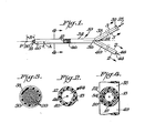
- Figure 1 is a side elevational view of an embodiment of a laser catheter according to the present invention;
- Figure 2 is a cross-sectional view along the line 2-2 of Figure 1;
- Figure 3 is a cross-sectional view along the line 3-3 of Figure 1; and
- Figure 4 is a cross-sectional view along the line 4-4 of Figure 1.
- In Figures 1 to 4 is depicted an
apparatus 10 for directing laser energy to a fixed focal point in an occluded blood vessel, thereby dissolving and removing the occlusion.Apparatus 10 includescatheter 12 having proximal anddistal ends 14,16 respectively, and having a lumen l8 passing therethrough. A bundle of solidoptical fibres 20, each having a core and a clad of different refractive indices, is arranged in an annular array around theouter wall 22 of thecatheter 12.Fibres 20 are adapted at their proximal end for association with alaser energy source 28 through acoupling 30. Theoptical fibres 20 may be glass or quartz, but are preferably fused silica. - The diameter of the
optical fibres 20 is generally between about 0.001 inches and 0.050 inches, preferably .001 inches to .020 inches. The length of thefibres 20 is generally about 50 to 300 cm., preferably 100 to 150 cm. The number of fibres in the bundle, which is arranged in annular array around theouter wall 22, is typically between about 35 and 100, preferably 50 to 75. - In a preferred embodiment,
apparatus 10 is provided with an outerannular sheath 34, preferably made from a flexible material, especially silicone rubber tubing, enclosingfibre bundle 20.Sheath 34 is bifurcated at 36 in the vicinity of the proximal end thereof, forming afirst leg 38 through which are fedfibres 20 which transmit laser energy fromsource 28 to distalend 40 of the fibre bundle. Sheath 34 at bif- u.rcation 36 also extends tosecond leg 42 enclosingcatheter 12.Second leg 42 ofsheath 34 terminates in aninjection port 44 for insertion ofguide wire 46 throughlumen 18. The guide wire is typically radiopaque. Alternatively,injection port 44 may be provided with reservoir containing contrast medium or therapeutic fluid for injection throughlumen 18. The therapeutic fluid may be, for example, saline to rinse the vessel, thrombogentic agents to dissolve clots, or vasodilators to enlarge the vessel. - In accordance with the present invention,
fibre bundle 20 is bevelled at an angle at thedistal end 40 so as to substantially focus laser energy transmitted fromsource 28 to focal point P. Bevelling of thefibre bundle 20 may be achieved by rotating the distal end about its axis while the leading edge is pressed against a rotating disk. The rotating disk material is such that thefibre bundle 20 is both abraded and polished simultaneously. - The angle A of the bevel of the
fibre bundle 20 is selected such that it focuses the laser at a focal point P. The focal length B is related to the angle A of the bevel by the following formula:-
- N2 = index of refraction of the optical fibre clad
- N1 = index of refraction of the optical fibre core
- a = radius of the annular array of fibres from catheter axis to centre of fibre
- α = bevel angle A
- B = focal length
- The catheter diameter and materials of construction of the optical fibres are factors in the relationship between the bevel angle and focal length.
- Thus, for example, when N2 is 1.402, N1 is 1.492 (as for a typical quartz fibre) and a is .035 inches, the focal length depends on the bevel angle as shown in the following table:-

- Accordingly, when a, N1 and N 2 are given, a desired focal length can be obtained by appropriate selection of the corresponding bevel angle. For the reduction of vascular obstructions, a focal length of from about .100 in. to about .200 in. is preferred.
- In use, the occlusion is located by angiography, or percutaneous puncture. The laser catheter is then advanced through an arteriotomy up to the occlusion. In peripheral arteries contrast media is injected through the catheter to locate the occlusion with a fluoroscope. With the distal tip of the annular array of fibres spaced from the occlusion by the fixed focal length of the device, the laser is then fired to destroy the occlusion. With coronary arteries the contrast media is injected through the catheter to locate the coronary arterial tree. A guide wire is threaded through the catheter into the selected arterial segment, until it comes into contact with the occlusion, the radiopaque nature of the guide wire facilitating the detection of position of the occlusion by fluor- oscopy.
- The catheter is then threaded over the guide wire to a position proximal to the distal tip of the guide wire, which is substantially equal to the focal length B of the catheter as determined by the bevelled angle A.
- The fixed focal point laser catheter of the present invention eliminates many of the problems of previously used methods for removal of vascular obstructions, and provides a disposable, relatively simple system, which substantially focuses the laser energy at a single fixed, preset point, thereby eliminating the risk of accidental perforation of the vessel. The novel device of this invention has the further advantage of being effective even in a completely occluded vessel. In addition, it is of relatively uncomplicated design, offers easy manipulation and insertion, and is adapted for use with known laser energy sources.
Claims (10)
Priority Applications (1)
| Application Number | Priority Date | Filing Date | Title |
|---|---|---|---|
| AT85301123T ATE35376T1 (en) | 1984-02-23 | 1985-02-20 | INTRAVASAL LASER CATHETER. |
Applications Claiming Priority (2)
| Application Number | Priority Date | Filing Date | Title |
|---|---|---|---|
| US58267584A | 1984-02-23 | 1984-02-23 | |
| US582675 | 1984-02-23 |
Publications (3)
| Publication Number | Publication Date |
|---|---|
| EP0153847A2 true EP0153847A2 (en) | 1985-09-04 |
| EP0153847A3 EP0153847A3 (en) | 1986-03-05 |
| EP0153847B1 EP0153847B1 (en) | 1988-06-29 |
Family
ID=24330053
Family Applications (1)
| Application Number | Title | Priority Date | Filing Date |
|---|---|---|---|
| EP85301123A Expired EP0153847B1 (en) | 1984-02-23 | 1985-02-20 | Intravascular laser catheter |
Country Status (7)
| Country | Link |
|---|---|
| EP (1) | EP0153847B1 (en) |
| JP (1) | JPS60176641A (en) |
| AT (1) | ATE35376T1 (en) |
| CA (1) | CA1245725A (en) |
| DE (1) | DE3563511D1 (en) |
| ES (1) | ES8701499A1 (en) |
| IL (1) | IL74394A0 (en) |
Cited By (21)
| Publication number | Priority date | Publication date | Assignee | Title |
|---|---|---|---|---|
| GB2171913A (en) * | 1985-03-06 | 1986-09-10 | Bard Inc C R | Laser surgery |
| GB2172832A (en) * | 1985-03-28 | 1986-10-01 | Stc Plc | Laser machining |
| FR2580922A1 (en) * | 1985-04-24 | 1986-10-31 | Candela Corp | METHOD AND APPARATUS FOR MILLING OBJECTS TO REMOVE FROM INSIDE A BODY |
| EP0214712A1 (en) * | 1985-07-31 | 1987-03-18 | C.R. Bard, Inc. | Infrared laser catheter apparatus |
| EP0219216A1 (en) * | 1985-09-04 | 1987-04-22 | C.R. Bard, Inc. | Thermorecanalization catheter and method for use |
| US4672961A (en) * | 1986-05-19 | 1987-06-16 | Davies David H | Retrolasing catheter and method |
| FR2606994A1 (en) * | 1986-11-25 | 1988-05-27 | Bard Inc C R | WIRE-GUIDED LASER CATHETER FOR EXTRACTING BIOLOGICAL MATERIAL, ITS CONSTRUCTION AND METHOD FOR ITS IMPLEMENTATION |
| US4770653A (en) * | 1987-06-25 | 1988-09-13 | Medilase, Inc. | Laser angioplasty |
| US4817601A (en) * | 1985-03-06 | 1989-04-04 | C. R. Bard, Inc. | Catheter system for controlled removal by radiant energy of biological obstructions |
| US4834093A (en) * | 1986-02-03 | 1989-05-30 | Littleford Phillip O | Dilation catheter and method |
| US4854315A (en) * | 1987-06-25 | 1989-08-08 | Stack Richard S | Laser catheter |
| US4950266A (en) * | 1985-07-31 | 1990-08-21 | C. R. Bard, Inc. | Infrared laser catheter system |
| EP0411496A1 (en) * | 1989-08-02 | 1991-02-06 | Eclipse Surgical Technologies, Inc. | Laser catheter for removal of obstructive substance from body channels |
| EP0441040A2 (en) * | 1990-01-30 | 1991-08-14 | C.R. Bard, Inc. | Laser catheter having diffraction grating for beam shaping |
| US5071422A (en) * | 1985-04-24 | 1991-12-10 | Candela Laser Corporation | Use of lasers to break down objects |
| US5176675A (en) * | 1985-04-24 | 1993-01-05 | The General Hospital Corporation | Use of lasers to break down objects for removal from within the body |
| US5188632A (en) * | 1984-12-07 | 1993-02-23 | Advanced Interventional Systems, Inc. | Guidance and delivery system for high-energy pulsed laser light |
| US5188634A (en) * | 1990-07-13 | 1993-02-23 | Trimedyne, Inc. | Rotatable laser probe with beveled tip |
| FR2722085A1 (en) * | 1994-06-16 | 1996-01-12 | Pillco Lp | EXPANDABLE FIBER OPTICAL CATHETER AND LASER TRANSMISSION METHOD IN A FREE PASS |
| US5693043A (en) * | 1985-03-22 | 1997-12-02 | Massachusetts Institute Of Technology | Catheter for laser angiosurgery |
| US5989243A (en) * | 1984-12-07 | 1999-11-23 | Advanced Interventional Systems, Inc. | Excimer laser angioplasty system |
Families Citing this family (4)
| Publication number | Priority date | Publication date | Assignee | Title |
|---|---|---|---|---|
| JP3046315B2 (en) * | 1989-09-05 | 2000-05-29 | 株式会社エス・エル・ティ・ジャパン | Laser irradiation equipment |
| JP2882818B2 (en) * | 1989-09-08 | 1999-04-12 | 株式会社エス・エル・ティ・ジャパン | Laser irradiation equipment |
| JP4911463B2 (en) * | 2007-03-19 | 2012-04-04 | コクヨ株式会社 | Adjuster device, base, furniture and adjuster |
| JP4911464B2 (en) * | 2007-03-19 | 2012-04-04 | コクヨ株式会社 | Adjuster device, base, furniture and adjuster |
Citations (3)
| Publication number | Priority date | Publication date | Assignee | Title |
|---|---|---|---|---|
| DE2053301A1 (en) * | 1970-10-30 | 1972-05-04 | Fritz Hellige & Co Gmbh, Fabrik Wissenschaftlicher Apparate, 7800 Freiburg | Fiber optic catheter |
| DE2106470A1 (en) * | 1971-02-11 | 1972-08-24 | Henker H | Flexible endoscopic laser scalpel with observation optics |
| GB2017506A (en) * | 1978-03-27 | 1979-10-10 | Shu Jen Choy D | Laser tunnelling device |
-
1985
- 1985-01-17 JP JP60006658A patent/JPS60176641A/en active Pending
- 1985-02-20 IL IL74394A patent/IL74394A0/en unknown
- 1985-02-20 DE DE8585301123T patent/DE3563511D1/en not_active Expired
- 1985-02-20 AT AT85301123T patent/ATE35376T1/en active
- 1985-02-20 EP EP85301123A patent/EP0153847B1/en not_active Expired
- 1985-02-21 ES ES540588A patent/ES8701499A1/en not_active Expired
- 1985-02-21 CA CA000474793A patent/CA1245725A/en not_active Expired
Patent Citations (3)
| Publication number | Priority date | Publication date | Assignee | Title |
|---|---|---|---|---|
| DE2053301A1 (en) * | 1970-10-30 | 1972-05-04 | Fritz Hellige & Co Gmbh, Fabrik Wissenschaftlicher Apparate, 7800 Freiburg | Fiber optic catheter |
| DE2106470A1 (en) * | 1971-02-11 | 1972-08-24 | Henker H | Flexible endoscopic laser scalpel with observation optics |
| GB2017506A (en) * | 1978-03-27 | 1979-10-10 | Shu Jen Choy D | Laser tunnelling device |
Non-Patent Citations (1)
| Title |
|---|
| OPTICAL FIBRE TELECOMMUNICATIONS, Miller et al., 1981, pages 241-243, Academic Press Inc.(London) Ltd., London, GB; * |
Cited By (33)
| Publication number | Priority date | Publication date | Assignee | Title |
|---|---|---|---|---|
| US5989243A (en) * | 1984-12-07 | 1999-11-23 | Advanced Interventional Systems, Inc. | Excimer laser angioplasty system |
| US5188632A (en) * | 1984-12-07 | 1993-02-23 | Advanced Interventional Systems, Inc. | Guidance and delivery system for high-energy pulsed laser light |
| US4817601A (en) * | 1985-03-06 | 1989-04-04 | C. R. Bard, Inc. | Catheter system for controlled removal by radiant energy of biological obstructions |
| FR2587195A1 (en) * | 1985-03-06 | 1987-03-20 | Bard Inc C R | CATHETER SYSTEM FOR CONTROLLED ABLATION OF RADIAL ENERGY BIOLOGICAL OBSTRUCTIONS |
| GB2171913A (en) * | 1985-03-06 | 1986-09-10 | Bard Inc C R | Laser surgery |
| GB2171913B (en) * | 1985-03-06 | 1990-03-28 | Bard Inc C R | Catheter system for controlled removal by radiant energy of biological obstructions |
| AU593787B2 (en) * | 1985-03-06 | 1990-02-22 | C.R. Bard Inc. | Catheter system for controlled removal by radiant energy of biological obstructions |
| US5693043A (en) * | 1985-03-22 | 1997-12-02 | Massachusetts Institute Of Technology | Catheter for laser angiosurgery |
| GB2172832A (en) * | 1985-03-28 | 1986-10-01 | Stc Plc | Laser machining |
| US5176675A (en) * | 1985-04-24 | 1993-01-05 | The General Hospital Corporation | Use of lasers to break down objects for removal from within the body |
| US5071422A (en) * | 1985-04-24 | 1991-12-10 | Candela Laser Corporation | Use of lasers to break down objects |
| GB2183487B (en) * | 1985-04-24 | 1989-08-23 | Candela Corp | Use of lasers to break down objects |
| FR2580922A1 (en) * | 1985-04-24 | 1986-10-31 | Candela Corp | METHOD AND APPARATUS FOR MILLING OBJECTS TO REMOVE FROM INSIDE A BODY |
| WO1986006269A1 (en) * | 1985-04-24 | 1986-11-06 | Candela Corporation | Use of lasers to break down objects |
| US6547780B1 (en) | 1985-07-31 | 2003-04-15 | Cardiofocus, Inc. | Infrared laser catheter system |
| US6159203A (en) * | 1985-07-31 | 2000-12-12 | Cardiofocus, Inc. | Infrared laser catheter system |
| US4950266A (en) * | 1985-07-31 | 1990-08-21 | C. R. Bard, Inc. | Infrared laser catheter system |
| US5843073A (en) * | 1985-07-31 | 1998-12-01 | Rare Earth Medical, Inc. | Infrared laser catheter system |
| EP0214712A1 (en) * | 1985-07-31 | 1987-03-18 | C.R. Bard, Inc. | Infrared laser catheter apparatus |
| EP0219216A1 (en) * | 1985-09-04 | 1987-04-22 | C.R. Bard, Inc. | Thermorecanalization catheter and method for use |
| US4834093A (en) * | 1986-02-03 | 1989-05-30 | Littleford Phillip O | Dilation catheter and method |
| US4672961A (en) * | 1986-05-19 | 1987-06-16 | Davies David H | Retrolasing catheter and method |
| FR2606994A1 (en) * | 1986-11-25 | 1988-05-27 | Bard Inc C R | WIRE-GUIDED LASER CATHETER FOR EXTRACTING BIOLOGICAL MATERIAL, ITS CONSTRUCTION AND METHOD FOR ITS IMPLEMENTATION |
| GB2198648B (en) * | 1986-11-25 | 1991-07-31 | Bard Inc C R | Wire guided laser catheter |
| AU604782B2 (en) * | 1986-11-25 | 1991-01-03 | C.R. Bard Inc. | Wire guided laser catheter |
| GB2198648A (en) * | 1986-11-25 | 1988-06-22 | Bard Inc C R | Wire guided laser catheter |
| US4770653A (en) * | 1987-06-25 | 1988-09-13 | Medilase, Inc. | Laser angioplasty |
| US4854315A (en) * | 1987-06-25 | 1989-08-08 | Stack Richard S | Laser catheter |
| EP0411496A1 (en) * | 1989-08-02 | 1991-02-06 | Eclipse Surgical Technologies, Inc. | Laser catheter for removal of obstructive substance from body channels |
| EP0441040A3 (en) * | 1990-01-30 | 1991-11-27 | C.R. Bard, Inc. | Laser catheter having diffraction grating for beam shaping |
| EP0441040A2 (en) * | 1990-01-30 | 1991-08-14 | C.R. Bard, Inc. | Laser catheter having diffraction grating for beam shaping |
| US5188634A (en) * | 1990-07-13 | 1993-02-23 | Trimedyne, Inc. | Rotatable laser probe with beveled tip |
| FR2722085A1 (en) * | 1994-06-16 | 1996-01-12 | Pillco Lp | EXPANDABLE FIBER OPTICAL CATHETER AND LASER TRANSMISSION METHOD IN A FREE PASS |
Also Published As
| Publication number | Publication date |
|---|---|
| CA1245725A (en) | 1988-11-29 |
| ES540588A0 (en) | 1986-12-01 |
| EP0153847B1 (en) | 1988-06-29 |
| ES8701499A1 (en) | 1986-12-01 |
| ATE35376T1 (en) | 1988-07-15 |
| IL74394A0 (en) | 1985-05-31 |
| JPS60176641A (en) | 1985-09-10 |
| DE3563511D1 (en) | 1988-08-04 |
| EP0153847A3 (en) | 1986-03-05 |
Similar Documents
| Publication | Publication Date | Title |
|---|---|---|
| EP0153847B1 (en) | Intravascular laser catheter | |
| US4681104A (en) | Apparatus for focusing an intravascular laser catheter | |
| EP0445182B1 (en) | Delivering laser energy | |
| US5643251A (en) | Fibert optic guide wire and support catheter therefor | |
| US5217454A (en) | Laser delivery catheter | |
| CA1192804A (en) | Catheter assembly | |
| US6117128A (en) | Energy delivery catheter and method for the use thereof | |
| US5304171A (en) | Catheter devices and methods for delivering | |
| US5470330A (en) | Guidance and delivery system for high-energy pulsed laser light | |
| US4832023A (en) | Method and apparatus for reducing blockage in body channels | |
| US5817144A (en) | Method for contemporaneous application OF laser energy and localized pharmacologic therapy | |
| US4817601A (en) | Catheter system for controlled removal by radiant energy of biological obstructions | |
| US5133709A (en) | Optical fiber with atraumatic rounded end for use in laser angioplasty | |
| JPS5977866A (en) | Guide wire | |
| US5324285A (en) | Laser-catheter | |
| GB2175505A (en) | Wire guided laser catheter | |
| WO1989007423A1 (en) | Laser catheter having wide angle sweep | |
| US5167686A (en) | Catheter system for controlled removal by radiant energy of biological obstructions | |
| EP0525184A1 (en) | Delivery system for pulsed excimer laser light | |
| US20050288655A1 (en) | Laser fiber for endovenous therapy having a shielded distal tip | |
| EP0247746A1 (en) | Laser catheter | |
| WO1998048885A1 (en) | Energy delivery of catheter and method for the use thereof | |
| EP0335022A1 (en) | Vascular catheter | |
| WO1990006087A1 (en) | Single axis/angled beam laser catheter | |
| ES8800607A1 (en) | Laser surgery |
Legal Events
| Date | Code | Title | Description |
|---|---|---|---|
| PUAI | Public reference made under article 153(3) epc to a published international application that has entered the european phase |
Free format text: ORIGINAL CODE: 0009012 |
|
| AK | Designated contracting states |
Designated state(s): AT BE CH DE FR GB IT LI NL |
|
| PUAL | Search report despatched |
Free format text: ORIGINAL CODE: 0009013 |
|
| AK | Designated contracting states |
Kind code of ref document: A3 Designated state(s): AT BE CH DE FR GB IT LI NL |
|
| 17P | Request for examination filed |
Effective date: 19860410 |
|
| 17Q | First examination report despatched |
Effective date: 19871006 |
|
| GRAA | (expected) grant |
Free format text: ORIGINAL CODE: 0009210 |
|
| AK | Designated contracting states |
Kind code of ref document: B1 Designated state(s): AT BE CH DE FR GB IT LI NL |
|
| REF | Corresponds to: |
Ref document number: 35376 Country of ref document: AT Date of ref document: 19880715 Kind code of ref document: T |
|
| REF | Corresponds to: |
Ref document number: 3563511 Country of ref document: DE Date of ref document: 19880804 |
|
| ITF | It: translation for a ep patent filed |
Owner name: MODIANO & ASSOCIATI S.R.L. |
|
| ET | Fr: translation filed | ||
| PG25 | Lapsed in a contracting state [announced via postgrant information from national office to epo] |
Ref country code: GB Effective date: 19890220 |
|
| PLBE | No opposition filed within time limit |
Free format text: ORIGINAL CODE: 0009261 |
|
| STAA | Information on the status of an ep patent application or granted ep patent |
Free format text: STATUS: NO OPPOSITION FILED WITHIN TIME LIMIT |
|
| 26N | No opposition filed | ||
| GBPC | Gb: european patent ceased through non-payment of renewal fee | ||
| ITTA | It: last paid annual fee | ||
| PGFP | Annual fee paid to national office [announced via postgrant information from national office to epo] |
Ref country code: DE Payment date: 19921211 Year of fee payment: 9 |
|
| PGFP | Annual fee paid to national office [announced via postgrant information from national office to epo] |
Ref country code: FR Payment date: 19921221 Year of fee payment: 9 |
|
| PGFP | Annual fee paid to national office [announced via postgrant information from national office to epo] |
Ref country code: BE Payment date: 19930114 Year of fee payment: 9 |
|
| PGFP | Annual fee paid to national office [announced via postgrant information from national office to epo] |
Ref country code: AT Payment date: 19930126 Year of fee payment: 9 |
|
| PGFP | Annual fee paid to national office [announced via postgrant information from national office to epo] |
Ref country code: CH Payment date: 19930209 Year of fee payment: 9 |
|
| PGFP | Annual fee paid to national office [announced via postgrant information from national office to epo] |
Ref country code: NL Payment date: 19930228 Year of fee payment: 9 |
|
| PG25 | Lapsed in a contracting state [announced via postgrant information from national office to epo] |
Ref country code: AT Effective date: 19940220 |
|
| PG25 | Lapsed in a contracting state [announced via postgrant information from national office to epo] |
Ref country code: BE Effective date: 19940228 Ref country code: CH Effective date: 19940228 Ref country code: LI Effective date: 19940228 |
|
| BERE | Be: lapsed |
Owner name: SHILEY INC. Effective date: 19940228 |
|
| PG25 | Lapsed in a contracting state [announced via postgrant information from national office to epo] |
Ref country code: NL Effective date: 19940901 |
|
| NLV4 | Nl: lapsed or anulled due to non-payment of the annual fee | ||
| PG25 | Lapsed in a contracting state [announced via postgrant information from national office to epo] |
Ref country code: FR Effective date: 19941031 |
|
| REG | Reference to a national code |
Ref country code: CH Ref legal event code: PL |
|
| PG25 | Lapsed in a contracting state [announced via postgrant information from national office to epo] |
Ref country code: DE Effective date: 19941101 |
|
| REG | Reference to a national code |
Ref country code: FR Ref legal event code: ST |