EP0155405B1 - Device for indirect gas cooling of stator windings and/or for the direct gas cooling of stator laminated magnetic cores of a dynamo-electric machine, particularly for gas-cooled turbogenerators - Google Patents
Device for indirect gas cooling of stator windings and/or for the direct gas cooling of stator laminated magnetic cores of a dynamo-electric machine, particularly for gas-cooled turbogenerators Download PDFInfo
- Publication number
- EP0155405B1 EP0155405B1 EP84116326A EP84116326A EP0155405B1 EP 0155405 B1 EP0155405 B1 EP 0155405B1 EP 84116326 A EP84116326 A EP 84116326A EP 84116326 A EP84116326 A EP 84116326A EP 0155405 B1 EP0155405 B1 EP 0155405B1
- Authority
- EP
- European Patent Office
- Prior art keywords
- slots
- gas
- cooling
- radial
- cooling gas
- Prior art date
- Legal status (The legal status is an assumption and is not a legal conclusion. Google has not performed a legal analysis and makes no representation as to the accuracy of the status listed.)
- Expired
Links
Images


Classifications
-
- H—ELECTRICITY
- H02—GENERATION; CONVERSION OR DISTRIBUTION OF ELECTRIC POWER
- H02K—DYNAMO-ELECTRIC MACHINES
- H02K1/00—Details of the magnetic circuit
- H02K1/06—Details of the magnetic circuit characterised by the shape, form or construction
- H02K1/12—Stationary parts of the magnetic circuit
- H02K1/20—Stationary parts of the magnetic circuit with channels or ducts for flow of cooling medium
Definitions
- the invention relates to a device for indirect gas cooling of the stator winding and / or for direct gas cooling of the stator core of dynamoelectric machines, preferably for gas-cooled turbogenerators, according to the preamble of claim 1.
- the cooling in the electrical machine stands with a device according to the generic term is usually carried out as follows.
- Cold gas flows out of the cold gas chambers through the radial cold gas slots of the laminated core to the air gap, flows axially to the exhaust gas area and then through radial hot gas slots to back the laminated core into the hot gas or exhaust gas chambers.
- the exhaust gas volume to the exhaust gas chambers is influenced by gas inlets or outlets at the air gap inlet (end faces) and by the cooling gases of the rotor.
- the radial slots, whether radial cold gas or hot gas slots, are formed by spacers in the layering of the laminated core, so that the laminated core is divided into many compact partial laminated cores. This design applies particularly to indirectly air-cooled turbogenerators.
- This known design has various disadvantages, which are explained in more detail below with reference to FIGS. 1 to 4 and are therefore only summarized here in the following manner:
- the invention has for its object to provide a generic device which, while avoiding the disadvantages described, provides an improved heat exchange from the hot spots of the stator core to the cooling gas and thus better utilization of the cooling gas flows. From this, the machine output should be able to be increased for a given size, so that in particular with indirectly air-cooled turbogenerators it is possible to penetrate into performance ranges which were previously reserved only for hydrogen-cooled machines.
- the invention also generally includes gas-cooled, e.g. B. H 2 - ge-cooled dynamoelectric machines, as well as those whose stator winding is directly cooled with gas or liquid.
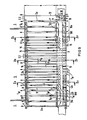
- Winding rods St10 (see FIG. 2) of the stator winding St1 are inserted into slots N (see FIG. 3) on the inner circumference of the essentially hollow cylindrical stator core 2. These winding bars are insulated from high voltage in the usual way.
- the rotor Ro with rotor winding (not shown in detail) is mounted coaxially within the bore St2 of the stator core 2 with an annular air gap 3, ie centrally to the inner circumference of the stator bore St2 (the shaft bearing is omitted for simplification).
- spacer webs 2.1 are inserted between axially lined-up partial laminated cores 2.2 of the stator laminated core 2 to form radial slots 2a, 2b for cooling gas, and these radial slots are the annular air gap spaces 4a, 4b on the inner circumference of the laminated laminated core 2 with chamber spaces 1 or 5 on the outer circumference of the stator core.
- the chamber spaces are either cold gas chambers 1, of which the cold gas is pressed radially inwards through radial cold gas slots 2a into associated first air gap spaces 4a according to flow arrows f K.
- the chamber spaces are hot gas chambers 5, into which heated cooling gas flows in accordance with arrows f w from second air gap spaces 4b via radial warm gas slots 2b directed radially outward.
- the exhaust gas volume to the hot gas chambers 5 is influenced by gas inlets or outlets at the air gap inlet 6 (end faces) and by the cooling gases f R of the rotor Ro.
- the radial cooling slots 2a, 2b are formed by spacers 2.1 in the course of the stratification of the laminated core 2, so that the laminated core is divided into many compact partial laminated cores 2.2.
- Cooling gas blower means and control devices on at least one machine end, preferably on both machine ends, are not shown; However, it is indicated by the flow arrows f R1 of the cooling gas flow entering from both ends below the rotor winding caps R1 and by the flow arrows f S that the cooling gas flow flowing past the winding heads St4 into the stator housing and into the air gap 3 from both machine ends indicates that corresponding fans and guiding devices are to be provided which supply the cooling gas, which is cooled via heat exchangers, not shown, as cold gas to the cold gas chambers 1 and suck the warmed cooling gas out of the warm gas chambers 5 again.
- Sheet metal packs 2.2 can be layered thicker, so that fewer radial slots 2.1 are created.
- metal sheets with the first punched long holes 12 lie from the yoke area into the tooth.
- the axially adjoining sheets are provided with second punched elongated holes 13 in the direction of the tooth tip, which overlap with the preceding elongated holes 12.
- This type of oblong punched oblong holes opens a cooling gas path - axially and radially - through the center of the tooth to the air gap with the channel sections a, b, c, d - see FIGS. 5 to 7; this results in partial packages T1 with the die cut in accordance with FIG. 12 and partial packages T2 with the die cut in accordance with FIG. 13.
- FIGS. 9 and 10 See FIGS. 9 and 10 with the partial sections Xa-Xa, Xb-Xb and Xc-Xc from FIG. 9.
- Overflow channels 14 are stamped into the periphery of the yoke 8 in the entire hot gas or exhaust gas chamber area 5 to the cold gas chamber areas 1. As a result, 5 cold gas from the cold gas chambers can be made available to the entire hot gas chamber area.
- These channels are sealed off from the radial hot gas slots 2b, e.g. B. by suitable spacers 15 in addition to the radially extending spacers 2.10.
- the partial laminated core packages between the hot gas slots 2b are axially divided into partial packages with spacers 2.11 and 17 for each additional radial cold gas slot 16, the cold gas slot 16 being supplied from the overflow channels 14 and having a width a 16 of only approx.
- the teeth in the entire hot gas area are provided with self-contained tooth slots in the form of punched elongated holes 19, so that the cooling gas according to arrows f K from the overflow channels 14 through the radial cold gas slot 16 and the tooth cooling slots according to flow arrows f M , fw to the radial exhaust slots 2b and so that it can flow out to the hot gas chambers 5, see successive channel sections e, f, g, h, i, j. (Fig.9) - Fig.10 shows that the cross section 18 as a throttle can be designed for the purpose of defined quantity control.
- the first tooth packs 20 in the hot gas chambers 5, which connect to the cold gas chambers 1, can be supplied with cold gas directly from the radial cold gas slots 2a from the cold gas chambers 1, see flow arrows f K1 and internal tooth connection channels 19a.
- the sealing sleeves 190 seal the tooth-internal connecting channels 19a to the first hot gas channel 2b at the ends of the area 5.
- the internal tooth cooling according to FIGS. 5 to 8 and the cold gas circuit according to FIGS. 9 and 10 superimposed on the hot gas area can be varied and combined in a corresponding manner.
- Fig. 11 The radial extent of the channel section or flow area c 'is greater than at c of Fig. 5; following c 'fork according to e' on two radial slots, see d ', which are axially one behind the other. 111 to 13, hole punchings M1 and slot punchings M2, the latter in the direction of the heat flow, are also indicated in this exemplary embodiment. Arranged in the extension area of the elongated holes 12.1, 12.2, 13.1, these punchings M1, M2 can be used to adapt the magnetic resistances and to reduce or prevent axial compensation flows.
- FIG. 12 section XII-XII from FIG. 11 with die cuts 12.1, 12.2;
- FIG. 13 section XIII-XI11 from FIG. 11 with punch cut 13.1.
- the teeth in partial laminated core 2.2 can accommodate any cooling gas paths for the cooling circuit of the internal tooth cooling with the opening to the air gap (see FIGS. 5 to 7) and for the cold gas area superimposed on the hot gas area (see FIGS. 9 and 10).
- the embodiment according to FIG. 14 can be addressed as double-acting by using cooling paths, which are shown in section Xa-Xa in FIG ) and shown in section Xc-Xc (right), united within the additional radial cooling slot 16 '.
Description
Die Erfindung bezieht sich auf eine Einrichtung zur indirekten Gaskühlung der Ständerwicklung und/oder zur direkten Gaskühlung des Ständerblechpaketes dynamoelektrischer Maschinen, vorzugsweise für gasgekühlte Turbogeneratoren, gemäß Oberbegriff des Anspruchs 1.The invention relates to a device for indirect gas cooling of the stator winding and / or for direct gas cooling of the stator core of dynamoelectric machines, preferably for gas-cooled turbogenerators, according to the preamble of
Die Kühlung in den Elektromaschinenständen mit einer Einrichtung gemäß Gattungsbegriff wird in der Regel wie folgt ausgeführt.The cooling in the electrical machine stands with a device according to the generic term is usually carried out as follows.
Aus den Kaltgaskammern strömt Kaltgas durch die radialen Kaltgaschlitze des Blechpaketes zum Luftspalt hin, strömt axial zum Abgasbereich und dann durch radiale Warmgasschlitze zum Blechpaketrücken in die Warmgas- bzw. Abgaskammern. Das Abgasvolumen zu den Abgaskammern wird durch Gaszuführungen oder -abführungen am Luftspalteintritt (Stirnseiten) und durch die Kühlgase des Läufers beeinflußt. Die Radialschlitze, ob nun radiale Kaltgas- oder Warmgasschlitze, werden durch Distanzstege in der Schichtung des Blechpaketes gebildet, so daß das Blechpaket in viele kompakte Teilblechpakete unterteilt ist. Diese Bauform gilt insbesondere bei indirekt luftgekühlten Turbogeneratoren. Diese bekannte Bauform hat verschiedene Nachteile, die weiter unten anhand der Abbildungen Fig. 1 bis Fig. 4 noch näher erläutert und hier deshalb lediglich schlagwortartig zusammemgefaßt werden:Cold gas flows out of the cold gas chambers through the radial cold gas slots of the laminated core to the air gap, flows axially to the exhaust gas area and then through radial hot gas slots to back the laminated core into the hot gas or exhaust gas chambers. The exhaust gas volume to the exhaust gas chambers is influenced by gas inlets or outlets at the air gap inlet (end faces) and by the cooling gases of the rotor. The radial slots, whether radial cold gas or hot gas slots, are formed by spacers in the layering of the laminated core, so that the laminated core is divided into many compact partial laminated cores. This design applies particularly to indirectly air-cooled turbogenerators. This known design has various disadvantages, which are explained in more detail below with reference to FIGS. 1 to 4 and are therefore only summarized here in the following manner:
- - zu große Wärmetauscherflächen im Joch bei im Verhältnis dazu zu geringer Wärmequellendichte und zu kleine Wärmetauscherflächen im Zahnbereich bei im Verhältnis dazu zu hoher Wärmequellendichte;- Too large heat exchanger surfaces in the yoke with a relatively low heat source density and too small heat exchanger surfaces in the tooth area with a too high heat source density;
- - Spaltquerschnitte für das Kühlgas in der Jochmitte mehrfach so groß wie in Zahnmitte, damit schwach genutzter Spalt im Joch, der zu größeren Blechpaket- und Gehäusedurchmessern führt;- Gap cross-sections for the cooling gas in the center of the yoke are several times as large as in the center of the tooth, thus a weakly used gap in the yoke, which leads to larger laminated core and housing diameters;
- - Wärmeabfuhr aus den Teilpaketen über einen axialen Wärmefluß, der infolge der Schichtung einen etwa um den Faktor 15 höheren Wärmewiderstand als derjenige in radialer oder in Umfangsrichtung zu überwinden hat;- Heat dissipation from the partial packages via an axial heat flow, which due to the stratification has to overcome a thermal resistance which is about 15 times higher than that in the radial or circumferential direction;
- - über 70 % der geraden Wicklungslänge des Ständers erfolgt eine Kühlung mit den hohen Wärmewiderständen und den geringen Wärmetauscherflächen;- Over 70% of the straight winding length of the stator is cooled with the high thermal resistance and the small heat exchanger surfaces;
- - das zu den Abgaskammern strömende Kühlgas hat nur ein wenig wirksames Temperaturgefälle zu den Wärmetauscherflächen.- The cooling gas flowing to the exhaust gas chambers has only a little effective temperature gradient to the heat exchanger surfaces.
Der Erfindung liegt die Aufgabe zugrunde, eine gattungsgemäße Einrichtung zu schaffen, welche unter Vermeidung der geschilderten Nachteile einen verbesserten Wärmetausch von den Heißstellen des Ständerblechpaketes zum Kühlgas und damit eine bessere Ausnutzung der Kühlgasströme erbringt. Daraus folgend soll die Maschinenleistung bei gegebener Baugröße gesteigert werden können, so daß insbesondere mit indirekt luftgekühlten Turbogeneratoren in Leistungsbereiche vorgedrungen werden kann, die bisher nur wasserstoffgekühlten Maschinen vorbehalten waren.The invention has for its object to provide a generic device which, while avoiding the disadvantages described, provides an improved heat exchange from the hot spots of the stator core to the cooling gas and thus better utilization of the cooling gas flows. From this, the machine output should be able to be increased for a given size, so that in particular with indirectly air-cooled turbogenerators it is possible to penetrate into performance ranges which were previously reserved only for hydrogen-cooled machines.
Erfindungsgemäß wird die gestellte Aufgabe bei einer gattungsgemäßen Einrichtung durch die im Kennzeichen des Anspruchs 1 angegebenen Merkmale gelöst. Vorteilhafte Weiterbildungen sind in den Unteransprüchen 2 bis 13 angegeben.According to the invention, the object is achieved in a generic device by the features specified in the characterizing part of
Die mit der Erfindung erzielbaren Vorteile gehen aus der nachfolgenden Figurenbeschreibung hervor, in welcher anhand der Abb. Fig. 1 bis Fig. 4 zunächst der Stand der Technik und daran anschließend anhand der Figuren 5 bis 14 mehrere Ausführungsbeispiele der Erfindung erläutert werden.The advantages that can be achieved with the invention are apparent from the following description of the figures, in which the prior art is first explained with reference to FIGS. 1 to 4 and then several exemplary embodiments of the invention are explained with reference to FIGS. 5 to 14.
In der Zeichnung zeigt in schematischer, vereinfachter Darstellung unter Fortlassung der für das Verständnis der Erfindung nicht erforderlichen Teile:
- Fig. 1 eine konventionelle Kühleinrichtung für einen Turbogeneratorständer im Axialschnitt;
- Fig. 2 eine Einzelheit des Zahnbereiches aus Fig. 1;
- Fig. 3 eine Draufsicht auf ein Blechsegment des Ständerblechpaketes zur Definition des Joch-und Zahnbereiches;
- Fig. 4 einen Ständer-Axialbereich der Abgaskammer mit angrenzenden Kaltgaskammern im Ausschnitt.
- 1 shows a conventional cooling device for a turbogenerator stand in axial section;
- FIG. 2 shows a detail of the tooth area from FIG. 1;
- 3 shows a plan view of a sheet metal segment of the stator sheet metal stack for defining the yoke and tooth area;
- Fig. 4 shows a stator axial area of the exhaust chamber with adjacent cold gas chambers in the cutout.
In den Fig. 5 bis 14 sind mehrere Ausführungsbeispiele der Erfindung dargestellt, und zwar in
- Fig. 5 in einem Axialschnitt im Ausschnitts-Detail den Teil eines ersten Ausführungsbeispiels nach der Erfindung, der die Zahninnenkühlung des Kaltgaskammernbereiches betrifft;
- Fig. 6 den Schnitt VI-VI aus Fig. 5;
- Fig. 7 den Schnitt VII-VII aus Fig. 5, wobei in Fig. 6 und 7 lediglich Umfangsteilbereiche dargestellt sind,
- Fig. 8 im Ausschnitt eine diffusorartige und gekrümmte Kühlkanalmündung eines Teilpaketes (Variante zum 1. Ausführungsbeispiel);
- Fig. 9 das 1. Ausführungsbeispiel, vervollständigt durch ein im Axialschnitt dargestelltes im Axialbereich einer Warmgaskammer angeordnetes Teilkühlsystem für das betreffende Teilblechpaket, so daß ein überlagertes Warmgas-Kaltgas-Kühlsystem gebildet ist;
- Fig. 10 in drei achsnormalen Teilschnitten Xa-Xa, Xb-Xb und Xc-Xc den Gegenstand nach Fig. 9 auf einem Teilumfang des Ständerblechpaketes;
- Fig. 11 ein zweites Ausführungsbeispiel für die Zahninnenkühlung in entsprechender Darstellung wie Fig. 5;
- Fig. 12 den Schnitt XII-XII aus Fig. 11;
- Fig. 13 den Schnitt XIII-XIII aus Fig. 11;
- Fig. 14 in. der Einzelheit eines Zahnbereiches ein weiteres Ausführungsbeispiel zur Trennung der Kaltgas- von den Warmgasströmen für eine Ausführung nach Fig. 9.
- 5 shows, in an axial section in detail, the part of a first exemplary embodiment according to the invention which relates to the internal cooling of the tooth of the cold gas chamber area;
- 6 shows the section VI-VI from FIG. 5;
- 7 shows the section VII-VII from FIG. 5, only partial peripheral regions being shown in FIGS. 6 and 7,
- 8 shows a diffuser-like and curved cooling channel opening of a partial package (variant of the first exemplary embodiment);
- 9 shows the first exemplary embodiment, completed by a partial cooling system for the partial laminated core in question, arranged in the axial area of a hot gas chamber, so that a superimposed hot gas / cold gas cooling system is formed;
- 10 in three axially normal partial sections Xa-Xa, Xb-Xb and Xc-Xc the object according to FIG. 9 on a partial circumference of the stator core;
- 11 shows a second exemplary embodiment for internal tooth cooling in a representation corresponding to FIG. 5;
- 12 shows the section XII-XII from FIG. 11;
- 13 shows the section XIII-XIII from FIG. 11;
- 14 shows, in the detail of a tooth region, a further exemplary embodiment for separating the cold gas from the hot gas flows for an embodiment according to FIG. 9.
Die folgenden Abschnitte und II der Figurenbeschreibung sind zur besseren Übersicht mit Kapitelüberschriften versehen. 1The following sections and II of the description of the figures are provided with chapter headings for a better overview. 1
Im folgenden wird ein übliches System zur Kühlung von Elektromaschinenständern zunächst anhand von Fig. 1 beschrieben. Die darin verwendeten Bezugszeichen bedeuten:
- 1 Kaltgaskammer
- 2 Blechpaket mit Radialschlitzen
- 3 Luftspalt
- 4 Warmgasbereich (Fig. 4)
- 5 Warmgaskammer
- 6 Gasführung am Luftspalteintritt
- 7 Wärmetauscherflächen der Bleche für Kühlgas
- St Stator bzw. Ständer des Turbogenerators
- Ro Rotor bzw. Läufer des Turbogenerators
- St1 Ständerwicklung
- R1 Wickelkopfkappen des Rotors Ro
- 2a Radialschlitze für Kaltgas
- 2b Radialschlitze für Abgas
- 4a erste Luftspalträume
- 4b zweite Luftspalträume
- St2 Ständerbohrung
- N Nuten
- 1 cold gas chamber
- 2 laminated core with radial slots
- 3 air gap
- 4 hot gas area (FIG. 4)
- 5 hot gas chamber
- 6 Gas routing at the air gap inlet
- 7 heat exchanger surfaces of the sheets for cooling gas
- St stator or stator of the turbogenerator
- Ro rotor or rotor of the turbogenerator
- St1 stator winding
- R1 end caps of the rotor Ro
- 2a radial slots for cold gas
- 2b radial slots for exhaust gas
- 4a first air gap spaces
- 4b second air gap spaces
- St2 stator bore
- N grooves
Die in den Fig. 1 bis 5 dargestellte Einrichtung dient zur indirekten Gaskühling der Ständerwicklung St1 und zugleich zur direkten Gaskühlung des Ständerblechpaketes 22 der in Fig. 1 schematisch dargestellten dynamoelektrischen Maschine, bei der es sich um einen im Ständer St und Läufer luftgekühlten Turbogenerator handelt. Die Erfindung umfaßt indessen auch allgemein gasgekühlte, z. B. H2- ge-kühlte dynamoelektrische Maschinen,ebenso solche, deren Ständerwicklung direkt mit Gas oder Flüssigkeit gekühlt ist. In Nuten N (siehe Fig. 3) am Innenumfang des im wesentlichen hohlzylindrischen Ständerblechpaketes 2 sind Wicklungsstäbe St10 (siehe Fig. 2) der Ständerwicklung St1 eingelegt. Diese Wicklungsstäbe sind in üblicher Weise hochspannungsisoliert. Der Rotor Ro mit Rotorwicklung (nicht näher dargestellt) ist koaxial innerhalb der Bohrung St2 des Ständerblechpaketes 2 mit ringförmigem Luftspalt 3, d. h. zentrisch zum Innenumfang der Ständerbohrung St2, umlaufend gelagert (die Wellenlagerung ist zur Vereinfachung weggelassen).1 to 5 serves for indirect gas cooling of the stator winding St1 and at the same time for direct gas cooling of the stator core 22 of the dynamo-electric machine shown schematically in FIG. 1, which is an air-cooled turbogenerator in the stator and rotor. However, the invention also generally includes gas-cooled, e.g. B. H 2 - ge-cooled dynamoelectric machines, as well as those whose stator winding is directly cooled with gas or liquid. Winding rods St10 (see FIG. 2) of the stator winding St1 are inserted into slots N (see FIG. 3) on the inner circumference of the essentially hollow
Zum besseren Verständnis der folgenden Ausführung sei zunächst auf die in den Figuren 2 bis 4 noch ergänzend verwendeten Bezugszeichen wie folgt hingewiesen:
- Fig. 2:
- 2.1 Radialschlitz-Distanzstege
- 2.2 kompakte Teilblechpakete
- Fig. 2:
- 2.1 Radial slot spacers
- 2.2 compact sheet metal packages
St10 einzelner Stab der aus einer Stabvielzahl bestehenden Ständerwicklung St1
- 10 Richtung des axialen Wärmeflusses
- Fig. 3 und Fig. 4
- St3
Blechsegmente des Ständerblechpaketes 2 - 8 Flächen im Jochbereich der Blechsegmente St3
- 9 Flächen im Zahnbereich
- fK Strömungspfeile für Kaltgas
- fw Strömungspfeile für Warmgas
- fR Strömungspfeile für aus dem Rotor Ro austretendes Kühlgas
- fM Strömungspfeile für aus Kalt- und Rotor-Abgas gemischtes
Mischgas im Luftspalt 3.
- 10 Direction of axial heat flow
- 3 and 4
- St3 sheet metal segments of the
stator core 2 - 8 areas in the yoke area of the sheet metal segments St3
- 9 surfaces in the tooth area
- f K flow arrows for cold gas
- f w Flow arrows for hot gas
- f R flow arrows for cooling gas emerging from the rotor Ro
- f M flow arrows for mixed gas mixed from cold and rotor exhaust gas in the
air gap 3.
Man erkennt aus Fig. 1 bis Fig. 4, daß zwischen axial aneinandergereihten Teilblechpaketen 2.2 des Ständerblechpaketes 2 Distanzftege 2.1 unter Bildung von Radialschlitzen 2a, 2b für Kühlgas eingefügt sind und diese Radialschlitze die ringförmigen Luftspalträume 4a, 4b am Innenumfang des Ständerblechpaketes 2 mit Kammerräumen 1 bzw. 5 am Außenumfang des Ständerblechpaketes verbinden. Bei den Kammerräumen handelt es sich entweder um Kaltgaskammern 1, von denen das Kaltgas gemäß Strömungspfeilen fK radial einwärts durch radiale Kaltgasschlitze 2a in zugehörige erste Luftspalträume 4a gedrückt wird. Andererseits handelt es sich bei den Kammerräumen um Warmgaskammern 5, in welche aufgewärmtes Kühlgas gemäß Pfeilen fw aus zweiten Luftspalträumen 4b über radiale Warmgasschlitze 2b radial auswärts gerichtet einströmt. Das Abgasvolumen zu den Warmgaskammern 5 wird durch Gaszuführungen oder -abführungen am Luftspalteintritt 6 (Stirnseiten) und durch die Kühlgase fR des Läufers Ro beeinflußt. Wie erwähnt, werden die radialen Kühlschlitze 2a, 2b durch Distanzstege 2.1 im Zuge der Schichtung des Blechpaketes 2 gebildet, so daß das Blechpaket in viele kompakte Teilblechpakete 2.2 unterteilt ist. Kühlgas-Gebläsemittel und -Leiteinrichtungen an mindestens einem Maschinenende, vorzugsweise an beiden Maschinenenden, sind nicht dargestellt; durch die Strömungspfeile fR1 der unterhalb der Rotorwicklungskappen R1 von beiden Enden her eintretenden Kühlgasströmung und durch die Strömungspfeile fS, der an den Wickelköpfen St4 vorbei in das Ständergehäuse und in den Luftspalt 3 von beiden Maschinenenden her einströmenden Kühlgasströmung ist jedoch angedeutet, daß entsprechende Lüfter und Leiteinrichtungen vorzusehen sind, welche das über nicht dargestellte Wärmetauscher gekühlte Kühlgas als Kaltgas den Kaltgaskammern 1 zuleiten und das aufgewärmte Kühlgas aus den Warmgaskammern 5 wieder absaugen.It can be seen from FIG. 1 to FIG. 4 that spacer webs 2.1 are inserted between axially lined-up partial laminated cores 2.2 of the stator laminated
Die Nachteile dieses bekannten Kühlsystems:
- 1. Die Wärmetauscherflächen sind im Joch 8 - vergleiche Fig. 3 - bei geringer Wärmequellendichte groß.
- 2. Die Wärmetauscherflächen sind
im Zahnbereich 9 bei hoher Wärmequellendichte klein. - 3. Die Spaltquerschnitte für das Kühlgas sind in der Jochmitte fast dreimal so groß wie in der Zahnmitte. Der schwach genutzte Spalt im Joch führt aber zu größeren Blechpaket- und Gehäusedurchmessern.
- 4. Die Wärmeabfuhr aus den Teilpaketen geschieht über einen axialen Wärmefluß 10, der infolge der Schichtung einen Wärmewiderstand zu überwinden hat, der um
den Faktor 15 höher ist als in radialer Richtung oder Umfangsrichtung. - 5. Da die Wicklungen im Blechpaketbereich zu über 70 % in den Teilblechpaketen liegen, wird für über 70 % der geraden Wicklungslänge nur eine Kühlung mit den hohen Wärmewiderständen und den geringen Wärmetauscherflächen entsprechend 4.
und 2. wirksam. - 6. Das Kühlgas, das zu
den Abgasbereichen 5 strömt, hat nur ein wenig wirksames Temperaturgefälle zu den Wärmetauscherflächen 7 (siehe Fig. 4). Gründe dafür:- - Zu hohe Kühlgastemperatur durch die Aufnahme folgender Verluste: Lüfterverluste, Wickelkopfverluste, Blechpaket- und Wicklungsverluste der Kaltgaskammernbereiche und die Gasreibungsverluste im Luftspalt. Hinzu kommen die heißen Kühlgase des Läufers, die im Luftspalt durch Gasreibung zusätzlich aufgewärmt werden.
- - Verlorenes Wärmegefälle vom Wicklungskupfer zu den Wärmetauscherflächen infolge der Wärmewiderstände entsprechen vorstehender Ziffer 4.
- - Die Kühlwirkung kann nur in engen Grenzen dadurch verbessert werden, daß die vorhergehende Aufwärmung durch noch größere Gasmengen reduziert wird: Gasmengenprobleme, höhere Lüfterverluste, teurere Rückkühlung. 11
- 1. The heat exchanger surfaces are large in the yoke 8 - see FIG. 3 - with a low heat source density.
- 2. The heat exchanger surfaces are small in the
tooth area 9 with a high heat source density. - 3. The gap cross sections for the cooling gas are almost three times as large in the center of the yoke as in the center of the tooth. The weakly used gap in the yoke leads to larger laminated core and Housing diameters.
- 4. The heat dissipation from the partial packages takes place via an
axial heat flow 10, which due to the stratification has to overcome a thermal resistance which is 15 times higher than in the radial direction or circumferential direction. - 5. Since the windings in the laminated core area are more than 70% in the partial laminated core, only cooling with the high thermal resistances and the small heat exchanger surfaces corresponding to 4th and 2nd is effective for over 70% of the straight winding length.
- 6. The cooling gas which flows to the
exhaust gas areas 5 has only a slightly effective temperature gradient to the heat exchanger surfaces 7 (see FIG. 4). Reasons:- - The cooling gas temperature is too high due to the absorption of the following losses: fan losses, winding head losses, laminated core and winding losses in the cold gas chamber areas and the gas friction losses in the air gap. In addition, there are the hot cooling gases of the rotor, which are additionally warmed up in the air gap by gas friction.
- - Lost heat gradient from the winding copper to the heat exchanger surfaces as a result of the heat resistance corresponds to section 4 above.
- - The cooling effect can only be improved within narrow limits by reducing the previous warming up by even larger quantities of gas: problems with the quantity of gas, higher fan losses, more expensive recooling. 11
Im folgenden wird ein wirksames Kühlsystem für indirekt gekühlte Ständerwicklungen mit einer Zahninnenkühlung und einem überlagerten Kaltgaskreis in den Warmgaskammern beschrieben. Zunächst derAn effective cooling system for indirectly cooled stator windings with internal tooth cooling and a superimposed cold gas circuit in the hot gas chambers is described below. First the
Teilblechpakete 2.2 können dicker geschichtet werden, so daß weniger Radialschlitze 2.1 entstehen. An den Radialschlitzen liegen Bleche mit ersten gestanzten L.anglöchern 12 vom Jochbereich bis in den Zahn hinein an. Die axial anschließenden Bleche werden mit zweiten gestanzten Langlöchern 13 in Richtung Zahnkopf versehen, die mit den vorhergehenden Langlöchern 12 überlappen. Durch diese Art der versetzt gestanzten Langlöcher wird ein Kühlgasweg - axial und radial - durch die Zahnmitte bis hin zum Luftspalt geöffnet mit den Kanalabschnitten a, b, c, d - siehe Fig. 5 bis 7 -; es ergeben sich damit Teilpakete T1 mit dem Stanzschnitt gemäß 12 und Teilpakete T2 mit dem Stanzschnitt gemäß 13.Sheet metal packs 2.2 can be layered thicker, so that fewer radial slots 2.1 are created. At the radial slots, metal sheets with the first punched
- 1. Die Wärmetauscherflächen im Joch werden der geringeren Wärmequellendichte angepaßt.1. The heat exchanger surfaces in the yoke are adapted to the lower heat source density.
- 2. Die Wärmetauscherflächen im Zahnbereich sind bei hoher Wärmequellendichte recht groß.2. The heat exchanger surfaces in the tooth area are quite large with a high heat source density.
- 3. Die Spaltquerschnitte für das Kühlgas sind im Verhältnis Joch zu Zahnbereich besser angepaßt.3. The gap cross sections for the cooling gas are better adapted in relation to the yoke to the tooth area.
- 4. Die Wärmeabfuhr aus der Wicklung innerhalb der Teilblechpakete kann auf kurzem Weg in Blechtafelrichtung zu den Langlöchern als Kühlgaswege im Zahn erfolgen. - Geringer Wärmewiderstand, ca. 90 % weniger -.4. The heat dissipation from the winding within the partial laminated cores can take place over a short distance in the direction of the metal sheet to the elongated holes as cooling gas paths in the tooth. - Low thermal resistance, about 90% less -.
- 5. Für die Wärmeabfuhr im Zahnbereich stehen große Wärmetauscherflächen zur Verfügung.5. Large heat exchanger surfaces are available for heat dissipation in the tooth area.
- 6. Der Austritt aus den Zahnschlitzen zum Luftspalt kann strömungstechnisch günstig gestaltet werden, siehe diffusorartige Schlitzgestaltung gemäß Fig. 8, wonach die Mündung 13a des Kühlgasauslaßschlitzes (13) diffusorartig erweitert ist.6. The outlet from the tooth slots to the air gap can be designed to be fluidly favorable, see diffuser-like slot design according to FIG. 8, after which the mouth 13a of the cooling gas outlet slot (13) is expanded like a diffuser.
Siehe Fig. 9 und 10 mit den Teilschnitten Xa-Xa, Xb-Xb und Xc-Xc aus Fig. 9.See FIGS. 9 and 10 with the partial sections Xa-Xa, Xb-Xb and Xc-Xc from FIG. 9.
In die Peripherie des Joches 8 im gesamten Warmgas- bzw. Abgaskammerbereich 5 werden zu den Kaltgaskammernbereichen 1 hin Überströmkanäle 14 eingestanzt. Hierdurch kann dem gesamten Warmgaskammernbereich 5 Kaltgas aus den Kaltgaskammern zur Verfügung gestellt werden. Diese Kanäle werden zu den radialen Warmgasschlitzen 2b hin abgedichtet, z. B. durch geeignete Distanzstege 15 zusätzlich zu den radial verlaufenden Distanzstegen 2.10. Die Teilblechpakete zwischen den Warmgasschlitzen 2b werden mit Distanzstegen 2.11 und 17 für je einen zusätzlichen radialen Kaltgasschlitz 16 in Teilpakete axial unterteilt, wobei der Kaltgasschlitz 16 von den Überströmkanälen 14 her versorgt wird und in seiner Weite a16 nur ca. 1/5 - 1/2, insb. 1/3 der Weite a2b der Warmgasschlitze 2b beträgt. Diese Kaltgasschlitze 16 müssen zum Rücken hin abgedichtet sein, z. B. durch die tangential verlaufenden Distanzstege 17, die zusätzlich zu den radial verlaufenden Distanzstegen 2.11 vorgesehen sind. Am Zahnkopf kann ein durch distanzierende Stege 170 freigelassener geringer Querschnitt 18 geöffnet bleiben, damit die gesamte Zahnfläche zur Kühlung genutzt werden kann, und Fremdpartikel wieder zum Luftspalt ausgeworfen werden können. Die Zähne im gesamten Warmgasbereich werden mit in sich geschlossenen Zahnschlitzen in Form gestanzter Langlöcher 19 versehen, so daß das Kühlgas gemäß Pfeilen fK von den Überströmkanälen 14 her durch den radialen Kaltgasschlitz 16 und die Zahnkühlschlitze gemäß Strömungspfeilen fM, fw zu den radialen Abgasschlitzen 2b und damit zu den Warmgaskammern 5 hin abströmen kann, siehe in Strömungsrichtung aufeinanderfolgende Kanalabschnitte e, f, g, h, i, j. (Fig.9) - Fig.10 zeigt noch, daß der Querschnitt 18 als Drosselstelle ausgebildet sein kann zwecks definierter Mengensteuerung.
Zur Entlastung der Überströmkanäle können die ersten Zahnpakete 20 in den Warmgaskammern 5, die an die Kaltgaskammern 1 anschließen, direkt von den radialen Kaltgasschlitzen 2a aus den Kaltgaskammern 1 mit Kaltgas versorgt weräen, siehe Strömungspfeile fK1 und zahninterne Verbindungskanäle 19a. Die Abdichthülsen 190 dichten die zahninternen Verbindungskanäle 19a zum ersten Warmgaskanal 2b an den Enden des Bereiches 5 ab.To relieve the overflow channels, the first tooth packs 20 in the
- 1. Der überlagerte Kühlkreislauf zielt genau auf den Engpaß der Kühlung, nämlich die Abführung der Kurzschlußverluste im Warmgaskammernbereich 4 der Ständerwicklung St1.1. The superimposed cooling circuit aims precisely at the bottleneck of the cooling, namely the removal of the short-circuit losses in the hot gas chamber area 4 of the stator winding St1.
-
2. Die Gasmenge kann für die Verluste ausgelegt werden, die in diesem Bereich zusätzlich abgeführt werden sollen. Dabei wird der überlagerte Kühlkreislauf, außer von den Kurzschlußverlusten, nur noch von den Blechpaketverlusten beeinflußt.
- (Beträgt die Länge einer Warmgaskammer nur ca. 15 % einer Stablänge, und sollen zusätzlich zum konventionellen System 50 % Verluste abgeführt werden, so kann die Berechnung des überlagerten Kaltgaskreises auf 7,5 % der Kurzschlußverluste unter zusätzlicher Berücksichtigung der Blechpaketverluste beschränkt bleiben).
- (If the length of a hot gas chamber is only approx. 15% of a rod length and if, in addition to the conventional system, 50% losses are to be dissipated, the calculation of the superimposed cold gas circuit can be limited to 7.5% of the short circuit losses, with additional consideration of the laminated core losses).
- 3. Das Kaltgas in Verbindung mit den zur Gasmenge großen Wärmetauscherflächen und den geringen Wärmewiderständen von den Wärmequellen zu den Wärmetauscherflächen hin ergibt eine sehr hohe Gasaufwärmung und damit eine extrem günstige Wärmeabfuhr.3. The cold gas in connection with the large amount of heat exchanger surfaces and the low thermal resistances from the heat sources to the heat exchanger surfaces results in a very high gas heating and thus extremely favorable heat dissipation.
- 4. Der überlagerte Kuhlkreislauf kann auf die Warmgaskammer(n) 5 beschränkt bleiben, die im mittleren Maschinenbereich die höchste(n) Aufwärmung(en) hat (haben). Abgasbereiche an den Maschinenenden werden über den Luftspalt mit Kaltgas versorgt.4. The superimposed cooling circuit can be limited to the hot gas chamber (s) 5, which has the highest warm-up (s) in the middle machine area. Exhaust areas at the machine ends are supplied with cold gas through the air gap.
- 5. In Verbindung mit einer Saugbelüftung können die Abgasbereiche minimiert und das Blechpaket dichter geschichtet werden (geringe Gasmenge, hohe Aufwärmung durch die Zahninnenkülung, direkte Abführung durch den Luftspalt).5. In connection with suction ventilation, the exhaust gas areas can be minimized and the laminated core can be layered more densely (small amount of gas, high warming up through the internal cooling of the teeth, direct discharge through the air gap).
Die Zahninnenkühlung entsprechend Fig. 5 bis 8 und der dem Warmgasbereich überlagerte Kaltgaskreis entsprechend Fig. 9 und Fig. 10 können sinngemäß variiert und kombiniert werden.The internal tooth cooling according to FIGS. 5 to 8 and the cold gas circuit according to FIGS. 9 and 10 superimposed on the hot gas area can be varied and combined in a corresponding manner.
Fig. 11 Die Radialerstreckung des Kanalabschnitts bzw. Strömungsbereiches c' ist größer als bei c von Fig. 5; im Anschluß an c' Aufgabelung gemäß e' auf zwei Radialschlitze, siehe d', die axial hintereinanderliegen. In diesem Ausführungsbeispiel sind in Fig. 111 bis 13 ferner Lochstanzungen M1 bzw. Langlochstanzungen M2, letztere in Richtung des Wärmeflusses angedeutet. Im Verlängerungsbereich der Langlöcher 12.1, 12.2, 13.1 angeordnet, können durch diese Stanzungen M1, M2 die magnetischen Widerstände angepaßt und axiale Ausgleichsflüsse verringert oder verhindert werden.Fig. 11 The radial extent of the channel section or flow area c 'is greater than at c of Fig. 5; following c 'fork according to e' on two radial slots, see d ', which are axially one behind the other. 111 to 13, hole punchings M1 and slot punchings M2, the latter in the direction of the heat flow, are also indicated in this exemplary embodiment. Arranged in the extension area of the elongated holes 12.1, 12.2, 13.1, these punchings M1, M2 can be used to adapt the magnetic resistances and to reduce or prevent axial compensation flows.
Fig. 12 Schnitt XII-XII aus Fig. 11 mit Stanzschnitten 12.1, 12.2;FIG. 12 section XII-XII from FIG. 11 with die cuts 12.1, 12.2;
Fig. 13 Schnitt XIII-XI11 aus Fig. 11 mit Stanzschnitt 13.1.FIG. 13 section XIII-XI11 from FIG. 11 with punch cut 13.1.
Die Zähne in Teilblechpaket 2.2 können beliebige Kühlgaswege für den Kühlkreis der Zahninnenkühlung mit der Öffnung zum Luftspalt (vgl. Fig. 5 bis 7) und für den dem Warmgasbereich überlagerten Kaltgasbereich (vgl. Fig. 9 und 10) aufnehmen. Dazu ist mit Vorteil eine Trennung beider Kühlsysteme durch einen V-förmig gebogenen Distanzsteg 21 in dem zusätzlichen radialen Kaltgasschlitz 16 erforderlich, siehe Fig. 14, wo mit 19' über den Zahn- und Nutengrundbereich verteilte gestanzte Langlöcher und mit 19" eine Variation in Form von Lochstanzungen bezeichnet sind, ferner mit 13' der vom Luftspaltraum 4b her mit Mischgas fM beaufschlagte Zahnschlitz. Die Ausführung nach Fig. 14 kann als doppelt wirkend angesprochen werden, indem sie Kühlpfade, die in Fig. 10 im Schnitt Xa-Xa (links) und im Schnitt Xc-Xc (rechts) dargestellt sind, innerhalb des zusätzlichen radialen Kühlschlitzes 16' vereinigt.The teeth in partial laminated core 2.2 can accommodate any cooling gas paths for the cooling circuit of the internal tooth cooling with the opening to the air gap (see FIGS. 5 to 7) and for the cold gas area superimposed on the hot gas area (see FIGS. 9 and 10). For this purpose, it is advantageous to separate the two cooling systems by means of a V-shaped
3. Glättung der Innenbohrung Das System ermöglicht den Verzicht auf die Zahnkopfkühlung im Luftspalt. Die Streukanäle zwischen den Ständerzahnköpfen innerhalb der radialen Kühlgasschlitze 2a, 2b können ausgefüllt und hier entstehende Verwirbelungsverluste verringert werden.3. Smoothing the inner bore The system makes it possible to dispense with cooling of the tooth tips in the air gap. The scattering channels between the stator tooth heads within the radial
Claims (13)
characterised in that
Priority Applications (1)
| Application Number | Priority Date | Filing Date | Title |
|---|---|---|---|
| AT84116326T ATE30652T1 (en) | 1984-03-21 | 1984-12-27 | DEVICE FOR INDIRECT GAS COOLING OF THE STATION DEVELOPMENT AND/OR FOR DIRECT GAS COOLING OF THE STATION PLATE PACKAGE OF DYNAMOELECTRIC MACHINES, PREFERABLY FOR GAS-COOLED TURBO GENERATORS. |
Applications Claiming Priority (4)
| Application Number | Priority Date | Filing Date | Title |
|---|---|---|---|
| DE3410392 | 1984-03-21 | ||
| DE3410392 | 1984-03-21 | ||
| DE19843444189 DE3444189A1 (en) | 1984-03-21 | 1984-12-04 | DEVICE FOR INDIRECT GAS COOLING OF THE STATE DEVELOPMENT AND / OR FOR DIRECT GAS COOLING OF THE STATE SHEET PACKAGE OF DYNAMOELECTRICAL MACHINES, PREFERRED FOR GAS COOLED TURBOGENERATORS |
| DE3444189 | 1984-12-04 |
Publications (2)
| Publication Number | Publication Date |
|---|---|
| EP0155405A1 EP0155405A1 (en) | 1985-09-25 |
| EP0155405B1 true EP0155405B1 (en) | 1987-11-04 |
Family
ID=25819571
Family Applications (1)
| Application Number | Title | Priority Date | Filing Date |
|---|---|---|---|
| EP84116326A Expired EP0155405B1 (en) | 1984-03-21 | 1984-12-27 | Device for indirect gas cooling of stator windings and/or for the direct gas cooling of stator laminated magnetic cores of a dynamo-electric machine, particularly for gas-cooled turbogenerators |
Country Status (2)
| Country | Link |
|---|---|
| EP (1) | EP0155405B1 (en) |
| DE (2) | DE3444189A1 (en) |
Cited By (20)
| Publication number | Priority date | Publication date | Assignee | Title |
|---|---|---|---|---|
| US6261437B1 (en) | 1996-11-04 | 2001-07-17 | Asea Brown Boveri Ab | Anode, process for anodizing, anodized wire and electric device comprising such anodized wire |
| US6279850B1 (en) | 1996-11-04 | 2001-08-28 | Abb Ab | Cable forerunner |
| US6357688B1 (en) | 1997-02-03 | 2002-03-19 | Abb Ab | Coiling device |
| US6369470B1 (en) | 1996-11-04 | 2002-04-09 | Abb Ab | Axial cooling of a rotor |
| US6376775B1 (en) | 1996-05-29 | 2002-04-23 | Abb Ab | Conductor for high-voltage windings and a rotating electric machine comprising a winding including the conductor |
| US6396187B1 (en) | 1996-11-04 | 2002-05-28 | Asea Brown Boveri Ab | Laminated magnetic core for electric machines |
| US6417456B1 (en) | 1996-05-29 | 2002-07-09 | Abb Ab | Insulated conductor for high-voltage windings and a method of manufacturing the same |
| US6429563B1 (en) | 1997-02-03 | 2002-08-06 | Abb Ab | Mounting device for rotating electric machines |
| US6439497B1 (en) | 1997-02-03 | 2002-08-27 | Abb Ab | Method and device for mounting a winding |
| US6465979B1 (en) | 1997-02-03 | 2002-10-15 | Abb Ab | Series compensation of electric alternating current machines |
| US6525265B1 (en) | 1997-11-28 | 2003-02-25 | Asea Brown Boveri Ab | High voltage power cable termination |
| US6525504B1 (en) | 1997-11-28 | 2003-02-25 | Abb Ab | Method and device for controlling the magnetic flux in a rotating high voltage electric alternating current machine |
| US6577487B2 (en) | 1996-05-29 | 2003-06-10 | Asea Brown Boveri Ab | Reduction of harmonics in AC machines |
| US6646363B2 (en) | 1997-02-03 | 2003-11-11 | Abb Ab | Rotating electric machine with coil supports |
| US6801421B1 (en) | 1998-09-29 | 2004-10-05 | Abb Ab | Switchable flux control for high power static electromagnetic devices |
| US6822363B2 (en) | 1996-05-29 | 2004-11-23 | Abb Ab | Electromagnetic device |
| US6825585B1 (en) | 1997-02-03 | 2004-11-30 | Abb Ab | End plate |
| US6828701B1 (en) | 1997-02-03 | 2004-12-07 | Asea Brown Boveri Ab | Synchronous machine with power and voltage control |
| US6831388B1 (en) | 1996-05-29 | 2004-12-14 | Abb Ab | Synchronous compensator plant |
| DE102016222331A1 (en) * | 2016-11-14 | 2018-05-17 | Bayerische Motoren Werke Aktiengesellschaft | Stator for an electrical machine, in particular a motor vehicle, as well as an electric machine, in particular for a motor vehicle |
Families Citing this family (21)
| Publication number | Priority date | Publication date | Assignee | Title |
|---|---|---|---|---|
| DE3481769D1 (en) * | 1984-01-23 | 1990-05-03 | Takeda Chemical Industries Ltd | CEPHEM DERIVATIVES AND THEIR PRODUCTION. |
| DE3703594A1 (en) * | 1987-02-06 | 1988-09-08 | Bbc Brown Boveri & Cie | GAS-COOLED ELECTRICAL MACHINE |
| GB2289992B (en) * | 1994-05-24 | 1998-05-20 | Gec Alsthom Ltd | Improvements in or relating to cooling arrangements in rotating electrical machines |
| RU2193813C2 (en) * | 1996-05-29 | 2002-11-27 | Абб Аб | Axially cooled rotary electrical machine |
| DE19942881A1 (en) * | 1999-09-08 | 2001-03-15 | Asea Brown Boveri | Air-cooled electrical generator has 3-chamber cooling with warm air chamber having different axial lengths for optimising cooling gas distribution |
| CH698519B1 (en) * | 2006-01-24 | 2009-08-31 | Alstom Technology Ltd | Press plate laminates of the laminated stator of an electrical machine. |
| DE102006049188B3 (en) | 2006-10-14 | 2008-03-27 | Antriebstechnik Katt Hessen Gmbh | Cooling system for rotary electrical machine i.e. three-phase machine, has radial housing discharge openings arranged with open channels during construction of housing at points of stator partial laminated cores |
| CN101123381B (en) * | 2007-09-14 | 2010-06-16 | 哈尔滨电机厂有限责任公司 | Full air cooling system for huge water wheel generator |
| US20110266896A1 (en) * | 2010-04-30 | 2011-11-03 | Alstom Hydro France | Rotating electric machine |
| US9225208B2 (en) * | 2011-09-30 | 2015-12-29 | Hamilton Sundstrand Corporation | Internal cooling of magnetic core for electric machine |
| WO2013170883A1 (en) * | 2012-05-15 | 2013-11-21 | Abb Oy | Stator for electric machine |
| GB2526253A (en) * | 2014-04-11 | 2015-11-25 | Nenad Paunovic | Electro motor or generator teeth based cooling system |
| CN104065185B (en) * | 2014-06-13 | 2017-02-15 | 北京交通大学 | Multi-way soaking type motor |
| US10411563B2 (en) | 2015-01-30 | 2019-09-10 | Prippell Technologies, Llc | Electric machine stator with liquid cooled teeth |
| EP3157138B1 (en) * | 2015-10-12 | 2018-07-25 | Siemens Aktiengesellschaft | Method for cooling a stack of metal sheets, stack of metal sheets, rotor, stator and electric machine |
| DE102019114264A1 (en) * | 2019-05-28 | 2020-12-03 | Nidec Gpm Gmbh | Stator with liquid-cooled stator core |
| CN110460180B (en) * | 2019-08-30 | 2020-11-03 | 东方电气集团东方电机有限公司 | Method for improving axial temperature distribution uniformity of stator |
| US11411448B2 (en) * | 2019-09-03 | 2022-08-09 | Hamilton Sundstrand Corporation | Motor stator core design with integral cooling duct within teeth |
| CN113726042B (en) * | 2020-05-25 | 2023-09-08 | 乌鲁木齐金风天翼风电有限公司 | Cooling device, generator and wind generating set |
| CN112928840B (en) * | 2021-01-28 | 2022-05-31 | 浙江大学 | Generator stator and generator |
| DE102022109800A1 (en) | 2022-04-22 | 2023-10-26 | Dr. Ing. H.C. F. Porsche Aktiengesellschaft | Stator of an electrical machine and electrical machine |
Family Cites Families (9)
| Publication number | Priority date | Publication date | Assignee | Title |
|---|---|---|---|---|
| DE467201C (en) * | 1928-10-22 | Siemens Schuckertwerke Akt Ges | Electrical machine with radial air channels formed by cutouts from the sheet metal lamellas, regularly distributed around the circumference of the sheet metal body | |
| GB191422383A (en) * | 1914-11-11 | 1915-11-11 | Jan Arthur Kuyser | Improvements relating to Dynamo Electric Machines. |
| FR497839A (en) * | 1919-04-04 | 1919-12-18 | Paul Ehrmann | Improvements to cooling devices for electrical machines |
| DE412513C (en) * | 1921-10-21 | 1925-04-23 | Allg Elek Citaets Ges Fa | Device for cooling electrical machines with subdivided, radial air slots |
| DE590588C (en) * | 1930-09-17 | 1934-01-06 | Aeg | Stand construction for radial ventilation of the stand teeth of electrical machines with stand iron layered from toothed sheets |
| FR717252A (en) * | 1933-12-28 | 1932-01-06 | Improvements to electrical machines with laminated mass | |
| FR782561A (en) * | 1934-01-26 | 1935-06-07 | Ceskomoravska Kolben Danek Sa | Spacer bar device in the radial ventilation ducts between the sheet packs of the turbo-generators |
| US2615938A (en) * | 1951-06-21 | 1952-10-28 | Asea Ab | Ventilation system for electric machines |
| DE2345810C2 (en) * | 1973-09-11 | 1982-03-11 | Kraftwerk Union AG, 4330 Mülheim | Device for cooling the stator teeth of electrical machines |
-
1984
- 1984-12-04 DE DE19843444189 patent/DE3444189A1/en not_active Withdrawn
- 1984-12-27 DE DE8484116326T patent/DE3467273D1/en not_active Expired
- 1984-12-27 EP EP84116326A patent/EP0155405B1/en not_active Expired
Cited By (20)
| Publication number | Priority date | Publication date | Assignee | Title |
|---|---|---|---|---|
| US6417456B1 (en) | 1996-05-29 | 2002-07-09 | Abb Ab | Insulated conductor for high-voltage windings and a method of manufacturing the same |
| US6831388B1 (en) | 1996-05-29 | 2004-12-14 | Abb Ab | Synchronous compensator plant |
| US6822363B2 (en) | 1996-05-29 | 2004-11-23 | Abb Ab | Electromagnetic device |
| US6577487B2 (en) | 1996-05-29 | 2003-06-10 | Asea Brown Boveri Ab | Reduction of harmonics in AC machines |
| US6376775B1 (en) | 1996-05-29 | 2002-04-23 | Abb Ab | Conductor for high-voltage windings and a rotating electric machine comprising a winding including the conductor |
| US6396187B1 (en) | 1996-11-04 | 2002-05-28 | Asea Brown Boveri Ab | Laminated magnetic core for electric machines |
| US6261437B1 (en) | 1996-11-04 | 2001-07-17 | Asea Brown Boveri Ab | Anode, process for anodizing, anodized wire and electric device comprising such anodized wire |
| US6279850B1 (en) | 1996-11-04 | 2001-08-28 | Abb Ab | Cable forerunner |
| US6369470B1 (en) | 1996-11-04 | 2002-04-09 | Abb Ab | Axial cooling of a rotor |
| US6465979B1 (en) | 1997-02-03 | 2002-10-15 | Abb Ab | Series compensation of electric alternating current machines |
| US6439497B1 (en) | 1997-02-03 | 2002-08-27 | Abb Ab | Method and device for mounting a winding |
| US6646363B2 (en) | 1997-02-03 | 2003-11-11 | Abb Ab | Rotating electric machine with coil supports |
| US6357688B1 (en) | 1997-02-03 | 2002-03-19 | Abb Ab | Coiling device |
| US6825585B1 (en) | 1997-02-03 | 2004-11-30 | Abb Ab | End plate |
| US6828701B1 (en) | 1997-02-03 | 2004-12-07 | Asea Brown Boveri Ab | Synchronous machine with power and voltage control |
| US6429563B1 (en) | 1997-02-03 | 2002-08-06 | Abb Ab | Mounting device for rotating electric machines |
| US6525265B1 (en) | 1997-11-28 | 2003-02-25 | Asea Brown Boveri Ab | High voltage power cable termination |
| US6525504B1 (en) | 1997-11-28 | 2003-02-25 | Abb Ab | Method and device for controlling the magnetic flux in a rotating high voltage electric alternating current machine |
| US6801421B1 (en) | 1998-09-29 | 2004-10-05 | Abb Ab | Switchable flux control for high power static electromagnetic devices |
| DE102016222331A1 (en) * | 2016-11-14 | 2018-05-17 | Bayerische Motoren Werke Aktiengesellschaft | Stator for an electrical machine, in particular a motor vehicle, as well as an electric machine, in particular for a motor vehicle |
Also Published As
| Publication number | Publication date |
|---|---|
| EP0155405A1 (en) | 1985-09-25 |
| DE3467273D1 (en) | 1987-12-10 |
| DE3444189A1 (en) | 1985-09-26 |
Similar Documents
| Publication | Publication Date | Title |
|---|---|---|
| EP0155405B1 (en) | Device for indirect gas cooling of stator windings and/or for the direct gas cooling of stator laminated magnetic cores of a dynamo-electric machine, particularly for gas-cooled turbogenerators | |
| EP2368308B1 (en) | Electrical motor havingaxial and radially offsetted cooling stream and related method | |
| DE102008064495B3 (en) | Electric machine with several cooling streams and cooling process | |
| DE102011054250B4 (en) | Ventilated rotor and stator for dynamoelectric machine | |
| EP0279064B1 (en) | Gas-cooled electric machine | |
| DE3047141A1 (en) | LIQUID-COOLED DYNAMO MACHINE | |
| EP0894358B1 (en) | Rotor winding for an electric machine | |
| DE10018642C2 (en) | Rotary electric machine | |
| EP2918005B1 (en) | Reliable cage rotor | |
| DE3334501A1 (en) | Method for producing laminated iron cores for electrical machines and apparatuses, and an arrangement of a laminated iron core produced according to said method | |
| CH323433A (en) | Method and device for cooling electrical conductors in a fully encapsulated dynamo-electric machine | |
| DE102016225342A1 (en) | Housing of an electrical machine, stator assembly of an electrical machine and electrical machine | |
| DE19919040A1 (en) | Electric machine, in particular three-phase machine | |
| EP2076956B1 (en) | Cooling system for highly utilized rotating electrical machines | |
| EP0522210B1 (en) | Cooling system of a rotating electrical machine and electrical machine for carrying out such a system | |
| DE102012204197A1 (en) | Electric machine with phase separator | |
| EP1204193B1 (en) | Cooling system for a low inertia rotating electric machine | |
| EP0160887A2 (en) | Device for enforced rotorwinding gas cooling of dynamoelectric machines, especially of turbogenerators | |
| DE10020705A1 (en) | Rotary electric machine with cooling arrangement, has ventilation passage in most external diameter turn of rotor winding wire, which contacts chestnut page block axially and continuously | |
| DE10225221B4 (en) | Ventilation of a ring motor for a tube mill | |
| EP1062719A1 (en) | Ventilation system for the excitation winding of large salient-pole machines | |
| EP1032113A1 (en) | Cooling for an electric machine, in particular for a rotating field machine | |
| DE102020122523A1 (en) | Cooled rotor of an electrical machine | |
| DE102021111700A1 (en) | end winding cooling | |
| DE102022207210A1 (en) | Cooled rotor arrangement with enlarged rotor shaft holder |
Legal Events
| Date | Code | Title | Description |
|---|---|---|---|
| PUAI | Public reference made under article 153(3) epc to a published international application that has entered the european phase |
Free format text: ORIGINAL CODE: 0009012 |
|
| AK | Designated contracting states |
Designated state(s): AT CH DE LI |
|
| 17P | Request for examination filed |
Effective date: 19851106 |
|
| 17Q | First examination report despatched |
Effective date: 19861023 |
|
| GRAA | (expected) grant |
Free format text: ORIGINAL CODE: 0009210 |
|
| RAP1 | Party data changed (applicant data changed or rights of an application transferred) |
Owner name: SIEMENS AKTIENGESELLSCHAFT BERLIN UND MUENCHEN |
|
| AK | Designated contracting states |
Kind code of ref document: B1 Designated state(s): AT CH DE LI |
|
| REF | Corresponds to: |
Ref document number: 30652 Country of ref document: AT Date of ref document: 19871115 Kind code of ref document: T |
|
| REF | Corresponds to: |
Ref document number: 3467273 Country of ref document: DE Date of ref document: 19871210 |
|
| PLBI | Opposition filed |
Free format text: ORIGINAL CODE: 0009260 |
|
| PLAB | Opposition data, opponent's data or that of the opponent's representative modified |
Free format text: ORIGINAL CODE: 0009299OPPO |
|
| 26 | Opposition filed |
Opponent name: ASEA BROWN BOVERI AG Effective date: 19880723 |
|
| R26 | Opposition filed (corrected) |
Opponent name: ASEA BROWN BOVERI AG Effective date: 19880822 |
|
| PG25 | Lapsed in a contracting state [announced via postgrant information from national office to epo] |
Ref country code: AT Effective date: 19891227 |
|
| PLBN | Opposition rejected |
Free format text: ORIGINAL CODE: 0009273 |
|
| STAA | Information on the status of an ep patent application or granted ep patent |
Free format text: STATUS: OPPOSITION REJECTED |
|
| 27O | Opposition rejected |
Effective date: 19900308 |
|
| PGFP | Annual fee paid to national office [announced via postgrant information from national office to epo] |
Ref country code: DE Payment date: 19910225 Year of fee payment: 7 |
|
| PGFP | Annual fee paid to national office [announced via postgrant information from national office to epo] |
Ref country code: CH Payment date: 19910322 Year of fee payment: 7 |
|
| PG25 | Lapsed in a contracting state [announced via postgrant information from national office to epo] |
Ref country code: LI Effective date: 19911231 Ref country code: CH Effective date: 19911231 |
|
| REG | Reference to a national code |
Ref country code: CH Ref legal event code: PL |
|
| PG25 | Lapsed in a contracting state [announced via postgrant information from national office to epo] |
Ref country code: DE Effective date: 19920901 |
|
| APAH | Appeal reference modified |
Free format text: ORIGINAL CODE: EPIDOSCREFNO |