EP0159618A1 - Apparatus for uniformly distributing a disintegrated fibrous material on a fiber layer forming surface in plants for the dry forming of paper - Google Patents
Apparatus for uniformly distributing a disintegrated fibrous material on a fiber layer forming surface in plants for the dry forming of paper Download PDFInfo
- Publication number
- EP0159618A1 EP0159618A1 EP85104333A EP85104333A EP0159618A1 EP 0159618 A1 EP0159618 A1 EP 0159618A1 EP 85104333 A EP85104333 A EP 85104333A EP 85104333 A EP85104333 A EP 85104333A EP 0159618 A1 EP0159618 A1 EP 0159618A1
- Authority
- EP
- European Patent Office
- Prior art keywords
- rollers
- head
- formation
- plant according
- formation head
- Prior art date
- Legal status (The legal status is an assumption and is not a legal conclusion. Google has not performed a legal analysis and makes no representation as to the accuracy of the status listed.)
- Granted
Links
Images


Classifications
-
- D—TEXTILES; PAPER
- D04—BRAIDING; LACE-MAKING; KNITTING; TRIMMINGS; NON-WOVEN FABRICS
- D04H—MAKING TEXTILE FABRICS, e.g. FROM FIBRES OR FILAMENTARY MATERIAL; FABRICS MADE BY SUCH PROCESSES OR APPARATUS, e.g. FELTS, NON-WOVEN FABRICS; COTTON-WOOL; WADDING ; NON-WOVEN FABRICS FROM STAPLE FIBRES, FILAMENTS OR YARNS, BONDED WITH AT LEAST ONE WEB-LIKE MATERIAL DURING THEIR CONSOLIDATION
- D04H1/00—Non-woven fabrics formed wholly or mainly of staple fibres or like relatively short fibres
- D04H1/70—Non-woven fabrics formed wholly or mainly of staple fibres or like relatively short fibres characterised by the method of forming fleeces or layers, e.g. reorientation of fibres
- D04H1/72—Non-woven fabrics formed wholly or mainly of staple fibres or like relatively short fibres characterised by the method of forming fleeces or layers, e.g. reorientation of fibres the fibres being randomly arranged
- D04H1/732—Non-woven fabrics formed wholly or mainly of staple fibres or like relatively short fibres characterised by the method of forming fleeces or layers, e.g. reorientation of fibres the fibres being randomly arranged by fluid current, e.g. air-lay
-
- D—TEXTILES; PAPER
- D04—BRAIDING; LACE-MAKING; KNITTING; TRIMMINGS; NON-WOVEN FABRICS
- D04H—MAKING TEXTILE FABRICS, e.g. FROM FIBRES OR FILAMENTARY MATERIAL; FABRICS MADE BY SUCH PROCESSES OR APPARATUS, e.g. FELTS, NON-WOVEN FABRICS; COTTON-WOOL; WADDING ; NON-WOVEN FABRICS FROM STAPLE FIBRES, FILAMENTS OR YARNS, BONDED WITH AT LEAST ONE WEB-LIKE MATERIAL DURING THEIR CONSOLIDATION
- D04H1/00—Non-woven fabrics formed wholly or mainly of staple fibres or like relatively short fibres
- D04H1/40—Non-woven fabrics formed wholly or mainly of staple fibres or like relatively short fibres from fleeces or layers composed of fibres without existing or potential cohesive properties
- D04H1/42—Non-woven fabrics formed wholly or mainly of staple fibres or like relatively short fibres from fleeces or layers composed of fibres without existing or potential cohesive properties characterised by the use of certain kinds of fibres insofar as this use has no preponderant influence on the consolidation of the fleece
- D04H1/425—Cellulose series
-
- D—TEXTILES; PAPER
- D04—BRAIDING; LACE-MAKING; KNITTING; TRIMMINGS; NON-WOVEN FABRICS
- D04H—MAKING TEXTILE FABRICS, e.g. FROM FIBRES OR FILAMENTARY MATERIAL; FABRICS MADE BY SUCH PROCESSES OR APPARATUS, e.g. FELTS, NON-WOVEN FABRICS; COTTON-WOOL; WADDING ; NON-WOVEN FABRICS FROM STAPLE FIBRES, FILAMENTS OR YARNS, BONDED WITH AT LEAST ONE WEB-LIKE MATERIAL DURING THEIR CONSOLIDATION
- D04H1/00—Non-woven fabrics formed wholly or mainly of staple fibres or like relatively short fibres
- D04H1/70—Non-woven fabrics formed wholly or mainly of staple fibres or like relatively short fibres characterised by the method of forming fleeces or layers, e.g. reorientation of fibres
- D04H1/72—Non-woven fabrics formed wholly or mainly of staple fibres or like relatively short fibres characterised by the method of forming fleeces or layers, e.g. reorientation of fibres the fibres being randomly arranged
-
- D—TEXTILES; PAPER
- D04—BRAIDING; LACE-MAKING; KNITTING; TRIMMINGS; NON-WOVEN FABRICS
- D04H—MAKING TEXTILE FABRICS, e.g. FROM FIBRES OR FILAMENTARY MATERIAL; FABRICS MADE BY SUCH PROCESSES OR APPARATUS, e.g. FELTS, NON-WOVEN FABRICS; COTTON-WOOL; WADDING ; NON-WOVEN FABRICS FROM STAPLE FIBRES, FILAMENTS OR YARNS, BONDED WITH AT LEAST ONE WEB-LIKE MATERIAL DURING THEIR CONSOLIDATION
- D04H1/00—Non-woven fabrics formed wholly or mainly of staple fibres or like relatively short fibres
- D04H1/70—Non-woven fabrics formed wholly or mainly of staple fibres or like relatively short fibres characterised by the method of forming fleeces or layers, e.g. reorientation of fibres
- D04H1/74—Non-woven fabrics formed wholly or mainly of staple fibres or like relatively short fibres characterised by the method of forming fleeces or layers, e.g. reorientation of fibres the fibres being orientated, e.g. in parallel (anisotropic fleeces)
-
- Y—GENERAL TAGGING OF NEW TECHNOLOGICAL DEVELOPMENTS; GENERAL TAGGING OF CROSS-SECTIONAL TECHNOLOGIES SPANNING OVER SEVERAL SECTIONS OF THE IPC; TECHNICAL SUBJECTS COVERED BY FORMER USPC CROSS-REFERENCE ART COLLECTIONS [XRACs] AND DIGESTS
- Y10—TECHNICAL SUBJECTS COVERED BY FORMER USPC
- Y10S—TECHNICAL SUBJECTS COVERED BY FORMER USPC CROSS-REFERENCE ART COLLECTIONS [XRACs] AND DIGESTS
- Y10S425/00—Plastic article or earthenware shaping or treating: apparatus
- Y10S425/06—Vacuum
Definitions
- This invention relates to a method for the dry-forming of paper, of the kind in which cellulose fibers suspended in a stream of air are deposited onto an air-pervious web under the action of vacuum, thus forming a layer of fibers; the thus formed layer of fibers being then suitably pressed and compacted by means also of a suitable adhesive binder.
- this invention relates to an apparatus or head for depositing the fibers onto said web for the formation of the layer of fibers.
- a formation head of the type disclosed above, comprising a cylindrical housing provided with a bottom flat perforated wall, with an inlet opening for a stream of air having fibers suspended therein, and provided in the interior thereof with a stirrer comprising one or more rotating stirring blades suspended at a short distance from said bottom wall, so mounted as to perform - together with the rotary motion about their axis - a circular translatory movement around the axis of the formation head.
- the European Patent Application No. 812000586 filed on January 16, 1981 in the name of Scanweb I/S discloses a formation head comprising two cylindrical parallel perforated chambers, each provided in the interior thereof with a cylinder having radial needles thereon and tangent to one of the directrices of said chambers. Each chamber rotates around its axis, and the cylinder associated therewith rotates in the opposite direction around its axis.
- the fiber-entraining stream of air is fed into the interior of said cylindrical chambers, and the fibers outflowing from said cylindrical chambers are deposited onto the underlying formation web.
- This formation head is relatively complicated and each head requires at least two distributing chambers and, nevertheless, the distribution onto the underlying cloth is scarcely uniform.
- This invention aims to overcome the disadvantages of the heretofore known formation heads, by providing a new formation head in high-productivity installations for the dry-production of paper, said new head ensuring the deposition of a more uniform and homogeneous layer than those heretofore obtainable with any conventional formation head.
- this object is achieved by mounting within the formation head, close to the perforated bottom wall thereof, a set of needle-equipped rollers rotatably supported around their axes and movable parallelly to the bottom of the formation head.
- said rotatable rollers are arranged transversely to the direction of advance of the underlying fiber-carrying web and are rotated by one or more motors while translated parallelly to the bottom of the head.
- the said needle-equipped rollers or cylinders are rotatably supported around their axis, above the bottom screen of the formation head, and are provided with an alternative to and fro movement in a plane parallel to the plane of said screen.
- the above is obtained by supporting the needle-equipped rollers between a pair of endless chains which are driven by suitable motor-operated chain wheels.
- the above described drawback is obviated by associating with each needle-equipped roller a fixed capping or shielding element which screens at least that portion of the surface of the roller which is disposed upstream of the zone of contact between the needle-equipped cylinder and the screening net, in the direction of rotation of the said roller.
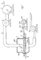
- numeral 1 is a mill, such as a hammer mill, receiving the cellulosic material from 2, said cellulosic material being disgregated into fibers which are entrained out of the mill suspended in a stream of air created by an exhauster 3, and such a suspension of fibers and air is fed through the conduit 4 into the formation head 5.
- the formation head 5 substantially comprises a casing 105 of rectangular configuration in plan view, closed at the bottom by a perforated screen 205 and having a number of openings 305 in the top wall for communication with the atmosphere.
- the numeral 6 indicates generally a frame which is mounted so as to slide on a horizontal plane parallel to the bottom 205 of the head 5. This frame extends into the interior of the head 5, and a set of mutually parallel rollers 7 provided with radial needles 107 are rotatably mounted on said frame.
- the shafts 205 of the rollers 7 are actuated by electric motors 307.
- An electric motor 407, through a belt 507, a crank 607 and a connecting rod 707, reciprocates said frame 6 in the direction of the arrow F of Figure 2.
- the numeral 8 indicates the web for the dry-formation of a sheet of paper S.
- Said web 8 is formed by a pervious endless web which is translated below the head 5 at a short distance from the bottom 205 of said head.
- a casing 9 Located below the web 8, opposite the head 5, is a casing 9 connected to a vacuum source 10.
- the fibers passed through the perforated bottom 205 of the casing 5 will be deposited in the form of a layer S onto the web 8 due to the: action of the vacuum in the casing 9.
- the continuous cleaning of the sieve ensures a better distribution of the fibers on the formation web 8 either in the longitudinal and transverse directions, thus obtaining a final product S which is highly homogeneous, free from side fringes having different thickness and substance and which must be cut off with resulting loss of productivity.
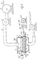
- FIGS 3 and 4 show a modified embodiment of the plant according to the invention.
- the same reference numerals have been used to indicate parts which are equal or corresponding to those shown in Figures 1 and 2.
- this embodiment differs from the preceding embodiment because within the head 5, above the set of rollers 7, there are mounted a second set of rollers 7' whose axes are perpendicular to the axes of the rollers 7, and which are rotatably supported by a frame 6' reciprocatingly movable in a plane parallel to the plane of the frame 6, in a direction which is perpendicular to that of the frame 6 (direction of the arrow F).
- the frame 6' is reciprocated by a motor 407' through the drive mechanism 507', 607', 70?'.
- the rollers 7' are actuated by the motors 307' through the shafts 207' of the rollers 7'.
- an intermediate sieve 405 Arranged below the rollers 7' is an intermediate sieve 405, similar to the sieve 205. The operation of the embodiment just described and illustrated is apparent.
- the fibers fed from the conduit 4 are subjected to a first screening and a first grading at the sieve 405 by the action of the rollers 7', and are then fed to the underlying sieve 205, which co-operates with the rollers 5, and are then fed onto the web 8 for the formation of a sheet S.
- the layer of fibers S after a suitable compaction, is submitted, in a manner known per se, to a binding step by means of a suitable adhesive binder, and a compaction step by means of calendering cylinders having either a smooth or an embossed surface (not shown).
- 5 is the distributing head, comprising the casing 105 of rectangular configuration in plan view, closed at the bottom by the perforated screen 205, and provided with a number of openings 305 in its top wall, for communication with the atmosphere.
- the conduit is shown for feeding a flow of air-fluidized disintegrated cellulosic fibers inside of the casing 5, whilst with numeral 8 the web is shown, onto which the screened fibers are deposited in a thin layer, for the formation of the dry paper sheet S.
- a suction casing is denoted, which is connected to a suitable vacuum surce (not shown).
- Each neddle-equipped roller, or at least some of them, are partially covered by a shielding or capping element 18, best shown in Figure 8, for the purposes which will be described later.
- the said shielding element 18 extends peripherally around each roller 7 by an angle ⁇ which is equal to 270° being an angle comprised between 0° and 90 0 , extending from the tangency point of the roller 7 with the bottom 205 in a direction opposite to the direction F of rotation of the roller 7, R being the radius of the needle-equipped roller.
- the said shielding element prevents furthermore the distorsion of the air flow due to the quick rotation of the rollers 7, as shown diagrammatically in Figure 7, which would entrain a non-homogeneous distribution of the fibers on the underlying formation web.
- rollers 7 are translated by the driwing chains 15, 15'.
- the pinions 16 are brought into mesh with the rack bars 17, thus imparting to said rollers 7 a rotational movement about their shafts 207.
- endless belts 19 may also be formed by trapezoidal belts, in which instance the pinions 16 will be substituted by pulleys.
Abstract
Description
- This invention relates to a method for the dry-forming of paper, of the kind in which cellulose fibers suspended in a stream of air are deposited onto an air-pervious web under the action of vacuum, thus forming a layer of fibers; the thus formed layer of fibers being then suitably pressed and compacted by means also of a suitable adhesive binder.
- More particularly, this invention relates to an apparatus or head for depositing the fibers onto said web for the formation of the layer of fibers.
- Some types of heads for depositing the fibers onto a formation web are known. Thus, for example, in the U.S. Patent No. 3.581.706 filed on November 13, 1969 and granted on June 1, 1971 to Mr. Karl Kristian Kobs Kroyer there is shown and described a formation head of the type disclosed above, comprising a cylindrical housing provided with a bottom flat perforated wall, with an inlet opening for a stream of air having fibers suspended therein, and provided in the interior thereof with a stirrer comprising one or more rotating stirring blades suspended at a short distance from said bottom wall, so mounted as to perform - together with the rotary motion about their axis - a circular translatory movement around the axis of the formation head.
- One of the disadvantages of this formation head resides in the fact that due to the movement of the stirrers parallelly to the bottom wall, said bottom wall is liable to become clogged. Moreover, the planetary movement of the stirrers implies the arrangement, in the interior of the head, of very delicate drive members liable to be damaged or broken.
- The European Patent Application No. 812000586 filed on January 16, 1981 in the name of Scanweb I/S discloses a formation head comprising two cylindrical parallel perforated chambers, each provided in the interior thereof with a cylinder having radial needles thereon and tangent to one of the directrices of said chambers. Each chamber rotates around its axis, and the cylinder associated therewith rotates in the opposite direction around its axis. The fiber-entraining stream of air is fed into the interior of said cylindrical chambers, and the fibers outflowing from said cylindrical chambers are deposited onto the underlying formation web.
- This formation head is relatively complicated and each head requires at least two distributing chambers and, nevertheless, the distribution onto the underlying cloth is scarcely uniform.
- The U.S. Patent No. 4.157.724 filed on December 19, 1977 and granted on June 12, 1979 to Torsten B. Persson discloses a formation head substantially comprising a V-shaped reticulated bottom extending transversely to the formation web. Mounted within said container are stirrers; for stirring the fibers being fed into said.container so as to hurl them against said reticulated bottom and move them therealong to pass through the network thereof and deposit them onto the formation cloth. According to this formation head, said reticulated bottom extends laterally upwards to permit said stirrers to operate as well at the periphery of the network. However, this creates problems of uniform distribution. Moreover, due to the inherent mode of operation of this head, the fibers are separated from the fiber-entraining stream of air before being fed into the head.
- This invention aims to overcome the disadvantages of the heretofore known formation heads, by providing a new formation head in high-productivity installations for the dry-production of paper, said new head ensuring the deposition of a more uniform and homogeneous layer than those heretofore obtainable with any conventional formation head.
- According to a feature of the invention, this object is achieved by mounting within the formation head, close to the perforated bottom wall thereof, a set of needle-equipped rollers rotatably supported around their axes and movable parallelly to the bottom of the formation head.
- Advantageously, said rotatable rollers are arranged transversely to the direction of advance of the underlying fiber-carrying web and are rotated by one or more motors while translated parallelly to the bottom of the head.
- By virtue of the arrangement described above, the following advantages are obtained:
- (a)- The rotary-translatory movement of the needle-equipped rollers located above the perforated bottom of the formation head ensures a better casual distribution of the fibers, thus improving their spatial distribution. Such a distribution enables the production of paper having a higher specific volume permitting to improve the bond between fibers and resin and enables the production of paper having geater softness and larger thickness, and therefore higher absorption capacity.
- (b)- The continuous cleaning of the planar perforated bottom or sieve ensures, in comparison with a head having the same area and vacuum, a greater specific outflowing capacity (expressed in Kg/m2) of the heterogeneous mixture air/fibers and, therefore, a greater productivity at a parity of the other parameters (such as speed of advance of the formation web, flowrate of air, area of the formation head, etc.).
- (c)- The continuous cleaning of the sieve ensures a better distribution of fibers on the formation web either in the longitudinal and in the transverse directions, thus avoiding the formation of side fringes having different thickness and substance, which are found in the paper produced by the formation heads described previously,and which must be cut off, with resulting loss of productivity.
- (d)- The absence of recirculation permits to preserve the quality of the fibers (under the dimensional aspect) which will not be submitted to any further grinding in the mill.
- According to a first embodiment of the invention, the said needle-equipped rollers or cylinders are rotatably supported around their axis, above the bottom screen of the formation head, and are provided with an alternative to and fro movement in a plane parallel to the plane of said screen.
- It has been however discovered that with the above mentioned arrangement there is a certain tendency to the accumulation of cellulosic aggregates between the needle-equiped rollers. It has been also noted that the said aggregates tends to increase in dimensions and in quantity during the time by effect of the alternative movement of the needle-equiped rollers, which facilitates a compaction between said agglomerates and the cellulosic fibers.
- According to a further feature of the invention, it has been noted that it is possible to obviate to the above drawbacks by conferring to the needle-equipped rollers an unidirectional roto-translative motion.
- According to one embodiment of the invention, the above is obtained by supporting the needle-equipped rollers between a pair of endless chains which are driven by suitable motor-operated chain wheels.
- It has been further noted a certain tendency of the ground cellulose to be compressed against the screening net, with following formation of agglomerates and with the consequent forced passage of cellulosic agglomerates through the screening net, with the result that the quality of the final product is negatively influenced.
- According to a still further embodiment of the invention, the above described drawback is obviated by associating with each needle-equipped roller a fixed capping or shielding element which screens at least that portion of the surface of the roller which is disposed upstream of the zone of contact between the needle-equipped cylinder and the screening net, in the direction of rotation of the said roller.
- Thanks to the presence of the said shielding element, also the distorsion of the air flow and of the entrained ground cellulose is obviated, thus reducing the ventilation effect caused by the rotation of the needle-equipped rollers.
- Further characteristics and advantages of the present invention will become evident form the following description of some preferred embodiments of same, made with reference to the accompanying drawings, in which:
- Figure 1 is a diagrammatic elevational and partly sectional view of a plant for the dry-production of paper according to the invention;
- Figure 2 is a plan and partly sectional view, on a larger scale, of the formation head of the plant shown in Figure 1;
- Figure 3 is a diagrammatic view similar to Figure 1, of a modified embodiment of a plant for the dry-production of paper according to the invention.
- Figure 4 is a plan and partly sectional view of the formation head of the modified embodiment shown in Figure 3.
- Figure 5 is a diagrammatic elevational and partly sectioned view, of a formation head according to another embodiment of the invention.
- Figure 6 is a top plan view, partly sectioned, of the formation head according to Figure 5.
- Figure 7 is a diagrammatic end view of a needle-equipped roller used in the formation heads according to the invention.
- Figure 8 shows the same cylinder of Figure 7, provided with the capping or shielding element according to a further embodiment of the invention, and
- Figure 9 shows a particular of a still further embodiment of a driving device for the needle-equipped rollers used in the formation head shown in Figure 5.
- With reference to the drawings, and particularly with reference to Figures 1 and 2 thereof,
numeral 1 is a mill, such as a hammer mill, receiving the cellulosic material from 2, said cellulosic material being disgregated into fibers which are entrained out of the mill suspended in a stream of air created by anexhauster 3, and such a suspension of fibers and air is fed through the conduit 4 into theformation head 5. - The
formation head 5 substantially comprises acasing 105 of rectangular configuration in plan view, closed at the bottom by aperforated screen 205 and having a number ofopenings 305 in the top wall for communication with the atmosphere. - The
numeral 6 indicates generally a frame which is mounted so as to slide on a horizontal plane parallel to thebottom 205 of thehead 5. This frame extends into the interior of thehead 5, and a set of mutuallyparallel rollers 7 provided withradial needles 107 are rotatably mounted on said frame. Theshafts 205 of therollers 7 are actuated byelectric motors 307. Anelectric motor 407, through abelt 507, acrank 607 and a connectingrod 707, reciprocates saidframe 6 in the direction of the arrow F of Figure 2. - The
numeral 8 indicates the web for the dry-formation of a sheet of paper S. Saidweb 8 is formed by a pervious endless web which is translated below thehead 5 at a short distance from thebottom 205 of said head. Located below theweb 8, opposite thehead 5, is acasing 9 connected to a vacuum source 10. In a manner known per se, the fibers passed through theperforated bottom 205 of thecasing 5 will be deposited in the form of a layer S onto theweb 8 due to the: action of the vacuum in thecasing 9. - The operation of the plant described above is apparent. Due to the rotary-translatory movement of the needle-equipped
rollers 7 located above thebottom sieve 205 of thehead 5, an optimum casual distribution, and thus a better spatial distribution, of the fibers is obtained. This distribution enables the production of paper S having a higher specific volume, greater softness, larger thickness and, therefore, higher absorption capacity. - By virtue of the continuous cleaning of the
flat bottom sieve 205, it will be possible to obtain, in comparison with a formation head having the same area and vacuum, a greater specific outflowing capacity of the heterogeneous mixture of air and fibers, thus achieving a greater productivity at a parity of the other parameters (speed of advance of theweb 8, flowrate of air,surface 205 of the formation head) which was not possible heretofore with the conventional installations. - Finally, the continuous cleaning of the sieve ensures a better distribution of the fibers on the
formation web 8 either in the longitudinal and transverse directions, thus obtaining a final product S which is highly homogeneous, free from side fringes having different thickness and substance and which must be cut off with resulting loss of productivity. - Figures 3 and 4 show a modified embodiment of the plant according to the invention. In the illustrated embodiment, the same reference numerals have been used to indicate parts which are equal or corresponding to those shown in Figures 1 and 2.
- As shown, this embodiment differs from the preceding embodiment because within the
head 5, above the set ofrollers 7, there are mounted a second set of rollers 7' whose axes are perpendicular to the axes of therollers 7, and which are rotatably supported by a frame 6' reciprocatingly movable in a plane parallel to the plane of theframe 6, in a direction which is perpendicular to that of the frame 6 (direction of the arrow F). The frame 6' is reciprocated by a motor 407' through the drive mechanism 507', 607', 70?'. The rollers 7' are actuated by the motors 307' through the shafts 207' of the rollers 7'. - Arranged below the rollers 7' is an
intermediate sieve 405, similar to thesieve 205. The operation of the embodiment just described and illustrated is apparent. The fibers fed from the conduit 4 are subjected to a first screening and a first grading at thesieve 405 by the action of the rollers 7', and are then fed to theunderlying sieve 205, which co-operates with therollers 5, and are then fed onto theweb 8 for the formation of a sheet S. - Of course, the layer of fibers S, after a suitable compaction, is submitted, in a manner known per se, to a binding step by means of a suitable adhesive binder, and a compaction step by means of calendering cylinders having either a smooth or an embossed surface (not shown).
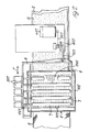
- With reference to the embodiment of the invention shown in Figures 5 and 6 of the drawings, 5 is the distributing head, comprising the
casing 105 of rectangular configuration in plan view, closed at the bottom by theperforated screen 205, and provided with a number ofopenings 305 in its top wall, for communication with the atmosphere. With numeral 4 the conduit is shown for feeding a flow of air-fluidized disintegrated cellulosic fibers inside of thecasing 5, whilst withnumeral 8 the web is shown, onto which the screened fibers are deposited in a thin layer, for the formation of the dry paper sheet S. With 9 a suction casing is denoted, which is connected to a suitable vacuum surce (not shown).
With 11 and 111 two shafts are shown, extending transversally across thecasing 105, and suitably journalled at their ends. Theshaft 11 is connected to asuitable driving motor 12, whilst theshaft 111 is idle supported. At both ends of theshafts chain wheels chains 15, 15' are guided. To the saidchains 15, 15' theshafts 207 of the needle-equippedrollers 7 are idle suspended. To the ends of saidshafts 207 thepinions 16 are secured, which pinions may be brought into mesh with the rack bars 17, which are secured to thecasing 105 both parallelly to the bottom 205 and parallelly to the upper wall of said casing. - Each neddle-equipped roller, or at least some of them, are partially covered by a shielding or capping
element 18, best shown in Figure 8, for the purposes which will be described later. - The said shielding
element 18 extends peripherally around eachroller 7 by an angle β which is equal to 270° being an angle comprised between 0° and 900, extending from the tangency point of theroller 7 with the bottom 205 in a direction opposite to the direction F of rotation of theroller 7, R being the radius of the needle-equipped roller. - The said shielding
element 18, which covers also the heads of theroller 7, forms an adjustable capping element preveting the accumulation of agglomerates in the tangency zone between therollers 7 and theperforated screen 205, with following extrusion of said agglomerates through the perforations of the screen. - The said shielding element prevents furthermore the distorsion of the air flow due to the quick rotation of the
rollers 7, as shown diagrammatically in Figure 7, which would entrain a non-homogeneous distribution of the fibers on the underlying formation web. - The operation of the described device will be evident. The
rollers 7 are translated by thedriwing chains 15, 15'. During the motion of therollers 7, thepinions 16 are brought into mesh with the rack bars 17, thus imparting to said rollers 7 a rotational movement about theirshafts 207. - In Figure 9 a still further embodiment of the invention is shown, according to which the rack bars have been substituted by the
toothed belts 19, which are driven by thewheels 20, 20', thewheel 20 being driven by a suitable motor (not shown). - Of course, the
endless belts 19 may also be formed by trapezoidal belts, in which instance thepinions 16 will be substituted by pulleys. - Of course, the present invention is not limited to the embodiments shown and described, which are intended to be only non limiting examples, and it is to be understood that changes may be made to the described embodiments without departing from the spirit of the invention, as claimed in the appended claims.
Claims (10)
Priority Applications (1)
| Application Number | Priority Date | Filing Date | Title |
|---|---|---|---|
| AT85104333T ATE31758T1 (en) | 1984-04-27 | 1985-04-10 | DEVICE FOR UNIFORM DISTRIBUTION OF A PARTED FIBER MATERIAL ONTO A FIBER LAYER FORMING AREA IN PLANTS FOR THE DRY FORMING OF PAPER. |
Applications Claiming Priority (4)
| Application Number | Priority Date | Filing Date | Title |
|---|---|---|---|
| IT12501/84A IT1180751B (en) | 1984-04-27 | 1984-04-27 | DISTRIBUTOR HEAD FOR THE UNIFORM DEPOSITION OF DISINTEGRATED FIBROUS MATERIAL ON A FORMATION SURFACE OF A LAYER OF FIBERS IN PLANTS FOR THE PRODUCTION OF DRY PAPER |
| IT1250184 | 1984-04-27 | ||
| IT12402/85A IT1186804B (en) | 1985-01-08 | 1985-01-08 | Paper dry-forming appts. |
| IT1240285 | 1985-01-08 |
Publications (2)
| Publication Number | Publication Date |
|---|---|
| EP0159618A1 true EP0159618A1 (en) | 1985-10-30 |
| EP0159618B1 EP0159618B1 (en) | 1988-01-07 |
Family
ID=26326501
Family Applications (1)
| Application Number | Title | Priority Date | Filing Date |
|---|---|---|---|
| EP85104333A Expired EP0159618B1 (en) | 1984-04-27 | 1985-04-10 | Apparatus for uniformly distributing a disintegrated fibrous material on a fiber layer forming surface in plants for the dry forming of paper |
Country Status (3)
| Country | Link |
|---|---|
| US (1) | US4650409A (en) |
| EP (1) | EP0159618B1 (en) |
| DE (1) | DE3561337D1 (en) |
Cited By (9)
| Publication number | Priority date | Publication date | Assignee | Title |
|---|---|---|---|---|
| GB2247697A (en) * | 1990-09-07 | 1992-03-11 | Extrusion Systems Ltd | Improvements relating to apparatus for use in producing non-woven webs from thermo-plastic |
| WO1999036623A1 (en) * | 1997-12-23 | 1999-07-22 | Marianne Etlar Eriksen | Fiber distributor |
| WO2001026868A1 (en) * | 1999-10-14 | 2001-04-19 | Www.Ideandersen.Dk Aps | A fibreboard and a method of manufacturing it |
| WO2005044529A1 (en) * | 2003-11-07 | 2005-05-19 | Formfiber Denmark Aps | A fibre distribution device for dry forming a fibrous product |
| WO2005106091A1 (en) * | 2004-04-29 | 2005-11-10 | Concert Gmbh | Moulded head and method for the production of a nonwoven fabric |
| US7480966B2 (en) | 2003-07-02 | 2009-01-27 | A. Celli Nonwovens S.P.A. | Mixing device for a head for dry-forming paper and associated method |
| US7487573B2 (en) | 2002-10-15 | 2009-02-10 | A Celli Nonwovens S.P.A. | Device for dry forming a web of fibers |
| EP2078769A1 (en) * | 2008-01-11 | 2009-07-15 | Portico Ldt. | A forming head for dry forming a fibrous web |
| EP3660211A1 (en) * | 2018-11-30 | 2020-06-03 | Seiko Epson Corporation | Fibrous body accumulating apparatus and sheet manufacturing apparatus |
Families Citing this family (30)
| Publication number | Priority date | Publication date | Assignee | Title |
|---|---|---|---|---|
| DE3841276C1 (en) * | 1988-12-08 | 1990-05-17 | G. Siempelkamp Gmbh & Co, 4150 Krefeld, De | |
| DE4302360A1 (en) * | 1993-01-28 | 1994-08-04 | Zimmermann Wolfgang | Mixing devices for sieves |
| JP3509863B2 (en) * | 1993-05-26 | 2004-03-22 | テルソニック、アクチェンゲゼルシャフト | Apparatus and method for sieving, sorting, filtering, filtering or sizing substances |
| MXPA00006709A (en) * | 1998-01-07 | 2002-09-18 | Enviro Board Corp | Fiber panel manufacturing method and apparatus. |
| JP2002512316A (en) * | 1998-04-21 | 2002-04-23 | エム アンド ジェイ ファイバーテック アー/エス | Sieve net for fiber distributor |
| US6444214B1 (en) | 2000-05-04 | 2002-09-03 | Kimberly-Clark Worldwide, Inc. | Ion-sensitive, water-dispersible polymers, a method of making same and items using same |
| US6828014B2 (en) | 2001-03-22 | 2004-12-07 | Kimberly-Clark Worldwide, Inc. | Water-dispersible, cationic polymers, a method of making same and items using same |
| US20030032352A1 (en) * | 2001-03-22 | 2003-02-13 | Yihua Chang | Water-dispersible, cationic polymers, a method of making same and items using same |
| DE10122971A1 (en) * | 2001-05-11 | 2002-11-14 | Siempelkamp Gmbh & Co | Spreading material system for spreading spreading material, in particular wood chips, wood fibers or the like on a spreading belt conveyor |
| US7772138B2 (en) | 2002-05-21 | 2010-08-10 | Kimberly-Clark Worldwide, Inc. | Ion sensitive, water-dispersible polymers, a method of making same and items using same |
| US7157389B2 (en) * | 2002-09-20 | 2007-01-02 | Kimberly-Clark Worldwide, Inc. | Ion triggerable, cationic polymers, a method of making same and items using same |
| US6994865B2 (en) * | 2002-09-20 | 2006-02-07 | Kimberly-Clark Worldwide, Inc. | Ion triggerable, cationic polymers, a method of making same and items using same |
| US6960371B2 (en) * | 2002-09-20 | 2005-11-01 | Kimberly-Clark Worldwide, Inc. | Water-dispersible, cationic polymers, a method of making same and items using same |
| US7141519B2 (en) * | 2002-09-20 | 2006-11-28 | Kimberly-Clark Worldwide, Inc. | Ion triggerable, cationic polymers, a method of making same and items using same |
| US20040058600A1 (en) * | 2002-09-20 | 2004-03-25 | Bunyard W. Clayton | Water-dispersible, cationic polymers, a method of making same and items using same |
| US7101456B2 (en) * | 2002-09-20 | 2006-09-05 | Kimberly-Clark Worldwide, Inc. | Ion triggerable, cationic polymers, a method of making same and items using same |
| US20060003654A1 (en) * | 2004-06-30 | 2006-01-05 | Lostocco Michael R | Dispersible alcohol/cleaning wipes via topical or wet-end application of acrylamide or vinylamide/amine polymers |
| US20060070712A1 (en) * | 2004-10-01 | 2006-04-06 | Runge Troy M | Absorbent articles comprising thermoplastic resin pretreated fibers |
| US20060086472A1 (en) * | 2004-10-27 | 2006-04-27 | Kimberly-Clark Worldwide, Inc. | Soft durable paper product |
| WO2007028124A2 (en) * | 2005-09-01 | 2007-03-08 | Sellars Absorbent Materials, Inc. | Method and device for forming non-woven, dry-laid, creped material |
| US20070141936A1 (en) * | 2005-12-15 | 2007-06-21 | Bunyard William C | Dispersible wet wipes with improved dispensing |
| EP2298977A1 (en) * | 2009-09-17 | 2011-03-23 | The Procter & Gamble Company | Fiber air-laying process for fibrous structures suitable for use in absorbent articles |
| US8969652B2 (en) | 2010-09-21 | 2015-03-03 | The Procter & Gamble Company | Disposable absorbent article |
| SG190437A1 (en) | 2010-12-02 | 2013-07-31 | Procter & Gamble | Absorbent article having improved bonding |
| BR112014010909A2 (en) | 2011-11-09 | 2017-05-16 | Procter & Gamble | double core absorbent article |
| JP6252232B2 (en) * | 2014-02-21 | 2017-12-27 | セイコーエプソン株式会社 | Sheet manufacturing apparatus and sheet manufacturing method |
| JP6248690B2 (en) * | 2014-02-21 | 2017-12-20 | セイコーエプソン株式会社 | Sheet manufacturing apparatus and sheet manufacturing method |
| US10398610B2 (en) | 2014-05-13 | 2019-09-03 | The Procter & Gamble Company | Absorbent article with dual core |
| US11655572B2 (en) | 2018-12-17 | 2023-05-23 | The Procter & Gamble Company | Method and apparatus for relofting a nonwoven substrate |
| WO2020253927A1 (en) | 2019-06-20 | 2020-12-24 | Advance Nonwoven A/S | Dry forming plant and method for dry forming a fibrous tissue using such dry forming plant |
Citations (6)
| Publication number | Priority date | Publication date | Assignee | Title |
|---|---|---|---|---|
| DE1024429B (en) * | 1954-04-14 | 1958-02-13 | Heinrich Schaefer Dipl Ing | Distribution device, especially for fibrous, blocking bulk material |
| DE1100927B (en) * | 1958-03-04 | 1961-03-02 | Ind Companie Kleinewefers Kons | Method and device for aligning the chips of a chipboard for the production of chipboard |
| US3644078A (en) * | 1965-06-11 | 1972-02-22 | Honshu Paper Co Ltd | Apparatus for producing nonwoven fabrics |
| DE2637860B1 (en) * | 1976-08-23 | 1977-12-01 | Baehre & Greten | Spreader for wood chips in chipboard prodn. - comprising inclined sieves and movable scattering rolls above moving belt |
| US4268235A (en) * | 1979-12-21 | 1981-05-19 | American Can Company | Apparatus for the manufacture of fibrous webs |
| EP0032772A1 (en) * | 1980-01-18 | 1981-07-29 | Scanweb I/S | Apparatus for dry forming of paper or other sheet material of particles or fibres |
Family Cites Families (6)
| Publication number | Priority date | Publication date | Assignee | Title |
|---|---|---|---|---|
| GB422226A (en) * | 1933-08-14 | 1935-01-08 | Raccolta A G | Improvements relating to the production of laps, fleeces or the like of fibrous material and pads or the like made therefrom |
| US2269085A (en) * | 1940-02-16 | 1942-01-06 | Continental Gin Co | Cleaning condensable fiber |
| US2841154A (en) * | 1954-11-01 | 1958-07-01 | American Mach & Foundry | Cigarette machine feed |
| GB1516573A (en) * | 1976-04-02 | 1978-07-05 | Kroyer St Annes Ltd Karl | Dry-laying a web of particulate or fibrous material |
| US4112549A (en) * | 1977-09-19 | 1978-09-12 | Beloit Corporation | Apparatus for deflocculating fibrous wad and uniformly distributing the disintegrated fibrous material on a dry fiber layer forming surface |
| JPS55165116A (en) * | 1979-06-11 | 1980-12-23 | Ando Screen Seisakusho:Kk | Brush driving device of screen for solid-liquid separation |
-
1985
- 1985-04-10 DE DE8585104333T patent/DE3561337D1/en not_active Expired
- 1985-04-10 EP EP85104333A patent/EP0159618B1/en not_active Expired
- 1985-04-12 US US06/722,369 patent/US4650409A/en not_active Expired - Fee Related
Patent Citations (6)
| Publication number | Priority date | Publication date | Assignee | Title |
|---|---|---|---|---|
| DE1024429B (en) * | 1954-04-14 | 1958-02-13 | Heinrich Schaefer Dipl Ing | Distribution device, especially for fibrous, blocking bulk material |
| DE1100927B (en) * | 1958-03-04 | 1961-03-02 | Ind Companie Kleinewefers Kons | Method and device for aligning the chips of a chipboard for the production of chipboard |
| US3644078A (en) * | 1965-06-11 | 1972-02-22 | Honshu Paper Co Ltd | Apparatus for producing nonwoven fabrics |
| DE2637860B1 (en) * | 1976-08-23 | 1977-12-01 | Baehre & Greten | Spreader for wood chips in chipboard prodn. - comprising inclined sieves and movable scattering rolls above moving belt |
| US4268235A (en) * | 1979-12-21 | 1981-05-19 | American Can Company | Apparatus for the manufacture of fibrous webs |
| EP0032772A1 (en) * | 1980-01-18 | 1981-07-29 | Scanweb I/S | Apparatus for dry forming of paper or other sheet material of particles or fibres |
Cited By (20)
| Publication number | Priority date | Publication date | Assignee | Title |
|---|---|---|---|---|
| GB2247697A (en) * | 1990-09-07 | 1992-03-11 | Extrusion Systems Ltd | Improvements relating to apparatus for use in producing non-woven webs from thermo-plastic |
| WO1999036623A1 (en) * | 1997-12-23 | 1999-07-22 | Marianne Etlar Eriksen | Fiber distributor |
| WO1999036622A1 (en) * | 1997-12-23 | 1999-07-22 | Marianne Etlar Eriksen | Fibre distributor |
| US6233787B1 (en) | 1997-12-23 | 2001-05-22 | Marianne Etlar Eriksen | Fiber distributor |
| AU757141B2 (en) * | 1997-12-23 | 2003-02-06 | Carsten Andersen | Fiber distributor |
| CN1103839C (en) * | 1997-12-23 | 2003-03-26 | 玛丽安娜·埃特拉·埃里克森 | Fiber distributor |
| WO2001026868A1 (en) * | 1999-10-14 | 2001-04-19 | Www.Ideandersen.Dk Aps | A fibreboard and a method of manufacturing it |
| US6645593B1 (en) | 1999-10-14 | 2003-11-11 | Www.Ideandersen.Dk Aps | Fibreboard and a method of manufacturing it |
| US7487573B2 (en) | 2002-10-15 | 2009-02-10 | A Celli Nonwovens S.P.A. | Device for dry forming a web of fibers |
| US7480966B2 (en) | 2003-07-02 | 2009-01-27 | A. Celli Nonwovens S.P.A. | Mixing device for a head for dry-forming paper and associated method |
| CN100398283C (en) * | 2003-11-07 | 2008-07-02 | 福尔姆菲贝尔丹麦有限责任公司 | Fiber distribution device for dry forming a fibrous product and method |
| WO2005044529A1 (en) * | 2003-11-07 | 2005-05-19 | Formfiber Denmark Aps | A fibre distribution device for dry forming a fibrous product |
| US7491354B2 (en) | 2003-11-07 | 2009-02-17 | Formfiber Denmark Aps | Fiber distribution device for dry forming a fibrous product and method |
| WO2005106091A1 (en) * | 2004-04-29 | 2005-11-10 | Concert Gmbh | Moulded head and method for the production of a nonwoven fabric |
| US7690903B2 (en) | 2004-04-29 | 2010-04-06 | Concert Gmbh | Forming head and process for the production of a non-woven fabric |
| EP2078769A1 (en) * | 2008-01-11 | 2009-07-15 | Portico Ldt. | A forming head for dry forming a fibrous web |
| WO2009087236A1 (en) * | 2008-01-11 | 2009-07-16 | Portico.Ltd. | A forming head for dry forming a fibrous web |
| CN101925697B (en) * | 2008-01-11 | 2013-02-20 | 先进无纺股份公司 | Forming head for dry forming fibrous web |
| EP3660211A1 (en) * | 2018-11-30 | 2020-06-03 | Seiko Epson Corporation | Fibrous body accumulating apparatus and sheet manufacturing apparatus |
| US11214922B2 (en) | 2018-11-30 | 2022-01-04 | Seiko Epson Corporation | Fibrous material accumulating apparatus and sheet manufacturing apparatus |
Also Published As
| Publication number | Publication date |
|---|---|
| US4650409A (en) | 1987-03-17 |
| DE3561337D1 (en) | 1988-02-11 |
| EP0159618B1 (en) | 1988-01-07 |
Similar Documents
| Publication | Publication Date | Title |
|---|---|---|
| US4650409A (en) | Apparatus for uniformly distributing a disintegrated fibrous material on a fiber layer forming surface in plants for the dry forming of paper | |
| US4494278A (en) | Apparatus for the production of a fibrous web | |
| US4520530A (en) | Fiber feeding apparatus with a pivoted air exhaust wall portion | |
| US2635301A (en) | Web or mat forming device | |
| US4102963A (en) | Method of forming lignocellulosic fiber mats | |
| US2023273A (en) | Method and apparatus for making fibrous sheet material | |
| US2746096A (en) | Felting apparatus | |
| EP0194850B1 (en) | Apparatus for the production of fibrous webs including wood pulp | |
| SK279087B6 (en) | Device for continual manufacturing of web from mineral wool | |
| EP0006326B1 (en) | Apparatus for spreading fibres uniformly over a conveyor surface | |
| JP3178840B2 (en) | Method and apparatus for hydrodynamically producing deformable fiber mats having high tensile strength | |
| US2890493A (en) | Method and means for defibering materials | |
| RO119293B1 (en) | Installation for fractionating and scattering especially fibrous particles | |
| JPS60231828A (en) | Dry paper molding apparatus for uniformly dispersing ground fiber material on fiber layer forming surface | |
| CN213562772U (en) | Quantitative slicing device for processing traditional Chinese medicinal materials | |
| GB1224325A (en) | Apparatus for the production of fibrous sheet materials | |
| US4464225A (en) | Method and machine for fabricating building boards | |
| CN2292617Y (en) | Segregation distributor for oscillating riddle | |
| CN211254516U (en) | Automobile carpet production is with even stone device | |
| JP3048132B2 (en) | Method and apparatus for manufacturing felt fleece | |
| US3413688A (en) | Mat forming apparatus and method | |
| GB2085489A (en) | Method and apparatus for the preformation of a cushion | |
| US3966858A (en) | Linear apparatus and method for high speed production of air-laid non-woven webs | |
| SU644754A1 (en) | Device for making articles from fibrous masses | |
| US3003197A (en) | Mat forming apparatus |
Legal Events
| Date | Code | Title | Description |
|---|---|---|---|
| PUAI | Public reference made under article 153(3) epc to a published international application that has entered the european phase |
Free format text: ORIGINAL CODE: 0009012 |
|
| AK | Designated contracting states |
Designated state(s): AT BE CH DE FR GB IT LI LU NL SE |
|
| 17P | Request for examination filed |
Effective date: 19851008 |
|
| 17Q | First examination report despatched |
Effective date: 19860414 |
|
| GRAA | (expected) grant |
Free format text: ORIGINAL CODE: 0009210 |
|
| AK | Designated contracting states |
Kind code of ref document: B1 Designated state(s): AT BE CH DE FR GB IT LI LU NL SE |
|
| REF | Corresponds to: |
Ref document number: 31758 Country of ref document: AT Date of ref document: 19880115 Kind code of ref document: T |
|
| REF | Corresponds to: |
Ref document number: 3561337 Country of ref document: DE Date of ref document: 19880211 |
|
| ET | Fr: translation filed | ||
| ITF | It: translation for a ep patent filed |
Owner name: STUDIO INGG. FISCHETTI & WEBER |
|
| PLBE | No opposition filed within time limit |
Free format text: ORIGINAL CODE: 0009261 |
|
| STAA | Information on the status of an ep patent application or granted ep patent |
Free format text: STATUS: NO OPPOSITION FILED WITHIN TIME LIMIT |
|
| 26N | No opposition filed | ||
| ITPR | It: changes in ownership of a european patent |
Owner name: CESSIONE;UNIKAY DISPOSABLES S.R.L. |
|
| REG | Reference to a national code |
Ref country code: CH Ref legal event code: PUE Owner name: UNIKAY DISPOSABLES S.R.L. |
|
| REG | Reference to a national code |
Ref country code: FR Ref legal event code: TP |
|
| REG | Reference to a national code |
Ref country code: GB Ref legal event code: 732 |
|
| NLS | Nl: assignments of ep-patents |
Owner name: UNIKAY DISPOSABLES S.R.L. TE GENUA, ITALIE. |
|
| ITTA | It: last paid annual fee | ||
| PGFP | Annual fee paid to national office [announced via postgrant information from national office to epo] |
Ref country code: GB Payment date: 19940325 Year of fee payment: 10 |
|
| PGFP | Annual fee paid to national office [announced via postgrant information from national office to epo] |
Ref country code: FR Payment date: 19940328 Year of fee payment: 10 |
|
| PGFP | Annual fee paid to national office [announced via postgrant information from national office to epo] |
Ref country code: SE Payment date: 19940330 Year of fee payment: 10 |
|
| PGFP | Annual fee paid to national office [announced via postgrant information from national office to epo] |
Ref country code: LU Payment date: 19940331 Year of fee payment: 10 |
|
| PGFP | Annual fee paid to national office [announced via postgrant information from national office to epo] |
Ref country code: CH Payment date: 19940406 Year of fee payment: 10 Ref country code: BE Payment date: 19940406 Year of fee payment: 10 |
|
| PGFP | Annual fee paid to national office [announced via postgrant information from national office to epo] |
Ref country code: AT Payment date: 19940429 Year of fee payment: 10 |
|
| PGFP | Annual fee paid to national office [announced via postgrant information from national office to epo] |
Ref country code: NL Payment date: 19940430 Year of fee payment: 10 |
|
| EPTA | Lu: last paid annual fee | ||
| PGFP | Annual fee paid to national office [announced via postgrant information from national office to epo] |
Ref country code: DE Payment date: 19940627 Year of fee payment: 10 |
|
| EAL | Se: european patent in force in sweden |
Ref document number: 85104333.1 |
|
| PG25 | Lapsed in a contracting state [announced via postgrant information from national office to epo] |
Ref country code: LU Free format text: LAPSE BECAUSE OF NON-PAYMENT OF DUE FEES Effective date: 19950410 Ref country code: GB Effective date: 19950410 Ref country code: AT Effective date: 19950410 |
|
| PG25 | Lapsed in a contracting state [announced via postgrant information from national office to epo] |
Ref country code: SE Effective date: 19950411 |
|
| PG25 | Lapsed in a contracting state [announced via postgrant information from national office to epo] |
Ref country code: LI Effective date: 19950430 Ref country code: CH Effective date: 19950430 Ref country code: BE Effective date: 19950430 |
|
| BERE | Be: lapsed |
Owner name: UNIKAY DISPOSABLES S.R.L. Effective date: 19950430 |
|
| PG25 | Lapsed in a contracting state [announced via postgrant information from national office to epo] |
Ref country code: NL Effective date: 19951101 |
|
| GBPC | Gb: european patent ceased through non-payment of renewal fee |
Effective date: 19950410 |
|
| REG | Reference to a national code |
Ref country code: CH Ref legal event code: PL |
|
| PG25 | Lapsed in a contracting state [announced via postgrant information from national office to epo] |
Ref country code: FR Effective date: 19951229 |
|
| NLV4 | Nl: lapsed or anulled due to non-payment of the annual fee |
Effective date: 19951101 |
|
| PG25 | Lapsed in a contracting state [announced via postgrant information from national office to epo] |
Ref country code: DE Effective date: 19960103 |
|
| EUG | Se: european patent has lapsed |
Ref document number: 85104333.1 |
|
| REG | Reference to a national code |
Ref country code: FR Ref legal event code: ST |