EP0162680A2 - Electrical connectors - Google Patents
Electrical connectors Download PDFInfo
- Publication number
- EP0162680A2 EP0162680A2 EP85303507A EP85303507A EP0162680A2 EP 0162680 A2 EP0162680 A2 EP 0162680A2 EP 85303507 A EP85303507 A EP 85303507A EP 85303507 A EP85303507 A EP 85303507A EP 0162680 A2 EP0162680 A2 EP 0162680A2
- Authority
- EP
- European Patent Office
- Prior art keywords
- contact member
- hole
- contact
- contacts
- shoulder
- Prior art date
- Legal status (The legal status is an assumption and is not a legal conclusion. Google has not performed a legal analysis and makes no representation as to the accuracy of the status listed.)
- Withdrawn
Links
Images

Classifications
-
- H—ELECTRICITY
- H01—ELECTRIC ELEMENTS
- H01R—ELECTRICALLY-CONDUCTIVE CONNECTIONS; STRUCTURAL ASSOCIATIONS OF A PLURALITY OF MUTUALLY-INSULATED ELECTRICAL CONNECTING ELEMENTS; COUPLING DEVICES; CURRENT COLLECTORS
- H01R13/00—Details of coupling devices of the kinds covered by groups H01R12/70 or H01R24/00 - H01R33/00
- H01R13/40—Securing contact members in or to a base or case; Insulating of contact members
- H01R13/42—Securing in a demountable manner
- H01R13/426—Securing by a separate resilient retaining piece supported by base or case, e.g. collar or metal contact-retention clip
Definitions
- This invention relates to electrical connectors and more particularly to electrical connectors of the type comprising two mating bodies each consisting of a hollow body containing an insulator in which a plurality of elongate electrical contacts are located.
- the electrical contacts in one body are of the male type and the contacts in the other body are of the female type.
- the male contacts usually project from the insulator whilst the female contacts are usually wholly contained within the insulator. Wires are attached to the non-mating ends of the contacts.
- the other method is to provide a supporting clip inside each hole in a resilient insulator, the supporting clip having resilient projections or legs which engage suitable shoulders or grooves on the surface of the contact.
- the shoulders or projections formed in the holes in the insulator must be rigid enough to retain the contacts during normal use but resilient enough to allow insertion and removal of the contacts.
- the contacts may simply be forced into or out of the insulator or a shaped tool may be provided which can deform the resilient projections inside the hole to enable the contacts to be inserted and withdrawn more easily. Because the insulator material is fairly rigid however, these projections usually become worn after several replacement operations and no longer tightly hold the contacts in position. This method of retention therefore is only satisfactory when individual contacts need to be replaced a small number of times and the life of the connector can be fairly short.
- each supporting clip is usually located against one or more shoulders formed in the holes in the insulator and these shoulders also must be minimised in size.
- the shoulders are formed using core pins in the mould tool when the insulators are moulded, and it is difficult to obtain core pin profiles to provide sharp corners at the points of the shoulders.
- an electrical connector comprises a hollow body containing an insulating material having a plurality of holes formed therethrough, each hole comprising a central portion extending substantially the entire length of the hole and two end portions having smaller diameters than the central portion, a shoulder extending substantially perpendicularly to the axis of the hole at the junction of each end portion and the central portion, a supporting clip comprising an elongate tubular member adapted to be located in the central portion of each hole and to extend between the two shoulders, and an electrical contact member adapted to extend through the supporting clip, the contact member having an enlarged portion with a greater diameter than at least one of the end portions of the hole so that the end of the enlarged portion abuts one of the shoulders, the end of the enlarged portion of the contact member being urged against the shoulder by urging means formed on the supporting clip, the urging means contacting an abuttment formed on the contact member.
- the contact member comprises a hollow socket with an open end and a closed end, and preferably the open end of the hollow socket is urged against the shoulder.
- the abuttment formed on the contact member may comprise a circumferential groove around the contact member or it may comprise a shoulder formed around the contact member.
- the electrical connector shown in Figure 1 comprises two mating parts each comprising an insulator 10, 12 made of, for example, a semi-resilient polymer such as nylon contained within a metal housing 14, 16.
- the insulators have a number of holes 18, 20 therethrough in which are located contacts 22, 24, the contacts 22 being of the female or socket types and the contacts 24 being of the male or pin types.
- the pin contacts 24 enter the socket contacts 22 when the two parts of the connector are assembled together, the two parts being held together by a threaded locking sleeve 26 rotatably mounted on the housing 14 and adapted to engage a screw thread 28 or a bayonet coupling formed on the housing 16.
- Each socket contact 22 is located in its hole 18 by a shoulder 30 formed on the outside of the contact which is engaged by two or more inwardly projecting legs 32 of a supporting clip 34.
- the supporting clip comprises a split tube and is itself located in the insulator between two shoulders 36 and 38 in an enlarged portion of the hole 18.
- the supporting clip must be very thin and the shoulders must also be very small. Because of the very small size of the cores required to produce the holes during moulding of the insulator, these shoulders tend to have radiussed corners and the supporting clip can sometimes slip past the shoulders on insertion of the contact as shown in Figure 2. In this case the split supporting clip has been forced past the shoulder and collapsed inside the smaller diameter portion of the hole 18 resulting in the clip and the socket contact becoming jammed inside the insulator 10.
- the supporting clip 40 again consists of a split tube but extends completely to the open end of the socket contact 42.
- the hole 18 is substantially smaller in diameter, needing only to be of sufficient size to permit the pin contact to enter the socket contact.
- a much larger shoulder area is provided for the supporting clip and this shoulder is also conveniently used as an abuttment for the end of the socket contact.
- the socket contact is urged towards the shoulder by inwardly projecting tynes or legs 44 which engage a groove or shoulder formed in the contact adjacent to the other end of the socket portion of the contact.
- the supporting clip 40 is held in the elongate enlarged portion of the hole by a shoulder 46 formed adjacent to the other end of the hole 18. This shoulder may be moulded into the insulator 10 or a separate insulating portion 48 with a smaller diameter hole may be bonded to the insulator 10.
Abstract
Description
- This invention relates to electrical connectors and more particularly to electrical connectors of the type comprising two mating bodies each consisting of a hollow body containing an insulator in which a plurality of elongate electrical contacts are located. The electrical contacts in one body are of the male type and the contacts in the other body are of the female type. The male contacts usually project from the insulator whilst the female contacts are usually wholly contained within the insulator. Wires are attached to the non-mating ends of the contacts.
- Various arrangements are used to retain the contacts in the insulator in such connectors but in some cases it is desirable to be able to replace individual contacts which have been damaged during use without disturbing the other contacts. This is particularly desirable with connectors with a large number of contacts when the cost of replacing the complete connector would be very high.
- There are basically two methods of retaining the contacts in the insulator so that each contact can be removed and a new contact inserted without disturbing the remaining contacts. One method is to retain the contacts directly in a resilient insulator by shoulders or projections formed in the holes through the insulator which engage grooves or shoulders on the surfaces of the contacts.
- The other method is to provide a supporting clip inside each hole in a resilient insulator, the supporting clip having resilient projections or legs which engage suitable shoulders or grooves on the surface of the contact.
- With both of these methods it is important that the contacts are securely retained in the insulator, and are not dislodged during normal use of the connector assembly. Thus in the former method the shoulders or projections formed in the holes in the insulator must be rigid enough to retain the contacts during normal use but resilient enough to allow insertion and removal of the contacts. The contacts may simply be forced into or out of the insulator or a shaped tool may be provided which can deform the resilient projections inside the hole to enable the contacts to be inserted and withdrawn more easily. Because the insulator material is fairly rigid however, these projections usually become worn after several replacement operations and no longer tightly hold the contacts in position. This method of retention therefore is only satisfactory when individual contacts need to be replaced a small number of times and the life of the connector can be fairly short.
- For connectors which must have a longer life the supporting clip method is used, as the clip is designed to be deformed many times and the resilient insulator is not normally disturbed after the supporting clip is inserted into the hole. When there is a large number of contacts they are normally closely spaced with a minimum of insulator material around the holes and the thickness of the supporting clips must therefore be minimised. Each supporting clip is usually located against one or more shoulders formed in the holes in the insulator and these shoulders also must be minimised in size. The shoulders are formed using core pins in the mould tool when the insulators are moulded, and it is difficult to obtain core pin profiles to provide sharp corners at the points of the shoulders. One problem then is that the supporting clip can slip past a shoulder when a contact is inserted or removed, particularly if the clip is of split tube construction, resulting in the collapse and subsequent jamming of the clip and the contact in the insulator.
- It is an object of the present invention therefore to provide an electrical connector of the type having supporting clip retained contacts which will overcome or at least reduce the tendency for the supporting clips to be dislodged during insertion and removal of the contacts.
- According to the present invention an electrical connector comprises a hollow body containing an insulating material having a plurality of holes formed therethrough, each hole comprising a central portion extending substantially the entire length of the hole and two end portions having smaller diameters than the central portion, a shoulder extending substantially perpendicularly to the axis of the hole at the junction of each end portion and the central portion, a supporting clip comprising an elongate tubular member adapted to be located in the central portion of each hole and to extend between the two shoulders, and an electrical contact member adapted to extend through the supporting clip, the contact member having an enlarged portion with a greater diameter than at least one of the end portions of the hole so that the end of the enlarged portion abuts one of the shoulders, the end of the enlarged portion of the contact member being urged against the shoulder by urging means formed on the supporting clip, the urging means contacting an abuttment formed on the contact member.
- Preferably the contact member comprises a hollow socket with an open end and a closed end, and preferably the open end of the hollow socket is urged against the shoulder.
- The abuttment formed on the contact member may comprise a circumferential groove around the contact member or it may comprise a shoulder formed around the contact member.
- Embodiments of the invention will now be described by way of example only with reference to the accompanying drawings in which,
- Figure 1 is a partial cross-sectional view of two mating parts of a known type of electrical connector having contacts retained by supporting clips,
- Figure 2 is an enlarged view of part of Figure 1 showing a supporting clip in a dislodged position and,
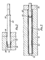
- Figure 3 is a cross-sectional view of part of an electrical connector according to the invention.
- The electrical connector shown in Figure 1 comprises two mating parts each comprising an
insulator metal housing 14, 16. The insulators have a number ofholes contacts contacts 22 being of the female or socket types and thecontacts 24 being of the male or pin types. Thepin contacts 24 enter thesocket contacts 22 when the two parts of the connector are assembled together, the two parts being held together by a threaded locking sleeve 26 rotatably mounted on the housing 14 and adapted to engage ascrew thread 28 or a bayonet coupling formed on thehousing 16. - Each
socket contact 22 is located in itshole 18 by ashoulder 30 formed on the outside of the contact which is engaged by two or more inwardly projectinglegs 32 of a supportingclip 34. The supporting clip comprises a split tube and is itself located in the insulator between twoshoulders hole 18. - If the connector contains a large number of small diameter contacts the supporting clip must be very thin and the shoulders must also be very small. Because of the very small size of the cores required to produce the holes during moulding of the insulator, these shoulders tend to have radiussed corners and the supporting clip can sometimes slip past the shoulders on insertion of the contact as shown in Figure 2. In this case the split supporting clip has been forced past the shoulder and collapsed inside the smaller diameter portion of the
hole 18 resulting in the clip and the socket contact becoming jammed inside theinsulator 10. - This occurrence is prevented in the present invention illustrated in Figure 3 in which the supporting
clip 40 again consists of a split tube but extends completely to the open end of thesocket contact 42. At this end thehole 18 is substantially smaller in diameter, needing only to be of sufficient size to permit the pin contact to enter the socket contact. Thus a much larger shoulder area is provided for the supporting clip and this shoulder is also conveniently used as an abuttment for the end of the socket contact. The socket contact is urged towards the shoulder by inwardly projecting tynes orlegs 44 which engage a groove or shoulder formed in the contact adjacent to the other end of the socket portion of the contact. - The supporting
clip 40 is held in the elongate enlarged portion of the hole by ashoulder 46 formed adjacent to the other end of thehole 18. This shoulder may be moulded into theinsulator 10 or a separateinsulating portion 48 with a smaller diameter hole may be bonded to theinsulator 10.
Claims (5)
Applications Claiming Priority (2)
| Application Number | Priority Date | Filing Date | Title |
|---|---|---|---|
| GB848413076A GB8413076D0 (en) | 1984-05-22 | 1984-05-22 | Electrical connectors |
| GB8413076 | 1984-05-22 |
Publications (2)
| Publication Number | Publication Date |
|---|---|
| EP0162680A2 true EP0162680A2 (en) | 1985-11-27 |
| EP0162680A3 EP0162680A3 (en) | 1988-08-17 |
Family
ID=10561339
Family Applications (1)
| Application Number | Title | Priority Date | Filing Date |
|---|---|---|---|
| EP85303507A Withdrawn EP0162680A3 (en) | 1984-05-22 | 1985-05-20 | Electrical connectors |
Country Status (3)
| Country | Link |
|---|---|
| EP (1) | EP0162680A3 (en) |
| JP (1) | JPS60254578A (en) |
| GB (2) | GB8413076D0 (en) |
Families Citing this family (2)
| Publication number | Priority date | Publication date | Assignee | Title |
|---|---|---|---|---|
| US4895529A (en) * | 1982-12-27 | 1990-01-23 | Amp Incorporated | Environmentally sealed connector |
| DE50009166D1 (en) * | 2000-08-08 | 2005-02-10 | Festo Ag & Co Kg | Control valve device and as part of the same suitable valve |
Citations (2)
| Publication number | Priority date | Publication date | Assignee | Title |
|---|---|---|---|---|
| US2419018A (en) * | 1942-01-03 | 1947-04-15 | Pauline E Wood | Connector |
| US3158424A (en) * | 1964-02-13 | 1964-11-24 | Itt | Contact mounting |
-
1984
- 1984-05-22 GB GB848413076A patent/GB8413076D0/en active Pending
-
1985
- 1985-05-17 GB GB08512560A patent/GB2159348B/en not_active Expired
- 1985-05-20 EP EP85303507A patent/EP0162680A3/en not_active Withdrawn
- 1985-05-22 JP JP60110057A patent/JPS60254578A/en active Pending
Patent Citations (2)
| Publication number | Priority date | Publication date | Assignee | Title |
|---|---|---|---|---|
| US2419018A (en) * | 1942-01-03 | 1947-04-15 | Pauline E Wood | Connector |
| US3158424A (en) * | 1964-02-13 | 1964-11-24 | Itt | Contact mounting |
Also Published As
| Publication number | Publication date |
|---|---|
| EP0162680A3 (en) | 1988-08-17 |
| GB8512560D0 (en) | 1985-06-19 |
| GB8413076D0 (en) | 1984-06-27 |
| JPS60254578A (en) | 1985-12-16 |
| GB2159348B (en) | 1988-01-20 |
| GB2159348A (en) | 1985-11-27 |
Similar Documents
| Publication | Publication Date | Title |
|---|---|---|
| US2419018A (en) | Connector | |
| US6729912B2 (en) | Audio signal connector | |
| US3221292A (en) | Electrical connector | |
| US3747047A (en) | Latchable integrally molded electrical connector | |
| US3120989A (en) | Electrical socket contact | |
| US4701004A (en) | Retention clip for electrical contacts | |
| US5720630A (en) | Electrical connector | |
| US8007319B2 (en) | Electrical connector contacts retained by releasable first and second inserts held by releasable first and second shells | |
| US6824427B1 (en) | Coaxial probe interconnection system | |
| US6074236A (en) | Guide post structure of electrical connector | |
| US4585366A (en) | Flexible connector | |
| US3323098A (en) | Sub-miniature coaxial connector | |
| US5364285A (en) | Waterproof connector | |
| US3031638A (en) | Connector assembly | |
| EP0162680A2 (en) | Electrical connectors | |
| US7270575B2 (en) | Circuit board and socket assembly | |
| US4810214A (en) | Electrical terminal and method of making same | |
| US4333703A (en) | Contact retention assembly | |
| US6872006B2 (en) | Fiber optic cable assembly | |
| US2659876A (en) | Indentable jack-type connector | |
| US4272150A (en) | Electrical contact for an electrical connector | |
| US3090937A (en) | Electrical connector with contact retention sleeve | |
| US4387943A (en) | Electrical connector having front or rear releasable and removable contacts | |
| US5624288A (en) | Field-replaceable socket for seismic connector | |
| US4772233A (en) | Low resistance connector |
Legal Events
| Date | Code | Title | Description |
|---|---|---|---|
| PUAI | Public reference made under article 153(3) epc to a published international application that has entered the european phase |
Free format text: ORIGINAL CODE: 0009012 |
|
| AK | Designated contracting states |
Designated state(s): AT BE CH DE FR IT LI LU NL SE |
|
| RAP1 | Party data changed (applicant data changed or rights of an application transferred) |
Owner name: AB ELECTRONIC COMPONENTS LIMITED |
|
| PUAL | Search report despatched |
Free format text: ORIGINAL CODE: 0009013 |
|
| AK | Designated contracting states |
Kind code of ref document: A3 Designated state(s): AT BE CH DE FR IT LI LU NL SE |
|
| STAA | Information on the status of an ep patent application or granted ep patent |
Free format text: STATUS: THE APPLICATION IS DEEMED TO BE WITHDRAWN |
|
| 18D | Application deemed to be withdrawn |
Effective date: 19890218 |
|
| RIN1 | Information on inventor provided before grant (corrected) |
Inventor name: OSBORNE, COLIN SYDNEY |