EP0165875A1 - Method of making microspheres from glass - Google Patents
Method of making microspheres from glass Download PDFInfo
- Publication number
- EP0165875A1 EP0165875A1 EP85401232A EP85401232A EP0165875A1 EP 0165875 A1 EP0165875 A1 EP 0165875A1 EP 85401232 A EP85401232 A EP 85401232A EP 85401232 A EP85401232 A EP 85401232A EP 0165875 A1 EP0165875 A1 EP 0165875A1
- Authority
- EP
- European Patent Office
- Prior art keywords
- particles
- burner
- microspheres
- air
- glass
- Prior art date
- Legal status (The legal status is an assumption and is not a legal conclusion. Google has not performed a legal analysis and makes no representation as to the accuracy of the status listed.)
- Granted
Links
Images


Classifications
-
- C—CHEMISTRY; METALLURGY
- C03—GLASS; MINERAL OR SLAG WOOL
- C03B—MANUFACTURE, SHAPING, OR SUPPLEMENTARY PROCESSES
- C03B19/00—Other methods of shaping glass
- C03B19/10—Forming beads
- C03B19/107—Forming hollow beads
- C03B19/1075—Forming hollow beads by blowing, pressing, centrifuging, rolling or dripping
-
- Y—GENERAL TAGGING OF NEW TECHNOLOGICAL DEVELOPMENTS; GENERAL TAGGING OF CROSS-SECTIONAL TECHNOLOGIES SPANNING OVER SEVERAL SECTIONS OF THE IPC; TECHNICAL SUBJECTS COVERED BY FORMER USPC CROSS-REFERENCE ART COLLECTIONS [XRACs] AND DIGESTS
- Y02—TECHNOLOGIES OR APPLICATIONS FOR MITIGATION OR ADAPTATION AGAINST CLIMATE CHANGE
- Y02P—CLIMATE CHANGE MITIGATION TECHNOLOGIES IN THE PRODUCTION OR PROCESSING OF GOODS
- Y02P40/00—Technologies relating to the processing of minerals
- Y02P40/50—Glass production, e.g. reusing waste heat during processing or shaping
- Y02P40/57—Improving the yield, e-g- reduction of reject rates
Definitions
- the invention relates to techniques for producing hollow glass microspheres, and more precisely to those techniques in which fine solid particles of an appropriate glass are expanded by heat treatment.
- a permanent difficulty specific to these techniques lies in obtaining a product having well-defined defined properties, in a minimum of simple operations.
- this type of operation is usually not very satisfactory in terms of its yield and the quality of the products obtained. .
- This is explained in particular by the difficulty of conducting the treatment in a perfectly uniform manner for all of the particles. A non-negligible part of the mass of the treated particles is not found in expanded form at the end of the treatment.
- An object of the invention is to propose a technique for producing microspheres from glass particles containing in particular sulfur compounds by a heat treatment, the yield of which is improved.
- Another object of the invention is to ensure that the technique in question can be carried out under advantageous cost conditions.
- Another object of the invention is to allow the use of a wider range of materials than previously.
- the invention aims to allow the treatment of glasses whose sulfur content is relatively low.
- the object of the invention is to allow the treatment of particles whose dimensions are possibly smaller than the particles previously treated.
- Another object of the invention is, by controlling the conditions under which the expansion of the particles is carried out, to lead to products whose properties are better controlled.
- the prior art teaches, in fact, that it is necessary to operate the expansion at a temperature much lower than that used during the melting of the raw materials for obtaining the vitreous mass of which the particles are made up.
- the traditional temperatures for production from traditional materials including in particular sand, lime, carbonate sodium, sodium sulfate are between 1250 and 1450 ° C.
- the prior art offers a treatment thermal expansion which is between 1050 and 1380 ° C. The expansion temperature is therefore 100 to 300 ° C lower than that of glass formation.
- the processing temperature is significantly higher than that of the raw materials.
- the expansion according to the invention is carried out at a temperature above 1500 ° C, and preferably above 1550 ° C, i.e. approximately a temperature which is at least 100 ° C higher. to that of glass making.
- the treatment temperature according to the invention is between 1550 and 1700 ° C.
- the treatment temperature can be maintained for an extremely short time. Given the size of the particles used, a treatment time of a few thousandths of a second is generally sufficient to obtain a good yield. A prolongation of the treatment proves most often ineffective in increasing the output.
- the residence time at the highest temperatures is not more than 0.1 seconds and preferably is less than 0.05 seconds.
- This processing time can be as small as 0.01 seconds or less.
- the treatment time can be very short.
- the treatment time will advantageously be no more than 0.02 seconds.
- the temperature must be brought to less than 1000 ° C and preferably to less than 750 ° C. These temperatures are reached practically immediately by introducing a sufficient quantity of air at ambient temperature into the reactor.
- the amount of air to freeze the microspheres is only limited by practical considerations.
- the volume of the ambient air is at least equal to twice that of the process gases carrying the spheres.
- the thermal decomposition usually envisaged transforms the sulfur compounds into sulfuric anhydride which is partly decomposed into sulfur dioxide according to the scheme:
- Sulfates are present in many industrial glasses. Their contents vary in very important proportions. In the glasses used for the formation of glazing, glasses which constitute a particularly important industrial application, the sulphates, by their capacity to decompose, play an important role in the refining during the production of the glassy mass. The release of SO 3 bubbles is an effective means of entraining the particles or gases occluded out of the molten mass. In these glasses, it goes without saying that the residual sulfate content is lower the more intense and longer the ripening. We will see later what consequences this entails with regard to the invention.
- the inventors have shown that in a reducing atmosphere and in particular in an atmosphere containing hydrogen, and preferably nascent hydrogen, oxidation-reduction phenomena intervene in the process of formation of the microspheres.
- a mechanism supposed includes as before the thermal decomposition followed by the reduction of sulfuric anhydride according to the following diagram: -,
- a first reason is related to the nature of the gas used for expansion. Indeed, at high temperature the sulfuric anhydride redissolves in the molten glass, and part of the microspheres thus undergoes a collapse before being frozen.
- the intensity of the reduction is not completely independent of the temperature.
- the reducing conditions normally result from the operation of a burner and the ratio of the quantity of fuel to the total quantity of gases used to produce combustion.
- the report in question leads to a reducing atmosphere when the combustible gas is in excess. We are therefore not at the stoichiometric conditions which make it possible to reach the highest flame temperatures.
- the equilibria which are established depend on the temperature conditions; the higher the temperature, the higher the formation of reducing agents, and in particular hydrogen.
- the temperature conditions and those of redox preferably, must be fixed jointly.
- Another advantage of the reducing treatment method according to the invention is to facilitate expansion even when the initial level of blowing agent, that is to say the content of sulfur compound in the glass, is relatively low. There is indeed a better "use” of this blowing agent.
- Analysis of the glass of the spheres produced in a reducing atmosphere shows a lower sulfur content than that of the spheres produced in an oxidizing atmosphere. This makes it possible, where appropriate, to use various sources to produce the particles which are expanded and in particular glass cullet poor in sulfur compounds, in particular cullet from glass having undergone extensive refining.
- the low sulfur content of well-refined glasses has for counterpart a better homogeneity of the glass which itself allows, all other things being equal, an improvement in the expansion yield and the obtaining of microspheres having particularly remarkable mechanical qualities.
- the implementation of the method according to the invention with these very refined glasses is therefore advantageous.
- the air factor that is to say the amount of air actually introduced into the burner relative to to that which would be necessary to have a neutral combustion.
- the treatment, and in particular the expansion yield is very sensitive to variations in this factor.
- the air factor, for the temperatures considered is not less than 0.75, and preferably is between 0.8 and 0.95.
- the reducing nature of the treatment atmosphere can also be defined by the content of reducing gases present, and in particular hydrogen, this gas as shown by the studies of the inventors being the most likely reducing agent taking into account in particular its rapidity to diffuse in the molten glass.
- the reducing treatment leading to the expansion of the microspheres is therefore preferably limited to conditions which do not substantially modify their properties.
- a hydrogen content of less than 4% in the treatment gases makes it possible to achieve a good expansion yield without modifying the quality of the microspheres obtained.
- this rate is less than 3%.
- this hydrogen rate is an overall rate measured on all of the combustion gases. This rate is only indicative of the reducing nature in the atmosphere immediately surrounding the particles insofar as these serve as "catalysts" on which hydrogen is formed.
- the reducing nature of the combustion also depends, to a certain extent, on the nature of the combustible gas chosen. It may be advantageous to choose a gas whose cracking is relatively intense under the conditions of the invention. Thus, the use of propane as a combustion gas may be preferred to that of methane insofar as the former leads to a more abundant evolution of hydrogen.
- the reducing nature may only be developed during part of the treatment. Given the mechanisms involved, it may appear advantageous to limit the reduction effect at the start of treatment.
- the sulfur compounds are transformed into sulfur dioxide insoluble in glass. This transformation being carried out, it goes without saying that the surrounding atmosphere can become neutral again or even slightly oxidizing for the end of the treatment.
- the treatment is usually carried out in the flame of a burner.
- the succession of reducing and neutral or even slightly oxidizing steps is obtained, for example, by advancing the particles through the flame from an area initially rich in combustible gas in areas where the gas mixture becomes stoichiometric or even slightly richer in air.
- the treatment benefits from the advantages linked to the reducing conditions.
- the succession of these stages does not actually intervene in the microsphere development process except because of the extreme rapidity of the phenomena involved, in particular the diffusion of hydrogen in the glass particles.
- the main composition of the glasses most commonly used for traditional applications is, for the main elements, of the following type:
- Oxygenated sulfur compounds are also present in these glasses. Their content can be very widely variable. Generally the sulfur content of the glasses does not exceed 0.5% by weight of the particles before their expansion, but much lower contents are sufficient to ensure an expansion leading to microspheres with a density as low as 0.1 g / cm3.
- the initial content. in sulfur can influence the degree of expansion reached, it constitutes a limit only for the production of highly expanded microspheres. This is the case for example when operating from particles containing very small amounts of sulfur, for example less than 0.01%.
- the microspheres produced then generally have a higher density. Far from being a disadvantage, this last characteristic can be sought. This is particularly the case when the microspheres are intended for uses for which resistance to very high hydrostatic pressure is necessary. There is indeed a very clear correlation between the density of the microspheres and this resistance to pressure. The higher the density, the higher the resistance.
- the glass particles used to produce microspheres have dimensions of less than 100 micrometers for the larger ones.
- larger particles can be expanded, their treatment is usually made more delicate for the reason that being more massive, the treatment time is necessarily longer which is not desirable as we indicated above.
- microspheres are obtained which can have a wide variety of dimensions, densities, glass compositions.
- the starting conditions are of course crucial.
- the initial particle size largely determines the final dimensions even if the nature of the glass and the treatment also play important roles.
- a particular feature of the methods according to the invention is that it allows the production of microspheres from smaller particles, the microspheres produced being themselves smaller. It is possible by the treatments according to the invention to produce, with satisfactory yield, microspheres whose average diameters are of the order of 5 micrometers in particular with higher densities.
- the microspheres produced have diameters between 20 and 100 micrometers.
- the largest microspheres ordinarily produced do not exceed 200 micrometers.
- the density of the microspheres produced is between 0.1 and 2.2 g / cm3.
- This density can be controlled to a certain extent by choosing the sulfur content of the particles, their dimensions and the characteristics of the treatment itself.
- the density is lower the higher the amount of sulfur and the treatment thermal is conducted at higher temperature.
- the percentage of expanded particles determined by flotation, is most often greater than 50% and is usually around 55 and more. For fractions having undergone a more rigorous initial particle size sorting, the percentage can reach and even exceed 65%.
- volume percentage although this value is not very significant since it depends on the expansion rate or what is equivalent to the average density. Under the conditions of the invention, if we consider the volume of expanded particles relative to the overall volume of the treated product, the yield usually exceeds 90% and can even exceed 95%.
- Another advantageous characteristic of the techniques according to the invention linked both to the high temperature and to the reducing action established at least during part of the treatment, is the low energy consumption for producing these microspheres. This consumption varies according to many parameters but is established on average at values of the order of ten therms per kg of treated particles or less.
- the increase in the processing temperature should in principle result in an increase in energy consumption. In fact, this increase is very small or nonexistent in the conditions of the invention. But above all, this consumption is particularly low when it is related to the expanded product and no longer to the initial product, given the high rate of expansion.
- a composition of 900 kg of glass is prepared in a pot at the melting temperature of 1250 ° C.
- the fusion time is 18 hours.
- the molten materials are as follows:
- the mass is melted in an oxidizing atmosphere. After being poured and cooled, the glass is crushed into fragments of a few centimeters and then in a second grinder into particles of a few millimeters.
- a final grinding in a ball mill leads the powder to a particle size less than 100 micrometers.
- Sorting using a dynamic selector makes it possible to isolate a still relatively large fraction of particles whose dimensions are, for this test, between 7 and 50 micrometers and corresponds to 80% by weight of the particles leaving the last mill.
- the chemical analysis by weight of the composition of the particles is as follows:
- the oxidized nature of the composition is analyzed by measuring the ratio (Fe3 + / Fe2 +) 2 according to the method developed by JL BARTON, JJ MASSOL and MH CHOPINET (XIII International Glass Congress Hamburg 1983 - Glasstechnische Berichte 56, 1983). In the case of this preparation, the ratio is greater than 280.
- the particles are suspended in an air stream at the rate of 6 kg of particles per hour at an air flow rate of 4.6 m3 / h.
- the injection speed into the burner in the axial position and at the bottom of the burner is 20 m / s.
- the cylindrical burner of the type described in patent publication FR-A-2 249 585 is supplied with Lacq gas (methane) and with air. Air injections are made tangentially. The gas is introduced first. Air is injected on the walls of the combustion chamber at two levels in the direction of gas progression. The air supply orifices are oriented so that the direction of rotation of the gases, for the two levels, are opposite each other. This arrangement while organizing intense mixing avoids communicating to the assembly a rotational movement which would lead to projecting the particles onto the walls of the burner.
- a cylindrical chamber 100 mm long follows the part of the burner in which the supply takes place. In this room the temperature reaches its maximum. It is immediately extended by a quenching chamber at the top of which the ambient air penetrates.
- the whole of this device is mounted vertically, the burner and the particle injection being located at the top so that the circulation takes place from top to bottom.
- Temperatures are measured by thermocouples. The contents of C0, C0 2 and 0 2 in the gases emitted by the burner are also measured.
- the particles introduced have the same particle size. It is a mixture whose dimensions for 80% by weight of the particles are between 7 and 50 micrometers.
- the feed is done at the rate of 6 kg / h of particle in the burner set for these tests at 125 therms / hour.
- the yield is expressed as a percentage by weight of expanded particles relative to the total mass recovered.
- the expanded particles are sorted by flotation.
- n a is the air factor.
- the inventors investigated the influence of variations in the redox conditions in the combustion gas on the yield of microspheres. Under conditions as close as possible to the other factors, they varied the proportions of air and fuel in the burner.
- the starting particles are the same as those used in Example 1.
- the particle size and the feed rate are also identical and the burner operates at 125 therms / hour.
- the inventors Independently of the influence on production, the inventors have verified the importance of redox phenomena in the formation of microspheres by analyzing for example the content of the gases occluded in these microspheres.
- the oxygen content varies very significantly.
- significant amounts of oxygen are detected and significantly lower amounts in a reducing atmosphere.
- the oxygen content is 3.7% and 9.3% by volume, respectively. This difference is due to the reduction by the hydrogen created in the flame.
- the reducing action of the atmosphere is also highlighted by the analysis of the glass of the initial particles and that of the glass forming the walls of the microspheres.
- the more or less oxidized character can be determined by the ratio (Fe3 + ) 2 / (Fe2 +) 2 of the glass. For the tests considered 2 and 3, this ratio is 2.1 and 5.8 respectively.
- Test n ° 1 reproduced with this particle size, the other parameters being unchanged, results in a yield of 64% by weight of expanded particles (more than 95% by volume).
- Tests have been carried out to demonstrate the existence of the different stages of the physico-chemical process followed by the particles subjected to either reducing or oxidizing conditions, or combining these two types.
- the particles, in a first test, are introduced at the bottom of the burner and therefore pass through the flame, that is to say the relatively reducing zone of the flame front, then the zone located downstream of this flame front and which is less reducing or even neutral or oxidizing depending on the value of the air factor.
- the treatment temperature is 1550 ° C and the air factor of 1.1. Complete combustion is therefore oxidizing.
- the gaseous content of the microspheres introduced at the bottom of the burner shows an S0 2 content of 90.9% and in O 2 of 5.8%.
- the other gases detected are CO 2 and 2, the water vapor is not not measured the analysis being made by mass spectrography.
- the particles are introduced about ten centimeters downstream from the flame front.
- the gas mixture used this time is slightly reducing (air factor 0.92).
- the fraction chosen is between 8 and 15 micrometers.
- the processing temperature is 1600 ° C.
- the yield by weight of expanded particles relative to the treated material is 48% and the density of these particles is 0.3 g / cm3 on the part selected by flotation.
- the yield obtained is 59% and the density of the microspheres separated by flotation is 0.24 g / cm3.
- the glass is a float glass cullet with the following weight composition:
- the particles used have dimensions between 7 and 50 micrometers.
- the test was conducted at 1600 ° C and with an air factor of 0.9.
- the yield although lower than previously, remains interesting in practice. It is around 25% by weight.
- the density of the expanded particles is also high and around 0.35 g / cm3.
- the expansion of the particles by the combustion gases is advantageously carried out by circulating the particles from top to bottom in the same direction as the combustion gases.
- the supply of the device in which the expansion takes place, a burner or an enclosure in direct communication with the burner, causes the particles to circulate in the same direction as the flow of combustion gases. and from top to bottom.
- the device for producing the microspheres comprises the following elements: a device 1 for suspending the particles in a gas stream and their transport to the combustion chamber of a burner 2, the burner itself, a chamber 3 in which combustion continues, a quenching enclosure 4.
- a device 1 for suspending the particles in a gas stream and their transport to the combustion chamber of a burner 2 the burner itself, a chamber 3 in which combustion continues, a quenching enclosure 4.
- the treatment leading to the expansion of the microspheres takes place, follows a series of elements whose role is to separate the spheres formed from the gases which entrain them on the one hand and, on the other hand dust or unexpanded particles, or even aggregates of particles bonded to each other.
- the set of elements for recovering the microspheres comprises a preselector 10, two cyclones 5 and 6 and a bag filter 7.
- a preferred mode consists in entraining the particles by a gas stream.
- the suspension in a gas stream is carried out in a known manner for example from a fluidized bed of particles, for example by means of the device presented in FIG. 2.
- the fluidized bed 11 is supplied with particles through the orifice 12 formed at its upper part. Through this orifice 12 is also evacuated the air blown under the particle bed and entering through hole 13.
- One end of a pipe 14 is immersed in the fluidized bed 11.
- the other end of this pipe is connected to a venturi tube in which the carrier gas circulates at high speed.
- the vacuum generated in the venturi 15 sucks the particles which are sent through the pipe 16 to the burner.
- the flow rate and speed of the gases transporting the particles are chosen so that the entrained particles do not sediment during their journey to the reaction chamber. Furthermore, when the supply is preferably made from the bottom of the burner, the speed and the flow rate of the gas carrying the particles must be kept within limits which do not disturb the proper functioning of the burner.
- the gas transporting the particles is preferably air or an air / fuel gas mixture thus at least partially supplying the burner in which the expansion takes place.
- the introduction of particles into the burner is preferably located so that, in their progression, the particles are caused to cross the front. of flame. Furthermore, the introduction is made so as to prevent the particles from being projected onto the walls of the burner, in particular after they have been brought to a temperature corresponding to their softening. Preferably, the particles are introduced in the direction corresponding to the axis of the burner.
- the burner chosen for the expansion of the particles must first make it possible to reach the required temperatures which are, as we have seen, above 1550 ° C.
- the amount of heat given off by the burner must also allow these temperatures to be maintained at the envisaged particle flow rates.
- the burner used must be able to provide areas in which the gas mixture is reducing.
- Such an arrangement is obtained in particular when the air necessary for combustion (or the oxidizing mixture used) is introduced at names two levels on the path of progression of the gases in the combustion chamber, at least one of these levels being located downstream of the introduction of the combustible gas. Under these conditions, the combustion which starts first is necessarily reducing by lack of oxygen.
- the length of the combustion chamber 2 and of the chamber 3 is a function of the residence time necessary for the effective treatment of the particles.
- the circulation speed is high (of the order of 25 m / s), the treatment being very rapid, the length of this part where the heat treatment is carried out is relatively limited.
- the total length of the combustion zone is advantageously between 6 and 50 cm, and preferably between 10 and 25 cm.
- This part of the device, in which the highest temperature prevails, is limited downstream by the zone in which eff performs the massive introduction of air at room temperature to ensure the "quenching" of the microspheres formed.
- the brevity of the stay in the heat treatment zone avoids, as we have seen, the risks of collapse and aggregation of particles or of sticking to the walls.
- these are advantageously subjected to intense cooling maintaining their temperature at a value lower than that at which the glass remains softened and therefore sticky.
- the cooling of the walls of chamber 3 is obtained, for example, by means of a jacket in which a circulation of water or air is arranged.
- the combustion chamber used according to the invention has several advantageous characteristics for the implementation of these methods.
- the entire section of the chamber is in practice the seat of combustion.
- the flame occupying the entire section, the particles which pass into the chamber must necessarily pass through the flame and therefore pass through the various oxidative-reducing stages arranged.
- the section of the combustion chamber is, moreover, substantially constant over the entire length corresponding to the zone of expansion of the particles, that is to say in the part which precedes the introduction of the quenching air.
- the confinement of the reaction in a combustion chamber of relatively small section guarantees the maintenance of a high temperature and a very short residence time, conditions which are particularly sought after according to the invention.
- FIG. 3 An example of a combustion chamber used according to the invention is shown in FIG. 3.
- the particles and the gas which transports them is introduced via line 17 in the axis of the device.
- the burner of cylindrical shape, includes a gas supply 18. From the annular chamber 19, the gas is sent through the orifices 20 into the combustion zone.
- the air is brought through the pipe 21 into an annular chamber 22 and passes into the combustion zone by two series of orifices 23 and 24.
- the latter are oriented so as to communicate to the air introduced rotational movements of direction reverse.
- the burner of the type described in French patent application No. 2 524 610 consists of a chamber with refractory walls 28.
- the admission of particles takes place at the top of the chamber via line 17.
- a double jacket 29 surrounds the combustion chamber. In this envelope circulates the fuel mixture supplied by line 30.
- the mixture heats up. It is introduced into the chamber through orifices 31 hollowed out in the refractory base.
- the position of the orifices 31 is chosen so that the admission of the mixture takes place against the flow of the combustion gases and along the refractory walls. This arrangement is particularly advantageous for achieving high temperatures and high operating stability.
- the combustion chamber is extended by an element 25 comprising a refractory wall wrapped in a metal jacket. Still in the extension, the combustion chamber 3 is then delimited by a double metal wall 27 in which the cooling water circulates.
- the temperature of the wall is advantageously kept below 150 ° C.
- the quenching is carried out in an enclosure of relatively large volume compared to that of the combustion chamber.
- the quenching air is admitted to the upper part of this enclosure through the openings 9. In this upper part also emerge the gases and particles coming from chamber 3.
- the admission of air into the quenching chamber is regulated by the suction maintained at the end of the elements of the device used for the gas / solid separation.
- the section is also sufficient to reduce the speed of circulation of the gases. This speed reduction allows, at the foot of the enclosure, to make a first dynamic sorting.
- the largest particles formed essentially by aggregates are deposited in the preselector 10.
- the fraction of initial product forming aggregates normally does not exceed 1 to 2% by weight of the initial product.
- the different sections in the preselector and the suction conditions are also adjusted so that the expanded particles are entrained out of the preselector by the gases and are deposited in the means or means used to separate the particles from the gases which carry them.
- these means consist of two cyclones 5 and 6 and of a bag filter device 7, the outlet of which is in communication with a suction fan, not shown.
- microspheres are recovered at the bottom of the cyclones and the bag filters.
- the separation means Depending on the characteristics of the separation means and the gas circulation speed, it is possible to sort the particles. Normally, the finest particles are separated at the bag filter.
Landscapes
- Engineering & Computer Science (AREA)
- Chemical & Material Sciences (AREA)
- Manufacturing & Machinery (AREA)
- Materials Engineering (AREA)
- Organic Chemistry (AREA)
- Glass Compositions (AREA)
- Colloid Chemistry (AREA)
- Manufacturing Of Micro-Capsules (AREA)
Abstract
Description
L'invention est relative aux techniques de production de microsphères creuses en verre, et de façon plus précise à celles de ces techniques dans lesquelles des fines particules solides d'un verre approprié sont expansées par un traitement thermique.The invention relates to techniques for producing hollow glass microspheres, and more precisely to those techniques in which fine solid particles of an appropriate glass are expanded by heat treatment.
Une difficulté permanente propre à ces techniques réside dans l'obtention d'un produit présentant des propriétés définies bien homogènes, en un minimum d'opérations simples. En particulier, si la solution consistant à former les microsphères par passage des particules dans un brûleur présente un certain nombre d'avantages, ce type d'opérations n'est ordinairement pas très satisfaisant au plan de son rendement et de la qualité des produits obtenus. Ceci s'explique notamment par la difficulté de conduire le traitement de façon parfaitement uniforme pour l'ensemble des particules. Une part non négligeable de la masse des particules traitées ne se retrouve pas sous forme expansée à l'issue du traitement.A permanent difficulty specific to these techniques lies in obtaining a product having well-defined defined properties, in a minimum of simple operations. In particular, if the solution consisting in forming the microspheres by passing the particles through a burner has a certain number of advantages, this type of operation is usually not very satisfactory in terms of its yield and the quality of the products obtained. . This is explained in particular by the difficulty of conducting the treatment in a perfectly uniform manner for all of the particles. A non-negligible part of the mass of the treated particles is not found in expanded form at the end of the treatment.
Des produits de qualité peuvent être obtenus dans les conditions antérieurement connues, mais pour cela il est ordinairement nécessaire d'ajouter au traitement d'expansion thermique des opérations très rigoureuses de tri qui limitent le rendement et accroissent sensiblement le coût de production.Quality products can be obtained under previously known conditions, but for this it is usually necessary to add to the thermal expansion treatment very rigorous sorting operations which limit the yield and significantly increase the cost of production.
Pour améliorer le rendement de l'expansion des particules, une solution envisagée antérieurement consiste à prolonger le temps de traitement thermique. Mais, on constate que si une proportion plus grande des particules traitées est expansée, cette façon de faire entraine des risques accrus de voir les particules ainsi maintenues dans un état visqueux se coller aux parois de l'appareil dans lequel elles sont produites ou même les unes aux autres pour former des agrégats indésirables.To improve the efficiency of the expansion of the particles, a previously considered solution consists in extending the heat treatment time. However, it can be seen that if a greater proportion of the treated particles is expanded, this procedure leads to increased risks of seeing the particles thus maintained in a viscous state sticking to the walls of the apparatus in which they are produced or even the together to form unwanted aggregates.
Une autre difficulté vient de ce que les particules expansées maintenues trop longtemps à température élevée peuvent laisser diffuser le gaz d'expansion et conduire à des particules plus denses par suite du "dégonflage".Another difficulty comes from the fact that the expanded particles kept too long at high temperature can allow the expansion gas to diffuse and lead to denser particles as a result of "deflation".
Pour minimiser ces difficultés, les solutions antérieurement proposées tendent à limiter la température de traitement ce qui par contre-coup impose des limites plus rigoureuses en ce qui concerne la composition initiale ou les dimensions des particules susceptibles d'être traitées efficacement.To minimize these difficulties, the solutions previously proposed tend to limit the treatment temperature, which in turn imposes more stringent limits as regards the initial composition or the dimensions of the particles capable of being treated effectively.
Un but de l'invention est de proposer une technique de production de microsphères à partir de particules de verre contenant notamment des composés de soufre par un traitement thermique dont le rendement soit amélioré.An object of the invention is to propose a technique for producing microspheres from glass particles containing in particular sulfur compounds by a heat treatment, the yield of which is improved.
Un autre but de l'invention est de faire en sorte que la technique en question puisse être réalisée dans des conditions de coût avantageuses.Another object of the invention is to ensure that the technique in question can be carried out under advantageous cost conditions.
Un autre but de l'invention est de permettre l'utilisation d'une gamme de matériaux plus large que précédemment. notamment, l'invention a pour but de permettre le traitement de verres dont la teneur en soufre est relativement basse. De même, l'invention a pour but de permettre le traitement de particules dont les dimensions sont éventuellement plus petites que les particules antérieurement traitées.Another object of the invention is to allow the use of a wider range of materials than previously. in particular, the invention aims to allow the treatment of glasses whose sulfur content is relatively low. Likewise, the object of the invention is to allow the treatment of particles whose dimensions are possibly smaller than the particles previously treated.
Un autre but de l'invention est, en maîtrisant les conditions dans lesquelles s'effectue l'expansion des particules, de conduire à des produits dont les propriétés sont mieux contrôlées.Another object of the invention is, by controlling the conditions under which the expansion of the particles is carried out, to lead to products whose properties are better controlled.
Il est ainsi apparu selon l'invention, et contrairement à ce qui est dit dans la littérature antérieure, qu'il peut être avantageux d'effectuer l'expansion des particules à des températures accrues par rapport aux conditions mises en oeuvre de façon traditionnelle.It has thus appeared according to the invention, and contrary to what is said in the prior literature, that it may be advantageous to carry out the expansion of the particles at increased temperatures compared to the conditions used in a traditional manner.
L'art antérieur enseigne, en effet, qu'il est nécessaire d'opérer l'expansion à une température nettement inférieure à celle utilisée lors de la fusion des matières premières pour l'obtention de la masse vitreuse dont les particules sont constituées.The prior art teaches, in fact, that it is necessary to operate the expansion at a temperature much lower than that used during the melting of the raw materials for obtaining the vitreous mass of which the particles are made up.
Pour les verres silico-sodo-calciques les plus usuels, par exemple ceux utilisés pour la production de verre plat, ou ceux servant à la production de bouteilles, les températures traditionnelles d'élaboration à partir de matériaux traditionnels comprenant notamment sable, chaux, carbonate de sodium, sulfate de sodium se situent entre 1250 et 1450°C. Pour ces verres, l'art antérieur propose un traitement thermique d'expansion qui se situe entre 1050 et 1380°C. La température d'expansion est donc inférieure de 100 à 300°C à celle de formation du verre.For the most common silica-soda-lime glasses, for example those used for the production of flat glass, or those used for the production of bottles, the traditional temperatures for production from traditional materials including in particular sand, lime, carbonate sodium, sodium sulfate are between 1250 and 1450 ° C. For these glasses, the prior art offers a treatment thermal expansion which is between 1050 and 1380 ° C. The expansion temperature is therefore 100 to 300 ° C lower than that of glass formation.
Au contraire selon l'invention, la température de traitement est sensiblement supérieure à celle de fusion des matières premières. Pour le même type de verre silico-sodo-calcique l'expansion selon l'invention est conduite à une température supérieure à 1500°C, et de préférence supérieure à 1550°C, soit approximativement une température qui est au moins 100°C supérieure à celle d'élaboration du verre.On the contrary according to the invention, the processing temperature is significantly higher than that of the raw materials. For the same type of soda-lime-silica glass, the expansion according to the invention is carried out at a temperature above 1500 ° C, and preferably above 1550 ° C, i.e. approximately a temperature which is at least 100 ° C higher. to that of glass making.
Des raisons d'ordre technologique limitent ordinairement les températures de traitement. Il est très difficile d'atteindre, pour ce type d'opération et dans des conditions économiques, des températures supérieures à 1750°C.Technological reasons usually limit processing temperatures. It is very difficult to reach temperatures above 1750 ° C for this type of operation and under economic conditions.
De façon préférée, la température de traitement selon l'invention se situe entre 1550 et 1700°C.Preferably, the treatment temperature according to the invention is between 1550 and 1700 ° C.
Dans les conditions de l'invention, la température de traitement peut être maintenue pendant un temps extrêmement bref. Compte tenu de la dimension des particules utilisées, une durée de traitement de quelques millièmes de seconde est généralement suffisante pour obtenir un bon rendement. Une prolongation du traitement s'avère le plus souvent inefficace à accroitre le rendement.Under the conditions of the invention, the treatment temperature can be maintained for an extremely short time. Given the size of the particles used, a treatment time of a few thousandths of a second is generally sufficient to obtain a good yield. A prolongation of the treatment proves most often ineffective in increasing the output.
Avantageusement le temps de séjour aux températures les plus hautes n'est pas supérieur à 0,1 seconde et de préférence est inférieur à 0,05 seconde. Ce temps de traitement peut être aussi petit que 0,01 seconde ou moins.Advantageously, the residence time at the highest temperatures is not more than 0.1 seconds and preferably is less than 0.05 seconds. This processing time can be as small as 0.01 seconds or less.
En particulier selon la granulométrie moyenne des particules initiales, le temps de traitement peut être très bref. Pour des particules inférieures à 20 micromètres, le temps de traitement ne sera avantageusement pas supérieur à 0,02 seconde.In particular, depending on the average particle size of the initial particles, the treatment time can be very short. For particles smaller than 20 micrometers, the treatment time will advantageously be no more than 0.02 seconds.
La température des microsphères est ensuite ramenée rapidement au=dessous de celles correspondant au ramollissement du matériau par un mélange intense avec de l'air froid. Pour figer les sphères formées, la température doit être ramenée à moins de 1000°C et de préférence à moins de 750°C. Ces températures sont atteintes pratiquement immédiatement en introduisant dans le réacteur une quantité suffisante d'air à température ambiante.The temperature of the microspheres is then quickly brought back to = below those corresponding to the softening of the material by intense mixing with cold air. To freeze the spheres formed, the temperature must be brought to less than 1000 ° C and preferably to less than 750 ° C. These temperatures are reached practically immediately by introducing a sufficient quantity of air at ambient temperature into the reactor.
La quantité d'air pour figer les microsphères n'est limitée que par des considérations d'ordre pratique. Pour obtenir une bonne trempe des microsphères, le volume de l'air ambiant est au moins égal à deux fois celui des gaz de traitement portant les sphères.The amount of air to freeze the microspheres is only limited by practical considerations. To obtain a good quenching of the microspheres, the volume of the ambient air is at least equal to twice that of the process gases carrying the spheres.
Un volume supérieur à trois ou quatre fois celui des gaz chauds, même s'il est supposé conduire à une trempe plus efficace, se heurte à des difficultés en ce qui concerne un mélange complet et rapide.A volume greater than three or four times that of the hot gases, even if it is supposed to lead to more efficient quenching, encounters difficulties with regard to complete and rapid mixing.
Contrairement à ce que les documents antérieurs pouvaient laisser penser, les inventeurs ont montré que la nature de l'atmosphère dans laquelle s'effectue le traitement est un facteur très sensible pour le résultat de l'expansion des particules renfermant des composés du soufre.Contrary to what the previous documents might suggest, the inventors have shown that the nature of the atmosphere in which the treatment is carried out is a very sensitive factor for the result of the expansion of the particles containing sulfur compounds.
La décomposition thermique habituellement envisagée, transforme les composés soufrés en anhydride sulfurique lequel est en partie décomposé en anhydride sulfureux selon le schéma :![]()
![]()
![]()
![]()
Les sulfates sont présents dans de nombreux verres industriels. Leurs teneurs varient dans des proportions très importantes. Dans les verres utilisés pour la formation de vitrages, verres qui constituent une application industrielle particulièrement importante, les sulfates, par leur capacité à se décomposer, jouent un rôle important dans l'affinage lors de l'élaboration de la masse vitreuse. Le dégagement des bulles de S03 est un moyen efficace d'entrainer les particules ou gaz occlus hors de la masse en fusion. Dans ces verres, il va de soi que la teneur en sulfate résiduelle est d'autant plus faible que l'affinage est plus intense et plus prolongé. Nous verrons plus loin quelles conséquences ceci entraine en ce qui concerne l'invention.Sulfates are present in many industrial glasses. Their contents vary in very important proportions. In the glasses used for the formation of glazing, glasses which constitute a particularly important industrial application, the sulphates, by their capacity to decompose, play an important role in the refining during the production of the glassy mass. The release of SO 3 bubbles is an effective means of entraining the particles or gases occluded out of the molten mass. In these glasses, it goes without saying that the residual sulfate content is lower the more intense and longer the ripening. We will see later what consequences this entails with regard to the invention.
Les inventeurs ont montré qu'en atmosphère réductrice et notamment en atmosphère contenant de l'hydrogène, et de façon préférée de l'hydrogène naissant, des phénomènes d'oxydo-réduction interviennent dans le processus de formation des microsphères.The inventors have shown that in a reducing atmosphere and in particular in an atmosphere containing hydrogen, and preferably nascent hydrogen, oxidation-reduction phenomena intervene in the process of formation of the microspheres.
Un mécanisme supposé comprend comme précédemment la décomposition thermique suivie de la réduction de l'anhydride sulfurique selon le schéma suivant : -,![]()
![]()
![]()
![]()
En fait, une étude plus approfondie semble même montrer que la réduction s'effectue directement sur le sulfate sans passer par la phase gazeuse intermédiaire. La réaction serait alors du type :![]()
![]()
Quel que soit le mécanisme exact, la réduction doit être fa-vorable à l'expansion des particules pour diverses raisons.Whatever the exact mechanism, the reduction must be favorable to the expansion of the particles for various reasons.
Une première raison est liée à la nature du gaz servant à l'expansion. En effet, à haute température l'anhydride sulfurique se redissout dans le verre en fusion, et une partie des microsphères subit ainsi un collapsus avant d'être figée.A first reason is related to the nature of the gas used for expansion. Indeed, at high temperature the sulfuric anhydride redissolves in the molten glass, and part of the microspheres thus undergoes a collapse before being frozen.
En présence d'une réduction chimique, on ne décèle plus d'anhydride sulfurique dans le gaz occlus. L'anhydride sulfureux est pratiquement insoluble dans le verre contrairement à l'anhydride sulfurique. La sphère formée reste donc stable à condition d'être refroidie avant que des risques de collage ne se produisent.In the presence of a chemical reduction, no more sulfuric anhydride is detected in the occluded gas. Sulfur dioxide is practically insoluble in glass, unlike sulfur dioxide. The sphere formed therefore remains stable provided that it is cooled before risks of sticking occur.
L'expérience montre aussi que la désolubilisation de l'anhydride est plus intense en milieu réducteur. Indépendamment des transformations opérées sur les composés soufrés, on favorise donc encore l'expansion des particules.Experience also shows that the desolubilization of the anhydride is more intense in a reducing medium. Independently of the transformations carried out on the sulfur-containing compounds, the expansion of the particles is therefore further promoted.
Une autre raison expliquant les avantages d'une réaction comprenant une réduction est la rapidité avec laquelle elle s'opère. Ceci est lié semble-t-il au fait que la diffusion de l'hydrogène (et notamment de l'hydrogène naissant) dans toute la particule est extrêmement rapide. Ainsi d'une certaine façon, la vitesse de traitement pourrait être moins sensible à la dimension des particules.Another reason for the benefits of a reaction involving reduction is the speed with which it takes place. This seems to be linked to the fact that the diffusion of hydrogen (and in particular of nascent hydrogen) throughout the particle is extremely rapid. So in a way, the processing speed could be less sensitive to the particle size.
Par ailleurs, la rapidité a pour avantage de permettre un traitement à température relativement plus élevée et pendant une période de temps plus brève, ces deux conditions ayant pour conséquence d'une part un traitement "thermique" plus énergique favorisant l'expansion des microsphères et d'autre part une limitation des risques de collage.Furthermore, rapidity has the advantage of allowing treatment at a relatively higher temperature and for a shorter period of time, these two conditions resulting on the one hand in a more energetic "thermal" treatment promoting the expansion of the microspheres and on the other hand, a limitation of the risks of sticking.
L'intensité de la réduction n'est pas totalement indépendante de la température. Les conditions réductrices résultent normalement de la marche d'un brûleur et du rapport de la quantité de combustible à la quantité totale des gaz utilisés pour produire la combustion. Le rapport en question conduit à une atmosphère réductrice lorsque le gaz combustible est en excès. On ne se situe donc pas aux conditions stoechiométriques qui permettent d'atteindre les températures de flamme les plus élevées.The intensity of the reduction is not completely independent of the temperature. The reducing conditions normally result from the operation of a burner and the ratio of the quantity of fuel to the total quantity of gases used to produce combustion. The report in question leads to a reducing atmosphere when the combustible gas is in excess. We are therefore not at the stoichiometric conditions which make it possible to reach the highest flame temperatures.
Par ailleurs dans les gaz de combustion, les équilibres qui s'établissent sont dépendants des conditions de température ; la formation des agents réducteurs et notamment de l'hydrogène est d'autant plus intense que la température est plus élevée.Furthermore, in the combustion gases, the equilibria which are established depend on the temperature conditions; the higher the temperature, the higher the formation of reducing agents, and in particular hydrogen.
Pour ces raisons notamment, les conditions de températures et celles d'oxydo-réduction, de préférence, doivent être fixées conjointement.For these reasons in particular, the temperature conditions and those of redox, preferably, must be fixed jointly.
Il faut encore signaler, ce qui n'apparait pas sur les diagrammes théoriques, que le craquage des gaz combustibles, par exemple du méthane, est plus intense à la surface même des particules. Ces dernières jouent certainement le rôle d'initiateur de combustion et l'atmosphère enveloppant ces particules est sensiblement différente de celle correspondant à l'ensemble de la masse gazeuse mise en oeuvre et que l'on analyse à la sortie du dispositif de traitement.It should also be pointed out, which does not appear on the theoretical diagrams, that the cracking of combustible gases, for example methane, is more intense on the very surface of the particles. The latter certainly play the role of combustion initiator and the atmosphere enveloping these particles is significantly different from that corresponding to the whole of the gaseous mass used and which is analyzed at the outlet of the treatment device.
Un autre avantage du mode de traitement réducteur selon l'invention est de faciliter l'expansion même lorsque le taux initial d'agent d'expansion, c'est-à-dire la teneur du verre en composé du soufre, est relativement faible. On constate en effet une meilleure "utilisation" de cet agent d'expansion. L'analyse du verre des sphères produites en atmosphère réductrice montre une teneur résiduelle en soufre moindre que celle des sphère produites en atmosphère oxydante. Ceci permet, le cas échéant, d'utiliser diverses sources pour produire les particules que l'on expanse et notamment des calcins de verres pauvres en composés soufrés, en particulier les calcins provenant des verres ayant subi un affinage poussé.Another advantage of the reducing treatment method according to the invention is to facilitate expansion even when the initial level of blowing agent, that is to say the content of sulfur compound in the glass, is relatively low. There is indeed a better "use" of this blowing agent. Analysis of the glass of the spheres produced in a reducing atmosphere shows a lower sulfur content than that of the spheres produced in an oxidizing atmosphere. This makes it possible, where appropriate, to use various sources to produce the particles which are expanded and in particular glass cullet poor in sulfur compounds, in particular cullet from glass having undergone extensive refining.
La faible teneur en soufre des verres bien affinés a pour contrepartie une meilleure homogénéité du verre qui elle-même permet, toutes choses égales par ailleurs, une amélioration du rendement d'expansion et l'obtention de microsphères présentant des qualités mécaniques particulièrement remarquables. La mise en oeuvre du procédé selon l'invention avec ces verres très affinés est donc avantageuse.The low sulfur content of well-refined glasses has for counterpart a better homogeneity of the glass which itself allows, all other things being equal, an improvement in the expansion yield and the obtaining of microspheres having particularly remarkable mechanical qualities. The implementation of the method according to the invention with these very refined glasses is therefore advantageous.
On comprend aussi qu'en maîtrisant un facteur indépendant, ou partiellement indépendant, de la température on dispose de possibilités sensiblement accrûes pour diriger l'opération dans le sens d'une production de microsphères présentant des caractéristiques mieux définies. En particulier, il est possible par ce moyen de favoriser la formation de microsphères de masse volumique déterminée.It is also understood that by controlling an independent, or partially independent, factor of the temperature, there are substantially increased possibilities for directing the operation in the direction of producing microspheres having better defined characteristics. In particular, it is possible by this means to promote the formation of microspheres of determined density.
Nous avons vu que le caractère réducteur de l'atmosphère environnant les sphères en cours de formation était un facteur favorable pour la mise en oeuvre de l'invention. La création de cette atmosphère à température élevée est avantageusement obtenue en opérant dans un brûleur dont la flamme est entretenue avec un mélange dont le rapport combustible/oxydant est supérieur à celui correspondant à des conditions stoechiométriques.We have seen that the reducing nature of the atmosphere surrounding the spheres being formed was a favorable factor for the implementation of the invention. The creation of this atmosphere at high temperature is advantageously obtained by operating in a burner whose flame is maintained with a mixture whose fuel / oxidant ratio is higher than that corresponding to conditions. stoichiometric measurements.
Le caractère réducteur du mélange gazeux du brûleur dans lequel s'effectue la réaction peut être exprimé selon l'invention par "le facteur d'air", c'est-à-dire la quantité d'air effectivement introduite dans le brûleur par rapport à celle qui serait nécessaire pour avoir une combustion neutre. L'expérience montre que le traitement, et en particulier le rendement d'expansion, est très sensible à des variations de ce facteur. Avantageusement le facteur d'air, pour les températures considérées, n'est pas inférieur à 0,75, et de préférence est compris entre 0,8 et 0,95.The reducing nature of the gas mixture of the burner in which the reaction takes place can be expressed according to the invention by "the air factor", that is to say the amount of air actually introduced into the burner relative to to that which would be necessary to have a neutral combustion. Experience shows that the treatment, and in particular the expansion yield, is very sensitive to variations in this factor. Advantageously, the air factor, for the temperatures considered, is not less than 0.75, and preferably is between 0.8 and 0.95.
Il est difficile en pratique de descendre en-dessous d'un facteur d'air de 0,75. En dessous de cette valeur, la combustion obtenue conduit à des températures habituellement inférieures à celles requises selon l'invention. Par ailleurs, une diminution trop importante du facteur d'air accroît le coût du traitement en requérant, pour un même dégagement énergétique, une consommation plus importante de combustible.In practice, it is difficult to descend below an air factor of 0.75. Below this value, the combustion obtained leads to temperatures usually lower than those required according to the invention. Furthermore, an excessively large reduction in the air factor increases the cost of the treatment by requiring, for the same energy release, a greater consumption of fuel.
Le caractère réducteur de l'atmosphère de traitement peut être aussi défini par la teneur en gaz réducteurs présents, et notamment en hydrogène, ce gaz comme l'ont montré les études des inventeurs étant l'agent réducteur le plus probable compte tenu notamment de sa rapidité à diffuser dans le verre fondu.The reducing nature of the treatment atmosphere can also be defined by the content of reducing gases present, and in particular hydrogen, this gas as shown by the studies of the inventors being the most likely reducing agent taking into account in particular its rapidity to diffuse in the molten glass.
S'il apparait avantageux pour la réaction d'expansion d'avoir une atmosphère présentant un certain taux d'hydrogène, il semble que cette teneur doive rester limitée. Un traitement en atmosphère trop réductrice pourrait modifier les qualités structurelles du verre formant les microsphères.If it appears advantageous for the expansion reaction to have an atmosphere having a certain level of hydrogen, it seems that this content must remain limited. Treatment in an overly reducing atmosphere could modify the structural qualities of the glass forming the microspheres.
Le traitement réducteur conduisant à l'expansion des microsphères, est donc de préférence limité aux conditions qui ne modifient pas sensiblement leurs propriétés.The reducing treatment leading to the expansion of the microspheres is therefore preferably limited to conditions which do not substantially modify their properties.
Expérimentalement, pour la production de microsphères dont les caractéristiques sont présentées plus loin, un taux d'hydrogène inférieur à 4 % dans les gaz de traitement permet d'atteindre un bon rendement d'expansion sans modifier la qualité des microsphères obtenues. De préférence, ce taux est inférieur à 3 %.Experimentally, for the production of microspheres whose characteristics are presented below, a hydrogen content of less than 4% in the treatment gases makes it possible to achieve a good expansion yield without modifying the quality of the microspheres obtained. Preferably, this rate is less than 3%.
Comme nous l'avons indiqué précédemment, ce taux d'hydrogène est un taux global mesuré sur l'ensemble des gaz de combustion. Ce taux n'est qu'indicatif du caractère réducteur dans l'atmosphère entourant immédiatement les particules dans la mesure où celles-ci servent de "catalyseurs" sur lesquels se forme l'hydrogène.As we indicated previously, this hydrogen rate is an overall rate measured on all of the combustion gases. This rate is only indicative of the reducing nature in the atmosphere immediately surrounding the particles insofar as these serve as "catalysts" on which hydrogen is formed.
Le caractère réducteur de la combustion dépend aussi, dans une certaine mesure, de la nature du gaz combustible choisi. Il peut être avantageux de choisir'un gaz dont le craquage est relativement intense dans les conditions de l'invention. Ainsi, l'utilisation de propane comme gaz de combustion peut être préférée à celle de méthane dans la mesure où le premier conduit à un dégagement d'hydrogène plus abondant.The reducing nature of the combustion also depends, to a certain extent, on the nature of the combustible gas chosen. It may be advantageous to choose a gas whose cracking is relatively intense under the conditions of the invention. Thus, the use of propane as a combustion gas may be preferred to that of methane insofar as the former leads to a more abundant evolution of hydrogen.
Il faut préciser encore que le caractère réducteur peut n'être développé que pendant une partie du traitement. Compte tenu des mécanismes mis en jeu, il peut apparaître avantageux de limiter l'effet de réduction au début du traitement. Dans ce premier temps, on réalise la transformation des composés du soufre en anhydride sulfureux insoluble dans le verre. Cette transformation étant réalisée, il va de soi que l'atmosphère environnante peut redevenir neutre ou même légèrement oxydante pour la fin du traitement.It should also be noted that the reducing nature may only be developed during part of the treatment. Given the mechanisms involved, it may appear advantageous to limit the reduction effect at the start of treatment. In this first step, the sulfur compounds are transformed into sulfur dioxide insoluble in glass. This transformation being carried out, it goes without saying that the surrounding atmosphere can become neutral again or even slightly oxidizing for the end of the treatment.
Comme nous l'avons dit le traitement est ordinairement conduit dans la flamme d'un brûleur. La succession d'étapes réductrice et neutre ou même légèrement oxydante est obtenue, par exemple, en faisant progresser les particules à travers la flamme depuis une zone initialement riche en gaz combustible dans des zones où le mélange gazeux devient stoechiométrique ou même légèrement plus riche en air. Dans ces conditions, même si globalement le mélange gazeux issu du brûleur est légèrement oxydant, initialement le traitement bénéficie des avantages liés aux conditions réductrices. Bien entendu la succession des ces étapes n'intervient effectivement dans le processus de développement des microsphères qu'en raison de l'extrême rapidité des phénomènes mis en jeu, notamment de la diffusion de l'hydrogène dans les particules de verre.As we have said, the treatment is usually carried out in the flame of a burner. The succession of reducing and neutral or even slightly oxidizing steps is obtained, for example, by advancing the particles through the flame from an area initially rich in combustible gas in areas where the gas mixture becomes stoichiometric or even slightly richer in air. Under these conditions, even if overall the gas mixture coming from the burner is slightly oxidizing, initially the treatment benefits from the advantages linked to the reducing conditions. Of course the succession of these stages does not actually intervene in the microsphere development process except because of the extreme rapidity of the phenomena involved, in particular the diffusion of hydrogen in the glass particles.
Dans le cas où globalement le mélange gazeux est oxydant, ce caractère est nécessairement limité, à défaut, il serait difficile d'avoir dans la flamme une zone efficace présentant un caractère réducteur. Il serait aussi difficile d'atteindre les températures appropriées. Expérimentalement, on constate que le facteur d'air ne doit pas dépasser 1,1 et de préférence doit rester inférieur à 1,05.In the case where overall the gaseous mixture is oxidizing, this character is necessarily limited, failing this, it would be difficult to have in the flame an effective zone having a reducing character. It would also be difficult to reach the appropriate temperatures. Experimentally, we find that the air factor must not exceed 1.1 and preferably must remain below 1.05.
La composition pondérale des verres les plus couramment utilisés pour les applications traditionnelles est, pour les principaux éléments, du type suivant :
![]()

![]()
A ces éléments traditionnels, il faut encore ajouter ceux qui apparaissent habituellement à titre d'impuretés plus ou moins abondantes : FeZ03, P205, Cr203, ..., qui ne dépassent normalement pas 10 % en poids de l'ensemble.To these traditional elements, we must also add those which usually appear as more or less abundant impurities: Fe Z 0 3 , P 2 0 5 , Cr 2 0 3 , ..., which normally do not exceed 10% in weight of the set.
Dans ces verres, sont aussi présents des composés oxygénés du soufre. Leur teneur peut être très largement variable. De façon générale la a teneur en soufre des verres ne dépasse pas 0,5 % en poids des particules avant leur expansion, mais des teneurs beaucoup plus faibles suffisent pour assurer une expansion conduisant à des microsphères de masse volumique aussi basse que 0,1 g/cm3.Oxygenated sulfur compounds are also present in these glasses. Their content can be very widely variable. Generally the sulfur content of the glasses does not exceed 0.5% by weight of the particles before their expansion, but much lower contents are sufficient to ensure an expansion leading to microspheres with a density as low as 0.1 g / cm3.
De façon générale si, toutes conditions égales par ailleurs, la teneur initiale. en soufre peut influer sur le degré d'expansion atteint, elle ne constitue une limite que pour la production de microsphères fortement expansées. C'est le cas par exemple lorsqu'on opère à partir de particules contenant de très faibles quantités de soufre, par exemple moins de 0,01 %.Generally if, all other conditions being equal, the initial content. in sulfur can influence the degree of expansion reached, it constitutes a limit only for the production of highly expanded microspheres. This is the case for example when operating from particles containing very small amounts of sulfur, for example less than 0.01%.
Pour ces teneurs, et même pour des teneurs encore plus faibles, l'expansion demeure possible dans les conditions de l'invention, mais les microsphères produites présentent alors généralement une masse volumique plus élevée. Loin de constituer un désavantage, cette dernière caractéristique peut être recherchée. C'est le cas en particulier lorsque les microsphères sont destinées à des usages pour lesquels une résistance à la pression hydrostatique très élevée est nécessaire. On constate en effet une corrélation très nette entre la masse volumique des microsphères et cette résistance à la pression. Plus la masse volumique est élevée, plus grande est la résistance.For these contents, and even for even lower contents, expansion remains possible under the conditions of the invention, but the microspheres produced then generally have a higher density. Far from being a disadvantage, this last characteristic can be sought. This is particularly the case when the microspheres are intended for uses for which resistance to very high hydrostatic pressure is necessary. There is indeed a very clear correlation between the density of the microspheres and this resistance to pressure. The higher the density, the higher the resistance.
La possibilité selon l'invention d'expanser des particules de verre à faible teneur en soufre est un avantage certain. Il est possible ainsi d'utiliser comme matière première des calcins provenant de la fabrication de verre flotté dont la teneur en soufre est toujours très basse par suite de l'affinage prolongé et à haute température que l'on fait subir à ce type de verre. D'ordinaire, la teneur en soufre est inférieure à 0,1 %. Même ces verres ont conduit à de bons résultats en les traitant par le procédé selon l'invention.The possibility according to the invention to expand glass particles with a low sulfur content is a definite advantage. It is thus possible to use as raw material cullet from the manufacture of float glass, the sulfur content of which is always very low due to the prolonged refining and at high temperature which this type of glass is subjected to. . Typically, the sulfur content is less than 0.1%. Even these glasses have led to good results by treating them by the process according to the invention.
En comparaison des techniques antérieures, celle selon l'invention permet donc soit d'atteindre une expansion plus forte soit d'expanser des verres qui, auparavant, auraient été considérés comme ne convenant pas à cet usage.In comparison with the prior techniques, that according to the invention therefore makes it possible either to achieve a greater expansion or to expand glasses which, previously, would have been considered not suitable for this use.
Des considérations analogues peuvent être faites en ce qui concerne les dimensions des particules traitées.Similar considerations can be made with regard to the dimensions of the treated particles.
De préférence, les particules de verre utilisées pour produire des microsphères ont des dimensions inférieures à 100 micromètres pour les plus volumineuses. Bien que des particules plus grosses puissent être expansées, leur traitement est habituellement rendu plus délicat pour la raison qu'étant plus massives, le temps de traitement est nécessairement plus long ce qui n'est pas souhaitable comme nous l'avons indiqué précédemment.Preferably, the glass particles used to produce microspheres have dimensions of less than 100 micrometers for the larger ones. Although larger particles can be expanded, their treatment is usually made more delicate for the reason that being more massive, the treatment time is necessarily longer which is not desirable as we indicated above.
Traditionnellement, les particules très fines sont également écartées car il est plus difficile d'obtenir leur expansion. Il s'agit des particules inférieures à 10 micromètres, ou au moins inférieures à 5 micromètres.Traditionally, very fine particles are also discarded because it is more difficult to obtain their expansion. These are particles smaller than 10 microns, or at least smaller than 5 microns.
De façon avantageuse on constate que, selon l'invention, une forte proportion de ces particules très petites inférieures à 20 micromètres et allant jusqu'à 5 micromètres ou moins, subit une expansion conduisant à des microsphères satisfaisantes dans des proportions exploitables.Advantageously, it can be seen that, according to the invention, a high proportion of these very small particles less than 20 micrometers and ranging up to 5 micrometers or less, undergoes expansion leading to satisfactory microspheres in usable proportions.
Les raisons de ce résultat ne sont pas parfaitement connues. On peut cependant penser qu'elles sont liées à la rapidité du traitement et à la forte température qui permettent de développer l'expansion en limitant les pertes en agent d'expansion. Au cours du traitement thermique des particules, on constate en effet une modification non négligeable de la composition d'ensemble. En particulier, la teneur en soufre des microsphères est sensiblement inférieure à celle des particules ceci même en tenant compte du contenu gazeux emprisonné dans la sphère. Autrement dit, au cours du traitement thermique, une fraction importante du soufre est éliminée. Cette fraction peut atteindre et dépasser 30 û du soufre initialement présent.The reasons for this result are not fully known. One can however think that they are related to the speed of the treatment and the high temperature which make it possible to develop the expansion while limiting the losses in blowing agent. During the heat treatment of the particles, there is indeed a significant change in the overall composition. In particular, the sulfur content of the microspheres is significantly lower than that of the particles, even taking into account the gas content trapped in the sphere. In other words, during the heat treatment, a large fraction of the sulfur is removed. This fraction can reach and exceed 30% of the sulfur initially present.
Diverses raisons peuvent faire que le soufre s'évacue moins vite des particules les plus grosses, notamment le fait que les particules présentent un rapport surface/masse d'autant plus petit que les particules sont plus grosses. Les pertes par échange avec l'atmosphère qui sont fonction de la surface offerte sont donc relativement moindres.There are various reasons why the sulfur can be removed more slowly from the larger particles, in particular the fact that the particles have a surface / mass ratio the smaller the larger the particles. The losses by exchange with the atmosphere which are a function of the surface offered are therefore relatively less.
Une autre raison vient du fait que vraisemblablement pour les particules les plus grosses, et donc pour lesquelles le traitement est comparativement le plus long, une couche superficielle se forme dont les caractéristiques sont différentes de celles de la masse interne. Cette couche aurait tendance à s'opposer aux échanges ultérieurs entre l'intérieur de la particule et l'atmosphère avoisinante. L'agent d'expansion resterait emprisonné dans cette couche superficielle.Another reason is that presumably for larger particles, and therefore for which the treatment is comparatively longest, a surface layer is formed whose characteristics are different from those of the internal mass. This layer would tend to oppose subsequent exchanges between the interior of the particle and the surrounding atmosphere. The blowing agent would remain trapped in this surface layer.
Lorsque selon l'invention le traitement (combiné avec la réduction) est très rapide, on peut penser que le gaz dégagé n'a pas le temps de s'échapper même des petites particules avant que celles-ci soient à nouveau figées. Une plus forte proportion de particules serait ainsi expansée.When, according to the invention, the treatment (combined with the reduction) is very rapid, one might think that the gas released does not have time to escape even from the small particles before they are again frozen. A higher proportion of particles would thus be expanded.
Quelles qu'en soient les raisons effectives, cet accroissement important de la fraction des particules de petites dimensions qui sont transformées en microsphères est un facteur très favorable du procédé selon l'invention.Whatever the effective reasons, this significant increase in the fraction of small particles which are transformed into microspheres is a very favorable factor of the process according to the invention.
En opérant selon l'invention, on obtient des microsphères qui peuvent présenter une grande variété de dimensions, de masses volumiques, de compositions de verre. Les conditions de départ sont bien entendu capitales. Ainsi, la granulométrie initiale détermine pour une part importante les dimensions finales même si la nature du verre et le traitement jouent également des rôles importants.By operating according to the invention, microspheres are obtained which can have a wide variety of dimensions, densities, glass compositions. The starting conditions are of course crucial. Thus, the initial particle size largely determines the final dimensions even if the nature of the glass and the treatment also play important roles.
Une particularité des procédés selon l'invention comme nous l'avons signalé est de permettre la production de microsphères à partir de particules plus petites, les microsphères produites étant elles- mêmes plus petites. Il est possible par les traitements selon l'invention de produire, avec un rendement satisfaisant, des microsphères dont les diamètres moyens sont de l'ordre de 5 micromètres notamment avec des masses volumiques plus élevées.A particular feature of the methods according to the invention, as we have pointed out, is that it allows the production of microspheres from smaller particles, the microspheres produced being themselves smaller. It is possible by the treatments according to the invention to produce, with satisfactory yield, microspheres whose average diameters are of the order of 5 micrometers in particular with higher densities.
Pour les usages les plus courants les microsphères produites présentent des diamètres compris entre 20 et 100 micromètres. Les plus grosses microsphères produites ordinairement ne dépassent pas 200 micromètres.For the most common uses, the microspheres produced have diameters between 20 and 100 micrometers. The largest microspheres ordinarily produced do not exceed 200 micrometers.
La masse volumique des microsphères produites se situe entre 0,1 et 2,2 g/cm3.The density of the microspheres produced is between 0.1 and 2.2 g / cm3.
Cette masse volumique est contrôlable dans une certaine mesure en choisissant la teneur en soufre des particules, leurs dimensions et les caractéristiques du traitement lui-même.This density can be controlled to a certain extent by choosing the sulfur content of the particles, their dimensions and the characteristics of the treatment itself.
De façon simplifiée, la masse volumique est d'autant plus faible que la quantité de soufre est plus élevée et que le traitement thermique est conduit à température plus élevée.In a simplified manner, the density is lower the higher the amount of sulfur and the treatment thermal is conducted at higher temperature.
Pour obtenir un produit d'une grande régularité de propriétés il va de soi qu'il est préférable d'utiliser des particules dont la granulométrie est bien homogène. Dans ce cas, chaque particule subissant sensiblement le même traitement, les microsphères obtenues présentent aussi une grande homogénéité. Il est alors possible aussi de mieux contrôler les conditions pour aboutir aux dimensions et masse volumique souhaitées. Par ailleurs le traitement pouvant être bien adapté à la fraction traitée, il est possible d'atteindre des rendements d'expansion très élevés.To obtain a product with a high regularity of properties, it goes without saying that it is preferable to use particles whose particle size is very homogeneous. In this case, each particle undergoing substantially the same treatment, the microspheres obtained also exhibit great homogeneity. It is then also possible to better control the conditions to arrive at the desired dimensions and density. Furthermore, since the treatment can be well adapted to the fraction treated, it is possible to achieve very high expansion yields.
Outre la dimension des particules, l'expérience montre qu'il est avantageux que celles-ci présentent une forme aussi "sphérique" que possible. La formation de telles particules peut être favorisée lors du broyage. On utilise avantageusement à cet effet une technique de broyage en lit fluidisé ou à jets d'air.In addition to the size of the particles, experience has shown that it is advantageous for them to be as "spherical" in shape as possible. The formation of such particles can be promoted during grinding. Advantageously, a grinding technique in a fluidized bed or with air jets is used for this purpose.
Même lorsque une fraction de particules relativement inhomo- gênes est traitée selon l'invention, des rendements importants peuvent être atteints. En masse, le pourcentage de particules expansées, déterminé par flottation, est le plus souvent supérieur à 50 % et se situe ordinairement aux environs de 55 et plus. Pour des fractions ayant fait l'objet d'un tri granulométrique initial plus rigoureux, le pourcentage peut atteindre et même dépasser 65 %.Even when a fraction of relatively inhomogeneous particles is treated according to the invention, significant yields can be achieved. By mass, the percentage of expanded particles, determined by flotation, is most often greater than 50% and is usually around 55 and more. For fractions having undergone a more rigorous initial particle size sorting, the percentage can reach and even exceed 65%.
La littérature fait aussi souvent référence au pourcentage volumique, bien que cette valeur ne soit pas très significative puisqu'elle dépend du taux d'expansion ou ce qui est équivalent de la masse volumique moyenne. Dans les conditions de l'invention, si l'on considère le volume des particules expansées par rapport au volume d'ensemble du produit traité, le rendement dépasse ordinairement 90 % et peut même dépasser 95 %.The literature also often refers to the volume percentage, although this value is not very significant since it depends on the expansion rate or what is equivalent to the average density. Under the conditions of the invention, if we consider the volume of expanded particles relative to the overall volume of the treated product, the yield usually exceeds 90% and can even exceed 95%.
Une autre caractéristique avantageuse des techniques selon l'invention, liée à la fois à la température élevée et à l'action réductrice établie au moins pendant une partie du traitement, est la faible consommation énergétique pour produire ces microsphères. Cette consommation varie en fonction de nombreux paramètres mais s'établit en moyenne à des valeurs de l'ordre d'une dizaine de thermies par kg de particules traitées ou moins.Another advantageous characteristic of the techniques according to the invention, linked both to the high temperature and to the reducing action established at least during part of the treatment, is the low energy consumption for producing these microspheres. This consumption varies according to many parameters but is established on average at values of the order of ten therms per kg of treated particles or less.
L'accroissement de la température de traitement devrait se traduire en principe par un accroissement de la consommation énergétique. En fait, cet accroissement est très faible ou inexistant dans les conditions de l'invention. Mais surtout cette consommation est particulièrement faible lorsqu'elle est rapportée au produit expansé et non plus au produit initial, compte tenu du taux élevé d'expansion.The increase in the processing temperature should in principle result in an increase in energy consumption. In fact, this increase is very small or nonexistent in the conditions of the invention. But above all, this consumption is particularly low when it is related to the expanded product and no longer to the initial product, given the high rate of expansion.
Les exemples suivants illustrent de façon détaillée divers aspects de l'invention.The following examples illustrate various aspects of the invention in detail.
Dans une première série d'essais, une composition de 900 kg de verre est préparée dans un pot à la température de fusion de 1250°C. La durée de fusion est de 18 heures. Les matériaux fondus sont les suivants :

La masse est fondue en atmosphère oxydante. Après avoir été coulé et refroidi, le verre est concassé en fragments de quelques centimètres puis dans un second broyeur en particules de quel-ques millimètres.The mass is melted in an oxidizing atmosphere. After being poured and cooled, the glass is crushed into fragments of a few centimeters and then in a second grinder into particles of a few millimeters.
Un dernier broyage dans un broyeur à boulets conduit la poudre à une granulométrie inférieure à 100 micromètres.A final grinding in a ball mill leads the powder to a particle size less than 100 micrometers.
Un tri sur sélecteur dynamique permet d'isoler une fraction encore relativement large de particules dont les dimensions sont comprises, pour cet essai, entre 7 et 50 micromètres et correspond à 80 % en poids des particules sortant du dernier broyeur.Sorting using a dynamic selector makes it possible to isolate a still relatively large fraction of particles whose dimensions are, for this test, between 7 and 50 micrometers and corresponds to 80% by weight of the particles leaving the last mill.
L'analyse chimique pondérale de la composition des particules est la suivante :


Le caractère oxydé de la composition est analysé en mesurant le rapport ( Fe3+ / Fe2+ )2 selon la méthode développée par J.L BARTON, J.J MASSOL et M.H. CHOPINET (XIII Congrès International du Verre Ham- bourg 1983 - Glasstechnische Berichte 56, 1983). Dans le cas de cette préparation, le rapport est supérieur à 280.The oxidized nature of the composition is analyzed by measuring the ratio (Fe3 + / Fe2 +) 2 according to the method developed by JL BARTON, JJ MASSOL and MH CHOPINET (XIII International Glass Congress Hamburg 1983 - Glasstechnische Berichte 56, 1983). In the case of this preparation, the ratio is greater than 280.
Les particules sont mises en suspension dans un courant d'air à raison de 6 kg de particules par heure sous un débit d'air de 4,6 m3/h. La vitesse d'injection dans le brûleur en position axiale et en fond de brûleur est de 20 m/s.The particles are suspended in an air stream at the rate of 6 kg of particles per hour at an air flow rate of 4.6 m3 / h. The injection speed into the burner in the axial position and at the bottom of the burner is 20 m / s.
Le brûleur cylindrique du type décrit dans la publication de brevet FR-A-2 249 585 est alimenté en gaz de Lacq (méthane) et en air. Les injections d'air sont faites tangentiellement. Le gaz est introduit le premier. L'air est injecté sur les parois de la chambre de combustion à deux niveaux dans le sens de progression des gaz. Les orifices d'alimentation en air sont orientés de façon que le sens de rotation des gaz, pour les deux niveaux, soient à l'opposé l'un de l'autre. Cette disposition tout en organisant un brassage intense évite de communiquer à l'ensemble un mouvement de rotation qui conduirait à projecter les particules sur les parois du brûleur.The cylindrical burner of the type described in patent publication FR-A-2 249 585 is supplied with Lacq gas (methane) and with air. Air injections are made tangentially. The gas is introduced first. Air is injected on the walls of the combustion chamber at two levels in the direction of gas progression. The air supply orifices are oriented so that the direction of rotation of the gases, for the two levels, are opposite each other. This arrangement while organizing intense mixing avoids communicating to the assembly a rotational movement which would lead to projecting the particles onto the walls of the burner.
Une chambre cylindrique de 100 mm de longueur fait suite à la partie du brûleur dans laquelle s'effectue l'alimentation. Dans cette chambre la température atteint son maximum. Elle est prolongée immédiatement par une chambre de trempe au sommet de laquelle pénètre l'air ambiant.A cylindrical chamber 100 mm long follows the part of the burner in which the supply takes place. In this room the temperature reaches its maximum. It is immediately extended by a quenching chamber at the top of which the ambient air penetrates.
L'ensemble de ce dispositif est monté verticalement, le brûleur et l'injection des particules étant situés en haut de sorte que la circulation s'effectue de haut en bas.The whole of this device is mounted vertically, the burner and the particle injection being located at the top so that the circulation takes place from top to bottom.
Des dispositifs de séparation, cyclones, filtres et éventuellement de tri font suite pour récupérer les particules expansées et les séparer des particules non expansées.Separation devices, cyclones, filters and possibly sorting follow to recover the expanded particles and separate them from unexpanded particles.
Les températures sont mesurées par des thermocouples. On mesure également les teneurs en C0, C02 et 02 dans les gaz émis par le brûleur.Temperatures are measured by thermocouples. The contents of C0, C0 2 and 0 2 in the gases emitted by the burner are also measured.
On s'est efforcé de montrer l'influence de la température sur 1 expansion des particules en maintenant identiques, autant que possible, les autres conditions. La difficulté vient de ce que, pour un même dispositif, les variations de température sont obtenues d'ordinaire en changeant le régime des gaz alimentant le brûleur ce qui peut avoir une influence directe par exemple sur le caractère oxydo-réducteur, la consommation énergétique, etc... Les inventeurs ont cependant pû obtenir un certain nombre de résultats significatifs.We tried to show the influence of temperature on 1 expansion of the particles keeping as much as possible the other conditions. The difficulty comes from the fact that, for the same device, the temperature variations are usually obtained by changing the gas regime supplying the burner, which can have a direct influence for example on the redox character, the energy consumption, etc ... The inventors were however able to obtain a certain number of significant results.
Deux comparaisons ont été effectuées. L'une pour des conditions de traitement nettement réductrices, et l'autre pour des conditions qui globalement sont légèrement oxydantes ce qui n'interdit pas, comme nous l'avons vu, le passage par des conditions transitoires réductrices lors de la traversée de la flamme.Two comparisons were made. One for clearly reducing treatment conditions, and the other for conditions which overall are slightly oxidizing, which does not prevent, as we have seen, the passage through reducing transient conditions during the crossing of the flame.
Dans tous ces essais, les particules introduites présentent la même granulométrie. Il s'agit d'un mélange dont les dimensions pour 80 % en poids des particules se situent entre 7 et 50 micromètres.In all of these tests, the particles introduced have the same particle size. It is a mixture whose dimensions for 80% by weight of the particles are between 7 and 50 micrometers.
L'alimentation se fait à raison de 6 kg/h de particule dans le brûleur réglé pour ces essais à 125 thermies/heure.The feed is done at the rate of 6 kg / h of particle in the burner set for these tests at 125 therms / hour.
Le rendement est exprimé en pourcentage en poids de particules expansées par rapport à la masse totale récupérée. Les particules expansées sont triées par flottation.

On constate pour les deux types de conditions oxydo-réductrice une différence sensible dans le rendement en microsphères formées lorsque la température est accrue d'une cinquantaine de degrés.There is a significant difference in the yield of microspheres formed during the two types of redox conditions. that the temperature is increased by about fifty degrees.
Il convient d'indiquer que les mesures de rendement sont relativement peu précises. La marge d'erreur doit se situer à environ 2 ou 3 %. Il faut tenir compte de cette imprécision pour apprécier ces résultats. En particulier, la différence apparaissant entre les deux valeurs ou conditions réductrices est sans doute plus forte qu'elle n'est effectivement.It should be noted that the performance measures are relatively imprecise. The margin of error should be around 2 or 3%. This imprecision must be taken into account in order to assess these results. In particular, the difference appearing between the two reducing values or conditions is undoubtedly greater than it actually is.
Quoiqu'il en soit ces mesures, ainsi que d'autres, non rapportées dans ce mémoire en raison de changements intervenus sur plusieurs paramètres simultanément, et qui pour cette raison se prêtent moins aisément à une comparaison, montrent sans équivoque l'influence de la température sur le rendement en microsphères.Be that as it may, these measures, as well as others, not reported in this report due to changes which have occurred on several parameters simultaneously, and which for this reason lend themselves less easily to a comparison, show unequivocally the influence of the temperature on the yield of microspheres.
Dans une autre série d'essais, les inventeurs ont recherché l'influence de variations des conditions oxydo-réductrices dans le gaz de combustion sur le rendement en microsphères. Dans des conditions aussi proches que possible pour les autres facteurs, ils ont fait varier les proportions d'air et de combustible dans le brûleur.In another series of tests, the inventors investigated the influence of variations in the redox conditions in the combustion gas on the yield of microspheres. Under conditions as close as possible to the other factors, they varied the proportions of air and fuel in the burner.
Les particules de départ sont les mêmes que celles utilisées à l'exemple 1. La granulométrie et le débit d'alimentation sont également identiques et le brûleur fonctionne à 125 thermies/heure.The starting particles are the same as those used in Example 1. The particle size and the feed rate are also identical and the burner operates at 125 therms / hour.
Les résultats obtenus sont regroupés dans le tableau suivant :

Les valeurs trouvées en faisant varier le facteur d'air font apparaître un rendement plus élevé pour des conditions sensiblement réductrices.The values found by varying the air factor show a higher efficiency for substantially reducing conditions.
Il est difficile de situer avec une grande précision l'amélioration obtenue et surtout d'apprécier la signification du "maximum" constaté pour le_facteur d'air 0,91, d'une part compte tenu du fait que les températures ne sont pas identiques - nous avons vu que la température influe sur le rendement - et d'autre part en raison de l'imprécision sur les mesures de rendement.It is difficult to locate with great precision the improvement obtained and especially to appreciate the meaning of the "maximum" observed for the air factor 0.91, on the one hand taking into account the fact that the temperatures are not identical - we have seen that temperature affects yield - and on the other hand due to imprecision in yield measurements.
En pratique, de toutes façons, pour des raisons évidentes de consommation énergétique et pour obtenir des températures correspondant à celles définies selon l'invention, il n'est pas possible d'utiliser le brûleur dans des conditions très déséquilibrées dans le sens de la réduction. Mais il est significatif de constater l'influence de ces conditions réductrices sur le rendement.In practice, anyway, for obvious reasons of energy consumption and to obtain temperatures corresponding to those defined according to the invention, it is not possible to use the burner under very unbalanced conditions in the direction of reduction . But it is significant to note the influence of these reducing conditions on the yield.
Indépendamment de l'influence sur la production, les inventeurs ont vérifié l'importance des phénomènes oxydo-réducteurs dans la formation des microsphères en analysant par exemple le contenu des gaz occlus dans ces microsphères. En particulier la teneur en oxygène varie de façon très sensible. En atmosphère neutre ou oxydante, on décèle des quantités non négligeables d'oxygène et des quantités nettement moindres en atmosphère réductrice.Independently of the influence on production, the inventors have verified the importance of redox phenomena in the formation of microspheres by analyzing for example the content of the gases occluded in these microspheres. In particular, the oxygen content varies very significantly. In a neutral or oxidizing atmosphere, significant amounts of oxygen are detected and significantly lower amounts in a reducing atmosphere.
Ainsi par exemple pour les microsphères produites dans les essais 2 et 3, la teneur en oxygène est respectivement de 3,7 % et 9,3 % en volume. Cette différence tient à la réduction par l'hydrogène créé dans la flamme.Thus, for example for the microspheres produced in
On remarque aussi, ce qui confirme les mécanismes de réaction indiqués plus haut, une teneur plus élevée en S02 gazeux dans les conditions réductrices. Pour les essais 2 et 3, cette teneur s'établit respectivement à 92,1 % et 86 % en volume. Cette différence s'explique par la resolubilisation de S03 dans le verre lorsque l'on opère en milieu oxydant. Au contraire, en milieu réducteur, tout le gaz formé par décomposition des constituants soufrés du verre au cours de l'expansion est directement sous forme de S02 qui ne se redissout pratiquement pas.We also note, which confirms the reaction mechanisms indicated above, a higher content of gaseous SO 2 under the reducing conditions. For
L'action réductrice de l'atmosphère est aussi mise en évidence par l'analyse du verre des particules initiales et celle du verre formant les parois des microsphères. Le caractère plus ou moins oxydé est déterminable par le rapport ( Fe3+ )2 / ( Fe2+ )2 du verre. Pour les essais considérés 2 et 3, ce rapport est respectivement 2,1 et 5,8.The reducing action of the atmosphere is also highlighted by the analysis of the glass of the initial particles and that of the glass forming the walls of the microspheres. The more or less oxidized character can be determined by the ratio (Fe3 + ) 2 / (Fe2 +) 2 of the glass. For the tests considered 2 and 3, this ratio is 2.1 and 5.8 respectively.
On remarque dans les deux essais que cette valeur est très inférieure à celle des particules initiales (280) ce qui traduit bien dans tous les cas la présence de mécanismes réducteurs au cours de ce traitement.It is noted in the two tests that this value is much lower than that of the initial particles (280) which clearly reflects in all cases the presence of reducing mechanisms during this treatment.
Tous les essais rapportés précédemment ont été effectués avec des particules dont la granulométrie est relativement dispersée. Des essais ont été conduits avec les particules du même verre mais dont la sélection est faite sur une gamme plus resserrée. Cette fraction est telle que 10 % en poids des particules présentent une dimension inférieure à 10 micromètres de même que 10 % de ces particules ont plus de 30 micromètres.All the tests reported previously were carried out with particles whose particle size is relatively dispersed. Tests have been carried out with particles from the same glass but the selection of which is made on a narrower range. This fraction is such that 10% by weight of the particles have a dimension of less than 10 micrometers, just as 10% of these particles have more than 30 micrometers.
L'essai n° 1 reproduit avec cette granulométrie, les autres paramètres étant inchangés, aboutit à un rendement de 64 % en poids de particules expansées (plus de 95 % en volume).Test n ° 1 reproduced with this particle size, the other parameters being unchanged, results in a yield of 64% by weight of expanded particles (more than 95% by volume).
Des essais ont été effectués pour mettre en évidence l'existence des différents stades du processus physico-chimique suivi par les particules soumises à des conditions soit réductrices, soit oxydantes, soit combinant ces deux types.Tests have been carried out to demonstrate the existence of the different stages of the physico-chemical process followed by the particles subjected to either reducing or oxidizing conditions, or combining these two types.
Les particules, dans un premier essai, sont introduites en fond de brûleur et traversent donc la flamme c'est-à-dire la zone relativement réductrice du front de flamme, puis la zone située en aval de ce front de flamme et qui est moins réductrice voire même neutre ou oxydante selon la valeur du facteur d'air.The particles, in a first test, are introduced at the bottom of the burner and therefore pass through the flame, that is to say the relatively reducing zone of the flame front, then the zone located downstream of this flame front and which is less reducing or even neutral or oxidizing depending on the value of the air factor.
Dans ce premier essai, la température de traitement est de 1550°C et le facteur d'air de 1,1. La combustion complète est donc oxydante.In this first test, the treatment temperature is 1550 ° C and the air factor of 1.1. Complete combustion is therefore oxidizing.
L'analyse du contenu gazeux des microsphères permet de con- naitre avec une bonne certitude les mécanismes intervenus au cours de la tranformation des particules.Analysis of the gaseous content of the microspheres makes it possible to know with good certainty the mechanisms involved during the transformation of the particles.
Dans ces conditions, le contenu gazeux des microsphères introduites en fond de brûleur fait apparaitre une teneur en S02 de 90,9 % et en 02 de 5,8 %.Under these conditions, the gaseous content of the microspheres introduced at the bottom of the burner shows an S0 2 content of 90.9% and in O 2 of 5.8%.
La réaction purement thermique devrait conduire normalement à un mélange en proportions égales de S02 et 1/2 02. Il y a donc bien eu un mécanisme réducteur au cours du traitement en dépit du fait que, globalement, le mélange gazeux est oxydant.The purely thermal reaction should normally lead to a mixture in equal proportions of S0 2 and 1/2 0 2 . There was therefore indeed a reducing mechanism during the treatment despite the fact that, overall, the gas mixture is oxidizing.
Les autres gaz décelés sont CO 2 et 2, la vapeur d'eau n'est pas mesurée l'analyse étant faite pas spectrographie de masse.The other gases detected are CO 2 and 2, the water vapor is not not measured the analysis being made by mass spectrography.
Dans un second essai, les particules sont introduites à une dizaine de centimètres en aval du front de flamme. Le mélange gazeux utilisé cette fois est légèrement réducteur (facteur d'air 0,92).In a second test, the particles are introduced about ten centimeters downstream from the flame front. The gas mixture used this time is slightly reducing (air factor 0.92).
L'analyse montre cette fois 85,3 % de S02 et 10,2 % de 02. L'oxygène est donc moins diminue en dépit des conditions globalement réductrices. Ce résultat, qui peut paraitre paradoxal, établit en fait l'importance du passage dans la zone de craquage constituée par le front de flamme, zone dans laquelle les conditions réductrices sont les plus vives.The analysis this time shows 85.3% of S0 2 and 10.2% of 0 2 . The oxygen is therefore less diminished in spite of the generally reducing conditions. This result, which may seem paradoxical, in fact establishes the importance of the passage in the cracking zone constituted by the flame front, zone in which the reducing conditions are the most acute.
A titre de vérification, des essais effectués en introduisant les particules systématiquement en fond de brûleur et en faisant varier le facteur d'air, montrent une corrélation nette entre le caractère plus ou moins réducteur du mélange de combustion et la teneur en oxygène dans les microsphères, cette dernière étant d'autant plus faible que le mélange est plus réducteur.By way of verification, tests carried out by systematically introducing the particles at the bottom of the burner and by varying the air factor, show a clear correlation between the more or less reducing nature of the combustion mixture and the oxygen content in the microspheres. , the latter being all the weaker as the mixture is more reducing.
Le même verre qu'aux essais précédents est utilisé en sélectionnant les particules de faibles dimensions.The same glass as in the previous tests is used by selecting the particles of small dimensions.
La fraction choisie se situe entre 8 et 15 micromètres.The fraction chosen is between 8 and 15 micrometers.
L'essai est conduit dans des conditions réductrices avec un facteur d'air na = 0,9. La température de traitement est de 1600°C.The test is carried out under reducing conditions with an air factor n a = 0.9. The processing temperature is 1600 ° C.
Le rendement en poids de particules expansées par rapport au matériau traité s'élève à 48 % et la masse volumique de ces particules se situe à 0,3 g/cm3 sur la partie sélectionnée par flottation.The yield by weight of expanded particles relative to the treated material is 48% and the density of these particles is 0.3 g / cm3 on the part selected by flotation.
On constate donc que, même pour des particules très petites, un bon rendement d'expansion peut être atteint dans les conditions de l'invention.It is therefore found that, even for very small particles, a good expansion efficiency can be achieved under the conditions of the invention.
Un essai analogue sur une gamme de particules de dimensions faibles mais néanmoins supérieures aux précédentes montre qu'un très bon rendement peut être atteint. Dans ce cas, la fraction est de 8 à 20 micromètres. Le facteur d'air est toujours de na = 0,9 et la température de 1600°C.A similar test on a range of particles of small dimensions but nevertheless larger than the previous ones shows that a very good yield can be achieved. In this case, the fraction is 8 to 20 micrometers. The air factor is always n a = 0.9 and the temperature 1600 ° C.
Le rendement obtenu est de 59 % et la masse volumique des microsphères séparées par flottation est de 0,24 g/cm3.The yield obtained is 59% and the density of the microspheres separated by flotation is 0.24 g / cm3.
Dans cet essai un verre à faible teneur en soufre a été utilisé. Le verre est un calcin de verre flotté dont la composition pondérale est la suivante :
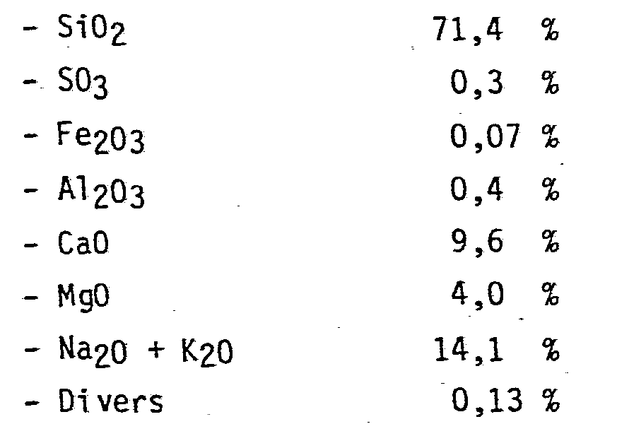
Les particules utilisées présentent des dimensions comprises entre 7 et 50 micromètres. L'essai a été conduit à 1600°C et avec un facteur d'air de 0,9.The particles used have dimensions between 7 and 50 micrometers. The test was conducted at 1600 ° C and with an air factor of 0.9.
Le rendement, bien que plus faible que précédemment, reste intéressant en pratique. Il se situe à environ 25 % en poids. La masse volumique des particules expansées est également élevée et voisine de 0,35 g/cm3.The yield, although lower than previously, remains interesting in practice. It is around 25% by weight. The density of the expanded particles is also high and around 0.35 g / cm3.
La mise en oeuvre de l'invention peut être effectuée en utilisant un dispositif tel que décrit dans ce qui suit, en faisant référence aux planches de dessins annexées dans lesquelles :
- - la figure 1 présente une vue schématique d'ensemble d'une installation de production des microsphères selon l'invention,
- - la figure 2 présente, en coupe, un modèle de dispositif de mise en suspension des particules avant leur injection dans le brûleur,
- - la figure 3 est une vue, en coupe, de la partie de l'installation dans laquelle l'expansion est effectuée,
- - la figure 4 est une vue partielle analogue à celle de la figure 3 montrant l'utilisation d'un autre type de brûleur.
- FIG. 1 presents a schematic overview of an installation for producing the microspheres according to the invention,
- FIG. 2 shows, in section, a model of a device for suspending the particles before their injection into the burner,
- FIG. 3 is a view, in section, of the part of the installation in which the expansion is carried out,
- - Figure 4 is a partial view similar to that of Figure 3 showing the use of another type of burner.
Contrairement à ce qui a été proposé dans la littérature, l'expansion des particules par les gaz de combustion est avantageusement effectuée en faisant circuler les particules de haut en bas dans le même sens que les gaz de combustion.Contrary to what has been proposed in the literature, the expansion of the particles by the combustion gases is advantageously carried out by circulating the particles from top to bottom in the same direction as the combustion gases.
Le choix des systèmes dans lesquels la circulation se fait de bas en haut résultait de l'idée suivante. Les particules expansées ayant une masse volumique moindre, un tri dynamique s'opère automatiquement entre ces particules expansées et celles qui ne le sont pas encore. Le maintien des particules non expansées dans les conditions de traitement était supposé permettre un accroissement du taux des particules finalement expansées.The choice of systems in which circulation is done from bottom to top resulted from the following idea. The expanded particles having a lower density, a dynamic sorting takes place automatically between these expanded particles and those which are not yet so. Maintaining the unexpanded particles under the treatment conditions was supposed to allow an increase in the rate of the finally expanded particles.
La pratique montre que cette façon de procéder ne permet pas d'obtenir une amélioration de rendement, bien au contraire. La circulation de bas en haut nécessite en effet des flux gazeux à vitesse relativement faible, les particules étant de petites dimensions "flottent" facilement dans les courants trop intenses. Par suite, les gaz étant animés d'une vitesse limitée, le temps de séjour des particules dans les conditions de traitement est relativement long.Practice shows that this way of proceeding does not make it possible to obtain a yield improvement, on the contrary. The circula tion from bottom to top requires gas flows at relatively low speed, the particles being small easily "float" in excessively strong currents. Consequently, the gases being driven at a limited speed, the residence time of the particles under the treatment conditions is relatively long.
Si cet allongement permet l'expansion de certaines particules qui, dans d'autres conditions, résisteraient au traitement, il a pour contrepartie le collapsus d'une part non négligeable des particules qui se sont préalablement expansées rapidement pour les raisons que nous avons déjà indiquées. Par ailleurs, les particules tendent à former des agrégats sur les parois. Globalement, ce mode de traitement de bas en haut n'est pas avantageux.If this elongation allows the expansion of certain particles which, under other conditions, would resist the treatment, it has as a counterpart the collapse of a non-negligible part of the particles which have previously rapidly expanded for the reasons which we have already indicated. . Furthermore, the particles tend to form aggregates on the walls. Overall, this bottom-up processing method is not advantageous.
En conséquence, selon l'invention, l'alimentation du dispositif dans lequel s'effectue l'expansion, un brûleur ou une enceinte en communication directe avec le brûleur, conduit les particules à circuler dans le même sens que le flux de gaz de combustion et de haut en bas.Consequently, according to the invention, the supply of the device in which the expansion takes place, a burner or an enclosure in direct communication with the burner, causes the particles to circulate in the same direction as the flow of combustion gases. and from top to bottom.
Dans la forme présentée à la figure 1, le dispositif de production des microsphères comprend les éléments suivants : un dispositif 1 pour la mise en suspension des particules dans un courant gazeux et leur transport jusqu'à la chambre de combustion d'un brûleur 2, le brûleur lui-même, une chambre 3 dans laquelle la combustion se poursuit, une enceinte de trempe 4. A cette partie de l'installation, dans laquelle s'effectue le traitement conduisant à l'expansion des microsphères, succède une série d'éléments dont le rôle est de séparer les sphères formées des gaz qui les entrainent d'une part et, d'autre part des poussières ou particules non expansées, ou encore d'agrégats de particules collées les unes aux autres. Sur la figure 1, l'ensemble des éléments de récupération des microsphères comprend un présélecteur 10, deux cyclones 5 et 6 et un filtre à manches 7.In the form shown in FIG. 1, the device for producing the microspheres comprises the following elements: a device 1 for suspending the particles in a gas stream and their transport to the combustion chamber of a
L'alimentation en particules devant s'opérer de façon régulière et continue dans un milieu réactionnel gazeux, un mode préféré consiste à entrainer les particules par un courant gazeux.Since the supply of particles has to take place in a regular and continuous manner in a gaseous reaction medium, a preferred mode consists in entraining the particles by a gas stream.
La mise en suspension dans un courant gazeux s'effectue de façon connue par exemple à partir d'un lit fluidisé de particules, par exemple au moyen du dispositif présenté à la figure 2.The suspension in a gas stream is carried out in a known manner for example from a fluidized bed of particles, for example by means of the device presented in FIG. 2.
Sur la figure 2, le lit fluidisé 11 est alimenté en particules par l'orifice 12 ménagé à sa partie supérieure. Par cet orifice 12 s'évacue également l'air insufflé sous le lit de particules et entrant par l'orifice 13.In FIG. 2, the
Une extrémité d'une conduite 14 est immergée dans le lit fluidisé 11. L'autre extrémité de cette conduite est reliée à une trompe venturi dans laquelle le gaz vecteur circule à vitesse élevée. La dépression engendrée dans le venturi 15 aspire les particules qui sont envoyées par la conduit 16 vers le brûleur.One end of a
Le débit et la vitesse des gaz transportant les particules sont choisis de manière à ce que les particules entrainées ne sédimentent pas au cours de leur trajet jusqu'à la chambre de réaction. Par ailleurs, lorsque de façon préférée l'alimentation se fait par le fond du brûleur, la vitesse et le débit du gaz véhiculant les particules doivent être maintenus dans des limites qui ne perturbent pas le bon fonctionnement du brûleur.The flow rate and speed of the gases transporting the particles are chosen so that the entrained particles do not sediment during their journey to the reaction chamber. Furthermore, when the supply is preferably made from the bottom of the burner, the speed and the flow rate of the gas carrying the particles must be kept within limits which do not disturb the proper functioning of the burner.
En pratique, le débit de gaz utilisé, le plus souvent de l'air, est très supérieur au débit de gaz nécessaire pour le simple transport pneumatique des particules. Cette quantité reste néanmoins habituellement très inférieure à celle qui est mise en jeu pour le fonctionnement du brûleur. Il convient cependant de tenir compte de cet apport d'air dans l'établissement des conditions d'alimentation du brûleur.In practice, the flow rate of gas used, most often air, is much greater than the flow rate of gas required for the simple pneumatic transport of the particles. This quantity nevertheless usually remains much less than that which is involved for the operation of the burner. However, this air supply must be taken into account when establishing the burner supply conditions.
Le gaz transportant les particules est de préférence de l'air ou un mélange air/gaz combustible alimentant ainsi au moins partiellement le brûleur dans lequel s'effectue l'expansion.The gas transporting the particles is preferably air or an air / fuel gas mixture thus at least partially supplying the burner in which the expansion takes place.
L'introduction de particules dans le brûleur est située de préférence de façon que, dans leur progression, les particules soient amenées à traverser le front. de flamme. Par ailleurs, l'introduction est faite de manière à éviter que les particules ne soient projetées sur les parois du brûleur notamment après qu'elles aient été portées à une température correspondant à leur ramollissement. De préférence, l'introduction des particules se fait suivant la direction correspondant à l'axe du brûleur.The introduction of particles into the burner is preferably located so that, in their progression, the particles are caused to cross the front. of flame. Furthermore, the introduction is made so as to prevent the particles from being projected onto the walls of the burner, in particular after they have been brought to a temperature corresponding to their softening. Preferably, the particles are introduced in the direction corresponding to the axis of the burner.
Le brûleur choisi pour l'expansion des particules doit d'abord permettre d'atteindre les températures requises qui se situent, comme nous l'avons vu, au-dessus de 1550°C. La quantité de chaleur dégagée par le brûleur doit aussi permettre de maintenir ces températures aux débits de particules envisagés.The burner chosen for the expansion of the particles must first make it possible to reach the required temperatures which are, as we have seen, above 1550 ° C. The amount of heat given off by the burner must also allow these temperatures to be maintained at the envisaged particle flow rates.
Les brûleurs internes dans lesquels la flamme est "accrochée" à une grille ou à des barreaux ne donnent pas de résultats satisfaisants. On constate, aux régimes envisagés, des résonances acoustiques qui sont très préjudiciables au bon fonctionnement du dispositif.Internal burners in which the flame is "hooked" to a grate or bars do not give satisfactory results. There are, at the regimes envisaged, acoustic resonances which are very detrimental to the proper functioning of the device.
Pour obtenir une bonne stabilité de flamme à haute température et sur une gamme de régimes de fonctionnement suffisamment étendue, il est avantageux, selon l'invention, d'utiliser un brûleur dans lequel la flamme se stabilise par exemple au contact des parois - tels que ceux du type décrit dans la demande de brevet français publiée sous le n° 2 524 610 - ou par une disposition particulière des admissions de gaz dans la chambre de combustion, comme par exemple dans les brûleurs décrits dans la publication de demande de brevet français n° 2 249 585.To obtain good flame stability at high temperature and over a sufficiently wide range of operating modes, it is advantageous, according to the invention, to use a burner in which the flame stabilizes for example in contact with the walls - such as those of the type described in the French patent application published under the number 2,524,610 - or by a particular arrangement of gas admissions into the combustion chamber, as for example in the burners described in the publication of French patent application n ° 2 249 585.
Il est possible, comme le montrent les deux publications antérieures citées, d'utiliser un prémélange ou un mélange direct dans la chambre de combustion.It is possible, as the two cited previous publications show, to use a premix or a direct mixture in the combustion chamber.
Pour accroitre la température de fonctionnement, il est aussi possible de procéder à un préchauffage des gaz admis dans la chambre de combustion du brûleur.To increase the operating temperature, it is also possible to preheat the gases admitted to the combustion chamber of the burner.
Il est possible, également, d'utiliser un mélange gazeux plus énergétique par exemple un mélange enrichi en oxygène. Cette dernière solution n'est pas souhaitable, en règle générale, dans la mesure où elle entraine un accroissement des coûts de production.It is also possible to use a more energetic gas mixture, for example an oxygen-enriched mixture. The latter solution is generally undesirable since it leads to an increase in production costs.
De préférence encore, le brûleur utilisé doit pouvoir ménager des zones dans lesquelles le mélange gazeux est réducteur. Une telle disposition est obtenue en particulier lorsque l'air nécessaire à la combustion (ou le nélange oxydant utilisé) est introduit à au noms deux niveaux sur le chemin de progression des gaz dans la chambre de combustion, l'un au moins de ces niveaux étant situé en aval de l'introduction du gaz combustible. Dans ces conditions, la combustion qui prend naissance en premier est nécessairement réductrice par défaut d'oxygène.More preferably, the burner used must be able to provide areas in which the gas mixture is reducing. Such an arrangement is obtained in particular when the air necessary for combustion (or the oxidizing mixture used) is introduced at names two levels on the path of progression of the gases in the combustion chamber, at least one of these levels being located downstream of the introduction of the combustible gas. Under these conditions, the combustion which starts first is necessarily reducing by lack of oxygen.
La longueur de la chambre de combustion 2 et de la chambre 3 est fonction du temps de séjour nécessaire pour le traitement efficace des particules. Bien que la vitesse de circulation soit grande (de l'ordre de 25 m/s), le traitement étant très rapide, la longueur de cette partie où s'effectue le traitement thermique est relativement limitée.The length of the
A titre indicatif, la longueur totale de la zone de combustion est avantageusement comprise entre 6 et 50 cm, et de préférence entre 10 et 25 cm.As an indication, the total length of the combustion zone is advantageously between 6 and 50 cm, and preferably between 10 and 25 cm.
Cette partie du dispositif, dans laquelle règne la température la plus élevée, est limitée en aval par la zone dans laquelle s'effectue l'introduction massive d'air à température ambiante pour assurer la "trempe" des microsphères formées.This part of the device, in which the highest temperature prevails, is limited downstream by the zone in which eff performs the massive introduction of air at room temperature to ensure the "quenching" of the microspheres formed.
La brieveté du séjour dans la zone de traitement thermique évite, comme nous l'avons vu, les risques de collapsus et d'agrégation des particules ou de collage sur les parois. Pour diminuer encore les risques de collage sur les parois de la chambre 3, celles-ci sont avantageusement soumises à un refroidissement intense maintenant leur température à une valeur inférieure à celle à laquelle le verre reste ramolli et donc collant.The brevity of the stay in the heat treatment zone avoids, as we have seen, the risks of collapse and aggregation of particles or of sticking to the walls. To further reduce the risk of sticking to the walls of the
Le refroidissement des parois de la chambre 3 est obtenu, par exemple, au moyen d'une chemise dans laquelle est aménagée une circulation d'eau ou d'air.The cooling of the walls of
Vis-à-vis des techniques antérieures, la chambre de combustion utilisée selon l'invention présente plusieurs caractéristiques avantageuses pour la mise en oeuvre de ces procédés. Ainsi, de préférence, la totalité de la section de la chambre est en pratique le siège de la combustion. Autrement dit, la flamme occupant toute la section, les particules qui passent dans la chambre doivent nécessairement passer dans la flamme et donc franchir les différentes étapes oxydo-réductrices aménagées.With respect to the prior techniques, the combustion chamber used according to the invention has several advantageous characteristics for the implementation of these methods. Thus, preferably, the entire section of the chamber is in practice the seat of combustion. In other words, the flame occupying the entire section, the particles which pass into the chamber must necessarily pass through the flame and therefore pass through the various oxidative-reducing stages arranged.
La section de la chambre de combustion est, en outre, sensiblement constante sur toute la longueur correspondant à la zone d'expansion des particules, c'est-à-dire dans la partie qui précède l'introduction de l'air de trempe.The section of the combustion chamber is, moreover, substantially constant over the entire length corresponding to the zone of expansion of the particles, that is to say in the part which precedes the introduction of the quenching air.
Le confinement de la réaction dans une chambre de combustion de section relativement restreinte garantit le maintien d'une température élevée et un temps de séjour très bref, conditions qui sont particulièrement recherchées selon l'invention.The confinement of the reaction in a combustion chamber of relatively small section guarantees the maintenance of a high temperature and a very short residence time, conditions which are particularly sought after according to the invention.
Un exemple de chambre de combustion utilisé selon l'invention est représenté à la figure 3.An example of a combustion chamber used according to the invention is shown in FIG. 3.
Les particules et le gaz qui les transporte est introduit par la conduite 17 dans l'axe du dispositif.The particles and the gas which transports them is introduced via
Le brûleur, de forme cylindrique, comporte une alimentation en gaz 18. De la chambre annulaire 19, le gaz est envoyé par les orifices 20 dans la zone de combustion.The burner, of cylindrical shape, includes a
L'air est amené par la conduite 21 dans une chambre annulaire 22 et passe dans la zone de combustion par deux séries d'orifices 23 et 24. Ces derniers sont orientés de façon à communiquer à l'air introduit des mouvements de rotation de sens inverses.The air is brought through the
Dans le mode représenté à la figure 4, le brûleur du type décrit dans la demande de brevet français n° 2 524 610 est constitué par une chambre à parois réfractaires 28. Comme pour le mode représenté à la figure 3, l'admission des particules s'effectue au sommet de la chambre par la canalisation 17.In the mode represented in FIG. 4, the burner of the type described in French patent application No. 2 524 610 consists of a chamber with
Une double enveloppe 29 entoure la chambre de combustion. Dans cette enveloppe circule le mélange combustible amené par la conduite 30.A
Au cours de son passage dans la double enveloppe le long des parois externes de la chambre, le mélange se réchauffe. Il est introduit dans la chambre par des orifices 31 creusés dans la base réfractaire.During its passage through the double jacket along the external walls of the chamber, the mixture heats up. It is introduced into the chamber through
La position des orifices 31 est choisie de façon que l'admission du mélange se fasse à contre-courant de la circulation des gaz de combustion et le long des parois réfractaires. Cette disposition est particulièrement avantageuse pour atteindre des températures élevées et une grande stabilité de fonctionnement.The position of the
Les deux brûleurs précédents peuvent être utilisés avec un appareillage qui pour le restant peut être identique. La figure 3 illustre la partie de cet appareillage faisant immédiatement suite au brûleur.The two previous burners can be used with an appliance which for the rest can be identical. Figure 3 illustrates the part of this equipment immediately following the burner.
La chambre de combustion est prolongée par un élément 25 comprenant une paroi réfractaire enveloppée dans une chemise métallique. Toujours dans le prolongement, la chambre de combustion 3 est ensuite délimitée par une double paroi métallique 27 dans laquelle circule de l'eau de refroidissement.The combustion chamber is extended by an
On constate, en maintenant la température de cette paroi à une valeur inférieure à celle à laquelle les particules de verre en fusion peuvent adhérer, que non seulement on évite la formation de dépôts ou d'agrégats sur les parois, mais encore que la présence de cette paroi refroidie ne constitue pas une gêne sensible à l'obtention des conditions de températures élevées nécessaires.It is found, by maintaining the temperature of this wall at a value lower than that to which the particles of molten glass can adhere, that not only is it avoided the formation of deposits or aggregates on the walls, but also that the presence of this cooled wall does not constitute a significant discomfort in obtaining the necessary high temperature conditions.
Compte tenu des verres ordinairement utilisés, la température de la paroi est avantageusement maintenue inférieure à 150°C.Taking into account the glasses ordinarily used, the temperature of the wall is advantageously kept below 150 ° C.
La trempe est réalisée dans une enceinte de volume relativement grand par rapport à celui de la chambre de combustion.The quenching is carried out in an enclosure of relatively large volume compared to that of the combustion chamber.
L'air de trempe est admis à la partie supérieure de cette enceinte par les ouvertures 9. Dans cette partie supérieure débouchent également les gaz et les particules provenant de la chambre 3.The quenching air is admitted to the upper part of this enclosure through the
L'admission de l'air dans la chambre de trempe est réglée par l'aspiration entretenue à l'extrémité des éléments du dispositif servant à la séparation gaz/solides.The admission of air into the quenching chamber is regulated by the suction maintained at the end of the elements of the device used for the gas / solid separation.
L'abaissement de la température des gaz circulant, consécutif à l'introduction d'air ambiant est complété pendant le cheminement dans l'enceinte de trempe par les échanges thermiques qui s'opèrent par les parois de cette enceinte au contact de l'air ambiant.The lowering of the temperature of the circulating gases, following the introduction of ambient air is completed during the passage in the quenching chamber by the heat exchanges which take place through the walls of this chamber in contact with the air. ambient.
Dans l'enceinte de trempe, la section est également suffisante pour réduire la vitesse de circulation des gaz. Cette réduction de vitesse permet, au pied de l'enceinte, d'effectuer un premier tri dynamique. Les particules les plus grosses formées essentiellement par des agrégats se déposent dans le préselecteur 10.In the quenching chamber, the section is also sufficient to reduce the speed of circulation of the gases. This speed reduction allows, at the foot of the enclosure, to make a first dynamic sorting. The largest particles formed essentially by aggregates are deposited in the
Dans les conditions de travail indiquées précédemment, la fraction de produit initial formant des agrégats ne dépasse normalement pas 1 à 2 % en poids du produit initial.Under the working conditions indicated above, the fraction of initial product forming aggregates normally does not exceed 1 to 2% by weight of the initial product.
Les différentes sections dans le présélecteur et les conditions d'aspiration sont aussi réglées de façon que les particules expansées soient entrainées hors du présélecteur par les gaz et se déposent dans le ou les moyens utilisés pour séparer les particules des gaz qui les véhiculent.The different sections in the preselector and the suction conditions are also adjusted so that the expanded particles are entrained out of the preselector by the gases and are deposited in the means or means used to separate the particles from the gases which carry them.
Sur la figure 1, ces moyens sont constitués par deux cyclones 5 et 6 et par un dispositif de filtre à manches 7 dont la sortie est en communication avec un ventilateur d'aspiration non représenté.In FIG. 1, these means consist of two
La récupération des microsphères se fait au bas des cyclones et des filtres à manches.The microspheres are recovered at the bottom of the cyclones and the bag filters.
En fonction des caractéristiques des moyens de séparation et de la vitesse de circulation des gaz, il est possible de réaliser un tri des particules. Ainsi, normalement, les particules les plus fines se retrouvent séparées au niveau du filtre à manches.Depending on the characteristics of the separation means and the gas circulation speed, it is possible to sort the particles. Normally, the finest particles are separated at the bag filter.
Claims (22)
Priority Applications (1)
| Application Number | Priority Date | Filing Date | Title |
|---|---|---|---|
| AT85401232T ATE34162T1 (en) | 1984-06-21 | 1985-06-20 | PROCESS FOR MAKING GLASS MICROBALLS. |
Applications Claiming Priority (2)
| Application Number | Priority Date | Filing Date | Title |
|---|---|---|---|
| FR8409736 | 1984-06-21 | ||
| FR8409736A FR2566384B1 (en) | 1984-06-21 | 1984-06-21 | IMPROVEMENTS IN TECHNIQUES FOR THE PRODUCTION OF GLASS MICROSPHERES |
Publications (2)
| Publication Number | Publication Date |
|---|---|
| EP0165875A1 true EP0165875A1 (en) | 1985-12-27 |
| EP0165875B1 EP0165875B1 (en) | 1988-05-11 |
Family
ID=9305271
Family Applications (1)
| Application Number | Title | Priority Date | Filing Date |
|---|---|---|---|
| EP85401232A Expired EP0165875B1 (en) | 1984-06-21 | 1985-06-20 | Method of making microspheres from glass |
Country Status (7)
| Country | Link |
|---|---|
| US (1) | US4661137A (en) |
| EP (1) | EP0165875B1 (en) |
| JP (1) | JPH0623061B2 (en) |
| AT (1) | ATE34162T1 (en) |
| CA (1) | CA1282963C (en) |
| DE (1) | DE3562611D1 (en) |
| FR (1) | FR2566384B1 (en) |
Cited By (5)
| Publication number | Priority date | Publication date | Assignee | Title |
|---|---|---|---|---|
| EP0236228A1 (en) * | 1986-03-03 | 1987-09-09 | Saint Gobain Vitrage International | Production of microspheres in glass |
| US4767726A (en) * | 1987-01-12 | 1988-08-30 | Minnesota Mining And Manufacturing Company | Glass microbubbles |
| EP0302785A1 (en) * | 1987-08-05 | 1989-02-08 | Saint-Gobain Vitrage International | Method for producing silica microspheres |
| FR2671072A1 (en) * | 1990-11-14 | 1992-07-03 | Saint Gobain Vitrage Int | Silica-soda-lime glass, microspheres obtained from this glass and process for their manufacture |
| RU2491238C2 (en) * | 2011-08-24 | 2013-08-27 | Закрытое акционерное общество "Стромизмеритель" | Mixture for making quenched cullet for foamed glass |
Families Citing this family (82)
| Publication number | Priority date | Publication date | Assignee | Title |
|---|---|---|---|---|
| US4983550A (en) * | 1988-08-24 | 1991-01-08 | Potters Industries, Inc. | Hollow glass spheres |
| US5217928A (en) * | 1988-08-24 | 1993-06-08 | Potters Industries, Inc. | Hollow glass spheres |
| DE3990975T1 (en) * | 1988-08-24 | 1991-08-29 | Potters Industries Inc | HOLLOW GLASS BALLS |
| US5069702A (en) * | 1990-12-20 | 1991-12-03 | W. R. Grace & Co.-Conn. | Method of making small hollow glass spheres |
| US5292690A (en) * | 1991-03-29 | 1994-03-08 | Nippon Electric Glass Company, Ltd. | Glass composition for glass bubbles with increased compressive strength |
| US5611833A (en) * | 1992-08-26 | 1997-03-18 | Mg Industries | Method and apparatus for producing spheroidal glass particles |
| KR970702827A (en) * | 1994-04-25 | 1997-06-10 | 워렌 리차드 보비 | COMPOSITIONS COMPRISING FUSED PARTICULATES AND METHODS OF MAKING THEM |
| US6045913A (en) * | 1995-11-01 | 2000-04-04 | Minnesota Mining And Manufacturing Company | At least partly fused particulates and methods of making them by flame fusion |
| US6254981B1 (en) | 1995-11-02 | 2001-07-03 | Minnesota Mining & Manufacturing Company | Fused glassy particulates obtained by flame fusion |
| JP3633091B2 (en) * | 1996-04-09 | 2005-03-30 | 旭硝子株式会社 | Method for producing minute inorganic spherical solid body |
| US6098810A (en) * | 1998-06-26 | 2000-08-08 | Pueblo Process, Llc | Flotation process for separating silica from feldspar to form a feed material for making glass |
| KR100853920B1 (en) | 2000-03-14 | 2008-08-25 | 제임스 하디 인터내셔널 파이낸스 비.브이. | Fiber cement building materials with low density additives |
| KR100436203B1 (en) * | 2001-09-24 | 2004-06-16 | 김병일 | foam glass and method for manufacture of it |
| US7094369B2 (en) * | 2002-03-29 | 2006-08-22 | Scimed Life Systems, Inc. | Processes for manufacturing polymeric microspheres |
| US7462366B2 (en) * | 2002-03-29 | 2008-12-09 | Boston Scientific Scimed, Inc. | Drug delivery particle |
| US7131997B2 (en) * | 2002-03-29 | 2006-11-07 | Scimed Life Systems, Inc. | Tissue treatment |
| US7053134B2 (en) | 2002-04-04 | 2006-05-30 | Scimed Life Systems, Inc. | Forming a chemically cross-linked particle of a desired shape and diameter |
| CA2492339A1 (en) * | 2002-06-12 | 2003-12-24 | Boston Scientific Limited | Bulking agents |
| US7842377B2 (en) * | 2003-08-08 | 2010-11-30 | Boston Scientific Scimed, Inc. | Porous polymeric particle comprising polyvinyl alcohol and having interior to surface porosity-gradient |
| US7449236B2 (en) * | 2002-08-09 | 2008-11-11 | Boston Scientific Scimed, Inc. | Porous polymeric particle comprising polyvinyl alcohol and having interior to surface porosity-gradient |
| US7455798B2 (en) * | 2002-08-23 | 2008-11-25 | James Hardie International Finance B.V. | Methods for producing low density products |
| AU2003250614B2 (en) * | 2002-08-23 | 2010-07-15 | James Hardie Technology Limited | Synthetic hollow microspheres |
| US8012454B2 (en) | 2002-08-30 | 2011-09-06 | Boston Scientific Scimed, Inc. | Embolization |
| MXPA05003691A (en) | 2002-10-07 | 2005-11-17 | James Hardie Int Finance Bv | Durable medium-density fibre cement composite. |
| US7588825B2 (en) * | 2002-10-23 | 2009-09-15 | Boston Scientific Scimed, Inc. | Embolic compositions |
| US7883490B2 (en) * | 2002-10-23 | 2011-02-08 | Boston Scientific Scimed, Inc. | Mixing and delivery of therapeutic compositions |
| US20220127182A1 (en) * | 2017-03-23 | 2022-04-28 | Edgar Edward Jaunzemis | Tumbled, polished, vibrated broken tempered glass pieces |
| US20090146108A1 (en) * | 2003-08-25 | 2009-06-11 | Amlan Datta | Methods and Formulations for Producing Low Density Products |
| US7976823B2 (en) * | 2003-08-29 | 2011-07-12 | Boston Scientific Scimed, Inc. | Ferromagnetic particles and methods |
| US20090156385A1 (en) * | 2003-10-29 | 2009-06-18 | Giang Biscan | Manufacture and use of engineered carbide and nitride composites |
| US7901770B2 (en) * | 2003-11-04 | 2011-03-08 | Boston Scientific Scimed, Inc. | Embolic compositions |
| US7298078B2 (en) * | 2004-01-14 | 2007-11-20 | E-Lite Technologies, Inc. | Flat, flexible fluorescent lamp |
| US7736671B2 (en) * | 2004-03-02 | 2010-06-15 | Boston Scientific Scimed, Inc. | Embolization |
| US8173176B2 (en) | 2004-03-30 | 2012-05-08 | Boston Scientific Scimed, Inc. | Embolization |
| US20050238870A1 (en) * | 2004-04-22 | 2005-10-27 | Marcia Buiser | Embolization |
| US7311861B2 (en) * | 2004-06-01 | 2007-12-25 | Boston Scientific Scimed, Inc. | Embolization |
| US7998571B2 (en) | 2004-07-09 | 2011-08-16 | James Hardie Technology Limited | Composite cement article incorporating a powder coating and methods of making same |
| US20060026900A1 (en) * | 2004-08-09 | 2006-02-09 | Jang Bor Z | Method for storing and delivering hydrogen to fuel cells |
| US20060063003A1 (en) * | 2004-09-20 | 2006-03-23 | Laixia Yang | Infrared-absorbing glass micro-spheres for storing and delivering hydrogen to fuel cells |
| US20060060820A1 (en) * | 2004-09-21 | 2006-03-23 | Schumacher Ray F | Hollow porous-wall glass microspheres for hydrogen storage |
| US7666807B2 (en) * | 2004-09-21 | 2010-02-23 | Savannah River Nuclear Solutions, Llc | Hollow porous-wall glass microspheres for hydrogen storage |
| US8425550B2 (en) * | 2004-12-01 | 2013-04-23 | Boston Scientific Scimed, Inc. | Embolic coils |
| US20060122049A1 (en) * | 2004-12-03 | 2006-06-08 | 3M Innovative Properties Company | Method of making glass microbubbles and raw product |
| AU2006216407A1 (en) * | 2005-02-24 | 2006-08-31 | James Hardie Technology Limited | Alkali resistant glass compositions |
| US7727555B2 (en) * | 2005-03-02 | 2010-06-01 | Boston Scientific Scimed, Inc. | Particles |
| US7858183B2 (en) * | 2005-03-02 | 2010-12-28 | Boston Scientific Scimed, Inc. | Particles |
| US7963287B2 (en) | 2005-04-28 | 2011-06-21 | Boston Scientific Scimed, Inc. | Tissue-treatment methods |
| US20070004973A1 (en) * | 2005-06-15 | 2007-01-04 | Tan Sharon M L | Tissue treatment methods |
| US9463426B2 (en) * | 2005-06-24 | 2016-10-11 | Boston Scientific Scimed, Inc. | Methods and systems for coating particles |
| US20070083219A1 (en) * | 2005-10-12 | 2007-04-12 | Buiser Marcia S | Embolic coil introducer sheath locking mechanisms |
| US8007509B2 (en) * | 2005-10-12 | 2011-08-30 | Boston Scientific Scimed, Inc. | Coil assemblies, components and methods |
| WO2007067774A2 (en) * | 2005-12-08 | 2007-06-14 | James Hardie International Finance B.V. | Engineered low-density heterogeneous microparticles and methods and formulations for producing the microparticles |
| US8152839B2 (en) * | 2005-12-19 | 2012-04-10 | Boston Scientific Scimed, Inc. | Embolic coils |
| US8101197B2 (en) | 2005-12-19 | 2012-01-24 | Stryker Corporation | Forming coils |
| US20070142859A1 (en) * | 2005-12-19 | 2007-06-21 | Boston Scientific Scimed, Inc. | Embolic coils |
| US7947368B2 (en) * | 2005-12-21 | 2011-05-24 | Boston Scientific Scimed, Inc. | Block copolymer particles |
| US7501179B2 (en) * | 2005-12-21 | 2009-03-10 | Boston Scientific Scimed, Inc. | Block copolymer particles |
| US20070142560A1 (en) * | 2005-12-21 | 2007-06-21 | Young-Ho Song | Block copolymer particles |
| JP5411497B2 (en) * | 2006-03-08 | 2014-02-12 | 電気化学工業株式会社 | Inorganic hollow powder, method for producing the same, and composition containing the inorganic hollow powder |
| CA2648966C (en) | 2006-04-12 | 2015-01-06 | James Hardie International Finance B.V. | A surface sealed reinforced building element |
| US20070275335A1 (en) * | 2006-05-25 | 2007-11-29 | Giang Biscan | Furnace for heating particles |
| US20070299461A1 (en) * | 2006-06-21 | 2007-12-27 | Boston Scientific Scimed, Inc. | Embolic coils and related components, systems, and methods |
| US8414927B2 (en) * | 2006-11-03 | 2013-04-09 | Boston Scientific Scimed, Inc. | Cross-linked polymer particles |
| WO2008069777A1 (en) * | 2006-12-04 | 2008-06-12 | Savannah River Nuclear Solutions, Llc | Apparatus and process to enhance the uniform formation of hollow glass microspheres |
| US20080145658A1 (en) * | 2006-12-15 | 2008-06-19 | Boston Scientific Scimed, Inc. | Freeze Thaw Methods For Making Polymer Particles |
| US8209927B2 (en) | 2007-12-20 | 2012-07-03 | James Hardie Technology Limited | Structural fiber cement building materials |
| US7900474B2 (en) * | 2008-08-14 | 2011-03-08 | Beck Warren R | Hollow glass microspheres comprising selenium oxide and method of making thereof |
| US20100139320A1 (en) * | 2008-12-04 | 2010-06-10 | Savannah River Nulcear Solutions, Llc | Hollow porous-wall glass microspheres and composition and process for controlling pore size and pore volume |
| US20110152057A1 (en) * | 2009-12-21 | 2011-06-23 | Gang Qi | Hollow microspheres |
| US8261577B2 (en) * | 2009-12-21 | 2012-09-11 | 3M Innovative Properties Company | Method for making hollow microspheres |
| WO2012033810A1 (en) | 2010-09-08 | 2012-03-15 | 3M Innovative Properties Company | Glass bubbles, composites therefrom, and method of making glass bubbles |
| EA028106B1 (en) * | 2010-12-20 | 2017-10-31 | 3М Инновейтив Пропертиз Компани | Hollow microspheres and method of making hollow microspheres |
| US11225430B2 (en) | 2012-03-26 | 2022-01-18 | Steven Jung | Bioactive glass scaffolds, and method of making |
| US9045362B2 (en) | 2013-03-15 | 2015-06-02 | Mosci Corp. | Bioactive glass scaffolds, and method of making |
| CN103588391B (en) * | 2012-08-15 | 2015-12-09 | 中国石油化工股份有限公司 | A kind of hollow glass micropearl and preparation method thereof |
| WO2014120172A1 (en) | 2013-01-31 | 2014-08-07 | Empire Technology Development Llc | Light weight structural materials |
| AU2013221955B2 (en) * | 2013-04-12 | 2017-06-22 | Mosci Corp. | Bioactive glass scaffolds, and method of making |
| US9016090B2 (en) * | 2013-06-12 | 2015-04-28 | Hamid Hojaji | Glass microspheres comprising sulfide, and methods of producing glass microspheres |
| EP3099639B1 (en) * | 2014-01-27 | 2017-12-20 | Ingenieurbüro Franke GlasTechnologie-Service | Method and device for producing hollow glass spheres |
| US10196296B2 (en) | 2015-01-17 | 2019-02-05 | Hamid Hojaji | Fluid permeable and vacuumed insulating microspheres and methods of producing the same |
| US9643876B2 (en) | 2015-10-04 | 2017-05-09 | Hamid Hojaji | Microspheres and methods of making the same |
| RU2749764C1 (en) * | 2020-11-23 | 2021-06-16 | Автономная некоммерческая организация высшего образования «Белгородский университет кооперации, экономики и права», | Method for producing composite micro-balls |
Citations (2)
| Publication number | Priority date | Publication date | Assignee | Title |
|---|---|---|---|---|
| US3838998A (en) * | 1971-01-07 | 1974-10-01 | R Carson | Process for forming hollow glass micro-spheres from admixed high and low temperature glass formers |
| FR2318123A1 (en) * | 1975-07-17 | 1977-02-11 | Sovitec Sa | EXPANDABLE BEADS MANUFACTURING PROCESS |
Family Cites Families (10)
| Publication number | Priority date | Publication date | Assignee | Title |
|---|---|---|---|---|
| US2911669A (en) * | 1955-03-30 | 1959-11-10 | Parker Pen Co | Method and apparatus for forming spheres |
| GB960902A (en) * | 1960-05-25 | 1964-06-17 | Dennert Heinz | Apparatus for manufacturing a porous material, more particularly blown clay, by heating |
| US3365315A (en) * | 1963-08-23 | 1968-01-23 | Minnesota Mining & Mfg | Glass bubbles prepared by reheating solid glass partiles |
| JPS4894713A (en) * | 1972-03-21 | 1973-12-06 | ||
| FR2249585A5 (en) * | 1973-10-26 | 1975-05-23 | Gaz De France | High-temp. gas burner for cupolas - uses low-press. gas and permits partial replacement of coke by gas |
| US4017290A (en) * | 1974-04-15 | 1977-04-12 | Kms Fusion, Inc. | Method and apparatus for making uniform pellets for fusion reactors |
| JPS5932413B2 (en) * | 1981-10-27 | 1984-08-08 | 宇部興産株式会社 | Foamed mineral grain firing equipment |
| EP0086599A1 (en) * | 1982-02-12 | 1983-08-24 | Redland Technologies Limited | Method and apparatus for the heat processing of particulate materials |
| US4391646A (en) * | 1982-02-25 | 1983-07-05 | Minnesota Mining And Manufacturing Company | Glass bubbles of increased collapse strength |
| FR2524610B1 (en) * | 1982-04-06 | 1987-02-06 | Saint Gobain Isover | IMPROVEMENTS ON INTERNAL COMBUSTION BURNERS |
-
1984
- 1984-06-21 FR FR8409736A patent/FR2566384B1/en not_active Expired
-
1985
- 1985-06-14 CA CA000484072A patent/CA1282963C/en not_active Expired - Fee Related
- 1985-06-20 DE DE8585401232T patent/DE3562611D1/en not_active Expired
- 1985-06-20 EP EP85401232A patent/EP0165875B1/en not_active Expired
- 1985-06-20 US US06/747,141 patent/US4661137A/en not_active Expired - Lifetime
- 1985-06-20 AT AT85401232T patent/ATE34162T1/en not_active IP Right Cessation
- 1985-06-21 JP JP60134395A patent/JPH0623061B2/en not_active Expired - Fee Related
Patent Citations (2)
| Publication number | Priority date | Publication date | Assignee | Title |
|---|---|---|---|---|
| US3838998A (en) * | 1971-01-07 | 1974-10-01 | R Carson | Process for forming hollow glass micro-spheres from admixed high and low temperature glass formers |
| FR2318123A1 (en) * | 1975-07-17 | 1977-02-11 | Sovitec Sa | EXPANDABLE BEADS MANUFACTURING PROCESS |
Cited By (7)
| Publication number | Priority date | Publication date | Assignee | Title |
|---|---|---|---|---|
| EP0236228A1 (en) * | 1986-03-03 | 1987-09-09 | Saint Gobain Vitrage International | Production of microspheres in glass |
| US4767726A (en) * | 1987-01-12 | 1988-08-30 | Minnesota Mining And Manufacturing Company | Glass microbubbles |
| AU589819B2 (en) * | 1987-01-12 | 1989-10-19 | Minnesota Mining And Manufacturing Company | Glass microbubbles |
| EP0302785A1 (en) * | 1987-08-05 | 1989-02-08 | Saint-Gobain Vitrage International | Method for producing silica microspheres |
| FR2619101A1 (en) * | 1987-08-05 | 1989-02-10 | Saint Gobain Vitrage | TECHNIQUE FOR THE PRODUCTION OF MICROSPHERES IN SILICA |
| FR2671072A1 (en) * | 1990-11-14 | 1992-07-03 | Saint Gobain Vitrage Int | Silica-soda-lime glass, microspheres obtained from this glass and process for their manufacture |
| RU2491238C2 (en) * | 2011-08-24 | 2013-08-27 | Закрытое акционерное общество "Стромизмеритель" | Mixture for making quenched cullet for foamed glass |
Also Published As
| Publication number | Publication date |
|---|---|
| JPH0623061B2 (en) | 1994-03-30 |
| ATE34162T1 (en) | 1988-05-15 |
| DE3562611D1 (en) | 1988-06-16 |
| FR2566384B1 (en) | 1986-09-05 |
| CA1282963C (en) | 1991-04-16 |
| JPS6114147A (en) | 1986-01-22 |
| FR2566384A1 (en) | 1985-12-27 |
| US4661137A (en) | 1987-04-28 |
| EP0165875B1 (en) | 1988-05-11 |
Similar Documents
| Publication | Publication Date | Title |
|---|---|---|
| EP0165875B1 (en) | Method of making microspheres from glass | |
| CA2468177C (en) | Device and method for melting vitrifiable materials | |
| EP0970021B1 (en) | Method and device for melting and refining materials capable of being vitrified | |
| CA2283252C (en) | Method and device for melting and refining materials capable of being vitrified | |
| EP0048713B1 (en) | Process for manufacturing metal pellets, product obtained thereby and device for implementing such process | |
| FR2886934A1 (en) | QUARTZ GLASS INGOTS WITH FREE FORMATION AND METHOD OF MANUFACTURING THE SAME | |
| EP1904408B1 (en) | Method for glass preparation | |
| FR2880013A1 (en) | Purification of natural/synthetic silica powder, useful in production of synthetic quartz glass powder, comprises treating silica powder in oxidizing atmosphere to reduce content of silica powder in carbonated compound | |
| FR2468549A1 (en) | PROCESS FOR MANUFACTURING SPHERICAL PARTICLES OF WELL-UNIFORM DIMENSIONS, OF CARBON AND, PARTICULARLY, OF ACTIVE CARBON | |
| FR2528031A1 (en) | METHOD AND DEVICE FOR THE MANUFACTURE OF ROUND VARIOUS PEARLS | |
| FR2913971A1 (en) | GLASS FUSION DEVICE COMPRISING TWO OVENS | |
| EP1599423A1 (en) | Method for the production of glass from a mixture of various metals | |
| BE497377A (en) | IMPROVEMENTS IN METHODS AND APPARATUS FOR THE PRODUCTION OF CARBON BLACK | |
| FR2663564A1 (en) | PROCESS FOR OBTAINING HIGHLY PERMEABLE CALCIN DIATOMIC FILTERING AGENTS FREE OF CRISTOBALITY, AND HIGHLY PERMEABLE CALCINATED DIATOMIC FILTERING AGENTS FREE OF CRISTOBALITY. | |
| BE1005902A3 (en) | Spherulization FURNACE AND METHOD OF MAKING BEADS IN VITREOUS. | |
| WO1987005595A1 (en) | Method for lubricating a surface such as a mould for the fabrication of a glass object | |
| FR3083539A1 (en) | PREPARATION OF RAW MATERIALS FOR GLASS OVEN | |
| EP0246157A1 (en) | Processes and apparatuses for melting fibrous materials | |
| WO2015166172A1 (en) | Method and device for melting and refining glass | |
| EP0135446B1 (en) | Method and apparatus for melting glass and uses of this apparatus | |
| CA2423140C (en) | Method for preparing nuclear metal or metal alloy particles | |
| FR2585348A1 (en) | METHOD AND DEVICE FOR THE MANUFACTURE OF GLASS PEARLS | |
| FR2645542A1 (en) | METHOD FOR CONTROLLING THE SIZE OF THE AGGREGATES AND THE STRUCTURE OF CARBON BLACKS | |
| CA2404500C (en) | Method and device for thermal treatment of steel wire | |
| EP0236228B1 (en) | Production of microspheres in glass |
Legal Events
| Date | Code | Title | Description |
|---|---|---|---|
| PUAI | Public reference made under article 153(3) epc to a published international application that has entered the european phase |
Free format text: ORIGINAL CODE: 0009012 |
|
| AK | Designated contracting states |
Designated state(s): AT BE CH DE FR GB IT LI LU NL SE |
|
| 17P | Request for examination filed |
Effective date: 19860208 |
|
| 17Q | First examination report despatched |
Effective date: 19861118 |
|
| D17Q | First examination report despatched (deleted) | ||
| GRAA | (expected) grant |
Free format text: ORIGINAL CODE: 0009210 |
|
| AK | Designated contracting states |
Kind code of ref document: B1 Designated state(s): AT BE CH DE FR GB IT LI LU NL SE |
|
| REF | Corresponds to: |
Ref document number: 34162 Country of ref document: AT Date of ref document: 19880515 Kind code of ref document: T |
|
| REF | Corresponds to: |
Ref document number: 3562611 Country of ref document: DE Date of ref document: 19880616 |
|
| ITF | It: translation for a ep patent filed |
Owner name: DR. ING. A. RACHELI & C. |
|
| GBT | Gb: translation of ep patent filed (gb section 77(6)(a)/1977) | ||
| PLBE | No opposition filed within time limit |
Free format text: ORIGINAL CODE: 0009261 |
|
| STAA | Information on the status of an ep patent application or granted ep patent |
Free format text: STATUS: NO OPPOSITION FILED WITHIN TIME LIMIT |
|
| 26N | No opposition filed | ||
| PGFP | Annual fee paid to national office [announced via postgrant information from national office to epo] |
Ref country code: LU Payment date: 19910329 Year of fee payment: 7 |
|
| PGFP | Annual fee paid to national office [announced via postgrant information from national office to epo] |
Ref country code: AT Payment date: 19910410 Year of fee payment: 7 |
|
| PGFP | Annual fee paid to national office [announced via postgrant information from national office to epo] |
Ref country code: SE Payment date: 19910503 Year of fee payment: 7 |
|
| PGFP | Annual fee paid to national office [announced via postgrant information from national office to epo] |
Ref country code: GB Payment date: 19910515 Year of fee payment: 7 |
|
| ITTA | It: last paid annual fee | ||
| PGFP | Annual fee paid to national office [announced via postgrant information from national office to epo] |
Ref country code: NL Payment date: 19910630 Year of fee payment: 7 |
|
| PGFP | Annual fee paid to national office [announced via postgrant information from national office to epo] |
Ref country code: CH Payment date: 19910701 Year of fee payment: 7 |
|
| EPTA | Lu: last paid annual fee | ||
| PG25 | Lapsed in a contracting state [announced via postgrant information from national office to epo] |
Ref country code: LU Free format text: LAPSE BECAUSE OF NON-PAYMENT OF DUE FEES Effective date: 19920620 Ref country code: GB Effective date: 19920620 Ref country code: AT Effective date: 19920620 |
|
| PG25 | Lapsed in a contracting state [announced via postgrant information from national office to epo] |
Ref country code: SE Effective date: 19920621 |
|
| PG25 | Lapsed in a contracting state [announced via postgrant information from national office to epo] |
Ref country code: LI Effective date: 19920630 Ref country code: CH Effective date: 19920630 |
|
| PG25 | Lapsed in a contracting state [announced via postgrant information from national office to epo] |
Ref country code: NL Effective date: 19930101 |
|
| NLV4 | Nl: lapsed or anulled due to non-payment of the annual fee | ||
| GBPC | Gb: european patent ceased through non-payment of renewal fee |
Effective date: 19920620 |
|
| REG | Reference to a national code |
Ref country code: CH Ref legal event code: PL |
|
| EUG | Se: european patent has lapsed |
Ref document number: 85401232.5 Effective date: 19930109 |
|
| PGFP | Annual fee paid to national office [announced via postgrant information from national office to epo] |
Ref country code: FR Payment date: 20020612 Year of fee payment: 18 |
|
| PGFP | Annual fee paid to national office [announced via postgrant information from national office to epo] |
Ref country code: BE Payment date: 20020628 Year of fee payment: 18 |
|
| PGFP | Annual fee paid to national office [announced via postgrant information from national office to epo] |
Ref country code: DE Payment date: 20020704 Year of fee payment: 18 |
|
| PG25 | Lapsed in a contracting state [announced via postgrant information from national office to epo] |
Ref country code: BE Free format text: LAPSE BECAUSE OF NON-PAYMENT OF DUE FEES Effective date: 20030630 |
|
| BERE | Be: lapsed |
Owner name: *SAINT-GOBAIN VITRAGE Effective date: 20030630 |
|
| PG25 | Lapsed in a contracting state [announced via postgrant information from national office to epo] |
Ref country code: DE Free format text: LAPSE BECAUSE OF NON-PAYMENT OF DUE FEES Effective date: 20040101 |
|
| PG25 | Lapsed in a contracting state [announced via postgrant information from national office to epo] |
Ref country code: FR Free format text: LAPSE BECAUSE OF NON-PAYMENT OF DUE FEES Effective date: 20040227 |
|
| REG | Reference to a national code |
Ref country code: FR Ref legal event code: ST |