EP0171038A2 - Under reaming pile bore excavating bucket and method of its excavation - Google Patents
Under reaming pile bore excavating bucket and method of its excavation Download PDFInfo
- Publication number
- EP0171038A2 EP0171038A2 EP85109691A EP85109691A EP0171038A2 EP 0171038 A2 EP0171038 A2 EP 0171038A2 EP 85109691 A EP85109691 A EP 85109691A EP 85109691 A EP85109691 A EP 85109691A EP 0171038 A2 EP0171038 A2 EP 0171038A2
- Authority
- EP
- European Patent Office
- Prior art keywords
- bucket
- drive shaft
- bucket body
- pile bore
- excavating
- Prior art date
- Legal status (The legal status is an assumption and is not a legal conclusion. Google has not performed a legal analysis and makes no representation as to the accuracy of the status listed.)
- Granted
Links
- 238000000034 method Methods 0.000 title claims description 18
- 238000009412 basement excavation Methods 0.000 title description 7
- 239000002689 soil Substances 0.000 claims abstract description 47
- 210000002105 tongue Anatomy 0.000 claims description 51
- 239000002775 capsule Substances 0.000 claims description 16
- XLYOFNOQVPJJNP-UHFFFAOYSA-N water Substances O XLYOFNOQVPJJNP-UHFFFAOYSA-N 0.000 claims description 15
- 239000002002 slurry Substances 0.000 claims description 6
- 230000005484 gravity Effects 0.000 claims description 2
- 238000007790 scraping Methods 0.000 claims description 2
- 238000007599 discharging Methods 0.000 claims 1
- 238000003466 welding Methods 0.000 description 13
- 238000010276 construction Methods 0.000 description 4
- 238000001514 detection method Methods 0.000 description 2
- 229910000975 Carbon steel Inorganic materials 0.000 description 1
- 229910000881 Cu alloy Inorganic materials 0.000 description 1
- 239000010962 carbon steel Substances 0.000 description 1
- 238000005553 drilling Methods 0.000 description 1
- 230000000694 effects Effects 0.000 description 1
- 230000014509 gene expression Effects 0.000 description 1
- 239000002184 metal Substances 0.000 description 1
- 229910052751 metal Inorganic materials 0.000 description 1
- 238000012986 modification Methods 0.000 description 1
- 230000000717 retained effect Effects 0.000 description 1
- 239000004576 sand Substances 0.000 description 1
Images


Classifications
-
- E—FIXED CONSTRUCTIONS
- E02—HYDRAULIC ENGINEERING; FOUNDATIONS; SOIL SHIFTING
- E02F—DREDGING; SOIL-SHIFTING
- E02F5/00—Dredgers or soil-shifting machines for special purposes
- E02F5/16—Machines for digging other holes in the soil
- E02F5/20—Machines for digging other holes in the soil for vertical holes
-
- E—FIXED CONSTRUCTIONS
- E21—EARTH DRILLING; MINING
- E21B—EARTH DRILLING, e.g. DEEP DRILLING; OBTAINING OIL, GAS, WATER, SOLUBLE OR MELTABLE MATERIALS OR A SLURRY OF MINERALS FROM WELLS
- E21B7/00—Special methods or apparatus for drilling
- E21B7/003—Drilling with mechanical conveying means
-
- E—FIXED CONSTRUCTIONS
- E21—EARTH DRILLING; MINING
- E21B—EARTH DRILLING, e.g. DEEP DRILLING; OBTAINING OIL, GAS, WATER, SOLUBLE OR MELTABLE MATERIALS OR A SLURRY OF MINERALS FROM WELLS
- E21B10/00—Drill bits
- E21B10/26—Drill bits with leading portion, i.e. drill bits with a pilot cutter; Drill bits for enlarging the borehole, e.g. reamers
- E21B10/32—Drill bits with leading portion, i.e. drill bits with a pilot cutter; Drill bits for enlarging the borehole, e.g. reamers with expansible cutting tools
Definitions
- the present invention relates generally to an under reaming pile bore excavating bucket and the method of excavating an under reamed part of a pile bore, and more particularly to an excavating bucket such that an under reamed part of a pile bore can be excavated and further the excavated soil can be moved into the bucket body for easy removal of soil.
- the bucket includes, in particular, a plurality of slidable wing bits housed within a bucket and moved downward and extended outward along guide rails at the bottom of an already excavated straight pile bore.
- a method of drilling earth (earth drill method) is conventionally adopted.
- a rotatable bucket is used for excavating a straight pile bore and moving the excavated soil from the excavated bore to the outside.
- the bucket is attached to the lowermost position of a kelly rotatably suspended by a crane.
- the bucket includes a bottom plate provided with a plurality of drill bits. When the bucket is rotated by the kelly, the soil excavated by the drill bits are taken into the bucket.
- the bucket filled with the excavated soil is raised by the crane and the soil in the bucket is removed by opening the bottom plate thereof.
- an under reamed bore foundation in which a larger diameter bore is excavated at the bottom of a straight pile bore to increase the pile end bearing capability against a vertical load applied to the pile.
- the under reaming pile bore excavating bucket comprises: (a) a bucket body formed with side apertures near the lower part thereof; (b) a bucket bottom plate attached to the bottom thereof so as to open or close the bottom and formed with openable bottom apertures for taking excavated soil into the bucket body; (c) an outer pipe fixed to the bucket body at the center of the bucket body; (d) a drive shaft telescopically engaged with the outer pipe for rotating the bucket body when an excavating torque is applied, the drive shaft sliding downward when rotated in one direction and upward when rotated in the other direction: (e) a bucket cover engaged with the drive shaft and assembled with the bucket body so as to open the side apertures of the bucket body when rotated in one direction and close the side apertures when rotated in the other direction by the drive shaft; (f) a plurality of guide rails fixed to said outer pipe at an inclined angle with respect to the axis of the outer pipe; (g) a plurality of connecting rod
- the side apertures of the bucket body are first opened and then the wing drill bits are rotated in-the same direction together with the bucket body and further moved downward and outward along the guide rails passing through the side apertures now opened by a force of gravity applied thereto to excavate an under reamed part of a pile bore; the excavated soil is taken into the bucket body through the opened side apertures and the openable bottom apertures; and when the drive shaft is driven in the other direction, the wing drill bits are moved upward and inward through the side apertures along the guide rails by a torque applied to the drive shaft and lastly the side apertures of the bucket body are closed to raise the bucket filled with soil.
- the method of excavating an under reamed part of a pile bore comprises the following steps of: (a) excavating a straight pile bore; (b) lowering an excavating bucket to the bottom of the straight pile bore; (c) closing a bucket bottom plate when the bucket reaches the bottom of the straight pile bore; (d) rotating a drive shaft in the forward direction to first open side apertures of the bucket and then to drive wing drill bits together with the bucket body in such a way that rotated wing drill bits move downward and extend outward along guide rails passing through the opened side apertures to excavate the under reamed part of the pile bore, while taking excavated soil into the bucket body through the side apertures of the bucket body and the openable bottom apertures of the bucket bottom plate: (e) if the wing drill bits reach their lowermost position, rotating the drive shaft in the reverse direction to move the wing drill bits upward and contract them inward along the guide rails passing through the opened side apertures to
- an excavating bucket A is supported by a crane B.
- the bucket A is attached to the lowermost end of a kelly C.
- This kelly C is.connected to a rope D supported by a boom E of the crane B. Further, the kelly C is rotated by a driving unit F supported by the crane B through an arm G.
- the bucket A is provided with a plurality of excavating bits arranged at the conical bottom plate thereof.
- the excavated soil under the bucket is taken into the rotating bucket through openable bottom apertures formed in the bottom plate during excavation.
- the bottom plate is opened or closed by means of an appropriate hooking mechanism for removal of excavated soil within the bucket.
- FIGS. 2(A) and 2(B) show a state where a plurality of wing drill bits are extended outward to excavate an under reamed part of a pile bore;
- Figs. 3 (A) and 3(B) show a state where a plurality of wing bits are retracted inward within the bucket;
- Figs. 4(A), 4.(B), 4:(C) and 4(D) show essential elements of the excavating bucket according to the present invention.
- the excavating bucket is roughly made up of a cylindrical bucket body 10, a splined drive shaft 30, a pivotable bucket cover 40, a conical bucket bottom plate 50, and two slidable wing drill bits 70.
- the cylindrical bucket body 10 is formed with two side apertures 12 of rectangular shape, as best shown in Fig. 4(B), in the cylindrical surface thereof in diametrically opposed positional relationship with respect to the center of the- bucket body 10. Through the two opened side apertures 12, the two slidable wing drill bits 60 are extended outward, as described in more detail later.
- a wing bit supporting member 13 of rectangular cross section is fixed by welding to the inner circumferential surface of the bucket body 10 extending radially within the body 10, as best shown in Fig. 4(A).
- a central hole and a pair of slots 13 a are formed, also as best shown in Fig. 4.(A).
- an outer pipe 14 having helical spline tongues 14a and grooves 14b, as shown in Fig. 5(D) is fixed by welding to the supporting member 13 extending axially into the bucket body 10.
- a square pipe 15 is fixed by welding.
- two guide rails 16 of T-shaped cross section are fixed respectively by welding extending downward and outward at an appropriate skew angle ⁇ with respect to the outer pipe 14 so as to cross the axis of the cylindrical bucket body 10 in x-shaped fashion, as shown in Fig. 3(B).
- the two slidable wing drill bits 70 are moved up and down or extended downward or retracted upward.
- the splined drive shaft 30 is telescopically engaged rctatably and slidably in the axial direction thereof.
- the splined drive shaft 19 is formed with two flanges 31, being spaced from each other. Between these two flanges 31, an annular bushing 32 is rotatably disposed.
- two connecting rod pins 33 are fixed by welding or implanted in the diametrically opposite direction, as best seen in Fig. 5 (A).
- the splined drive shaft 30 has two helical outer tongues 30a and two helical outer grooves 30b. Further, the top 30a of the drive shaft 30 is connected to the kelly C.
- the pivotable bucket cover 40 is made up of a cover supporting frame 41 and a pair of cylindrical arc shaped members 42 connected by the support frame 41 at its uppermost position. Further, at the center of the support frame 41, a central bushing 43 having splines 43 a is provided so that the spline drive shaft 30 can be engaged therewith, as best shown in Fig. 6(A).
- the above pivotable bucket cover 40 is inserted into the inner circumference of the bucket body from above and the cover supporting frame 41 is placed onto the drill bit supporting member 13 as shown in Figs. 2(B) and 3(B).
- the cover supporting frame 41 is held by a pair of circular arc members 18 attached by bolts and nuts to the inner circumferential surface of the backet body 10 at its top end, as shown in Figs. 2(B) and 3(B), to prevent the assembled bucket cover 40 from being removed from the bucket body 10.
- the bucket cover 40 opens the two side apertures 12 of the bucket body 10 when pivoted in one direction (clockwise) but closes the two side apertures 12 when pivoted in the other direction (counterclockwise).
- the cylindrical arc width of the member 42 roughly corresponds to that of the side aperture 12 of the bucket body 10.
- the conical bucket bottom plate 50 is attached to the bottom of the bucket body 10 so as to be opened or closed, as best shown in Fig. 4(D).
- the bottom plate 50 is supported by a hinge 53 at one hand and by a hook mechanism at the other hand.
- a first hinge plate 51 shown in Fig. 4(C) is fixed by welding to the periphery of the bottom plate 50.
- a second hinge plate 52 is fixed by welding to the inner circumference of the bucket body 10 near its lowermost position.
- a hinge pin 53 is inserted through the first and second hinge plates 51 and 52. Therefore, the bottom plate 50 can be opened or closed with this hinge pin 53 as its axis.
- a hooking mechanism is provided at the diametrically opposite position of the hinge pin 53.
- the hooking mechanism is made up of an operation rod 55 having an engaging plate member 56 at the lowermost position, an engaging pawl member 57 and a return spring 58, as depicted in Fig. 4(C).
- the operation rod 55 is pivotably supported near the inner circumference of the bucket body 10 so as to be operable from the outside and is urged in one direction by the elastic force of a return spring 58.
- the engaging pawl member 57 is fixed by welding to the bottom plate 50.
- the bottom plate 50 When the bucket body 10 is lowered into a pile bore and therefore the bottom plate 50 is brought into contact with the bottom of a pile bore, the bottom plate 50 begins to be closed gradually. In this connection, the bottom plate 50 can more easily be closed when the bucket body 10 is pivoted or rotated appropriately.
- the engaging pawl member 57 urges the engaging plate member 56 in one direction against the elastic force of the return spring 58 to an engagement position where the plate member 56 returns. At this position, pawl member 57 engages with the plate member 56 to lock the bottom plate 50 to the bucket body 10.
- the operation rod 55 is pivoted against the force of the return spring 58 to disengage the plate member 56 from the pawl member 57, so that the bottom plate 50 can be opened downward by its weight.
- a pair of bottom apertures 59 are formed in the bottom plate 50 as best shown in Fig. 4.(D). These apertures 59 are closed from the inside of the bucket body 10 by cover plates 60, respectively, supported by hinges 61. Since the cover plates 60 are placed inside the bucket body 10, usually these apertures 59 are closed; however, it is possible to open these apertures for moving soil or muck remaining at the bottom of a pile bore into the bucket body 10 when the bucket body 10 is rotated in the direction opposite to excavation.
- the two slidable wing drill bits 70 having a plurality of bit teeth 74a, 74b, 74c are fixed by welding to two slidable blocks 71, respectively, which slidably engage with the T-shaped guide rails 16. Further, the wing drill bits 70 are connected to the spline drive shaft 30 by a connecting rod 72. One end of the connecting rod 72 is pivotably supported by the pin 33 attached to the annular bushing 32; the other end of the connecting rod 72 is also pivotably supported by a pin 74 attached to the wing drill bits 70, respectively.
- the connecting rod 72 is movable within the slot 13 a when moved up and down or inward and outward by the splined drive shaft 30.
- the guide rails 16 are arranged in X-shaped fashion within the bucket body 10 as shown in Figs. 2(B) and 3(B), it is possible to effectively house the wing drill bits within the bucket body 10 and to extend them out of the bucket body 10.
- a plurality of bottom bit teeth 74a, 74b, 74c are fixed by welding to a flat wing bit plate 75 to excavate the bottom of a pile bore. and a plurality of side bit teeth 74d, 74e are fixed also by welding to the flat wing bit plate 75 to excavate the under reamed part of a pile bore, as depicted in Fig. 2(B).
- the splined drive shaft 30 is formed with two helical outer tongues 30a and two helical outer grooves 30b.
- the angular width of the outer tongues 30a is about 75 degrees around the shaft 30 and the angular width of the outer grooves 30b is about 105 degrees. Therefore, the angular ratio of tongue and groove is 75 to 105 or 5 to 7.
- the outer pipe 14 is formed with two helical inner tongues 14a and the two helical inner grooves 14b.
- the angular width of the inner tongue 14a is about 60 degrees around the outer pipe 14 and the angular width of the inner groove 14b is about 120 degrees. Therefore, the angular ratio of tongue and groove is 60 to 120 or 1 to 2.
- the splines are designed so as to have a common skew angle with respect to the axial direction of the drive shaft 30 or the outer pipe 14.
- the skew angle ⁇ can be obtained readily by using the following simple expressions, so that a downward force will cancel the frictional force produced between the drive shaft 30 and the outer pipe 14, while transmitting a torque from the splined drive shaft 30 to the outer pipe 14:
- Q is the normal component of the rotation force P
- R is the tangential component
- ⁇ is a coefficient of friction.
- the bucket body 10 may be moved upward while rotating; if excessively small, it is impossible to effectively slide the drive shaft 30 into the outer pipe 14 or the bucket body 10 without friction. Therefore, an appropriate angle (14 to 16 degrees) is required.
- the splines are made of carbon steel or copper alloy. The drive shaft 30 is moved in the downward direction by the aid of the weight of kelly c or a thrust applied to the kelly.
- the sloped side surfaces 30a-1 of the outer tongues 30a of the drive shaft 30 are brought into contact with the sloped side surfaces 14a-1 of the inner tongues 14a. Therefore, the rotation force P is divided into the normal component Q to rotate the outer pipe 14 clockwise and the tangential component R to move the drive shaft 30 itself smoothly downward. Since the outer pipe 14 is fixed to the bucket body 10, the wing drill bits 70 rotate clockwise to excavate soil. When the tangential component R is roughly equal to the friction between the two, since the drive shaft 30 is connected to the wing drill bits 70 via the connecting rod 72, the wing bits 70 move smoothly downward and outward along the guide rail 16 to widen the diameter of the under reamed part of a pile bore.
- the sloped side surfaces 30a-2 of the outer tongues 30a of the drive shaft 30 are brought into contact with the sloped side surfaces 14a-2 of the inner tongues 14a. Therefore, the rotation force P' is divided into the normal component Q' to rotate the outer pipe 14 counterclockwise and the tangential component R' to move the drive shaft 30 itself smoothly upward. Since the outer pipe 14 is fixed to the bucket body 10, the wing drill bits 70 rotate counterclockwise without excavating soil. Since the drive shaft 30 is connected to the wing drill bits 70 via the connecting rod 72, the wing bits 70 moves smoothly upward and inward along the guide rail 16 into the bucket body 10.
- the outer tongues 30a of the drive shaft 30 reach near the top position, the lower end surfaces 30a-3 of the outer tongues 30a of the drive shaft 30 are engaged with stepped cutout portions 14a-4 of the inner tongues 14a of the outer pipe 14 to close the side apertures 12. Thereafter, sloped side surfaces 30a-2 of the outer tongues 30a- are brought into contact with the sloped side surfaces 14a-3 of the inner tongues 14a. However, when the sloped side surfaces 30a-2 are brought into contact with the sloped side surfaces 14a-3, the slidable drill wing bits 70 are stopped by appropriate stop members (not shown) fixed in position to the wing bit supporting member 13 of rectangular cross section.
- the side apertures 12 of the bucket body 10 are closed when the outer tongues 30a of the drive shaft 30 engages with the horizontal stepped cutout portions 14a-4 of the inner tongues 14a of the outer pipe 14. In more accuracy. since the angular width of the side apertures 12 is about 45 degrees, the apertures 12 begin to be closed when the outer tongues 30a reach the edge of the cutout portion 14a-4 or the edge surfaces 14a-2 of the inner tongues 14a at the uppermost position.
- the bucket cover 40 is rotatable only within the above arched spaces as shown by dot-dot dashed lines in Fig. 4(A). Further, the angular width of the side apertures 12 of the bucket body 10 is approximately 45 degrees as shown in Fig. 2(A) or 2(B).
- a straight pile bore H is first excavated to a predetermined depth by use of an ordinary bucket excavator provided with a plurality of fixed drill bits at the bottom thereof.
- the ordinary bucket excavator is suspended by a kelly C moved up and down by a crane, and rotated by a driving unit F supported by an arm G attached to the crane B. If the straight pile bore H is excavated to a predetermined depth, the ordinary bucket excavator is raised to the outside and exchanged with the excavating bucket according to the present invention.
- the splined drive shaft 30 is raised to its uppermost position and therefore the bucket cover 40 is closed, the two wing drill bits 70 being housed within the bucket body 10, as shown in Figs. 3(A) and 3(B).
- the top 30A of the splined drive shaft 30 is connected to the lower end of the kelly C.
- the excavating bucket is lowered by the crane to the bottom of the straight pile bore.
- the bottom plate 50 is closed automatically, owing to the hooking mechanism 56 and 57 provided at the bottom of the bucket body 10.
- the drive shaft 30 When the drive shaft 30 is further rotated, the drive shaft 30 rotates the outer pipe 14, that is, the bucket body 10, because a normal component Q is applied from the drive shaft 30 to the outer pipe 14 via the spline engagement. Simultaneously, the drive. shaft 30 itself slides down into the outer pipe 14, because a tangential component R is generated beyond a friction force produced between the drive shaft 30 and the outer pipe 14. In other words, the splined drive shaft 30 moves telescopically into the outer pipe 14 while rotating the bucket body 10.
- the two slidable wing bits 70 extend gradually outwardly and downwardly along the guide rails 16 to excavate the under reamed part of the pile bore.
- the excavated soil is moved into the bucket body 10 directly through the side apertures 12 of the bucket body 10 or through the bottom apertures 59 of the conical bottom plate 50 by forcibly opening the cover plate 60 hinged against the bottom plate 50 from the inside.
- the wing drill bits 70 slide up to its lowermost position, an under reamed part is completely excavated in addition to the straight pile bore.
- the splined drive shaft 30 is rotated counterclockwise (in the reverse direction) to move the slidable wing drill bits 70 upward and inward.
- the splined side end surfaces 30a-2 of the outer tongues 30a of the drive shaft 30 are brought into contact with the splined side end surfaces 14a-2 of the inner tongues 14a of the outer pipe 14.
- the drive shaft 30 is rotated idle.
- the drive shaft 30 When the drive shaft 30 is further rotated counterclockwise and moved upward by the kelly, the drive shaft 30 is readily extracted from the outer pipe 14. Therefore, the two slidable wing bits 70 move gradually inwardly and upwardly along the guide rail 16 into the bucket body 10.
- the.lower end surfaces 30a-3 of the outer tongues 30a of the drive shaft 30 are engaged with the horizontal stepped cutout portions 14a-4 of the inner tongues 14a of the outer pipe 14 and further the drive shaft 30 is rotated counterclockwise until the sloped side end surfaces 30a-2 of the outer tongues 30a are brought into contact with the sloped side end surfaces 14a-3 of the inner tongues 14a to close the side apertures 12 of the bucket body 10.
- the drive shaft 30 rotates the bucket cover 40 simultaneously counterclockwise until the side edge of the cylindrical are shaped members 42 are brought into contact with the supporting frame 13, as shown in Fig. 4(A).
- the bucket body 10 including excavated soil is raised from the pile bore and then moved onto a dump truck.
- the operation rod 55 shown in Fig. (C) in order to release the hook mechanism, the conical bottom plate 50 is opened, so that soil is discharged from the bucket body 10 onto a bed of the truck.
- a second embodiment of an under reaming pile bore excavating bucket according to the present invention will be described hereinbelow.
- the features of the second embodiment is to provide two slidable wing drill bits of plough shape having a pivotable scraper respectively and further to form the bucket bottom plate with a fixed scraper for easily scraping and gathering the excavated soil.
- the slidable wing drill bit 100 includes a plough shaped bit plate 101 fixed to the slidable block 71 which slidably engages with the T-shaped guide rail 16.
- the bit plate 101 has a roughly flat back surface 101a, an arcuate outer side surface 101b and an arcuate bottom surface 101c. Therefore, while the bucket body 10 is lowered to excavate the under-reamed part of a pile bore, it is possible to effectively catch excavated soil and further to move it into the bucket body 10 through the opened apertures 12.
- a plurality of bottom bit teeth 74a, 74b, 74c, 74d are fixed by welding to the arcuate bottom surface 101c to excavate the bottom of a pile bore.
- a plurality of side bit teeth 74d, 74e are fixed also by welding to the arcuate outer side surface 101b to excavate the under reamed part of a pile bore.
- the lowermost edge of the bottom surface 101c is aligned on the extended line of the conical surface of the bucket bottom plate 50, when the slidable wing bit 100 is lowered to its lowermost position.
- a pivotable scraper 102 is provided between the bottom surface 101c and the back surface 101a of the plough shaped bit plate 101.
- the scraper 102 is pivotably supported by a pin 103 fixed to a a scraper plate 104.
- the reference numeral 105 in Fig. 7(B) is a scraper stopper plate.
- the scraper 103 pivotes upward as shown by the dot-dot dashed lines in Fig. 7 (B) without preventing excavation by the bit teeth 74a, 74b.
- the scraper 103 pivotes downward as shown by the solid lines, being brought into contact with the scraper stopper plate 105, to scrape up excavated soil or muck at the lowermost position of the bucket body within a pile bore now excavated.
- the scraped soil is moved into the bucket body 10 through the bottom apertures 59 formed in the bucket bottom plate 50.
- a fixed scraper 110 is additionally arranged on the outer surface of the bucket bottom plate 50, as shown in Fig. 7(C).
- the fixed scraper 110 extends radially along the opened edges of the bottom apertures 59. Therefore, the movable scraper 102 scrapes downwards the excavated soil to the center of the bottom plate 50, and the scraped soil is further moved into the bucket body 10 through the bottom apertures 59 by the aid of the fixed scraper 110.
- a plurality of circular windows 20 are formed in the cylindrical surface of the bucket body 10 in order to remove water or slurry therethrough. Additionally, a metal net 21 is provided for only a lowest window 20a, because there may exist earth and sand near the bottom of the bucket body 10.
- the under reaming pile bore excavating bucket according to the present invention is applicable to both dry and wet earth drill method in construction works.
- a simple mechanical position sensing device using a float is incorporated therewith.
- a float is released from the sensing device to the water level, so that the operator can recognize the completion of excavation.
- a float type position sensing device according to the present invention will be described hereinbelow.
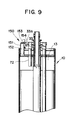
- the position sensing device 150 is attached to the slidable wing drill bit supporting member 13 and actuated by a float release pin 33A implanted in the connecting rod pin 33. as shown in Fig. 9.
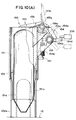
- the sensing device 150 is roughly made up of a float capsule 151 in which a float 152 is inserted, a float holding plate 153, and a holding plate releasing member 154. The mechanism will be described in further detail with reference to Fig. 10(A).
- the float 152 is of cylindrical rocket type, which includes three vertical wings 152a. This float 152 is encapsulated within the float, capsule 151 on the ground.
- the float capsule 151 includes three side apertures 151a so as to introduce water or slurry thereinto.
- the float 152 to which an upward floating power is always applied under water or slurry is forcibly stopped by the float holding plate 153.
- the holding plate 153 is pivotably supported by a first shaft 153 a supported by two first vertical plates 155 fixed to the outer surface of the float capsule 151 at the uppermost position. This holding platae 153 is urged by a first spring 153b clockwise.
- a second vertical plate 156 is fixed to the outer surface of the float capsule 151 in parallel with the first vertical plates 155.
- a plurality of spring holes 156a are formed in circular arc fashion on the second vertical plate 156, so that an elastaic spring force applied to the holding plate 153 can be adjusted by appropriately selecting a hole to which one end of the first spring 153b is fitted.
- One end of the holding plate 153 extends over the top of the float 152 as shown to depress the float when set.
- the holding plate releasing member 154 is also pivotably supported by a second shaft 154a supported by the two first vertical plataes 155 near the first shaft 153 a.
- the holding plate releasing member 154 is urged by a second spring 154b counterclockwise.
- This releasing member 154 includes a locking end portion 154c engageable with the other end of the float holding platae 153 and an arm portion 154d engageable with the float release pin 33A implanted in the connecting rod pin 33.
- one end of the second spring 154b is hooked to one end portion of the releasing member 154.
- the other end of the second spring 154b is fixed by a spring piece 157 provided at the outer surface of the float capsule 151.
- the reference numeral 154e shown in Fig. 10(A) denotes a stopper pin against the releasing member 154 urged counterclockwise by the second spring 154b.
- the float 152 can readily be inserted into the float capsule 151.
- the float holding plate 153 is rotated by the operator hand counterclockwise against the first spring 156a so that the holding plate 153 holds the top of the capsule 151.
- the releasing member 154 is urged counterclockwise by the second spring 154b, the holding plate 153 is automatically locked by the releasing member 154, as shown by the solid lines in Fig. 10(A). In this case, the releasing member 154 is stopped by the stopper pin 154e.
- the excavating bucket is lowered into a straight pile bore to excavate an under reamed part of the pile bore.
- the holding member 153 is released. Therefore, the holding member 153 rotates clockwise by the elastic force of the first spring 153b as shown by the dot-dot dashed lines in Fig. 10(A), so that the float comes to the water surface due to the floating power.
- the position sensing device is so arranged that the float may be released when the two wing drill bits reach at their lowermost position.
- the slidable wing drill bits are housed within the bucket body and arranged so as to be moved downward and outward along the guide rails for excavation of an under reamed part of a pile bore, and since the side apertures are formed in the bucket body so as to be opened or closed in synchronization with the sliding movement of the drill bits, it is possible to excavate an under reamed part of a pile bore by the use of a bucket.
- pivotable scraper is provided under the drill bits so as to be operable when the drill bits are rotated in the reverse direction and since the fixed scraper is further provided on the bucket bottom plate to effectively move the excavated soil into the bucket body through the openable bottom apertures, it is possible to effectively move the excavated soil into the bucket body for removal of soil from the excavated pile bore.
Abstract
Description
- The present invention relates generally to an under reaming pile bore excavating bucket and the method of excavating an under reamed part of a pile bore, and more particularly to an excavating bucket such that an under reamed part of a pile bore can be excavated and further the excavated soil can be moved into the bucket body for easy removal of soil. The bucket includes, in particular, a plurality of slidable wing bits housed within a bucket and moved downward and extended outward along guide rails at the bottom of an already excavated straight pile bore.
- In executing pile foundations in construction works, a method of drilling earth (earth drill method) is conventionally adopted. In this earth drill- method. a rotatable bucket is used for excavating a straight pile bore and moving the excavated soil from the excavated bore to the outside. The bucket is attached to the lowermost position of a kelly rotatably suspended by a crane. The bucket includes a bottom plate provided with a plurality of drill bits. When the bucket is rotated by the kelly, the soil excavated by the drill bits are taken into the bucket. The bucket filled with the excavated soil is raised by the crane and the soil in the bucket is removed by opening the bottom plate thereof.
- By the way, as an economical method of executing pile foundations, an under reamed bore foundation is well known, in which a larger diameter bore is excavated at the bottom of a straight pile bore to increase the pile end bearing capability against a vertical load applied to the pile.
- In the earth drill method using a bucket, however, it is rather difficult to realize an under reaming pile bore excavating bucket of simple configuration and a method of executing the same in simple steps.
- A more detailed description of the prior-art pile bore excavating bucket will be made hereinafter with reference to the attached drawings under DETAILED DESCRIPTION OF THE INVENTION.
- With these problems in mind therefore, it is the primary object of the present invention to provide an under reaming pile bore excavating bucket of simple configuration and a method of excavating an under reamed part of a pile bore in simple steps by the use of a bucket.
- To achieve the above-mentioned object, the under reaming pile bore excavating bucket according to the present invention comprises: (a) a bucket body formed with side apertures near the lower part thereof; (b) a bucket bottom plate attached to the bottom thereof so as to open or close the bottom and formed with openable bottom apertures for taking excavated soil into the bucket body; (c) an outer pipe fixed to the bucket body at the center of the bucket body; (d) a drive shaft telescopically engaged with the outer pipe for rotating the bucket body when an excavating torque is applied, the drive shaft sliding downward when rotated in one direction and upward when rotated in the other direction: (e) a bucket cover engaged with the drive shaft and assembled with the bucket body so as to open the side apertures of the bucket body when rotated in one direction and close the side apertures when rotated in the other direction by the drive shaft; (f) a plurality of guide rails fixed to said outer pipe at an inclined angle with respect to the axis of the outer pipe; (g) a plurality of connecting rod, each of one ends of the rods being pivotably connected to the drive shaft, respectively: and (h) a plurality of slidable wing bits pivotably connected to each of the other ends of the connecting rods, respectively and slidably mounted on the guide rails at an appropriate bit angle to excavate an under reamed part of a pile bore.
- In the excavating bucket thus constructed, when the drive shaft is driven in one direction, the side apertures of the bucket body are first opened and then the wing drill bits are rotated in-the same direction together with the bucket body and further moved downward and outward along the guide rails passing through the side apertures now opened by a force of gravity applied thereto to excavate an under reamed part of a pile bore; the excavated soil is taken into the bucket body through the opened side apertures and the openable bottom apertures; and when the drive shaft is driven in the other direction, the wing drill bits are moved upward and inward through the side apertures along the guide rails by a torque applied to the drive shaft and lastly the side apertures of the bucket body are closed to raise the bucket filled with soil.
- Further, to achieve the above-mentioned object. the method of excavating an under reamed part of a pile bore according to the present invention comprises the following steps of: (a) excavating a straight pile bore; (b) lowering an excavating bucket to the bottom of the straight pile bore; (c) closing a bucket bottom plate when the bucket reaches the bottom of the straight pile bore; (d) rotating a drive shaft in the forward direction to first open side apertures of the bucket and then to drive wing drill bits together with the bucket body in such a way that rotated wing drill bits move downward and extend outward along guide rails passing through the opened side apertures to excavate the under reamed part of the pile bore, while taking excavated soil into the bucket body through the side apertures of the bucket body and the openable bottom apertures of the bucket bottom plate: (e) if the wing drill bits reach their lowermost position, rotating the drive shaft in the reverse direction to move the wing drill bits upward and contract them inward along the guide rails passing through the opened side apertures to house again the drill bits within the bucket body while moving excavated soil to under the bucket and taking the moved soil into the bucket through the openable bottom apertures; (f) closing the side apertures by the bucket cover; (g) raising the excavating bucket onto the ground; and (h) opening the openable bucket bottom plate to remove the excavated soil within the bucket body to the outside.
- The features and advantages of the under-reaming pile bore excavating bucket according to the present invention will be more clearly appreciated from the following description taken in conjunction with the accompanying drawings in which like reference numerals designate the same or similar elements or sections throughout the figures thereof and in which:
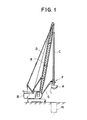
- Fig. 1 is a general view showing a crane which drives a pile bore excavating bucket, for assistance in explaining earth drill method adopted for construction works;
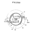
- Fig. 2(A) is a lateral cross sectional view, partly in top view, of a first embodiment of the under reaming pile bore excavating bucket according to the present invention, in which two wing drill bits are extended outward from a bucket;
- Fig. 2(B) is a longitudinal cross sectional view, partly in side view, of the first embodiment of the pile bore excavating bucket according to the present invention, taken along the line II(B) - II(B) shown in Fig. 2(A), in which two wing drill bits are extended outward from the bucket;
- Fig. 3(A) is a lateral cross sectional view, partly in top view, of the first embodiment of the pile bore excavating bucket according to the present invention, in which the two wing drill bits are housed within the bucket;
- Fig. 3(B) is a longitudinal cross sectional view, partly in side view, of the first embodiment of the pile bore excavating bucket according to the present invention, taken along the line III(B) - III(B) shown in Fig. 3 (A), in which the two wing drill bits are housed within the bucket;
- Fig. 4(A) is a top view showing a bucket body adopted for the first embodiment of the excavating bucket according to the present invention;
- Fig. 4.(B) is a first longitudinal cross sectional view, partly in side view, showing the bucket body adopted for the first embodiment of the excavating bucket according to the present invention, taken along the line IV(B) - IV(B) shown in Fig. 4.(A):
- Fig. 4(c) is a second longitudinal cross sectional view, partly in side view, showing the bucket body adopted for the first embodiment of the excavating bucket according to the present invention, taken along the line IV(C) - IV(C) shown in Fig. 4(A);
- Fig. 4.(D) is a bottom view showing a bucket bottom plate adopted for the first embodiment of the excavating bucket according to the present invention;
- Fig. 5 (A) is a top view showing a splined drive shaft adopted for the first embodiment of the excavating bucket according to the present invention:
- Fig. 5(B) is a side view showing the splined drive shaft having a plurality of outer helical spline tongues adopted for the first embodiment of the excavating bucket according to the present invention;
- Fig. 5(C) is an opened-out view of an outer pipe having a plurality of helical. spline tongues and grooves formed on the inner circumferential surface thereof (shown by solid lines) and a drive shaft having a plurality of helical spline tongue formed on the outer circumferential surface thereof (shown by dashed lines);
- Fig. 5(D) is a lateral cross sectional view showing the spline engagement relationship between the outer helical tongues of the drive shaft and the inner helical tongues of the outer pipe;
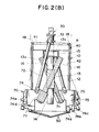
- Fig. 6(A) is a top view showing a bucket. cover adopted for the first embodiment of the excavating bucket according to the present invention;
- Fig. 6(B) is a side view showing the bucket cover adopted for the first embodiment of the excavating bucket according to the present invention;
- Fig. 7 (A) is a lateral cross sectional view, partly in top view, of a second embodiment of the under reaming pile bore excavating bucket according to the present invention, in which the two wing drill bits are extended outward from a bucket;
- Fig. 7(B) is a cross sectional slide view, partly in sude view, showing a pivotable scraper attached to the wing bits adopted for the second embodiment of the excavating bucket according to the present invention, taken along the line VII(B) - VII(B) shown in Fig. 7(A);
- Fig. 7(C) is a bottom view showing a fixed scraper attached to the bucket bottom plate adopted for the second embodiment of the excavating bucket according to the present invention:
- Fig. 8(A) is a longitudinal cross sectional view, partly in side view, of the second embodiment of the excavating bucket according to the present invention, taken along the line VIII(A) - VIII(8) shown in Fig. 7(A), in which the two wing drill bits are extended outward from the bucket body;
- Fig. 8(B) is a side view of the second embodiment of the excavating bucket according to the present invention, in which the two wing drill bits are housed within the bucket body;
- Fig. 8(C) is a longitudinal cross sectional view, partly in side view, of the second embodiment of the excavating bucket according to the present invention. take along the line VIII(C) - VIII(C) shown in Fig. 7(A), in which the two wing drill bits are extended outward from the bucket;
- Fig. 9 is a fragmentary longitudinal cross sectional view, partly in side view, of the second embodiment of the excavating bucket according to the present invention, on which a submersible position sensing device according to the present invention is mounted;
- Fig. 10(A) is an enlarged side view, partially in cross section, showing the submersible position sensing device mounted on the second embodiment of the excavating bucket according to the present invention; and
- Fig. 10(B) is an enlarged top view of the submersible position sensing device shown in Fig. 10(A).
- To facilitate understanding of the present invention, a brief reference will be made to a prior-art method of excavating a-pile bore in construction works for executing pile foundations, that is, so-called earth drill method.
- In Fig. 1, an excavating bucket A is supported by a crane B. The bucket A is attached to the lowermost end of a kelly C. This kelly C is.connected to a rope D supported by a boom E of the crane B. Further, the kelly C is rotated by a driving unit F supported by the crane B through an arm G. The bucket A is provided with a plurality of excavating bits arranged at the conical bottom plate thereof. The excavated soil under the bucket is taken into the rotating bucket through openable bottom apertures formed in the bottom plate during excavation. The bottom plate is opened or closed by means of an appropriate hooking mechanism for removal of excavated soil within the bucket.
- In operation, when the bucket A is rotated by the kelly C, a rotational force and a thrust are applied from the kelly C to the bucket A simultaneously, so that the drill bits excavate a straight pile bore H and the excavated soil is moved into the bucket through appropriate openable apertures formed in the bottom plate. When the bucket A is filled with excavated soil, the bucket A is raised and moved by the crane B onto a bed of a dump truck, the excavated soil being dropped onto the dump truck bed by opening the bottom plate of the bucket A.
- By the way, to increase the pile end bearing capability against a vertical load applied to the pile, it is preferable to use an under reamed pile bore foundation, in which a larger diameter bore is excavated at the bottom of a straight pile bore.
- In the conventional excavating bucket A as described above, it is impossible to excavate an under reamed pile bore.
- In view of the above description, reference is now made to a first embodiment of an under reaming pile bore excavating bucket according to the present invention with reference to the attached drawings. Figs. 2(A) and 2(B) show a state where a plurality of wing drill bits are extended outward to excavate an under reamed part of a pile bore; Figs. 3 (A) and 3(B) show a state where a plurality of wing bits are retracted inward within the bucket; Figs. 4(A), 4.(B), 4:(C) and 4(D) show essential elements of the excavating bucket according to the present invention.
- The excavating bucket is roughly made up of a
cylindrical bucket body 10, a splineddrive shaft 30, apivotable bucket cover 40, a conicalbucket bottom plate 50, and two slidablewing drill bits 70. - The
cylindrical bucket body 10 is formed with twoside apertures 12 of rectangular shape, as best shown in Fig. 4(B), in the cylindrical surface thereof in diametrically opposed positional relationship with respect to the center of the-bucket body 10. Through the two openedside apertures 12, the two slidablewing drill bits 60 are extended outward, as described in more detail later. - Near the uppermost position of the
cylindrical bucket body 10, a wingbit supporting member 13 of rectangular cross section is fixed by welding to the inner circumferential surface of thebucket body 10 extending radially within thebody 10, as best shown in Fig. 4(A). In this supportingmember 13, a central hole and a pair ofslots 13 a are formed, also as best shown in Fig. 4.(A). In the central hole of the supportingmember 13, anouter pipe 14 havinghelical spline tongues 14a andgrooves 14b, as shown in Fig. 5(D), is fixed by welding to the supportingmember 13 extending axially into thebucket body 10. - At the outer middle portion of the
outer pipe 14 within thecylindrical bucket body 10, asquare pipe 15 is fixed by welding. On both the outer surfaces of thesquare pipe 15, twoguide rails 16 of T-shaped cross section are fixed respectively by welding extending downward and outward at an appropriate skew angle θ with respect to theouter pipe 14 so as to cross the axis of thecylindrical bucket body 10 in x-shaped fashion, as shown in Fig. 3(B). Along these two guide rails. the two slidable wing drill bits 70 (described later) are moved up and down or extended downward or retracted upward. - Into the above-mentioned
outer pipe 14, thesplined drive shaft 30 is telescopically engaged rctatably and slidably in the axial direction thereof. As depicted in Fig. 5(B), the splined drive shaft 19 is formed with twoflanges 31, being spaced from each other. Between these twoflanges 31, anannular bushing 32 is rotatably disposed. On the outer surface of theannular bushing 32, two connecting rod pins 33 are fixed by welding or implanted in the diametrically opposite direction, as best seen in Fig. 5 (A). Thesplined drive shaft 30 has two helicalouter tongues 30a and two helicalouter grooves 30b. Further, the top 30a of thedrive shaft 30 is connected to the kelly C. - The
pivotable bucket cover 40 is made up of acover supporting frame 41 and a pair of cylindrical arc shapedmembers 42 connected by thesupport frame 41 at its uppermost position. Further, at the center of thesupport frame 41, acentral bushing 43 havingsplines 43 a is provided so that thespline drive shaft 30 can be engaged therewith, as best shown in Fig. 6(A). The abovepivotable bucket cover 40 is inserted into the inner circumference of the bucket body from above and thecover supporting frame 41 is placed onto the drillbit supporting member 13 as shown in Figs. 2(B) and 3(B). Further, after having been placed onto thebit supporting member 13, thecover supporting frame 41 is held by a pair ofcircular arc members 18 attached by bolts and nuts to the inner circumferential surface of thebacket body 10 at its top end, as shown in Figs. 2(B) and 3(B), to prevent the assembled bucket cover 40 from being removed from thebucket body 10. Thebucket cover 40 opens the twoside apertures 12 of thebucket body 10 when pivoted in one direction (clockwise) but closes the twoside apertures 12 when pivoted in the other direction (counterclockwise). In other words, the cylindrical arc width of themember 42 roughly corresponds to that of theside aperture 12 of thebucket body 10. - The conical
bucket bottom plate 50 is attached to the bottom of thebucket body 10 so as to be opened or closed, as best shown in Fig. 4(D). Thebottom plate 50 is supported by ahinge 53 at one hand and by a hook mechanism at the other hand. In more detail, afirst hinge plate 51 shown in Fig. 4(C) is fixed by welding to the periphery of thebottom plate 50. Asecond hinge plate 52 is fixed by welding to the inner circumference of thebucket body 10 near its lowermost position. Ahinge pin 53 is inserted through the first andsecond hinge plates bottom plate 50 can be opened or closed with thishinge pin 53 as its axis. - At the diametrically opposite position of the
hinge pin 53, a hooking mechanism is provided. The hooking mechanism is made up of anoperation rod 55 having anengaging plate member 56 at the lowermost position, an engagingpawl member 57 and areturn spring 58, as depicted in Fig. 4(C). Theoperation rod 55 is pivotably supported near the inner circumference of thebucket body 10 so as to be operable from the outside and is urged in one direction by the elastic force of areturn spring 58. - The engaging
pawl member 57 is fixed by welding to thebottom plate 50. - When the
bucket body 10 is lowered into a pile bore and therefore thebottom plate 50 is brought into contact with the bottom of a pile bore, thebottom plate 50 begins to be closed gradually. In this connection, thebottom plate 50 can more easily be closed when thebucket body 10 is pivoted or rotated appropriately. When thebottom plate 50 is almost closed, the engagingpawl member 57 urges theengaging plate member 56 in one direction against the elastic force of thereturn spring 58 to an engagement position where theplate member 56 returns. At this position,pawl member 57 engages with theplate member 56 to lock thebottom plate 50 to thebucket body 10. Further, to open thebottom plate 50 for removal of soil, theoperation rod 55 is pivoted against the force of thereturn spring 58 to disengage theplate member 56 from thepawl member 57, so that thebottom plate 50 can be opened downward by its weight. - Further, a pair of
bottom apertures 59 are formed in thebottom plate 50 as best shown in Fig. 4.(D). Theseapertures 59 are closed from the inside of thebucket body 10 bycover plates 60, respectively, supported by hinges 61. Since thecover plates 60 are placed inside thebucket body 10, usually theseapertures 59 are closed; however, it is possible to open these apertures for moving soil or muck remaining at the bottom of a pile bore into thebucket body 10 when thebucket body 10 is rotated in the direction opposite to excavation. - The two slidable
wing drill bits 70 having a plurality ofbit teeth slidable blocks 71, respectively, which slidably engage with the T-shaped guide rails 16. Further, thewing drill bits 70 are connected to thespline drive shaft 30 by a connectingrod 72. One end of the connectingrod 72 is pivotably supported by thepin 33 attached to theannular bushing 32; the other end of the connectingrod 72 is also pivotably supported by apin 74 attached to thewing drill bits 70, respectively. Further, since a pair ofslots 13a are formed in the wingbit supporting member 13 and each of the upper end of the connectingrod 72 is inserted in theslot 13a, the connectingrod 72 is movable within theslot 13 a when moved up and down or inward and outward by thesplined drive shaft 30. - Further, since the guide rails 16 are arranged in X-shaped fashion within the
bucket body 10 as shown in Figs. 2(B) and 3(B), it is possible to effectively house the wing drill bits within thebucket body 10 and to extend them out of thebucket body 10. - In this first embodiment, a plurality of
bottom bit teeth wing bit plate 75 to excavate the bottom of a pile bore. and a plurality ofside bit teeth wing bit plate 75 to excavate the under reamed part of a pile bore, as depicted in Fig. 2(B). - With reference to Figs. 5(B), (C) and (D), the spline engagement between the
splined drive shaft 30 and theouter pipe 14 will be described hereinbelow in further detail. - The
splined drive shaft 30 is formed with two helicalouter tongues 30a and two helicalouter grooves 30b. The angular width of theouter tongues 30a is about 75 degrees around theshaft 30 and the angular width of theouter grooves 30b is about 105 degrees. Therefore, the angular ratio of tongue and groove is 75 to 105 or 5 to 7. - The
outer pipe 14 is formed with two helicalinner tongues 14a and the two helicalinner grooves 14b. The angular width of theinner tongue 14a is about 60 degrees around theouter pipe 14 and the angular width of theinner groove 14b is about 120 degrees. Therefore, the angular ratio of tongue and groove is 60 to 120 or 1 to 2. Further, near the top of theouter pipe 14, there are formed two horizontal steppedcutout portions 14A, the angular width of which is about 45 degrees, as depicte in the opened-view of Fig. 5(C). Since thesplined drive shaft 30 is engaged with theouter pipe 14 in spline engagement, when thesplined drive shaft 30 is rotated clockwise by the kelly C (shown in Fig. 1), the outer pipe 14 (bucket body) is also rotated clockwise. Further, thedrive shaft 30 is telescopically inserted into theouter pipe 14. - The splines are designed so as to have a common skew angle with respect to the axial direction of the
drive shaft 30 or theouter pipe 14. - The skew angle γ can be obtained readily by using the following simple expressions, so that a downward force will cancel the frictional force produced between the
drive shaft 30 and theouter pipe 14, while transmitting a torque from thesplined drive shaft 30 to the outer pipe 14:
R = µQ or µ = R/Q = tan y
where Q is the normal component of the rotation force P, R is the tangential component, and µ is a coefficient of friction. - Further, if this skew angle is excessively large, the
bucket body 10 may be moved upward while rotating; if excessively small, it is impossible to effectively slide thedrive shaft 30 into theouter pipe 14 or thebucket body 10 without friction. Therefore, an appropriate angle (14 to 16 degrees) is required. In this connection, the splines are made of carbon steel or copper alloy. Thedrive shaft 30 is moved in the downward direction by the aid of the weight of kelly c or a thrust applied to the kelly. - Since the spline engagement is arranged as described above, when the
splined drive shaft 30 is rotated in the forward direction (clockwise when seen from the top in Fig. 2(B), 3(B), or 5(B)) to excavate an under reamed part of a pile bore, the outerhelical tongues 30a engage with the innerhelical grooves 14b, as best shown in the opened-out view of Fig. 5(C), to rotate theouter pipe 14 also in the forward direction and further to drive thedrive shaft 30 in the downward direction. - In more detail, in the forward direction, the sloped side surfaces 30a-1 of the
outer tongues 30a of thedrive shaft 30 are brought into contact with the sloped side surfaces 14a-1 of theinner tongues 14a. Therefore, the rotation force P is divided into the normal component Q to rotate theouter pipe 14 clockwise and the tangential component R to move thedrive shaft 30 itself smoothly downward. Since theouter pipe 14 is fixed to thebucket body 10, thewing drill bits 70 rotate clockwise to excavate soil. When the tangential component R is roughly equal to the friction between the two, since thedrive shaft 30 is connected to thewing drill bits 70 via the connectingrod 72, thewing bits 70 move smoothly downward and outward along theguide rail 16 to widen the diameter of the under reamed part of a pile bore. - On the other hand, when the
splined drive shaft 30 is rotated in the reverse direction (counterclockwise when seen from the top in Fig. 2(B), 3(B), or 5(B)) to raise thewing drill bits 70, the outerhelical tongues 30a engage with the innerhelical grooves 14b, as best shown in the opened-out view of Fig. 5(C), to rotate theouter pipe 14 also in the reverse direction and further drive thedrive shaft 30 in the upward direction. - In more detail, in the reverse direction, the sloped side surfaces 30a-2 of the
outer tongues 30a of thedrive shaft 30 are brought into contact with the sloped side surfaces 14a-2 of theinner tongues 14a. Therefore, the rotation force P' is divided into the normal component Q' to rotate theouter pipe 14 counterclockwise and the tangential component R' to move thedrive shaft 30 itself smoothly upward. Since theouter pipe 14 is fixed to thebucket body 10, thewing drill bits 70 rotate counterclockwise without excavating soil. Since thedrive shaft 30 is connected to thewing drill bits 70 via the connectingrod 72, thewing bits 70 moves smoothly upward and inward along theguide rail 16 into thebucket body 10. - Further, the
outer tongues 30a of thedrive shaft 30 reach near the top position, thelower end surfaces 30a-3 of theouter tongues 30a of thedrive shaft 30 are engaged with steppedcutout portions 14a-4 of theinner tongues 14a of theouter pipe 14 to close theside apertures 12. Thereafter, sloped side surfaces 30a-2 of theouter tongues 30a- are brought into contact with the sloped side surfaces 14a-3 of theinner tongues 14a. However, when the sloped side surfaces 30a-2 are brought into contact with the sloped side surfaces 14a-3, the slidabledrill wing bits 70 are stopped by appropriate stop members (not shown) fixed in position to the wingbit supporting member 13 of rectangular cross section. - Further, the
side apertures 12 of thebucket body 10 are closed when theouter tongues 30a of thedrive shaft 30 engages with the horizontal steppedcutout portions 14a-4 of theinner tongues 14a of theouter pipe 14. In more accuracy. since the angular width of theside apertures 12 is about 45 degrees, theapertures 12 begin to be closed when theouter tongues 30a reach the edge of thecutout portion 14a-4 or the edge surfaces 14a-2 of theinner tongues 14a at the uppermost position. - The operation of opening and closing the
bucket cover 40 will be described hereinbelow. Since twoinner tongues 43a are formed in the inner circumferential surface of thecentral bushing 43 of thecover supporting frame 41, as best shown in Fig. 6(A), and are engageable with theouter grooves 30b of thedrive shaft 30, when thedrive shaft 30 rotates, the bucket cover 40- is also rotated together therewith. Further, thebucket cover 40 is placed on the supportingframe 13 and is held by twocircular arc members 18 attached to the uppermost position of thebucket body 10 as shown in Fig. 2(B) or 3(B). Therefore, even if rotated, thebucket cover 40 is neither raised or lowered, but rotated in either direction by a predetermined angle together with thedrive shaft 30. - Here, it should be noted that since the two cylindrical arc shaped
members 42 of thebucket cover 40 are inserted from top of the-bucket body 10 into the two arched spaces surrounded by the inner circumference of thebucket body 10 and the straight end surface of the wingbit supporting member 13, the bucket cover is rotatable only within the above arched spaces as shown by dot-dot dashed lines in Fig. 4(A). Further, the angular width of theside apertures 12 of thebucket body 10 is approximately 45 degrees as shown in Fig. 2(A) or 2(B). - With reference to Fig. 5(C) again, when the
outer tongues 30a of thedrive shaft 30 are engaged with theinner tongues 14a of theouter pipe 14 as shown by the dashed line in Fig. 5(C), thebucket cover 40 begins to close theside apertures 12 of thebucket body 10. However, when thedrive shaft 30 is rotated in the forward direction (clockwise in Fig. 4A) to excavate a pile bore, theside apertures 12 are first opened and then the sloped edge surfaces 30a-1 of theouter tongues 30a of thedrive shaft 30 are brought into contact with the sl.oped edge surfaces 14a-1 of theinner tongues 14a of theouter pipe 14 to transmit a rotational power from thedrive shaft 30 to theouter pipe 14, that is, to thebucket body 10. Further, the difference (45 degrees) in angular width between theouter tongues 30a (75 degrees) and theinner grooves 14b (120 degrees) is an idle angular space for driving theouter pipe 14 by thedrive shaft 14. - The method and operation of excavating an under reamed pile bore by the use of the excavating bucket according to the present invention will be described hereinbelow.
- With reference to Fig. 1, a straight pile bore H is first excavated to a predetermined depth by use of an ordinary bucket excavator provided with a plurality of fixed drill bits at the bottom thereof. In this case, the ordinary bucket excavator is suspended by a kelly C moved up and down by a crane, and rotated by a driving unit F supported by an arm G attached to the crane B. If the straight pile bore H is excavated to a predetermined depth, the ordinary bucket excavator is raised to the outside and exchanged with the excavating bucket according to the present invention. At this time, the
splined drive shaft 30 is raised to its uppermost position and therefore thebucket cover 40 is closed, the twowing drill bits 70 being housed within thebucket body 10, as shown in Figs. 3(A) and 3(B). The top 30A of thesplined drive shaft 30 is connected to the lower end of the kelly C. The excavating bucket is lowered by the crane to the bottom of the straight pile bore. At this time, even if the conicalbucket bottom plate 50 is opened, when the bucket is lowered, thebottom plate 50 is closed automatically, owing to the hookingmechanism bucket body 10. - When the
splined drive shaft 30 is rotated clockwise (in the forward direction) in Fig. 3(A), thebottom end surfaces 30 a-3 of theouter tongues 30 a of thedrive shaft 30 slide on the horizontal steppedcutout portion 14a-4 of theinner tongues 14a of theouter pipe 14 to open theside apertures 12 of thebucket body 10 and further the slopedside end surfaces 30 a-1 of thedrive shaft 30 are brought into contact with the sloped side end surfaces 14a-1 of theinner tongues 14a of theouter pipe 14, as depicted in Fig. 5(C). During this operation, theside apertures 12 closed by thebucket cover 40 are opened because thedrive shaft 30 rotates thecover 40 simultaneously clockwise until the side edge of the cylindrical arc shapedmember 42 is brought into contact with one end surface of the supportingframe 13 as shown in Fig. 4(A). - When the
drive shaft 30 is further rotated, thedrive shaft 30 rotates theouter pipe 14, that is, thebucket body 10, because a normal component Q is applied from thedrive shaft 30 to theouter pipe 14 via the spline engagement. Simultaneously, the drive.shaft 30 itself slides down into theouter pipe 14, because a tangential component R is generated beyond a friction force produced between thedrive shaft 30 and theouter pipe 14. In other words, thesplined drive shaft 30 moves telescopically into theouter pipe 14 while rotating thebucket body 10. - As the
drive shaft 30 moves in the downward direction, the twoslidable wing bits 70 extend gradually outwardly and downwardly along the guide rails 16 to excavate the under reamed part of the pile bore. The excavated soil is moved into thebucket body 10 directly through theside apertures 12 of thebucket body 10 or through thebottom apertures 59 of theconical bottom plate 50 by forcibly opening thecover plate 60 hinged against thebottom plate 50 from the inside. When thewing drill bits 70 slide up to its lowermost position, an under reamed part is completely excavated in addition to the straight pile bore. - After the excavation has been completed, the
splined drive shaft 30 is rotated counterclockwise (in the reverse direction) to move the slidablewing drill bits 70 upward and inward. With reference to Fig. 5(C), the splined side end surfaces 30a-2 of theouter tongues 30a of thedrive shaft 30 are brought into contact with the splined side end surfaces 14a-2 of theinner tongues 14a of theouter pipe 14. During this operation, thedrive shaft 30 is rotated idle. - When the
drive shaft 30 is further rotated counterclockwise and moved upward by the kelly, thedrive shaft 30 is readily extracted from theouter pipe 14. Therefore, the twoslidable wing bits 70 move gradually inwardly and upwardly along theguide rail 16 into thebucket body 10. At the end of this operation, the.lower end surfaces 30a-3 of theouter tongues 30a of thedrive shaft 30 are engaged with the horizontal steppedcutout portions 14a-4 of theinner tongues 14a of theouter pipe 14 and further thedrive shaft 30 is rotated counterclockwise until the sloped side end surfaces 30a-2 of theouter tongues 30a are brought into contact with the sloped side end surfaces 14a-3 of theinner tongues 14a to close theside apertures 12 of thebucket body 10. Thedrive shaft 30 rotates thebucket cover 40 simultaneously counterclockwise until the side edge of the cylindrical are shapedmembers 42 are brought into contact with the supportingframe 13, as shown in Fig. 4(A). - Thereafter, the
bucket body 10 including excavated soil is raised from the pile bore and then moved onto a dump truck. By operating theoperation rod 55 shown in Fig. (C) in order to release the hook mechanism, theconical bottom plate 50 is opened, so that soil is discharged from thebucket body 10 onto a bed of the truck. - With reference to Figs. 7(A), (B), (C) and Figs. 8(A), (B), (C), a second embodiment of an under reaming pile bore excavating bucket according to the present invention will be described hereinbelow. The features of the second embodiment is to provide two slidable wing drill bits of plough shape having a pivotable scraper respectively and further to form the bucket bottom plate with a fixed scraper for easily scraping and gathering the excavated soil.
- As best shown in Fig. 8(A), the slidable
wing drill bit 100 includes a plough shapedbit plate 101 fixed to theslidable block 71 which slidably engages with the T-shapedguide rail 16. Thebit plate 101 has a roughlyflat back surface 101a, an arcuateouter side surface 101b and anarcuate bottom surface 101c. Therefore, while thebucket body 10 is lowered to excavate the under-reamed part of a pile bore, it is possible to effectively catch excavated soil and further to move it into thebucket body 10 through the openedapertures 12. - A plurality of
bottom bit teeth arcuate bottom surface 101c to excavate the bottom of a pile bore. A plurality ofside bit teeth outer side surface 101b to excavate the under reamed part of a pile bore. - The lowermost edge of the
bottom surface 101c is aligned on the extended line of the conical surface of thebucket bottom plate 50, when theslidable wing bit 100 is lowered to its lowermost position. - Although not shown clearly in Fig. 8(A), but as shown in Figs. 7(B) and 8(C), a
pivotable scraper 102 is provided between thebottom surface 101c and theback surface 101a of the plough shapedbit plate 101. Thescraper 102 is pivotably supported by apin 103 fixed to a ascraper plate 104. Further, thereference numeral 105 in Fig. 7(B) is a scraper stopper plate. - When the
drill wing bits 100 are rotated clockwise to excavate a pile bore, thescraper 103 pivotes upward as shown by the dot-dot dashed lines in Fig. 7 (B) without preventing excavation by thebit teeth drill wing bits 100 begin to be rotated counterclockwise to raise thebucket body 10, thescraper 103 pivotes downward as shown by the solid lines, being brought into contact with thescraper stopper plate 105, to scrape up excavated soil or muck at the lowermost position of the bucket body within a pile bore now excavated. The scraped soil is moved into thebucket body 10 through thebottom apertures 59 formed in thebucket bottom plate 50. - In this second embodiment, a fixed
scraper 110 is additionally arranged on the outer surface of thebucket bottom plate 50, as shown in Fig. 7(C). The fixedscraper 110 extends radially along the opened edges of thebottom apertures 59. Therefore, themovable scraper 102 scrapes downwards the excavated soil to the center of thebottom plate 50, and the scraped soil is further moved into thebucket body 10 through thebottom apertures 59 by the aid of the fixedscraper 110. - Further, in this second embodiment, as shown in Fig. 8(B), a plurality of
circular windows 20 are formed in the cylindrical surface of thebucket body 10 in order to remove water or slurry therethrough. Additionally, ametal net 21 is provided for only alowest window 20a, because there may exist earth and sand near the bottom of thebucket body 10. - The structual features and functional effects of this second embodiment other than those described above are substantially the same as is the case with the first embodiment previously described and any detailed description of them is believed to be unnecessary. The reference numerals have been retained for similar parts which have the same functions.
- By the way, the under reaming pile bore excavating bucket according to the present invention is applicable to both dry and wet earth drill method in construction works.
- In the wet earth drill method, a pile bore being excavated is filled with water or slurry, that is, the bucket is driven under the water. Therefore, it is impossible to confirm that the slidable wing bits are completely lowered to their lowermost position. In other words, it is impossible to recognize that a desired under reamed part of a pile bore is perfectly excavated. To overcome the above-mentioned drawbacks, conventionally, submersible limit switches or position sensors are used for detecting that the excavator has excavated a pile bore to a desired depth. A signal detected by the switch or sensor is sent to a- detection device equipped on the ground to indicate that the excavator should be raised.
- In the prior-art submersible switches or sensors for detecting a desired position of an excavator under water, however, since these switches or sensors are operated under water, durability against water and pressure are required for electrical parts used for the switches or sensor and the wires connecting between the switches and the ground detection device, in particular, for the mechanical joint sections.
- To overcome the above mentioned shortcomings, in the excavating bucket according to the present invention, a simple mechanical position sensing device using a float is incorporated therewith. In this device, when the excavating bucket has completely excavated the under reamed part of a pile bore, a float is released from the sensing device to the water level, so that the operator can recognize the completion of excavation.
- With reference to Figs. 9 and 10 (A), (B), a float type position sensing device according to the present invention will be described hereinbelow. The
position sensing device 150 is attached to the slidable wing drillbit supporting member 13 and actuated by afloat release pin 33A implanted in the connectingrod pin 33. as shown in Fig. 9. - The
sensing device 150 is roughly made up of afloat capsule 151 in which afloat 152 is inserted, afloat holding plate 153, and a holdingplate releasing member 154. The mechanism will be described in further detail with reference to Fig. 10(A). - The
float 152 is of cylindrical rocket type, which includes threevertical wings 152a. Thisfloat 152 is encapsulated within the float,capsule 151 on the ground. Thefloat capsule 151 includes threeside apertures 151a so as to introduce water or slurry thereinto. Thefloat 152 to which an upward floating power is always applied under water or slurry is forcibly stopped by thefloat holding plate 153. The holdingplate 153 is pivotably supported by afirst shaft 153 a supported by two firstvertical plates 155 fixed to the outer surface of thefloat capsule 151 at the uppermost position. This holdingplatae 153 is urged by afirst spring 153b clockwise. Further, a secondvertical plate 156 is fixed to the outer surface of thefloat capsule 151 in parallel with the firstvertical plates 155. A plurality ofspring holes 156a are formed in circular arc fashion on the secondvertical plate 156, so that an elastaic spring force applied to the holdingplate 153 can be adjusted by appropriately selecting a hole to which one end of thefirst spring 153b is fitted. One end of the holdingplate 153 extends over the top of thefloat 152 as shown to depress the float when set. - The holding
plate releasing member 154 is also pivotably supported by asecond shaft 154a supported by the two firstvertical plataes 155 near thefirst shaft 153 a. The holdingplate releasing member 154 is urged by asecond spring 154b counterclockwise. This releasingmember 154 includes a lockingend portion 154c engageable with the other end of thefloat holding platae 153 and anarm portion 154d engageable with thefloat release pin 33A implanted in the connectingrod pin 33. Further, one end of thesecond spring 154b is hooked to one end portion of the releasingmember 154. Further, the other end of thesecond spring 154b is fixed by aspring piece 157 provided at the outer surface of thefloat capsule 151. Thereference numeral 154e shown in Fig. 10(A) denotes a stopper pin against the releasingmember 154 urged counterclockwise by thesecond spring 154b. - The operation of the
position sensing device 150 will be described hereinbelow. When the excavating bucket is on the ground, no floating power is generated. Therefore, thefloat 152 can readily be inserted into thefloat capsule 151. After having inserted the float into thecapsule 151, thefloat holding plate 153 is rotated by the operator hand counterclockwise against thefirst spring 156a so that the holdingplate 153 holds the top of thecapsule 151. In this case, since the releasingmember 154 is urged counterclockwise by thesecond spring 154b, the holdingplate 153 is automatically locked by the releasingmember 154, as shown by the solid lines in Fig. 10(A). In this case, the releasingmember 154 is stopped by thestopper pin 154e. - Then, the excavating bucket is lowered into a straight pile bore to excavate an under reamed part of the pile bore. If the two
wing drill bits 70 slide to the lowermost position, since thefloat release pin 33A implanted in the connectingrod pin 33 is brought into contact with the releasingmember 154 and further rotates the releasingmember 154 clockwise against the elastic force of thesecond spring 154b, the holdingmember 153 is released. Therefore, the holdingmember 153 rotates clockwise by the elastic force of thefirst spring 153b as shown by the dot-dot dashed lines in Fig. 10(A), so that the float comes to the water surface due to the floating power. By recognizing the float on the water surface, the operator can recognize that thewing drill bitts 70 reach the bottom, so that the excavating bucket is raised on the ground. - In the above description, the position sensing device is so arranged that the float may be released when the two wing drill bits reach at their lowermost position. However, it is also possible to detect the position at which the two wing rill bits reach the middle of the under-reaming stroke. In this case, a relatively deep capsule is used. Further, in order to detect plural strokes of the wing drill bits, it is also possible to provide a plurality of position sensing devices for the excavating bucket.
- As described above, in the under reaming pile bore excavating bucket according to the present invention, since the slidable wing drill bits are housed within the bucket body and arranged so as to be moved downward and outward along the guide rails for excavation of an under reamed part of a pile bore, and since the side apertures are formed in the bucket body so as to be opened or closed in synchronization with the sliding movement of the drill bits, it is possible to excavate an under reamed part of a pile bore by the use of a bucket.
- Further, since the pivotable scraper is provided under the drill bits so as to be operable when the drill bits are rotated in the reverse direction and since the fixed scraper is further provided on the bucket bottom plate to effectively move the excavated soil into the bucket body through the openable bottom apertures, it is possible to effectively move the excavated soil into the bucket body for removal of soil from the excavated pile bore.
- Further, since a mechanical position sensing device of float type is attached to the excavating bucket for detecting the lowermost position of drill bits. it is possible to improve the reliability and the durability of the sensing device.
- It will be understood by those skilled in the art that the foregoing description is in terms of a preferred embodiment of the present invention wherein various changes and -modifications may be made without departing from the spirit and scope of the invention, as set forth in the appended claims.
Claims (16)
whereby when said drive shaft is driven in one direction, the side apertures of said bucket body being first opened and then said wing drill bits are rotated in the same direction together with said bucket body and further moved downward and outward along said guide rails passing through the side apertures now opened by a force of gravity applied thereto to excavate an under reamed part of a pile bore, excavated soil being taken into said bucket body through the opened side apertures of said bucket body and the openable bottom apertures of said bucket bottom plate, when said drive shaft is driven in the other direction, said wing drill bits are moved upward and inward through the opened side apertures along said guide rails by a torque applied to said drive shaft and lastly the side apertures of said bucket body are closed.
Applications Claiming Priority (6)
| Application Number | Priority Date | Filing Date | Title |
|---|---|---|---|
| JP59164393A JPS6145085A (en) | 1984-08-06 | 1984-08-06 | Pit bottom drilling backet and method used in earth drill construction method |
| JP164393/84 | 1984-08-06 | ||
| JP118191/85 | 1985-05-31 | ||
| JP11819185A JPH0233833B2 (en) | 1985-05-31 | 1985-05-31 | KAKUTEIKUTSUSAKUBAKETSUTO |
| JP1985083076U JPH0327115Y2 (en) | 1985-06-01 | 1985-06-01 | |
| JP83076/85U | 1985-06-01 |
Publications (3)
| Publication Number | Publication Date |
|---|---|
| EP0171038A2 true EP0171038A2 (en) | 1986-02-12 |
| EP0171038A3 EP0171038A3 (en) | 1986-12-30 |
| EP0171038B1 EP0171038B1 (en) | 1989-10-25 |
Family
ID=27304121
Family Applications (1)
| Application Number | Title | Priority Date | Filing Date |
|---|---|---|---|
| EP85109691A Expired EP0171038B1 (en) | 1984-08-06 | 1985-08-01 | Under reaming pile bore excavating bucket and method of its excavation |
Country Status (4)
| Country | Link |
|---|---|
| US (1) | US4604818A (en) |
| EP (1) | EP0171038B1 (en) |
| KR (1) | KR910009281B1 (en) |
| DE (1) | DE3573939D1 (en) |
Cited By (4)
| Publication number | Priority date | Publication date | Assignee | Title |
|---|---|---|---|---|
| CN102677716A (en) * | 2012-05-30 | 2012-09-19 | 张永忠 | Movable arm trenching machine |
| CN102767337A (en) * | 2012-08-11 | 2012-11-07 | 威海市水利岩土工程有限公司 | Sleeve type screw pile machine drill and construction method for eliminating barriers |
| EP2770157A1 (en) * | 2013-02-26 | 2014-08-27 | Bauer Spezialtiefbau GmbH | Drilling tool and method for drilling in soil |
| CN112709277A (en) * | 2020-12-30 | 2021-04-27 | 阳光学院 | Crowded ware that expands of cylindric for civil engineering |
Families Citing this family (25)
| Publication number | Priority date | Publication date | Assignee | Title |
|---|---|---|---|---|
| DE19529617C1 (en) * | 1995-08-11 | 1996-09-19 | Zueblin Ag | Rotary drilling bucket with cylindrical steel container |
| DE19644349C1 (en) * | 1996-10-25 | 1998-04-16 | Zueblin Ag | Rock drill cylindrical cover |
| US6742596B2 (en) | 2001-05-17 | 2004-06-01 | Weatherford/Lamb, Inc. | Apparatus and methods for tubular makeup interlock |
| US6536520B1 (en) | 2000-04-17 | 2003-03-25 | Weatherford/Lamb, Inc. | Top drive casing system |
| GB9815809D0 (en) | 1998-07-22 | 1998-09-16 | Appleton Robert P | Casing running tool |
| GB2340859A (en) | 1998-08-24 | 2000-03-01 | Weatherford Lamb | Method and apparatus for facilitating the connection of tubulars using a top drive |
| ITPS990007A1 (en) * | 1999-03-11 | 2000-09-11 | I M T Spa | PERFORATION PROCEDURE FOR LARGE DIAMETER HOLES WITH HIGH DEPTH AND DRILL SUITABLE FOR IMPLEMENTING THAT PROCEDURE |
| US7325610B2 (en) | 2000-04-17 | 2008-02-05 | Weatherford/Lamb, Inc. | Methods and apparatus for handling and drilling with tubulars or casing |
| GB2364079B (en) * | 2000-06-28 | 2004-11-17 | Renovus Ltd | Drill bits |
| GB2365888B (en) | 2000-08-11 | 2002-07-24 | Renovus Ltd | Drilling apparatus |
| US6439323B1 (en) | 2000-11-30 | 2002-08-27 | Westerngeco L.L.C. | Seismic shothole reaming module |
| AU744468B1 (en) * | 2001-12-12 | 2002-02-21 | Edward Arthur Kelly | A hole cleaning and/or forming tool |
| US6994176B2 (en) | 2002-07-29 | 2006-02-07 | Weatherford/Lamb, Inc. | Adjustable rotating guides for spider or elevator |
| USRE42877E1 (en) | 2003-02-07 | 2011-11-01 | Weatherford/Lamb, Inc. | Methods and apparatus for wellbore construction and completion |
| US7874352B2 (en) | 2003-03-05 | 2011-01-25 | Weatherford/Lamb, Inc. | Apparatus for gripping a tubular on a drilling rig |
| US7650944B1 (en) | 2003-07-11 | 2010-01-26 | Weatherford/Lamb, Inc. | Vessel for well intervention |
| EP1619349B1 (en) | 2004-07-20 | 2008-04-23 | Weatherford/Lamb, Inc. | Top drive for connecting casing |
| US7694744B2 (en) | 2005-01-12 | 2010-04-13 | Weatherford/Lamb, Inc. | One-position fill-up and circulating tool and method |
| CA2533115C (en) | 2005-01-18 | 2010-06-08 | Weatherford/Lamb, Inc. | Top drive torque booster |
| CA2586317C (en) | 2006-04-27 | 2012-04-03 | Weatherford/Lamb, Inc. | Torque sub for use with top drive |
| US7882902B2 (en) | 2006-11-17 | 2011-02-08 | Weatherford/Lamb, Inc. | Top drive interlock |
| US9366084B2 (en) * | 2012-01-19 | 2016-06-14 | Frankie A. R. Queen | Direct torque helical displacement well and hydrostatic liquid pressure relief device |
| US9995087B2 (en) * | 2012-01-19 | 2018-06-12 | Frankie A. R. Queen | Direct torque helical displacement well and hydrostatic liquid pressure relief device |
| CN109594601A (en) * | 2018-12-27 | 2019-04-09 | 国家电网有限公司 | Manual digging pile construction device |
| CN117054634B (en) * | 2023-10-10 | 2024-03-12 | 江苏泽誉建设工程有限公司 | Equipment convenient to accurate detection greening engineering soil water content |
Citations (6)
| Publication number | Priority date | Publication date | Assignee | Title |
|---|---|---|---|---|
| US1663048A (en) * | 1927-04-11 | 1928-03-20 | Earl S Hartson | Underreamer |
| US2225165A (en) * | 1939-08-16 | 1940-12-17 | Jr Weyman B Dunlap | Hole underreamer |
| US2697586A (en) * | 1949-11-26 | 1954-12-21 | Dolen O Talley | Earth underreamer |
| US2910274A (en) * | 1956-06-07 | 1959-10-27 | Loren F Scott | Excavating apparatus |
| US4396076A (en) * | 1981-04-27 | 1983-08-02 | Hachiro Inoue | Under-reaming pile bore excavator |
| US4407376A (en) * | 1981-03-17 | 1983-10-04 | Hachiro Inoue | Under-reaming pile bore excavator |
Family Cites Families (10)
| Publication number | Priority date | Publication date | Assignee | Title |
|---|---|---|---|---|
| US2499508A (en) * | 1948-10-15 | 1950-03-07 | Ilmar J Karhu | Well digger |
| US2758398A (en) * | 1955-01-24 | 1956-08-14 | Walter C Bott | Digging bucket |
| US3434551A (en) * | 1967-06-26 | 1969-03-25 | Us Navy | Buoyant coring apparatus |
| US3508622A (en) * | 1968-05-13 | 1970-04-28 | Pengo Corp | Adjustable boring head for earth augers |
| US3621923A (en) * | 1969-04-28 | 1971-11-23 | Pierre Jean Marie Theodore All | Automatic boring grab |
| US3684040A (en) * | 1970-06-24 | 1972-08-15 | P & Z Co Inc | Apparatus for actuating clam shell bucket |
| DE2405142C2 (en) * | 1974-01-31 | 1975-10-09 | 6600 Saarbruecken | Drill grab for pile foundations and well drilling |
| US4323129A (en) * | 1980-02-25 | 1982-04-06 | Cordes William J | Hole digging apparatus and method |
| US4436167A (en) * | 1981-03-30 | 1984-03-13 | Okumura Corporation | Method of excavating a pile hole and an apparatus therefor |
| US4488606A (en) * | 1981-04-27 | 1984-12-18 | Hachiro Inoue | Method of excavating an under-reamed pile bore |
-
1985
- 1985-07-24 US US06/758,329 patent/US4604818A/en not_active Expired - Fee Related
- 1985-08-01 EP EP85109691A patent/EP0171038B1/en not_active Expired
- 1985-08-01 DE DE8585109691T patent/DE3573939D1/en not_active Expired
- 1985-08-05 KR KR1019850005629A patent/KR910009281B1/en not_active IP Right Cessation
Patent Citations (6)
| Publication number | Priority date | Publication date | Assignee | Title |
|---|---|---|---|---|
| US1663048A (en) * | 1927-04-11 | 1928-03-20 | Earl S Hartson | Underreamer |
| US2225165A (en) * | 1939-08-16 | 1940-12-17 | Jr Weyman B Dunlap | Hole underreamer |
| US2697586A (en) * | 1949-11-26 | 1954-12-21 | Dolen O Talley | Earth underreamer |
| US2910274A (en) * | 1956-06-07 | 1959-10-27 | Loren F Scott | Excavating apparatus |
| US4407376A (en) * | 1981-03-17 | 1983-10-04 | Hachiro Inoue | Under-reaming pile bore excavator |
| US4396076A (en) * | 1981-04-27 | 1983-08-02 | Hachiro Inoue | Under-reaming pile bore excavator |
Cited By (9)
| Publication number | Priority date | Publication date | Assignee | Title |
|---|---|---|---|---|
| CN102677716A (en) * | 2012-05-30 | 2012-09-19 | 张永忠 | Movable arm trenching machine |
| CN102677716B (en) * | 2012-05-30 | 2014-06-25 | 张永忠 | Movable arm trenching machine |
| CN102767337A (en) * | 2012-08-11 | 2012-11-07 | 威海市水利岩土工程有限公司 | Sleeve type screw pile machine drill and construction method for eliminating barriers |
| CN102767337B (en) * | 2012-08-11 | 2015-09-02 | 威海市水利岩土工程有限公司 | The construction method of a kind of sleeve type helical stake machine drill head and rid |
| EP2770157A1 (en) * | 2013-02-26 | 2014-08-27 | Bauer Spezialtiefbau GmbH | Drilling tool and method for drilling in soil |
| EP2770156A1 (en) * | 2013-02-26 | 2014-08-27 | Bauer Spezialtiefbau GmbH | Drilling tool and method for drilling in soil |
| US9580964B2 (en) | 2013-02-26 | 2017-02-28 | Bauer Spezialtiefbau Gmbh | Drilling tool and method for earth drilling |
| CN112709277A (en) * | 2020-12-30 | 2021-04-27 | 阳光学院 | Crowded ware that expands of cylindric for civil engineering |
| CN112709277B (en) * | 2020-12-30 | 2022-03-08 | 阳光学院 | Crowded ware that expands of cylindric for civil engineering |
Also Published As
| Publication number | Publication date |
|---|---|
| EP0171038A3 (en) | 1986-12-30 |
| KR860001917A (en) | 1986-03-24 |
| EP0171038B1 (en) | 1989-10-25 |
| US4604818A (en) | 1986-08-12 |
| DE3573939D1 (en) | 1989-11-30 |
| KR910009281B1 (en) | 1991-11-08 |
Similar Documents
| Publication | Publication Date | Title |
|---|---|---|
| US4604818A (en) | Under reaming pile bore excavating bucket and method of its excavation | |
| US4396076A (en) | Under-reaming pile bore excavator | |
| US10145193B2 (en) | Axially separating drill bucket | |
| US4629010A (en) | Process and device for sinking wells | |
| US20040173383A1 (en) | Apparatus and method for rotary bored drilling | |
| JP3818519B2 (en) | Drilling tool for earth drill | |
| JP4322701B2 (en) | Drilling device and steel pipe pile forming device | |
| CN1010489B (en) | Under reaming pile bore excavating bucket and method of its excavation | |
| JP3225878U (en) | Excavation bucket for drilling holes | |
| JPH0577840B2 (en) | ||
| JP4057459B2 (en) | Bucket type drilling device and steel pipe pile forming device | |
| JP2980855B2 (en) | Caisson laying method and its equipment | |
| JP3330850B2 (en) | Expansion device | |
| JPS6358999B2 (en) | ||
| JPS6365797B2 (en) | ||
| JPS641637B2 (en) | ||
| JPS61277795A (en) | Bottom-expanding excavating bucket | |
| JP6329382B2 (en) | Excavation bucket and excavation method | |
| JP4755361B2 (en) | Vertical shaft construction method | |
| JPS6217292A (en) | Method of construction and device of large-bore shaft excavation | |
| JPH0252076B2 (en) | ||
| JP3021832U (en) | Drilling rig | |
| JPH0327115Y2 (en) | ||
| JP3222860B2 (en) | Telescopic multi-stage drilling shaft | |
| JPH0960462A (en) | Excavating method |
Legal Events
| Date | Code | Title | Description |
|---|---|---|---|
| PUAI | Public reference made under article 153(3) epc to a published international application that has entered the european phase |
Free format text: ORIGINAL CODE: 0009012 |
|
| AK | Designated contracting states |
Designated state(s): DE FR GB |
|
| PUAL | Search report despatched |
Free format text: ORIGINAL CODE: 0009013 |
|
| AK | Designated contracting states |
Kind code of ref document: A3 Designated state(s): DE FR GB |
|
| 17P | Request for examination filed |
Effective date: 19870629 |
|
| 17Q | First examination report despatched |
Effective date: 19880215 |
|
| GRAA | (expected) grant |
Free format text: ORIGINAL CODE: 0009210 |
|
| AK | Designated contracting states |
Kind code of ref document: B1 Designated state(s): DE FR GB |
|
| REF | Corresponds to: |
Ref document number: 3573939 Country of ref document: DE Date of ref document: 19891130 |
|
| ET | Fr: translation filed | ||
| PLBE | No opposition filed within time limit |
Free format text: ORIGINAL CODE: 0009261 |
|
| STAA | Information on the status of an ep patent application or granted ep patent |
Free format text: STATUS: NO OPPOSITION FILED WITHIN TIME LIMIT |
|
| 26N | No opposition filed | ||
| PGFP | Annual fee paid to national office [announced via postgrant information from national office to epo] |
Ref country code: FR Payment date: 19970717 Year of fee payment: 13 |
|
| PGFP | Annual fee paid to national office [announced via postgrant information from national office to epo] |
Ref country code: GB Payment date: 19970718 Year of fee payment: 13 |
|
| PGFP | Annual fee paid to national office [announced via postgrant information from national office to epo] |
Ref country code: DE Payment date: 19970926 Year of fee payment: 13 |
|
| PG25 | Lapsed in a contracting state [announced via postgrant information from national office to epo] |
Ref country code: GB Free format text: LAPSE BECAUSE OF NON-PAYMENT OF DUE FEES Effective date: 19980801 |
|
| GBPC | Gb: european patent ceased through non-payment of renewal fee |
Effective date: 19980801 |
|
| PG25 | Lapsed in a contracting state [announced via postgrant information from national office to epo] |
Ref country code: FR Free format text: LAPSE BECAUSE OF NON-PAYMENT OF DUE FEES Effective date: 19990430 |
|
| PG25 | Lapsed in a contracting state [announced via postgrant information from national office to epo] |
Ref country code: DE Free format text: LAPSE BECAUSE OF NON-PAYMENT OF DUE FEES Effective date: 19990601 |
|
| REG | Reference to a national code |
Ref country code: FR Ref legal event code: ST |