EP0171077B1 - Catheter introducer device - Google Patents
Catheter introducer device Download PDFInfo
- Publication number
- EP0171077B1 EP0171077B1 EP85109936A EP85109936A EP0171077B1 EP 0171077 B1 EP0171077 B1 EP 0171077B1 EP 85109936 A EP85109936 A EP 85109936A EP 85109936 A EP85109936 A EP 85109936A EP 0171077 B1 EP0171077 B1 EP 0171077B1
- Authority
- EP
- European Patent Office
- Prior art keywords
- sheath
- hub
- dilator
- tube
- rib
- Prior art date
- Legal status (The legal status is an assumption and is not a legal conclusion. Google has not performed a legal analysis and makes no representation as to the accuracy of the status listed.)
- Expired - Lifetime
Links
- 210000004204 blood vessel Anatomy 0.000 claims description 14
- 238000003780 insertion Methods 0.000 description 9
- 230000037431 insertion Effects 0.000 description 9
- 238000000034 method Methods 0.000 description 5
- 239000008280 blood Substances 0.000 description 2
- 210000004369 blood Anatomy 0.000 description 2
- 238000006073 displacement reaction Methods 0.000 description 2
- 208000007536 Thrombosis Diseases 0.000 description 1
- 238000005452 bending Methods 0.000 description 1
- 230000008878 coupling Effects 0.000 description 1
- 238000010168 coupling process Methods 0.000 description 1
- 238000005859 coupling reaction Methods 0.000 description 1
- 238000011161 development Methods 0.000 description 1
- 230000018109 developmental process Effects 0.000 description 1
- 238000010586 diagram Methods 0.000 description 1
- 239000007924 injection Substances 0.000 description 1
- 238000002347 injection Methods 0.000 description 1
- 206010033675 panniculitis Diseases 0.000 description 1
- 239000002504 physiological saline solution Substances 0.000 description 1
- 210000004304 subcutaneous tissue Anatomy 0.000 description 1
- 210000001519 tissue Anatomy 0.000 description 1
Images
Classifications
-
- A—HUMAN NECESSITIES
- A61—MEDICAL OR VETERINARY SCIENCE; HYGIENE
- A61M—DEVICES FOR INTRODUCING MEDIA INTO, OR ONTO, THE BODY; DEVICES FOR TRANSDUCING BODY MEDIA OR FOR TAKING MEDIA FROM THE BODY; DEVICES FOR PRODUCING OR ENDING SLEEP OR STUPOR
- A61M25/00—Catheters; Hollow probes
- A61M25/01—Introducing, guiding, advancing, emplacing or holding catheters
- A61M25/06—Body-piercing guide needles or the like
- A61M25/0662—Guide tubes
-
- A—HUMAN NECESSITIES
- A61—MEDICAL OR VETERINARY SCIENCE; HYGIENE
- A61M—DEVICES FOR INTRODUCING MEDIA INTO, OR ONTO, THE BODY; DEVICES FOR TRANSDUCING BODY MEDIA OR FOR TAKING MEDIA FROM THE BODY; DEVICES FOR PRODUCING OR ENDING SLEEP OR STUPOR
- A61M25/00—Catheters; Hollow probes
- A61M25/01—Introducing, guiding, advancing, emplacing or holding catheters
- A61M25/06—Body-piercing guide needles or the like
Definitions
- the present invention relates to a catheter introducer device defined by the precharacterizing features of claim 1.
- a catheter introducer device is known as a device for percutaneous insertion of a catheter into a blood vessel.
- a catheter introducer device is composed of a sheath portion having a sheath and a sheath hub, and a dilator portion having a tube and a dilator hub. When such a catheter introducer device is used, the dilator portion is set in the sheath portion and the dilator and sheath portions are inserted into a blood vessel via a guide wire.
- the dilator and sheath portions can be easily inserted when they are simultaneously rotated during insertion.
- a conventional catheter introducer device no means for simultaneously rotating the sheath and dilator portions is included.
- the hubs in the two portions in order to insert the assembly of sheath and dilator portions into a blood vessel while preventing rotation between the sheath and dilator portions, the hubs in the two portions must either be clamped together, or the tube of the dilator portion must be firmly clamped at a postion above the sheath of the sheath portion so as to simultaneously rotate the two portions, thus resulting in a complex procedure.
- a catheter introducer device of the kind defined at the preamble is known from the EP-A-64 212
- the second hub of this known device is screwed on the first hollow hub.
- the threads of this screw which are arranged between the first and second hubs, form first and second means for preventing the relative axial movement and the relative circumferential rotation, if the second hub is completely screwed on the first hub. If, however, the second hub is not completely screwed into the first hub, axial movement as well as circumferential rotation therebetween and hence between the sheath portion and the dilator is not prevented. Further, the second hub needs to be tightly screwed into the first hub in order to prevent loosening of the screw connection. A loose fit of the two hubs, as aforementioned, however, is not suited to prevent axial movement and circumferential rotation.
- the catheter introducer device known from the DE-A-2 305 640 comprises a male-female tapering which is intended to hold the two parts of this catheter introducer device together.
- This tapering constitutes means for preventing relative axial movement and circumferential rotation when tightly assembled.
- This male-female tapering has a circular cross section and hence does not provide a safe connection for the two parts of the catheter introducer device, which may be loosened upon manipulation of the device.
- a clamp connection is provided by means of two ribs adjacently arranged in axial direction for a safe coupling of the sheet portion and the dilator in axial direction, thereby safely preventing relative axial movement of these parts. Further in accordance with the invention relative circumferential rotation of said parts is safely prevented by means of non-circular fitting portions provided thereon. Coaction of the non-linear fitting portions with the clamp connection safely prevents loosening of the once assembled parts of the catheter introducer device during manipulation therewith.
- the catheter introducer 1 (Fig. 1) of the present invention incldues a main body 2 (Fig. 2) and a rod member 3.
- the main body 2 corresponds to the sheath portion
- the rod member 3 corresponds to the dilator portion of a catheter introducer.
- the main body 2 has a hub 4 and a sheath 5 having its proximal portion fixed and supported by the hub 4, as shown in Fig. 2.
- the hub 4 and the sheath 5 have a through path 19 for receiving a tube 7 of the rod member 3.
- a valve 8 is mounted, preferably, in the portion of the through path 19 in the hub 4.
- the valve 8 serves to prevent reverse flow of blood when the medical device main body 2 is inserted into a blood vessel.
- the rod member or dilator portion 3 has a hub 6 and a tube 7 fixed and supported thereby.
- the dilator portion 3 is inserted in and assembled with the main body 2 shown in Fig. 2. With this arrangement, when the main body 2 and the rod member 3 are percutaneously inserted into a blood vessel, they rotate relative to each other and, as such, may not lend themselves to easy insertion, as described above.
- a mechanism for preventing relative rotation between the main body 2 and the dilator portion 3 is incorporated.
- Figs. 6A and 6B show such an arrangement of a mechanism for preventing axial displacement and circumferential rotation.
- fitting portions 11 and 10 of a rod member 3 and a medical device main body 2 have hexagonal sections to prevent relative rotations therebetween.
- Ribs 20 and 21 on the fitting portions 11 and 10 engage with each other so as to prevent axial displacement therebetween.
- the ribs 20 and 21 need be formed to engage with at least parts of the fitting portions.
- the rib 20 slips over and positions beyond the rib 21, thus preventing the axial movement.
- FIG. 6B shows the state wherein the fitting portions 11 and 10 are fit together).
- reference numeral 22 denotes a shrinkage tube, and 23 a bending spring.
- the sections of fitting portions of the rod member 3 and the medical device main body 2 are non-circular but can be various shapes, including polygons such as hexagons or ellipses.
- a guide wire 16 is inserted into a blood vessel 18 through a subcutaneous tissue 17 by a suitable method such as the Seldinger method (Fig. 5). Then, the medical device main body 1, obtained by assembling the sheath portion (medical device main body) 2 shown in Fig. 2 and the dilator portion (rod member) 3 shown in Fig. 4 so as to prevent axial movement and circumferential rotation as shown in Fig. 1, is inserted into a blood vessel 18 by inserting the guide wire 16 into the tube 7, the sheath 5 and the through hole in the hubs 4 and 6 (Fig. 6).
- insertion into the blood vessel can be easily performed when the hub 6 of the dilator portion 3 is rotated during insertion.
- insertion of the main body 1 cannot be performed easily with a conventional device, since the conventional device does not include a mechanism for preventing relative rotation between the dilator and sheath portions, as described above.
- the catheter can be easily inserted into the blood vessel 18 through the indwelling sheath portion 2. Since the sheath portion 2 has a check valve 8, reverse flow of blood is prevented. If required, suction of a thrombus or injection of a physiological saline solution can be performed through the lure taper port 15 of the sheath portion 2 before or after insertion of the catheter.
Description
- The present invention relates to a catheter introducer device defined by the precharacterizing features of claim 1.
- A catheter introducer device is known as a device for percutaneous insertion of a catheter into a blood vessel. A catheter introducer device is composed of a sheath portion having a sheath and a sheath hub, and a dilator portion having a tube and a dilator hub. When such a catheter introducer device is used, the dilator portion is set in the sheath portion and the dilator and sheath portions are inserted into a blood vessel via a guide wire.
- The dilator and sheath portions can be easily inserted when they are simultaneously rotated during insertion. In a conventional catheter introducer device, no means for simultaneously rotating the sheath and dilator portions is included. In such a conventional catheter introducer, in order to insert the assembly of sheath and dilator portions into a blood vessel while preventing rotation between the sheath and dilator portions, the hubs in the two portions must either be clamped together, or the tube of the dilator portion must be firmly clamped at a postion above the sheath of the sheath portion so as to simultaneously rotate the two portions, thus resulting in a complex procedure.
- Yet, even if such complex operation is performed, only the sheath portion can be inserted, the dilator portion being impeded by resistance of tissue or the like.
- A catheter introducer device of the kind defined at the preamble is known from the EP-A-64 212 The second hub of this known device is screwed on the first hollow hub. The threads of this screw, which are arranged between the first and second hubs, form first and second means for preventing the relative axial movement and the relative circumferential rotation, if the second hub is completely screwed on the first hub. If, however, the second hub is not completely screwed into the first hub, axial movement as well as circumferential rotation therebetween and hence between the sheath portion and the dilator is not prevented. Further, the second hub needs to be tightly screwed into the first hub in order to prevent loosening of the screw connection. A loose fit of the two hubs, as aforementioned, however, is not suited to prevent axial movement and circumferential rotation.
- The catheter introducer device known from the DE-A-2 305 640 comprises a male-female tapering which is intended to hold the two parts of this catheter introducer device together. This tapering constitutes means for preventing relative axial movement and circumferential rotation when tightly assembled. This male-female tapering has a circular cross section and hence does not provide a safe connection for the two parts of the catheter introducer device, which may be loosened upon manipulation of the device.
- It is the object of the present invention to provide a catheter introducer device of the kind defined at the preamble with safe means for preventing relative axial movement and circumferential rotation of the sheath portion relative to the dilator.
- This object is attained by characterizing features of the claim 1. Advantageous developments of the invention are given by the subclaims.
- In accordance with the invention a clamp connection is provided by means of two ribs adjacently arranged in axial direction for a safe coupling of the sheet portion and the dilator in axial direction, thereby safely preventing relative axial movement of these parts. Further in accordance with the invention relative circumferential rotation of said parts is safely prevented by means of non-circular fitting portions provided thereon. Coaction of the non-linear fitting portions with the clamp connection safely prevents loosening of the once assembled parts of the catheter introducer device during manipulation therewith.
- This invention can be more fully understood from the following detailed description when taken in conjunction with the accompanying drawings, in which:
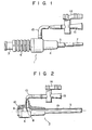
- Fig. 1 is a side view of an assembled catheter introducer device of the present invention;
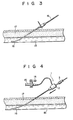
- Fig. 2 is a partial sectional view of the main body of the device shown in Fig. 1
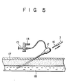
- Figs. 3, 4 and 5 are diagrams for explaining the operation for inserting the device shown in Fig. 1, 2 and 6 into a blood vessel; and
- Figs. 6 and 8 are perspective views showing another embodiment of a medical device of the present invention.
- The catheter introducer 1 (Fig. 1) of the present invention incldues a main body 2 (Fig. 2) and a
rod member 3. Themain body 2 corresponds to the sheath portion, and therod member 3 corresponds to the dilator portion of a catheter introducer. - The
main body 2 has ahub 4 and asheath 5 having its proximal portion fixed and supported by thehub 4, as shown in Fig. 2. Thehub 4 and thesheath 5 have a throughpath 19 for receiving atube 7 of therod member 3. - A
valve 8 is mounted, preferably, in the portion of the throughpath 19 in thehub 4. Thevalve 8 serves to prevent reverse flow of blood when the medical devicemain body 2 is inserted into a blood vessel. - The rod member or
dilator portion 3 has ahub 6 and atube 7 fixed and supported thereby. Thedilator portion 3 is inserted in and assembled with themain body 2 shown in Fig. 2. With this arrangement, when themain body 2 and therod member 3 are percutaneously inserted into a blood vessel, they rotate relative to each other and, as such, may not lend themselves to easy insertion, as described above. - In view of this problem, according to the present invention a mechanism for preventing relative rotation between the
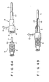
main body 2 and thedilator portion 3 is incorporated. - Figs. 6A and 6B show such an arrangement of a mechanism for preventing axial displacement and circumferential rotation.
- In the arrangement shown in Fig. 6A, fitting
portions rod member 3 and a medical devicemain body 2 have hexagonal sections to prevent relative rotations therebetween. Ribs 20 and 21 on thefitting portions ribs rib 20 slips over and positions beyond therib 21, thus preventing the axial movement. It is preferred to form three ribs, instead of theannular rib 20, on the periphery of theportion 11, spaced apart from each other at angular intervals of 120° when theportion 11 is of hexagonal shape. This configuration of the ribs facilitates the slipping-over and pulling-out operations. (Fig. 6B shows the state wherein thefitting portions reference numeral 22 denotes a shrinkage tube, and 23 a bending spring. - As described above, the sections of fitting portions of the
rod member 3 and the medical devicemain body 2 are non-circular but can be various shapes, including polygons such as hexagons or ellipses. - The method of using the medical device of the present invention will be described with reference to Figs. 3 to 5.
- A
guide wire 16 is inserted into ablood vessel 18 through asubcutaneous tissue 17 by a suitable method such as the Seldinger method (Fig. 5). Then, the medical device main body 1, obtained by assembling the sheath portion (medical device main body) 2 shown in Fig. 2 and the dilator portion (rod member) 3 shown in Fig. 4 so as to prevent axial movement and circumferential rotation as shown in Fig. 1, is inserted into ablood vessel 18 by inserting theguide wire 16 into thetube 7, thesheath 5 and the through hole in thehubs 4 and 6 (Fig. 6). - In this process, insertion into the blood vessel can be easily performed when the
hub 6 of thedilator portion 3 is rotated during insertion. In contrast, insertion of the main body 1 cannot be performed easily with a conventional device, since the conventional device does not include a mechanism for preventing relative rotation between the dilator and sheath portions, as described above. - In the medical device of the present invention, axial movement between the
portions blood vessel 18 through means of theguide wire 16 is facilitated. - Subsequently, the
sheath portion 6 is left in theblood vessel 18, and theguide wire 16 and thedilator portion 3 are pulled out (Fig. 5). - The catheter can be easily inserted into the
blood vessel 18 through the indwellingsheath portion 2. Since thesheath portion 2 has acheck valve 8, reverse flow of blood is prevented. If required, suction of a thrombus or injection of a physiological saline solution can be performed through thelure taper port 15 of thesheath portion 2 before or after insertion of the catheter. - When the resultant assembly is inserted into a blood vessel, as described with reference to Figs. 3 to 5, a suitable portion of the assembly, such as the hub of the rod member, is clamped such that the assembly is inserted while applying a rotational force around the guide wire. The insertion operation which, conventionally, has been complex is, through application of the invention, made easy.
Claims (4)
Applications Claiming Priority (2)
| Application Number | Priority Date | Filing Date | Title |
|---|---|---|---|
| JP165452/84 | 1984-08-07 | ||
| JP59165452A JPS6145774A (en) | 1984-08-07 | 1984-08-07 | Medical instrument |
Related Child Applications (4)
| Application Number | Title | Priority Date | Filing Date |
|---|---|---|---|
| EP89122017A Division EP0361548A3 (en) | 1984-08-07 | 1985-08-07 | Catheter introducer device |
| EP89122016A Division EP0365048A3 (en) | 1984-08-07 | 1985-08-07 | Catheter introducer device |
| EP89122017.0 Division-Into | 1989-11-29 | ||
| EP89122016.2 Division-Into | 1989-11-29 |
Publications (3)
| Publication Number | Publication Date |
|---|---|
| EP0171077A2 EP0171077A2 (en) | 1986-02-12 |
| EP0171077A3 EP0171077A3 (en) | 1987-02-04 |
| EP0171077B1 true EP0171077B1 (en) | 1990-11-14 |
Family
ID=15812686
Family Applications (2)
| Application Number | Title | Priority Date | Filing Date |
|---|---|---|---|
| EP85109936A Expired - Lifetime EP0171077B1 (en) | 1984-08-07 | 1985-08-07 | Catheter introducer device |
| EP89122016A Withdrawn EP0365048A3 (en) | 1984-08-07 | 1985-08-07 | Catheter introducer device |
Family Applications After (1)
| Application Number | Title | Priority Date | Filing Date |
|---|---|---|---|
| EP89122016A Withdrawn EP0365048A3 (en) | 1984-08-07 | 1985-08-07 | Catheter introducer device |
Country Status (4)
| Country | Link |
|---|---|
| US (1) | US4682981A (en) |
| EP (2) | EP0171077B1 (en) |
| JP (1) | JPS6145774A (en) |
| DE (1) | DE3580537D1 (en) |
Families Citing this family (92)
| Publication number | Priority date | Publication date | Assignee | Title |
|---|---|---|---|---|
| EP0269763B1 (en) * | 1986-10-09 | 1991-08-14 | Hakko Electric Machine Works Co. Ltd. | A set of double needles for injecting liquid medicine |
| US5026350A (en) * | 1986-10-09 | 1991-06-25 | Hakko Electric Machine Works Co., Ltd. | Set of double needles for injecting liquid medicine |
| US4790831A (en) * | 1987-03-30 | 1988-12-13 | Baxter Travenol Laboratories, Inc. | Torque-control catheter |
| JPH0446758Y2 (en) * | 1988-01-22 | 1992-11-04 | ||
| US4886507A (en) * | 1988-02-01 | 1989-12-12 | Medex, Inc. | Y connector for angioplasty procedure |
| US5149327A (en) * | 1989-09-05 | 1992-09-22 | Terumo Kabushiki Kaisha | Medical valve, catheter with valve, and catheter assembly |
| US5092846A (en) * | 1989-11-07 | 1992-03-03 | Sumitomo Bakelite Company Limited | Introducer for medical tube |
| US5098376A (en) * | 1989-12-22 | 1992-03-24 | Cardiopulmonics, Inc. | Apparatus and methods for furling and introducing an extrapulmonary blood gas exchange device |
| US5057084A (en) * | 1990-03-01 | 1991-10-15 | The Regents Of The University Of Michigan | Implantable infusion device |
| US5554117A (en) * | 1990-03-01 | 1996-09-10 | Michigan Transtech Corporation | Implantable access devices |
| US5226879A (en) * | 1990-03-01 | 1993-07-13 | William D. Ensminger | Implantable access device |
| US5356381A (en) * | 1990-03-01 | 1994-10-18 | Ensminger William D | Implantable access devices |
| US5352204A (en) * | 1990-03-01 | 1994-10-04 | Ensminger William D | Implantable access devices |
| US5263930A (en) * | 1990-03-01 | 1993-11-23 | William D. Ensminger | Implantable access devices |
| US5053013A (en) * | 1990-03-01 | 1991-10-01 | The Regents Of The University Of Michigan | Implantable infusion device |
| US5350360A (en) * | 1990-03-01 | 1994-09-27 | Michigan Transtech Corporation | Implantable access devices |
| US5180365A (en) * | 1990-03-01 | 1993-01-19 | Ensminger William D | Implantable infusion device |
| US5281199A (en) * | 1990-03-01 | 1994-01-25 | Michigan Transtech Corporation | Implantable access devices |
| US5163941A (en) * | 1991-05-07 | 1992-11-17 | California Medical Products | Intubation device |
| US5273546A (en) * | 1991-08-01 | 1993-12-28 | Medtronic, Inc. | Hemostasis valve |
| US5125903A (en) * | 1991-08-01 | 1992-06-30 | Medtronic, Inc. | Hemostasis valve |
| CA2127528C (en) * | 1992-01-07 | 2003-12-30 | Yosuke Okada | Catheter introducer |
| US5672158A (en) * | 1992-01-07 | 1997-09-30 | Sherwood Medical Company | Catheter introducer |
| FR2689402B1 (en) * | 1992-04-03 | 1997-07-04 | Farcot Jean Christian | PERCUTANE VASCULAR INTRODUCER FOR SUPPLYING AN EXTRACORPOREAL BLOOD CIRCUIT. |
| US5222951A (en) * | 1992-04-13 | 1993-06-29 | Leonard Bloom | Guarded skin hook for surgical use |
| DE4312147C2 (en) * | 1992-04-14 | 1996-01-25 | Olympus Optical Co | Trocar |
| CA2107852C (en) * | 1992-10-09 | 2004-09-07 | Gerald Leigh Metcalf | Trocar |
| US5391152A (en) * | 1993-03-12 | 1995-02-21 | C. R. Bard, Inc. | Catheter interlock assembly |
| JP2514845Y2 (en) * | 1993-05-25 | 1996-10-23 | 株式会社グッドマン | Catheter introducer |
| FR2707176A1 (en) * | 1993-07-08 | 1995-01-13 | Godillon Jean Francois | Device for puncture under reduced pressure, in particular for fitting a guide and/or a catheter in a cavity with liquid content in the body |
| US5421825A (en) * | 1993-10-06 | 1995-06-06 | Farcot; Jean-Christian | Percutaneous vascular introduction device for the feeding of an extracorporeal blood circuit |
| US5885217A (en) * | 1995-01-20 | 1999-03-23 | Tyco Group S.A.R.L. | Catheter introducer |
| US5680873A (en) * | 1995-03-02 | 1997-10-28 | Scimed Life Systems, Inc. | Braidless guide catheter |
| DE69601437T2 (en) | 1995-04-21 | 1999-09-30 | Bard Inc C R | Interlocking catheter unit |
| DE19515626C2 (en) * | 1995-04-28 | 2000-04-06 | Wolf Gmbh Richard | Instrument for positioning at least one working sleeve |
| US6273404B1 (en) * | 1995-06-05 | 2001-08-14 | Scimed Life Systems, Inc. | Method of making monolithic hub and strain relief |
| US5782807A (en) * | 1995-10-20 | 1998-07-21 | Tfx Medical Incorporated | Releasably locking introducer devices |
| US6451041B1 (en) | 1996-02-29 | 2002-09-17 | Stephen P. Moenning | Apparatus for protecting a port site opening in the wall of a body cavity and reducing electrosurgical injuries |
| US6379334B1 (en) * | 1997-02-10 | 2002-04-30 | Essex Technology, Inc. | Rotate advance catheterization system |
| CH692240A5 (en) * | 1997-03-26 | 2002-04-15 | Disetronic Licensing Ag | Catheter system for transdermal passage devices. |
| US5865817A (en) * | 1997-04-29 | 1999-02-02 | Moenning; Stephen P. | Apparatus and method for securing a medical instrument to a cannula of a trocar assembly |
| US5954643A (en) * | 1997-06-09 | 1999-09-21 | Minimid Inc. | Insertion set for a transcutaneous sensor |
| US6402207B1 (en) | 1997-06-09 | 2002-06-11 | Qd Enterprises, Llc | Safety indexed medical connectors |
| CA2310088C (en) | 1997-11-14 | 2008-12-16 | Carl E. Yee | Multi-sheath delivery catheter |
| US6949084B2 (en) * | 1998-05-14 | 2005-09-27 | Disetronic Licensing Ag | Catheter head for subcutaneous administration of an active substance |
| DE19821723C2 (en) | 1998-05-14 | 2000-07-06 | Disetronic Licensing Ag | Catheter head for subcutaneous administration of an active ingredient |
| AUPP550098A0 (en) * | 1998-08-26 | 1998-09-17 | Microcatheters Pty Ltd | Catheter guide |
| US6228073B1 (en) | 1998-12-15 | 2001-05-08 | Medtronic, Inc. | Angiography luer hub having wings proximal to the plurality of grips and strain relief |
| US6146372A (en) * | 1998-12-24 | 2000-11-14 | Datascope Investment Corp | Apparatus and method for the percutaneous insertion of a pediatric intra-aortic balloon catheter |
| DE19912434B4 (en) | 1999-03-19 | 2013-10-24 | Roche Diagnostics Gmbh | Infusion device, catheter device and catheter head |
| US20090093791A1 (en) * | 1999-09-17 | 2009-04-09 | Heuser Richard R | Devices and methods for treating chronic total occlusion |
| WO2001023027A1 (en) * | 1999-09-27 | 2001-04-05 | Essex Technology, Inc. | Rotate-to-advance catheterization system |
| US6613062B1 (en) * | 1999-10-29 | 2003-09-02 | Medtronic, Inc. | Method and apparatus for providing intra-pericardial access |
| US6336914B1 (en) | 2000-01-13 | 2002-01-08 | Gillespie, Iii Richard D. | Releasable interlock assembly having axial and rotational engagement |
| US6589262B1 (en) * | 2000-03-31 | 2003-07-08 | Medamicus, Inc. | Locking catheter introducing system |
| US7300459B2 (en) * | 2002-10-17 | 2007-11-27 | Heuser Richard R | Stent with covering and differential dilation |
| US7166088B2 (en) * | 2003-01-27 | 2007-01-23 | Heuser Richard R | Catheter introducer system |
| US7402141B2 (en) | 2003-08-27 | 2008-07-22 | Heuser Richard R | Catheter guidewire system using concentric wires |
| US7766898B2 (en) * | 2004-05-24 | 2010-08-03 | Merit Medical Systems, Inc. | Non-circular side port bore for introducer sheath |
| US20080154153A1 (en) * | 2004-08-25 | 2008-06-26 | Heuser Richard R | Multiple-wire systems and methods for ablation of occlusions within blood vessels |
| US8545418B2 (en) * | 2004-08-25 | 2013-10-01 | Richard R. Heuser | Systems and methods for ablation of occlusions within blood vessels |
| WO2006093976A1 (en) * | 2005-02-28 | 2006-09-08 | Spirus Medical Inc. | Rotate-to-advance catheterization system |
| US8235942B2 (en) | 2005-05-04 | 2012-08-07 | Olympus Endo Technology America Inc. | Rotate-to-advance catheterization system |
| US7780650B2 (en) * | 2005-05-04 | 2010-08-24 | Spirus Medical, Inc. | Rotate-to-advance catheterization system |
| US8343040B2 (en) | 2005-05-04 | 2013-01-01 | Olympus Endo Technology America Inc. | Rotate-to-advance catheterization system |
| US8317678B2 (en) | 2005-05-04 | 2012-11-27 | Olympus Endo Technology America Inc. | Rotate-to-advance catheterization system |
| US8414477B2 (en) | 2005-05-04 | 2013-04-09 | Olympus Endo Technology America Inc. | Rotate-to-advance catheterization system |
| JP4767655B2 (en) * | 2005-10-28 | 2011-09-07 | テルモ株式会社 | Protector and needle set |
| US7374567B2 (en) * | 2006-01-25 | 2008-05-20 | Heuser Richard R | Catheter system for connecting adjacent blood vessels |
| US20070203572A1 (en) * | 2006-01-25 | 2007-08-30 | Heuser Richard R | Catheter system with stent apparatus for connecting adjacent blood vessels |
| US20070203515A1 (en) * | 2006-01-25 | 2007-08-30 | Heuser Richard R | Catheter system for connecting adjacent blood vessels |
| US8062321B2 (en) * | 2006-01-25 | 2011-11-22 | Pq Bypass, Inc. | Catheter system for connecting adjacent blood vessels |
| US20070179454A1 (en) * | 2006-01-31 | 2007-08-02 | Smiths Medical Asd, Inc. | Safety needle assembly with correct medication connection |
| US8435229B2 (en) | 2006-02-28 | 2013-05-07 | Olympus Endo Technology America Inc. | Rotate-to-advance catheterization system |
| US8574220B2 (en) | 2006-02-28 | 2013-11-05 | Olympus Endo Technology America Inc. | Rotate-to-advance catheterization system |
| US7918783B2 (en) * | 2006-03-22 | 2011-04-05 | Boston Scientific Scimed, Inc. | Endoscope working channel with multiple functionality |
| US20080177249A1 (en) * | 2007-01-22 | 2008-07-24 | Heuser Richard R | Catheter introducer system |
| US20080234813A1 (en) * | 2007-03-20 | 2008-09-25 | Heuser Richard R | Percutaneous Interventional Cardiology System for Treating Valvular Disease |
| US8870755B2 (en) | 2007-05-18 | 2014-10-28 | Olympus Endo Technology America Inc. | Rotate-to-advance catheterization system |
| US9044266B2 (en) * | 2007-09-19 | 2015-06-02 | Cook Medical Technologies Llc | Implant deployment device |
| US20090192485A1 (en) * | 2008-01-28 | 2009-07-30 | Heuser Richard R | Snare device |
| US8114053B2 (en) * | 2008-07-17 | 2012-02-14 | Tyco Healthcare Group Lp | Port fixation with interlocking structure |
| US9364651B2 (en) | 2010-02-23 | 2016-06-14 | Smiths Medical Asd, Inc. | Adapter with special fitting |
| US20130158483A1 (en) * | 2011-03-01 | 2013-06-20 | Martin Senitko | Dialysis needle system |
| US8870238B2 (en) | 2011-06-27 | 2014-10-28 | Smiths Medical Asd, Inc. | Fitting for medicament infusion systems |
| US9220833B2 (en) | 2011-06-27 | 2015-12-29 | Smiths Medical Asd, Inc. | Medicament infusion systems |
| CN204485033U (en) * | 2012-03-27 | 2015-07-22 | 泰尔茂株式会社 | Guide |
| US10737087B2 (en) | 2012-04-17 | 2020-08-11 | Smiths Medical Asd, Inc. | Filling fitting |
| US10039912B2 (en) * | 2012-07-10 | 2018-08-07 | St. Jude Medical, Atrial Fibrillation Division, Inc. | System and method for coupling a tube with a medical device handle |
| USD741478S1 (en) * | 2014-01-17 | 2015-10-20 | Rocomp Global, Llc | Radiant energy and fluid guide |
| US10065029B2 (en) * | 2014-03-03 | 2018-09-04 | Cook Medical Technologies Llc | Mechanical dilator |
| US10569058B2 (en) | 2017-05-12 | 2020-02-25 | Ep Dynamics, Inc. | Introducer sheaths |
Family Cites Families (14)
| Publication number | Priority date | Publication date | Assignee | Title |
|---|---|---|---|---|
| US3399674A (en) * | 1965-07-01 | 1968-09-03 | Voys Inc Le | Catheter placement unit |
| US3633579A (en) * | 1967-05-24 | 1972-01-11 | Sherwood Medical Ind Inc | Catheter placement device and method |
| US3856009A (en) * | 1971-11-26 | 1974-12-24 | Johnson & Johnson | Catheter placement unit |
| US3788320A (en) * | 1972-02-25 | 1974-01-29 | Kendall & Co | Spinal needle |
| DE2305640C3 (en) * | 1973-02-06 | 1975-08-14 | B. Braun Melsungen Ag, 3508 Melsungen | Device for introducing flexible catheters |
| US4192306A (en) * | 1978-08-21 | 1980-03-11 | Abbott Laboratories | Catheter placement assembly having axial and rotational alignment means |
| US4300553A (en) * | 1978-10-12 | 1981-11-17 | Abbott Laboratories | Winged catheter placement assembly |
| US4496348A (en) * | 1979-11-29 | 1985-01-29 | Abbott Laboratories | Venipuncture device |
| CA1151862A (en) * | 1980-01-24 | 1983-08-16 | Thomas J. Fogarty | Flexible calibrator |
| FR2474317A1 (en) * | 1980-01-29 | 1981-07-31 | Technological Supply | Intravenous catheter probe of silicone tubing - reinforced during insertion by separate coaxial wire passing through leakproof membrane |
| JPS5743261A (en) * | 1980-08-28 | 1982-03-11 | Sharp Corp | Method for controlling input in cash register, etc. |
| DE3117802A1 (en) * | 1981-05-06 | 1982-11-25 | Max Dr. 8520 Erlangen Hubmann | CATHETER CUTLERY |
| JPS5889052U (en) * | 1981-12-10 | 1983-06-16 | テルモ株式会社 | intravascular indwelling needle |
| US4445893A (en) * | 1982-05-13 | 1984-05-01 | Sherwood Medical Company | Infusion apparatus |
-
1984
- 1984-08-07 JP JP59165452A patent/JPS6145774A/en active Granted
-
1985
- 1985-08-05 US US06/762,613 patent/US4682981A/en not_active Expired - Lifetime
- 1985-08-07 DE DE8585109936T patent/DE3580537D1/en not_active Expired - Lifetime
- 1985-08-07 EP EP85109936A patent/EP0171077B1/en not_active Expired - Lifetime
- 1985-08-07 EP EP89122016A patent/EP0365048A3/en not_active Withdrawn
Also Published As
| Publication number | Publication date |
|---|---|
| EP0171077A2 (en) | 1986-02-12 |
| DE3580537D1 (en) | 1990-12-20 |
| JPH0337430B2 (en) | 1991-06-05 |
| JPS6145774A (en) | 1986-03-05 |
| US4682981A (en) | 1987-07-28 |
| EP0365048A2 (en) | 1990-04-25 |
| EP0365048A3 (en) | 1990-06-13 |
| EP0171077A3 (en) | 1987-02-04 |
Similar Documents
| Publication | Publication Date | Title |
|---|---|---|
| EP0171077B1 (en) | Catheter introducer device | |
| EP0001106B1 (en) | Catheter assembly | |
| US5971958A (en) | Interlocking catheter assembly | |
| US4676530A (en) | Coupling assembly for use in fluid flow systems | |
| CA1085252A (en) | Connector for attachment of blood tubing to external arteriovenous shunts and fistulas | |
| US4973313A (en) | Over the needle catheter introducer | |
| US6159198A (en) | Introducer system | |
| US5125915A (en) | Locking y-connector for selective attachment to exterior of medical tubing | |
| US4387879A (en) | Self-sealing connector for use with plastic cannulas and vessel catheters | |
| AU613234B2 (en) | Femoral arterial cannula | |
| EP0862471B1 (en) | Releasably locking introducer devices | |
| EP0553254B1 (en) | Catheter attachment device | |
| EP0522735B1 (en) | Locking dilator for peel away introducer sheath | |
| US5674201A (en) | Rotatable catheter housed within a flexible wing assembly | |
| US5707363A (en) | Guidewire retention device | |
| EP0566426A1 (en) | Rotating Y-connector | |
| EP0732120A1 (en) | Control forward/flashback forward one hand introducer needle and catheter assembly | |
| GB1578152A (en) | Catheter | |
| EP0850658B1 (en) | A needle and valve assembly for use with a catheter | |
| JPS6122989B2 (en) | ||
| JPH05115559A (en) | Compression gasket for y-connector | |
| WO1998013083A1 (en) | Catheter sheath introducer with improved hemostasis valve | |
| EP0442194A2 (en) | Cylindrical plug for sealing around guidewire | |
| EP0680356B1 (en) | Catheter introducer | |
| JPS588251B2 (en) | Intravenous catheter assembly |
Legal Events
| Date | Code | Title | Description |
|---|---|---|---|
| PUAI | Public reference made under article 153(3) epc to a published international application that has entered the european phase |
Free format text: ORIGINAL CODE: 0009012 |
|
| 17P | Request for examination filed |
Effective date: 19850904 |
|
| AK | Designated contracting states |
Designated state(s): BE DE FR GB IT SE |
|
| PUAL | Search report despatched |
Free format text: ORIGINAL CODE: 0009013 |
|
| AK | Designated contracting states |
Kind code of ref document: A3 Designated state(s): BE DE FR GB IT SE |
|
| 17Q | First examination report despatched |
Effective date: 19880323 |
|
| GRAA | (expected) grant |
Free format text: ORIGINAL CODE: 0009210 |
|
| ITF | It: translation for a ep patent filed |
Owner name: FUMERO BREVETTI S.N.C. |
|
| AK | Designated contracting states |
Kind code of ref document: B1 Designated state(s): BE DE FR GB IT SE |
|
| XX | Miscellaneous (additional remarks) |
Free format text: TEILANMELDUNG 89122016.2 EINGEREICHT AM 07/08/85. |
|
| ET | Fr: translation filed | ||
| REF | Corresponds to: |
Ref document number: 3580537 Country of ref document: DE Date of ref document: 19901220 |
|
| ITTA | It: last paid annual fee | ||
| PLBE | No opposition filed within time limit |
Free format text: ORIGINAL CODE: 0009261 |
|
| STAA | Information on the status of an ep patent application or granted ep patent |
Free format text: STATUS: NO OPPOSITION FILED WITHIN TIME LIMIT |
|
| 26N | No opposition filed | ||
| EAL | Se: european patent in force in sweden |
Ref document number: 85109936.6 |
|
| REG | Reference to a national code |
Ref country code: GB Ref legal event code: IF02 |
|
| PGFP | Annual fee paid to national office [announced via postgrant information from national office to epo] |
Ref country code: GB Payment date: 20040804 Year of fee payment: 20 |
|
| PGFP | Annual fee paid to national office [announced via postgrant information from national office to epo] |
Ref country code: SE Payment date: 20040806 Year of fee payment: 20 |
|
| PGFP | Annual fee paid to national office [announced via postgrant information from national office to epo] |
Ref country code: FR Payment date: 20040810 Year of fee payment: 20 |
|
| PGFP | Annual fee paid to national office [announced via postgrant information from national office to epo] |
Ref country code: DE Payment date: 20040819 Year of fee payment: 20 |
|
| PGFP | Annual fee paid to national office [announced via postgrant information from national office to epo] |
Ref country code: BE Payment date: 20041020 Year of fee payment: 20 |
|
| PG25 | Lapsed in a contracting state [announced via postgrant information from national office to epo] |
Ref country code: GB Free format text: LAPSE BECAUSE OF EXPIRATION OF PROTECTION Effective date: 20050806 |
|
| BE20 | Be: patent expired |
Owner name: *TERUMO K.K. TRADING AS TERUMO CORP. Effective date: 20050807 |
|
| REG | Reference to a national code |
Ref country code: GB Ref legal event code: PE20 |
|
| EUG | Se: european patent has lapsed | ||
| BE20 | Be: patent expired |
Owner name: *TERUMO K.K. TRADING AS TERUMO CORP. Effective date: 20050807 |