EP0171975B1 - Improved methods and apparatus for embossing a precision optical pattern in a resinous sheet or laminate - Google Patents
Improved methods and apparatus for embossing a precision optical pattern in a resinous sheet or laminate Download PDFInfo
- Publication number
- EP0171975B1 EP0171975B1 EP85305462A EP85305462A EP0171975B1 EP 0171975 B1 EP0171975 B1 EP 0171975B1 EP 85305462 A EP85305462 A EP 85305462A EP 85305462 A EP85305462 A EP 85305462A EP 0171975 B1 EP0171975 B1 EP 0171975B1
- Authority
- EP
- European Patent Office
- Prior art keywords
- sheeting
- embossing
- film
- temperature
- pattern
- Prior art date
- Legal status (The legal status is an assumption and is not a legal conclusion. Google has not performed a legal analysis and makes no representation as to the accuracy of the status listed.)
- Expired - Lifetime
Links
Images
Classifications
-
- B—PERFORMING OPERATIONS; TRANSPORTING
- B29—WORKING OF PLASTICS; WORKING OF SUBSTANCES IN A PLASTIC STATE IN GENERAL
- B29C—SHAPING OR JOINING OF PLASTICS; SHAPING OF MATERIAL IN A PLASTIC STATE, NOT OTHERWISE PROVIDED FOR; AFTER-TREATMENT OF THE SHAPED PRODUCTS, e.g. REPAIRING
- B29C59/00—Surface shaping of articles, e.g. embossing; Apparatus therefor
-
- B—PERFORMING OPERATIONS; TRANSPORTING
- B29—WORKING OF PLASTICS; WORKING OF SUBSTANCES IN A PLASTIC STATE IN GENERAL
- B29D—PRODUCING PARTICULAR ARTICLES FROM PLASTICS OR FROM SUBSTANCES IN A PLASTIC STATE
- B29D11/00—Producing optical elements, e.g. lenses or prisms
- B29D11/00009—Production of simple or compound lenses
- B29D11/00278—Lenticular sheets
-
- B—PERFORMING OPERATIONS; TRANSPORTING
- B29—WORKING OF PLASTICS; WORKING OF SUBSTANCES IN A PLASTIC STATE IN GENERAL
- B29C—SHAPING OR JOINING OF PLASTICS; SHAPING OF MATERIAL IN A PLASTIC STATE, NOT OTHERWISE PROVIDED FOR; AFTER-TREATMENT OF THE SHAPED PRODUCTS, e.g. REPAIRING
- B29C59/00—Surface shaping of articles, e.g. embossing; Apparatus therefor
- B29C59/02—Surface shaping of articles, e.g. embossing; Apparatus therefor by mechanical means, e.g. pressing
- B29C59/022—Surface shaping of articles, e.g. embossing; Apparatus therefor by mechanical means, e.g. pressing characterised by the disposition or the configuration, e.g. dimensions, of the embossments or the shaping tools therefor
-
- B—PERFORMING OPERATIONS; TRANSPORTING
- B29—WORKING OF PLASTICS; WORKING OF SUBSTANCES IN A PLASTIC STATE IN GENERAL
- B29C—SHAPING OR JOINING OF PLASTICS; SHAPING OF MATERIAL IN A PLASTIC STATE, NOT OTHERWISE PROVIDED FOR; AFTER-TREATMENT OF THE SHAPED PRODUCTS, e.g. REPAIRING
- B29C59/00—Surface shaping of articles, e.g. embossing; Apparatus therefor
- B29C59/02—Surface shaping of articles, e.g. embossing; Apparatus therefor by mechanical means, e.g. pressing
- B29C59/04—Surface shaping of articles, e.g. embossing; Apparatus therefor by mechanical means, e.g. pressing using rollers or endless belts
- B29C59/046—Surface shaping of articles, e.g. embossing; Apparatus therefor by mechanical means, e.g. pressing using rollers or endless belts for layered or coated substantially flat surfaces
-
- B—PERFORMING OPERATIONS; TRANSPORTING
- B29—WORKING OF PLASTICS; WORKING OF SUBSTANCES IN A PLASTIC STATE IN GENERAL
- B29D—PRODUCING PARTICULAR ARTICLES FROM PLASTICS OR FROM SUBSTANCES IN A PLASTIC STATE
- B29D11/00—Producing optical elements, e.g. lenses or prisms
-
- B—PERFORMING OPERATIONS; TRANSPORTING
- B29—WORKING OF PLASTICS; WORKING OF SUBSTANCES IN A PLASTIC STATE IN GENERAL
- B29D—PRODUCING PARTICULAR ARTICLES FROM PLASTICS OR FROM SUBSTANCES IN A PLASTIC STATE
- B29D11/00—Producing optical elements, e.g. lenses or prisms
- B29D11/00009—Production of simple or compound lenses
-
- B—PERFORMING OPERATIONS; TRANSPORTING
- B29—WORKING OF PLASTICS; WORKING OF SUBSTANCES IN A PLASTIC STATE IN GENERAL
- B29D—PRODUCING PARTICULAR ARTICLES FROM PLASTICS OR FROM SUBSTANCES IN A PLASTIC STATE
- B29D11/00—Producing optical elements, e.g. lenses or prisms
- B29D11/00605—Production of reflex reflectors
-
- B—PERFORMING OPERATIONS; TRANSPORTING
- B32—LAYERED PRODUCTS
- B32B—LAYERED PRODUCTS, i.e. PRODUCTS BUILT-UP OF STRATA OF FLAT OR NON-FLAT, e.g. CELLULAR OR HONEYCOMB, FORM
- B32B38/00—Ancillary operations in connection with laminating processes
- B32B38/06—Embossing
-
- G—PHYSICS
- G02—OPTICS
- G02B—OPTICAL ELEMENTS, SYSTEMS OR APPARATUS
- G02B5/00—Optical elements other than lenses
- G02B5/12—Reflex reflectors
- G02B5/122—Reflex reflectors cube corner, trihedral or triple reflector type
- G02B5/124—Reflex reflectors cube corner, trihedral or triple reflector type plural reflecting elements forming part of a unitary plate or sheet
-
- B—PERFORMING OPERATIONS; TRANSPORTING
- B29—WORKING OF PLASTICS; WORKING OF SUBSTANCES IN A PLASTIC STATE IN GENERAL
- B29L—INDEXING SCHEME ASSOCIATED WITH SUBCLASS B29C, RELATING TO PARTICULAR ARTICLES
- B29L2011/00—Optical elements, e.g. lenses, prisms
- B29L2011/0083—Reflectors
-
- B—PERFORMING OPERATIONS; TRANSPORTING
- B32—LAYERED PRODUCTS
- B32B—LAYERED PRODUCTS, i.e. PRODUCTS BUILT-UP OF STRATA OF FLAT OR NON-FLAT, e.g. CELLULAR OR HONEYCOMB, FORM
- B32B2307/00—Properties of the layers or laminate
- B32B2307/40—Properties of the layers or laminate having particular optical properties
- B32B2307/416—Reflective
Description
- This invention relates to improved methods and apparatusfor producing sheeting having precision patterns where flatness and angular accuracy are important, such as for optical purposes, such as Fresnel lenses incorporating catadioptrics, precise flats, angles and uniform detail, and, more particularly, to improved methods and apparatus for continuously embossing a repeating retroreflecting pattern of fine or precise detail on one surface of sheeting of transparent thermoplastic material or a laminate of such materials to form the sheeting into the desired pattern. Specifically, the techniques are applicable to produce cube-corner type retroreflective sheeting.
- Cube-corner type reflectors have been known for many years and many millions have been sold. The phrase "cube-corner" or "trihedral", or "tetrahedron" are art recognized terms for structure consisting of three mutually perpendicular faces, without regard to the size or shape of each face, or the optical axis of the element so provided. Each of the faces can assume a different size and shape relative to the other two, depending upon the angular reflective characteristics desired, and the molding techniques employed. One example of a cube-corner type reflector is provided by Stimson U.S. Patent No. 1,906,655, issued May 2, 1933, wherein there is disclosed a reflex light reflector including an obverse face and a reverse light reflecting face consisting of a plurality of cube-corner reflector elements, each having three mutually perpendicular surfaces adapted for total internal reflection of light impinging thereon from the obverse face. Reflectors, as taught by the Stimson patent, are individually molded and are relatively quite thick and rigid. For many years now, the preferred material for cube-corner type reflectors has been methyl methacrylate. Another example of a cube-corner type reflector is the rectangular parallelepiped disclosed in Healey U.S. Patent No. 4,073,568.
- It long has been desired to obtain the benefits of cube-corner reflectors as used in pavement markers or for automotive purposes, but with the reflector in the form of flexible sheeting. This involves, among other things, a drastic reduction in the size of the cube-corner elements.
- Cube-corner type reflectors, to retain their functionality of reflecting light back generally to its source, require that the three reflective faces be maintained flat and within several minutes of 90° relative to each other; spreads beyond this, or unevenness in the faces, results in significant light spread and a drop in intensity at the location desired.
- Prior attempts have been made to produce reflective sheeting wherein the reflective elements are of the cube-corner type. For many years, it was suggested that cube-corner sheeting could not be manufactured using embossing techniques (e.g. Rowland U.S. Patent No. 3,684,348, Col. 5 ii. 30-42).
- A more recent attempt at embossing cube-corner sheeting is that of Rowland U.S. Patent No. 4,244,683, issued January 13, 1981. However, the method and apparatus of Rowland U.S. Patent No. 4,244,683 are relatively quite complex and only semi-continuous or sequential in nature. Consequently, the Rowland teaching is quite costly to implement, maintain and operate. The operation is slow and the resultant reflective sheeting is quite costly. Moreover, to produce
sheeting 48 inches wide, to be economically feasible, would be prohibitively expensive and complicated using the sequential mold technique of Rowland 4,244,683. - Also known are other prior techniques for embossing repeating patterns on thermoplastic sheeting, among which other prior techniques are those taught by the following:
- Swallow U.S. Patent No. 2,442,443, issued June 1, 1948;
- Hochberg U.S. Patent No. 3,157,723, issued November 17, 1964;
- Kloender U.S. Patent No. 3,246,365, issued April 19, 1966;
- Bergh U.S. Patent No. 4,097,634, issued June 27, 1978; and
- Nyfeler et al. U.S. Patent No. 4,223,050, issued September 16, 1980.
- These other prior techniques do not involve the production of retro-reflective sheeting orthe precision patterns required for optical purposes. As noted, in order for cube-corner reflective sheeting to be successful, the embossed cube-corner elements must be extremely accurately formed, much more so than is required of the embossed elements of these "other prior techniques", which, therefore, although they may be satisfactory for producing the intended products, may not be adaptable to the production of cube-corner reflective sheeting.
- In Patent No. 4,486,363 there is disclosed a novel method and apparatus for continuously embossing a precision optical pattern on one surface of a continuous resinous sheeting material. The present invention discloses and claims improved methods and apparatus capable of producing embossed cube-cornertype sheeting having significantly higher degrees of reflective efficiency.
- Accordingly, an important object of the present invention is to provide improved methods and apparatus for embossing a repeating retroreflective. pattern of cube-corner reflecting elements on one face of sheeting of transparent thermoplastic material, or a laminate of such materials, which methods and apparatus operate continuously and are greatly simplified with respect to the prior art.
- Another important object is to provide such improved methods and apparatus which are relatively inexpensive, in terms of implementation and operation, yet when used in conjunction with the inventions disclosed and claimed in applicants' 4,486,363, operate to provide significant increases in reflectivity in the final embossed products.
- A further important object is to provide such improved methods and apparatus enabling continuous production of cube-corner reflective sheeting of reduced cost.
- The foregoing and other objects and advantages will appear from the following description of examples of the invention.
- According to the invention, there is provided a method for continuously embossing a precision optical pattern requiring sharp angles and flatness of faces in certain detail on one surface of a continuous resinous sheeting material, the method being performed with the aid of a generally cylindrical endless metal embossing element having an inner surface and an outer surface, the outer surface having a precision optical embossing pattern which is the reverse of the precision optical pattern to be formed on one surface of said sheeting, and wherein the method includes the steps of:
- (a) continuously moving the endless embossing element along a closed course through a heating station, where said embossing element is heated through its inner surface to a predetermined temperature and then to a cooling station where said embossing element is cooled below said predetermined temperature;
- (b) continuously feeding onto said embossing element as it passes through a part of said heating station superimposed resinous film and sheeting materials, said resinous materials of said film and said sheeting each having different glass transition temperatures, said sheeting being in direct contact with the outer precision patterned surface of said embossing tool;
- (c) continuously heating said embossing element to said predetermined temperature at said heating station, said temperature being greater than the glass transition temperature of said sheeting and less than the glass transition temperature of said resinous film;
- (d) pressing said superimposed film and sheeting against said embossing element at a plurality of pressure points sequentially spaced along said heating station with one surface of said sheeting confronting and engaging said precision optical pattern on said embossing element until said one surface of said sheeting conforms to said precision optical embossing pattern;
- (e) continuously passing said embossing element and said superimposed film and sheeting through said cooling station where the temperature of said embossing element and said sheeting is lowered below said sheeting glass transition temperature, with said film serving to substantially continuously maintain said sheeting in engagement with said embossing element through the heating station and through said cooling station; and
- (f) continuously stripping said superimposed layer of film and embossed sheeting from said embossing element, said film being later strippable from the other face of said sheeting without destroying said optical pattern formed on said one face of said sheeting, characterised in that:
- (g) said cooling step is substantially effected while said superimposed film and sheeting and embossing tool are disposed in a generally planar condition, thereby to achieve an increase in the optical efficiency of the embossed sheeting.
- The invention further provides apparatus for continuously embossing a precision optical pattern on one surface of transparent resinous material or materials, said apparatus comprising:
- (a) embossing means including a continuous seamless embossing tool in the form of a thin metal element having an inner surface and an outer surface, said outer surface having a precision optical embossing pattern thereon which is the reverse of the precision optical pattern to be formed in the resinous material;
- (b) means for continuously moving said embossing element along a closed course;
- (c) means for introducing superimposed film and sheeting of resinous materials onto said embossing element with one face of said sheeting in direct contact with said optical pattern on said embossing element;
- (d) heating means for raising the temperature of said embossing pattern to be above the glass transition temperature of said sheeting and below the glass transition temperature of said film while said embossing element is in a first portion of its course;
- (e) cooling means for lowering the temperature of said sheeting to be below said glass transition temperature;
- (f) a plurality of pressure means sequentially spaced along said first portion of said course for pressing said superimposed film and sheeting against said embossing element with said one surface of said sheeting confronting and engaging said embossing pattern until said one surface conforms to said embossing pattern, with said film serving to substantially continuously maintain said sheeting in engagement with said embossing element until the latter passes said second portion of said course;
- (g) means for thereafter stripping said superimposed film and sheeting from said embossing element; characterised in that:-
said cooling means lowers the temperature of said sheeting to be below said glass transition temperature while said element and said sheeting are in a generally planar condition in their course, thereby to rigidify said precision pattern while in an undistorted condition. - In a preferred embodiment, the sheeting is reheated to an annealing temperature where internal stresses caused by embossing and cooling are relieved, while preserving and enhancing the reflective efficiency of the precision optical pattern so formed.
- A preferred material for the sheeting is acrylic. The embossing tool preferably is a continuous belt, having the embossing pattern on its outer surface. The heating station is provided by a roller, and the cooling station may comprise a manifold that directs a cooled fluid (liquid or gas) against the embossed sheeting material while the belt and the formed material are in a generally planar condition. The post-cooling annealing step is best accomplished after the embossed thermoplastic material is stripped from the embossing tool and while the embossed material is still under moderate tension.
- As disclosed in US Patent No. 4,486,363 and UK Application No. 2127344A the sheeting, prior to engaging the embossing tool, is engaged on its surface remote from the one surface, with a film of thermoplastic material, such as polyester (Mylar), having a glass transition temperature which is higher than that of the sheeting and higher than the temperature of the embossing pattern at the heating station, so that the pressure points exert pressure on the sheeting through the film to cause the one surface of the sheeting to conform to the embossing pattern. The film acts as a carrier for the sheeting in its weak, molten condition and during and after cooling and annealing and keeps the sheeting from tearing. The film also acts as an interleaf between the sheeting and the pressure points, which preferably are pressure rollers of silicone rubber with a durometer hardness from Shore A 60 to 90, which would otherwise tend to stick to the sheeting.
- The invention will be described with reference to the accompanying drawings, in which:
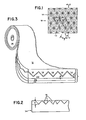
- Fig. 1 is a plan view, greatly enlarged and somewhat fragmentary, of the embossed surface of one form of reflective sheeting produced by the present invention;
- Fig. 2 is a side elevation, somewhat fragmentary and somewhat schematic and very enlarged view, showing the embossing pattern of one form of an embossing tool for embossing the retroreflecting pattern of the sheeting of Fig. 1, as though taken in the direction of the arrows 2-2 in Fig. 1, except that the tool is of female cubes and the sheeting of male cubes;
- Fig. 3 is a perspective, somewhat schematic view of one form of reflective sheeting produced by the present invention, after further processing has rendered the sheeting ready for installation; and
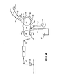
- Fig. 4 is a schematic representation of preferred apparatus constructed in accordance with the invention for producing the reflective sheeting of Figs. 1, and 3, the machine including embossing means comprising an embossing tool in the form of a continuous flexible cylinder, or belt, cooling means, and annealing means.
- Fig. 1 shows in plan view the rear surface of a portion of flexible
reflective sheeting 12 of transparent thermoplastic material having embossed on one surface thereof a repeating retroreflecting pattern of cube-cornertype reflector elements 14. The thermoplastic material may advantageously be acrylic.Sheeting 12 initially had parallel front and back surfaces and was initially on the order of 0.1524 mm thick. Alternatively, thesheeting 12 may consist of a laminate of different transparent thermoplastic materials having different characteristics, as hereinafter discussed. - The retroreflective pattern of
elements 14 was formed with the aid of an embossing tool of a thin flexible belt or cylinder of the type produced in accordance with that invention entitled Embossing Tool and Method of Producing Same, U.S. Application Serial No. 06/430,866, filed September 30, 1982, now Patent No. 4,478,769, and assigned to applicants' assignee and UK Application No. 2127344A. As shown in Fig. 2, the embossing tool has on one surface anembossing pattern 16, the depth which is indicated by dimension A. One example for dimension A may be 0-0859 mm. Dimension B on Fig. 1, represents the distance between parallel grooves which, for the "A" dimension provided, would be about 0.183 mm. - In order for sheeting 12 to have adequate optical properties, the
embossing pattern 16 must be extremely accurately formed and the retroreflective pattern of the cube-corner elements 14 must be an extremely accurate reverse reproduction of theembossing pattern 16. Thus, the embossed surface of thesheeting 12 must conform to theembossing pattern 16 with an extremely high degree of accuracy. - Fig. 3 shows one form of
sheeting 12 produced by the present invention, after further processing and ready for use. More specifically, the retroreflective pattern of cube-corner elements 14 may be covered with a metallizedlayer 18, which in turn may be covered by a suitable adhesive 22 (for mounting), in turn covered by release paper 24. The thickness of themetallizing layer 18 is immeasurable. Backingmaterial 20 may have a thickness, dimension C, of about 0.0254 mm and the thickness of adhesive 22 may be about 0.0381 mm. The total thickness of thecomplete structure 25 is about 0.254 mm, and it is flexible enough so it can be rolled and readily stored on asupply reel 26. Thesheeting 12 may be any desired color, to impart that color to retroreflected light. The details of applying a back coat and adhesive are well known in the art and similar to that used in the manufacture of "glass bead" type sheeting. In lieu of metallizing, other materials and/or back coatings may be applied to the cube-corner elements, such post forming steps not forming part of the present invention. - A preferred machine 28 for producing the cube-
corner sheeting 12 is shown schematically in elevation in Fig. 4. It will be understood that the specific constructional details of the basic embossing machine 28 are substantially as disclosed in U.S. Patent No. 4,486,363 and U.K. Application No. 2127344A, and for purposes of convenience, a like numbering system for major components of such system is adopted herein. - A
supply reel 36 of unprocessedacrylic web 13 is mounted on the righthand end of the machine, as is a supply reel 40 of transparent plastic film such asMylar film 42. In the illustrated embodiment, theweb 13 may be 0.1524 mm thick and thefilm 42 may be 0.0508 mm thick. Theflat web 13 and thefilm 42 are fed fromreels 36 and 40, respectively, to the embossing means 34, over guide rollers (not shown), in the direction of the arrows. - The embossing means 34 includes an embossing tool 46 in the form of an
endless metal belt 48 which may be about 0.508 mm in thickness and 54 inches in "circumference" and 22 inches wide. The width and circumference of thebelt 48 will depend, in part, upon the width or material to be embossed and the desired embossing speed and the thickness of thebelt 48.Belt 48 is mounted on and carried by aheating roller 50 and apost-cooling roller 52 having parallel axes.Rollers belt 48 at a predetermined linear speed in the direction of the arrow.Belt 48 is provided on its outer surface with a continuous female embossing pattern 16 (Fig. 2). - Evenly spaced sequentially around the belt, for about 82°C around the
heating roller 50, are a plurality, at least three, and as shown five,pressure rollers 58 of a resilient material, preferably silicone rubber, with a durometer hardness ranging fromShort A 20 to 90, but preferably, from Shore A 60 to 90. - While
rollers heating roller 50 is about 26.67 cm and the diameter ofpost cooling roller 52 is about 20.32 cm. The diameter of eachroller 58 is about 15.24 cm. For purposes of illustration, the spacing betweenrollers rollers belt 48. It will be understood that the gap or free area between the rollers will differ depending upon the selected dimensions of thetool 48 androllers - It should be understood that either the
heating roller 50 or thepost-cooling roller 52, may have axial inlet and outlet passages joined by an internal spiral tube for circulation therethrough of hot oil (in the case of heating roller 50) supplied through a supply line or other material (in the case of cooling roller 52) also supplied through appropriate lines. - The
web 13 and thefilm 42, as stated, are fed to embossing means 34, where they are superimposed to form a laminate 69 which is introduced between thebelt 48 and the leading pressure roller 58a, with theweb 13 between thefilm 42 and thebelt 48. One face ofweb 13 directly confronts and engagesembossing pattern 16 and one face of thefilm 42 directly confronts and engagespressure rollers 58. The laminate 69 is moved with thebelt 48 to pass under the remainingpressure rollers 58 and around theheating roller 50 and from thence alongbelt 48 through a generalplanar cooling station 80 located betweenheating roller 50 andpost-cooling roller 52. - The
film 42 performs several functions during this operation. First, it serves to maintain theweb 13 under pressure against thebelt 48 while travelling around the heating andpost-cooling rollers web 13 with theprecision pattern 16 of the tool during the change in temperature gradient as the web (now embossed sheet) drops below the glass transition temperature of the material. Second, the film maintains what will be the outer surface of the sheeting in a flat and highly finished surface for optical transmission. Finally, thefilm 42 acts as a carrier for the web in its weak "molten" state and prevents the web from otherwise adhering to thepressure rollers 58 as the web is heated above the glass transition temperature. - The embossing means 34 includes a
stripper roller 70, around which laminate 69 is passed to remove the same from thebelt 48, shortly before thebelt 48 itself contactspost-cooling roller 52 on its return path to theheating roller 50. - The laminate 69 is then fed from
stripper roller 70 over further guidingrollers 44, to an annealing means 90. The laminate 69 then emerges from the annealing means 90, guided by additional guidingrollers 44, with thefilm 42 facing outwardly, past amonitoring device 74 for continuously monitoring the optical performance of the embossed reflective sheeting. From there, thefinished laminate 69 having the embossedsheeting 13, may be transferred to a wind-up roller (not shown) for removal and further processing. - The
heating roller 50 is internally heated (as aforesaid) so that asbelt 48 passes thereover through the heating station, the temperature of theembossing pattern 16 at the portion of the tool is raised sufficiently so thatweb 13 is heated to a temperature above its glass transition temperature, but not sufficiently high as to exceed the glass transition temperature offilm 42. For the acrylic web (or sheeting) 13 andpolyester film 42, a suitable temperature forheating roller 50 in the heating station is in the range from 218°C to 246°C, and preferably about 218°C. - The
post-cooling roller 52 also may be internally heated (as aforesaid) so that asbelt 48 passes thereover through the cooling station, the temperature of the portion of thetool embossing pattern 16 is maintained at about the same temperature to which thebelt 48 is lowered at thecooling station 80. - As previously noted, the present invention provided significant and unexpected improvements in the reflective efficiency of the sheeting produced thereby.
- The first such improvement is achieved by causing the embossed
laminate 69 andtool 48 to be abruptly and significantly cooled while thetool 48 andlaminate 69 are in a generally planar position. Applicants have discovered that by promptly effecting such cooling in the "flat", a three-fold increase in specific intensity of the sheeting can be achieved, as compared to cooling around theroller 52. - In order to effect such prompt and full cooling, the cooling station designated generally 80 is provided on the embossing apparatus 28. The cooling station may consist of a simple shroud of
manifold 81 closely spaced to the outer face of thecarrier film 42 at the area located between therollers belt 48 is under tension and planar, and with theweb 42 holding the formedsheeting 13 thereagainst. A suitable source forchilled fluid 83 and appropriate inlet andoutlet ductwork pump 86 for circulation of the chilled fluid also are provided. The chilled fluid may be water, air, or, for example, other gases or fluids such as liquid nitrogen. Satisfactory results have been achieved when the chilled fluid is on the order of about 10°C so as to cause the laminate 69 and thetool 48 to quickly drop below 82°C in temperature, and preferably cooled to a range of approximately 38°C to 49°C. This rapid cooling below the glass transition temperature of thesheeting 13, while the formedcubes 14 andfilm carrier 42 are in a generally flat and undistorted condition, apparently effectively rigidifies or "freezes" the precision formed cube-corner elements 14 of thesheeting 13. Because thetool 48 is extremely thin, it is desirable to maintain its temperature at about 49°C as it passes over thepost-cooling roller 52 and back toward theheating roller 50. - As previously noted, the space between
rollers rollers - A second important and unexpected improvement in reflective efficiency is provided by subsequently rating the formed film to a relatively high temperature, in the range of 82°C to 93°C, after the
sheeting 13 andfilm 42 is cooled and stripped from theembossing tool 58. It has been found that this reheating, in the range indicated, generally provides an additional 25% or more increase in the reflective efficiency in sheeting which is cooled in the "flat", and an even greater percentage increase for sheeting which is simply cooled by passing it over thepost-cooling roller 52. While the particular phenomenon is not understood, it is believed that it is similar to an annealing process, wherein any stresses which are "frozen" into the film during the cooling stage are relieved, so that the cube-corner elements can relax to a condition very highly approximating the precision angles formed during the embossing stage. For purposes of this application therefor, this reheating step also may be referred to as annealing. The annealing step can be accomplished by running the material directly through the annealing or reheatingoven 90, positioned directly near theembossing mechanism 20, so that annealing can be done in a continuous fashion. For example, the material may run through at a rate of 1.2 meters per minute, and the sheeting material would be subject to the annealing temperatures for at least ten minutes. Where continuous annealing is performed, it is desirable that there be some tension on the laminate 69, but it should be a very low tension which would be approximately less than 0.0893 kgms of tension per cm of width of laminate. - It also has been found that it is desirable to run the material through the annealing oven while the
Mylar carrier film 42 still is associated with the formed sheeting, and that a lower reflective efficiency improvement is accomplished if performed without thefilm 42. - Alternatively, the finished roll of film with the Mylar thereon can be subjected to a static heating technique, where the entire roll is placed in an oven and allowed to be heated for an extended time period, until the entire roll reaches the designated temperature range. No set time can be provided since it will depend upon the size of the roll.
- It has been found that if reheating occurs below 82°C, there apparently is insufficient "relief" of the cube-corner elements, and that if reheated above 93°C, there is a rather rapid drop in the reflective capability of the cube-corner elements, presumably because the material then loses its critical shape. It has been found that 91°C is the optimum temperature for providing significant stability in the annealed cube-corner elements, while preserving the greatest degree of improved reflectivity. The concept of, and result of, the annealing step is unexpected. It has heretofore been believed that any reheating of any acrylic material used in forming cube-corner reflectors, where injection molded or embossed, above 82°C, generally would cause those cube-corner elements to be distorted, either by sink marks or the like in the individual cube faces, or by changes in the dihedral angles between reflective faces, and therefore that this generally would result in a significant reduction in reflective efficiency. Thus, applicants present improved process, and the apparatus provided, enhance the reflective efficiency, provided the same is accomplished within the specified temperature range.
- While the annealing step may prove beneficial in itself, without cooling of the sheeting in the "flat", it is believed that the combination of both cooling the film, while in its planar condition, and subsequently annealing same on a continuous basis, together provide unexpected and improved results in the reflective efficiency of the embossed
sheeting 13. - It also should be understood that it is possible that for certain environmental conditions, a second layer of thermoplastic material, having either specific UV inhibitors or otherwise somewhat dissimilar from the
web 13, will simultaneously be run through the embossing equipment with the film 13andtheweb42. Under these circumstances, an additional feed roller may be utilized or, alternatively, the additional layer of thermoplastic material may be prelaminated to theweb 13 before it is provided asroll 36. - The improved results obtained by the improved methods and appartus claimed herein also are achieved when a laminate of such thermoplastic materials is used. As an example of the laminate that might be used, the film or
web 13 could be rubber modified polymethylmethacrylate, sold by the Rohm & Haas Company, under its designation Plexiglas DR, and it will be about 0.1525 mm thick. An additional layer of thermoplastic material about 2 mils. thick may be applied directly from a separate feed roller, or previously laminated tosheet 13, and may consist of an acrylic material such as Korad D, sold by Polymer Extruded Products, Inc., of Newark, New Jersey. This material then serves as the outer surface of the finished sheeting and has significant UV inhibitors therein whereby the sheeting may be used to meet specific adverse environmental characteristics. - While relatively high pressures should be used informing the precision cube-corner elements, pursuant to the existing embossing techniques and apparatus, a minimum of 3.49 kgm/cm2 gauge pressure should be applied through the
pressure rollers 58 to theweb 13,film 42 and thetool 58, as they pass through the embossing equipment, in order to achieve a reasonable initial minimum level of reflective intensity for the film. It has been found that the laminate 69 can be processed through the embossing means 28 at the rate of about 0.91 to 1.2 meters per minute, with satisfactory results in terms of the optical performance and other pertinent properties of the finished reflective sheeting. Prior to shipping thereflective sheeting 12, thefilm 42 may be stripped therefrom. - It should be noted that
reference numeral 13 may refer indiscriminately herein to the embossed sheeting or web in its initial form, to its in- process form or to its final reflective form, as appropriate. - The term "glass transition temperature" is a well known term of art and is applied to thermoplastic materials as well as glass. For purposes herein, it is the temperature at which the material is viscous and begins to flow when heated. For various extendable types of acrylic, the glass transition temperatures begin at about 93°C. For polyester (Mylar), it begins at about 249°C. to 254°C.
- A preferred material for the embossing tool disclosed herein is nickel. The very thin tool (about 0.254 mm to about 0.762 mm) permits the rapid heating and cooling of the tool, and the sheet, through the required temperature gradients which pressure is applied by the pressure rollers and the carrier film. The result is the continuous production of a precision pattern where flatness and angular accuracy are important while permitting formation of sharp corners with minimal distortion of optical surfaces, whereby the finished sheet provides high optical efficiency.
- The invention, in its various aspects and disclosed forms, is well adapted to the attainment of the stated objects and advantages and others. The disclosed details are not to be taken as limitations on the invention, except as those details may be included in the appended claims.
Claims (17)
said cooling means lowers the temperature of said sheeting to be below said glass transition temperature while said element (48) and said sheeting (13) are in a generally planar condition in their course, thereby to rigidify said precision pattern while in an undistorted condition.
Applications Claiming Priority (2)
| Application Number | Priority Date | Filing Date | Title |
|---|---|---|---|
| US06/640,011 US4601861A (en) | 1982-09-30 | 1984-08-10 | Methods and apparatus for embossing a precision optical pattern in a resinous sheet or laminate |
| US640011 | 1996-04-30 |
Publications (3)
| Publication Number | Publication Date |
|---|---|
| EP0171975A2 EP0171975A2 (en) | 1986-02-19 |
| EP0171975A3 EP0171975A3 (en) | 1987-11-25 |
| EP0171975B1 true EP0171975B1 (en) | 1990-12-05 |
Family
ID=24566463
Family Applications (1)
| Application Number | Title | Priority Date | Filing Date |
|---|---|---|---|
| EP85305462A Expired - Lifetime EP0171975B1 (en) | 1984-08-10 | 1985-07-31 | Improved methods and apparatus for embossing a precision optical pattern in a resinous sheet or laminate |
Country Status (11)
| Country | Link |
|---|---|
| US (1) | US4601861A (en) |
| EP (1) | EP0171975B1 (en) |
| JP (1) | JPS6147237A (en) |
| KR (1) | KR900001960B1 (en) |
| AU (1) | AU557665B2 (en) |
| BR (1) | BR8503774A (en) |
| CA (1) | CA1241514A (en) |
| DE (1) | DE3580805D1 (en) |
| IL (1) | IL75659A (en) |
| MX (1) | MX171098B (en) |
| ZA (1) | ZA854885B (en) |
Families Citing this family (210)
| Publication number | Priority date | Publication date | Assignee | Title |
|---|---|---|---|---|
| EP0252513B1 (en) * | 1986-07-11 | 1992-09-30 | Kuraray Co., Ltd. | Production of optical recording medium |
| JPS6433613U (en) * | 1987-08-20 | 1989-03-02 | ||
| US4999069A (en) * | 1987-10-06 | 1991-03-12 | Integrated Fluidics, Inc. | Method of bonding plastics |
| US4875956A (en) * | 1987-10-06 | 1989-10-24 | Integrated Fluidics, Inc. | Method of bonding plastics |
| US5041181A (en) * | 1987-10-06 | 1991-08-20 | Integrated Fluidics Company | Method of bonding plastics |
| GB8800710D0 (en) * | 1988-01-13 | 1988-02-10 | Scient Applied Research Sar | Reflective material |
| JPH07110528B2 (en) * | 1988-09-30 | 1995-11-29 | 大日本印刷株式会社 | Molding sheet and method of manufacturing decorative molded article using the same |
| EP0369780B1 (en) * | 1988-11-16 | 1996-01-24 | Canon Kabushiki Kaisha | Process for producing optical recording medium |
| US4954297A (en) * | 1988-12-05 | 1990-09-04 | The Mead Corporation | Method and apapratus for forming a matte finish on resin-coated webs or sheets |
| US5116548A (en) * | 1989-08-29 | 1992-05-26 | American Bank Note Holographics, Inc. | Replicaton of microstructures by casting in controlled areas of a substrate |
| US5056996A (en) * | 1989-09-08 | 1991-10-15 | Ionics, Incorporated | Apparatus for manufacturing continuous, supported polymeric sheets from polymerizable liquid starting materials |
| US5145618A (en) * | 1989-09-08 | 1992-09-08 | Ionics, Incorporated | Process for manufacturing continuous supported ion selective membranes using non-polymerizable high boiling point solvents |
| US5213872A (en) * | 1991-04-19 | 1993-05-25 | Stimsonite Corporation | Preprinted retroreflective highway sign and method for making the sign |
| US5415911A (en) * | 1992-01-16 | 1995-05-16 | Stimsonite Corporation | Photoluminescent retroreflective sheeting |
| DE4202920A1 (en) * | 1992-02-01 | 1993-08-05 | U S P Transfers Ind Farbuebert | METHOD AND DEVICE FOR THE CONTINUOUS LAMINATION OF FILM MATERIAL |
| ES2041587B1 (en) * | 1992-02-04 | 1996-10-01 | Univ Catalunya Politecnica | POLISHING PROCEDURE OF OPTICAL GLASSES THROUGH SURFACE HEAT TREATMENT WITH LASER. |
| US6817532B2 (en) | 1992-02-12 | 2004-11-16 | Lenscard U.S., Llc | Wallet card with built-in light |
| US6769618B1 (en) | 1992-02-12 | 2004-08-03 | Lenscard U.S., Llc | Wallet card with a magnifying lens and light |
| US6176430B1 (en) * | 1992-02-12 | 2001-01-23 | Lenscard U.S. Llc | Method for making a wallet card with an integral magnifying lens |
| US5189553A (en) * | 1992-06-08 | 1993-02-23 | Minnesota Mining And Manufacturing Company | Optimized construction of retroreflective articles for curved applications |
| KR960703387A (en) * | 1993-06-28 | 1996-08-17 | 스티븐 에스. 그레이스 | Flexible Thermoplastic Enclosure with Visual Pattern |
| US6318867B1 (en) | 1993-10-20 | 2001-11-20 | 3M Innovative Properties Company | Conformable cube corner retroreflective sheeting |
| US5450235A (en) * | 1993-10-20 | 1995-09-12 | Minnesota Mining And Manufacturing Company | Flexible cube-corner retroreflective sheeting |
| US5691846A (en) * | 1993-10-20 | 1997-11-25 | Minnesota Mining And Manufacturing Company | Ultra-flexible retroreflective cube corner composite sheetings and methods of manufacture |
| US5614286A (en) * | 1993-10-20 | 1997-03-25 | Minnesota Mining And Manufacturing Company | Conformable cube corner retroreflective sheeting |
| AUPM316593A0 (en) * | 1993-12-30 | 1994-01-27 | Keith Technology Pty. Ltd. | Reverse relief engraving in cast acrylic |
| WO1996009154A1 (en) * | 1994-09-23 | 1996-03-28 | Karszes William M | Method of making lenticular plastics |
| US5558740A (en) * | 1995-05-19 | 1996-09-24 | Reflexite Corporation | Method and apparatus for producing seamless retroreflective sheeting |
| KR0167860B1 (en) * | 1995-10-23 | 1999-01-15 | 히로세 준고 | Continuous sheet having optical functions |
| WO1997015435A1 (en) * | 1995-10-24 | 1997-05-01 | Nippon Carbide Kogyo Kabushiki Kaisha | Method of continuously forming optical device assembly and apparatus therefor |
| US20030170426A1 (en) * | 1995-12-01 | 2003-09-11 | W. Scott Thielman | Cellular retroreflective sheeting |
| US5706132A (en) * | 1996-01-19 | 1998-01-06 | Minnesota Mining And Manufacturing Company | Dual orientation retroreflective sheeting |
| USD383312S (en) * | 1996-01-19 | 1997-09-09 | Minnesota Mining And Manufacturing Company | Seal pattern on retroreflective sheeting |
| CA2198971A1 (en) * | 1996-03-06 | 1997-09-06 | Idemitsu Petrochemical Company Limited | A method for manufacturing thermo-plastic sheets bearing embossed patterns thereon and an apparatus therefor |
| USRE38495E1 (en) * | 1996-03-06 | 2004-04-13 | Idemitsu Petrochemical Co., Ltd. | Method for manufacturing thermoplastic sheets bearing embossed patterns thereon and an apparatus therefor |
| US5784197A (en) * | 1996-04-01 | 1998-07-21 | Minnesota Mining And Manufacturing Company | Ultra-flexible retroreflective sheeting with coated back surface |
| US5910858A (en) * | 1996-04-01 | 1999-06-08 | Minnesota Mining And Manufacturing Company | Retroreflective sheeting with coated back surface |
| US5882796A (en) * | 1996-04-01 | 1999-03-16 | Minnesota Mining And Manufacturing Company | Bonded structured retroreflective sheeting |
| US5754338A (en) * | 1996-04-01 | 1998-05-19 | Minnesota Mining And Manufacturing Company | Structured retroreflective sheeting having a rivet-like connection |
| US5763049A (en) * | 1996-04-30 | 1998-06-09 | Minnesota Mining And Manufacturing Company | Formed ultra-flexible retroreflective cube-corner composite sheeting with target optical properties and method for making same |
| US5840405A (en) * | 1996-04-30 | 1998-11-24 | Minnesota Mining And Manufacturing Company | Glittering cube-corner retroreflective sheeting |
| US5948488A (en) * | 1996-04-30 | 1999-09-07 | 3M Innovative Properties Company | Glittering cube-corner article |
| US5770124A (en) * | 1996-04-30 | 1998-06-23 | Minnesota Mining And Manufacturing Company | Method of making glittering cube-corner retroreflective sheeting |
| US5814355A (en) * | 1996-04-30 | 1998-09-29 | Minnesota Mining And Manufacturing Company | Mold for producing glittering cube-corner retroreflective sheeting |
| EP0818301B1 (en) * | 1996-06-26 | 2001-11-21 | Idemitsu Petrochemical Co., Ltd. | Method of embossing a sheet and embossing apparatus |
| US6358442B1 (en) * | 1997-03-19 | 2002-03-19 | Metallized Products, Inc. | Animated light diffracting, prismatic refracting, and/or holographic surface papers, board and other substrates and low-cost pattern transfer method of manufacturing the same |
| KR100574610B1 (en) | 1997-07-02 | 2006-04-28 | 미네소타 마이닝 앤드 매뉴팩춰링 캄파니 | Retroreflective cube corner sheeting, molds therefor, and methods of making the same |
| US5981032A (en) * | 1997-07-02 | 1999-11-09 | 3M Innovative Properties Company | Retroreflective cube corner sheeting mold and sheeting formed therefrom |
| US6253442B1 (en) * | 1997-07-02 | 2001-07-03 | 3M Innovative Properties Company | Retroreflective cube corner sheeting mold and method for making the same |
| US5898523A (en) * | 1997-07-02 | 1999-04-27 | Minnesota Mining & Manufacturing Company | Tiled retroreflective sheeting composed of highly canted cube corner elements |
| ATE284306T1 (en) | 1997-07-02 | 2004-12-15 | Minnesota Mining & Mfg | MOLD FOR CUBE LACES AND METHOD FOR THE PRODUCTION THEREOF |
| US6524488B1 (en) | 1998-06-18 | 2003-02-25 | 3M Innovative Properties Company | Method of filtering certain particles from a fluid using a depth loading filtration media |
| US6420622B1 (en) | 1997-08-01 | 2002-07-16 | 3M Innovative Properties Company | Medical article having fluid control film |
| US6375871B1 (en) | 1998-06-18 | 2002-04-23 | 3M Innovative Properties Company | Methods of manufacturing microfluidic articles |
| US6290685B1 (en) | 1998-06-18 | 2001-09-18 | 3M Innovative Properties Company | Microchanneled active fluid transport devices |
| US6431695B1 (en) | 1998-06-18 | 2002-08-13 | 3M Innovative Properties Company | Microstructure liquid dispenser |
| US6514412B1 (en) | 1998-06-18 | 2003-02-04 | 3M Innovative Properties Company | Microstructured separation device |
| US6907921B2 (en) | 1998-06-18 | 2005-06-21 | 3M Innovative Properties Company | Microchanneled active fluid heat exchanger |
| JPH11300829A (en) * | 1998-04-22 | 1999-11-02 | Toyota Motor Corp | Production of metal film having embossed pattern |
| US6096247A (en) * | 1998-07-31 | 2000-08-01 | 3M Innovative Properties Company | Embossed optical polymer films |
| US6200399B1 (en) * | 1999-01-14 | 2001-03-13 | Avery Dennison Corporation | Method and apparatus for embossing a precision pattern of micro-prismatic elements in a resinous sheet or laminate |
| US6623824B1 (en) | 1999-01-29 | 2003-09-23 | 3M Innovative Properties Company | Method for making a microreplicated article using a substrate comprising a syndiotactic vinyl aromatic polymer |
| US6326072B1 (en) | 1999-01-29 | 2001-12-04 | 3M Innovative Properties Company | Release liner incorporating syndiotactic vinyl aromatic polymer |
| US6274221B2 (en) | 1999-01-29 | 2001-08-14 | 3M Innovative Properties Company | Angular brightness microprismatic retroreflective film or sheeting incorporating a syndiotactic vinyl aromatic polymer |
| US6540367B1 (en) | 1999-04-07 | 2003-04-01 | 3M Innovative Properties Company | Structured surface articles containing geometric structures with compound faces and methods for making same |
| EP2264489B1 (en) | 1999-04-07 | 2015-09-23 | 3M Innovative Properties Company | Retroreflective cube corner elements comprising faces that are partially machined and partially non-machined |
| US7223364B1 (en) | 1999-07-07 | 2007-05-29 | 3M Innovative Properties Company | Detection article having fluid control film |
| JP2003511713A (en) * | 1999-10-04 | 2003-03-25 | スリーエム イノベイティブ プロパティズ カンパニー | An improved continuous process for creating glittering cube corner sheets |
| US6454839B1 (en) | 1999-10-19 | 2002-09-24 | 3M Innovative Properties Company | Electrofiltration apparatus |
| US6375776B1 (en) | 2000-01-24 | 2002-04-23 | Avery Dennison Corporation | Method for forming multi-layer laminates with microstructures |
| US8728610B2 (en) | 2000-02-25 | 2014-05-20 | 3M Innovative Properties Company | Compound mold and structured surface articles containing geometric structures with compound faces and method of making same |
| KR200206065Y1 (en) * | 2000-05-26 | 2000-12-01 | 한국리플라이트주식회사 | Reflective sheet molder capable of successive production |
| AU2001275456A1 (en) * | 2000-06-16 | 2002-01-02 | Avery Dennison Corporation | A process and apparatus for making fuel cell plates |
| US6908295B2 (en) * | 2000-06-16 | 2005-06-21 | Avery Dennison Corporation | Process and apparatus for embossing precise microstructures and embossing tool for making same |
| US6454978B1 (en) * | 2000-06-16 | 2002-09-24 | Avery Dennison Corporation | Process for making fuel cell plates |
| EP1201400A1 (en) * | 2000-10-31 | 2002-05-02 | SCA Hygiene Products AB | A fluid-pervious fabric and a method of producing it |
| US6972147B1 (en) | 2000-11-09 | 2005-12-06 | Avery Dennison Corporation | Fluorescent polymeric articles fabricated from U.V. light absorbing polymer |
| US6514594B1 (en) | 2000-11-09 | 2003-02-04 | Avery Dennison Corporation | Fluorescent polymeric articles having screening layer formed from U.V. light absorbing polymer |
| WO2002043032A2 (en) * | 2000-11-21 | 2002-05-30 | Avery Dennison Corporation | Display device and methods of manufacture and control |
| US7199527B2 (en) * | 2000-11-21 | 2007-04-03 | Alien Technology Corporation | Display device and methods of manufacturing and control |
| US20020149107A1 (en) * | 2001-02-02 | 2002-10-17 | Avery Dennison Corporation | Method of making a flexible substrate containing self-assembling microstructures |
| JP4533542B2 (en) * | 2001-02-07 | 2010-09-01 | 出光興産株式会社 | Manufacturing method of micro embossed sheet |
| WO2002064350A1 (en) * | 2001-02-07 | 2002-08-22 | Idemitsu Unitech Co., Ltd. | Method of manufacturing micro emboss sheet and micro emboss sheet |
| KR100870800B1 (en) * | 2001-02-07 | 2008-11-27 | 코닝 인코포레이티드 | Self-aligned aperture masks having high definition apertures |
| US6592967B2 (en) | 2001-02-14 | 2003-07-15 | Avery Dennison Corporation | Microprism reflective sheeting with improved retention of reflectivity |
| US6531205B1 (en) | 2001-02-14 | 2003-03-11 | Avery Dennison Corporation | Fluorescent yellow retroreflective sheeting |
| US6623667B2 (en) * | 2001-02-28 | 2003-09-23 | 3M Innovative Properties Company | Method for continuous fabrication of structured surface light guides |
| US6856086B2 (en) * | 2001-06-25 | 2005-02-15 | Avery Dennison Corporation | Hybrid display device |
| US6727970B2 (en) | 2001-06-25 | 2004-04-27 | Avery Dennison Corporation | Method of making a hybrid display device having a rigid substrate and a flexible substrate |
| ITMO20010162A1 (en) * | 2001-08-03 | 2003-02-03 | Giorgio Corradi | RETRIFLECTIVE LAMINATE WITH MICROPRISMS AND METHOD FOR MANUFACTURING IT |
| WO2003062133A2 (en) * | 2002-01-18 | 2003-07-31 | Avery Dennison Corporation | Covered microchamber structures |
| WO2003061949A1 (en) * | 2002-01-18 | 2003-07-31 | Avery Dennison Corporation | Sheet having microsized architecture |
| US20030155656A1 (en) * | 2002-01-18 | 2003-08-21 | Chiu Cindy Chia-Wen | Anisotropically conductive film |
| JP3933497B2 (en) * | 2002-03-01 | 2007-06-20 | シャープ株式会社 | Manufacturing method of display device |
| JP4610331B2 (en) | 2002-04-30 | 2011-01-12 | アベリー・デニソン・コーポレーション | Fluorescent article having multiple film layers |
| US7264880B2 (en) * | 2002-04-30 | 2007-09-04 | Avery Dennison Corporation | Fluorescent articles having multiple film layers |
| US7618709B2 (en) * | 2002-04-30 | 2009-11-17 | Avery Dennison Corporation | Fluorescent articles having multiple film layers |
| US20030206256A1 (en) * | 2002-05-06 | 2003-11-06 | Drain Kieran F. | Display device with backlight |
| EP1362682A1 (en) * | 2002-05-13 | 2003-11-19 | ZBD Displays Ltd, | Method and apparatus for liquid crystal alignment |
| CN1299131C (en) * | 2002-06-11 | 2007-02-07 | 3M创新有限公司 | Methods of making master and replicas thereof |
| US6843571B2 (en) | 2002-06-11 | 2005-01-18 | 3M Innovative Properties Company | Methods of making a master and replicas thereof |
| US6935756B2 (en) * | 2002-06-11 | 2005-08-30 | 3M Innovative Properties Company | Retroreflective articles having moire-like pattern |
| US6811815B2 (en) | 2002-06-14 | 2004-11-02 | Avery Dennison Corporation | Method for roll-to-roll deposition of optically transparent and high conductivity metallic thin films |
| US20080160129A1 (en) * | 2006-05-11 | 2008-07-03 | Molecular Imprints, Inc. | Template Having a Varying Thickness to Facilitate Expelling a Gas Positioned Between a Substrate and the Template |
| US7179079B2 (en) * | 2002-07-08 | 2007-02-20 | Molecular Imprints, Inc. | Conforming template for patterning liquids disposed on substrates |
| US20040130057A1 (en) * | 2002-08-02 | 2004-07-08 | Reza Mehrabi | Process and apparatus for microreplication |
| US6867983B2 (en) * | 2002-08-07 | 2005-03-15 | Avery Dennison Corporation | Radio frequency identification device and method |
| US6764885B2 (en) | 2002-10-17 | 2004-07-20 | Avery Dennison Corporation | Method of fabricating transistor device |
| GB0229191D0 (en) * | 2002-12-14 | 2003-01-22 | Plastic Logic Ltd | Embossing of polymer devices |
| WO2004062904A1 (en) * | 2003-01-06 | 2004-07-29 | Koninklijke Philips Electronics N.V. | Embossed oriented optical films |
| US7629967B2 (en) | 2003-02-14 | 2009-12-08 | Next Holdings Limited | Touch screen signal processing |
| US8508508B2 (en) | 2003-02-14 | 2013-08-13 | Next Holdings Limited | Touch screen signal processing with single-point calibration |
| US8456447B2 (en) | 2003-02-14 | 2013-06-04 | Next Holdings Limited | Touch screen signal processing |
| US20060056031A1 (en) * | 2004-09-10 | 2006-03-16 | Capaldo Kevin P | Brightness enhancement film, and methods of making and using the same |
| US7156527B2 (en) | 2003-03-06 | 2007-01-02 | 3M Innovative Properties Company | Lamina comprising cube corner elements and retroreflective sheeting |
| EP2442143B1 (en) | 2003-03-06 | 2016-11-23 | 3M Innovative Properties Co. | Lamina comprising cube corner elements and retroreflective sheeting |
| US6884371B2 (en) * | 2003-03-06 | 2005-04-26 | 3M Innovative Properties Company | Method of making retroreflective sheeting and articles |
| US7410604B2 (en) * | 2003-03-06 | 2008-08-12 | 3M Innovative Properties Company | Method of making retroreflective sheeting and slot die apparatus |
| KR20050106117A (en) * | 2003-03-12 | 2005-11-08 | 애버리 데니슨 코포레이션 | Rear projection screens and methods of making the same |
| US20050008821A1 (en) * | 2003-07-07 | 2005-01-13 | Pricone Robert M. | Process and apparatus for fabricating precise microstructures and polymeric molds for making same |
| US8226880B2 (en) * | 2003-07-07 | 2012-07-24 | 10X Technology, Llc | Process for fabricating precise microstructures |
| WO2005009645A2 (en) * | 2003-07-21 | 2005-02-03 | 10X Technology Llc. | Apparatus and method for manufacturing microneedles |
| US20070126145A1 (en) * | 2003-08-05 | 2007-06-07 | General Electric Company | Process and apparatus for embossing a film surface |
| US20050029708A1 (en) * | 2003-08-05 | 2005-02-10 | General Electric Company | Process and apparatus for embossing a film surface |
| US7314365B2 (en) * | 2003-09-24 | 2008-01-01 | Fuji Photo Film Co., Ltd. | Surface treating apparatus and image recording apparatus |
| GB0323286D0 (en) * | 2003-10-04 | 2003-11-05 | Koninkl Philips Electronics Nv | Device and method of making a device having a flexible layer structure |
| US20050226590A1 (en) * | 2004-04-07 | 2005-10-13 | Patel Falgun D | Variable optical attenuator based on rare earth doped glass |
| US20050242709A1 (en) * | 2004-04-30 | 2005-11-03 | Seiko Epson Corporation | Display element and method of manufacturing display element |
| US7538759B2 (en) | 2004-05-07 | 2009-05-26 | Next Holdings Limited | Touch panel display system with illumination and detection provided from a single edge |
| US7341784B2 (en) * | 2004-09-10 | 2008-03-11 | General Electric Company | Light management film and its preparation and use |
| US20060141220A1 (en) * | 2004-12-23 | 2006-06-29 | Merrill William W | Uniaxially oriented article having a structured surface |
| US20060138702A1 (en) * | 2004-12-23 | 2006-06-29 | Biernath Rolf W | Method of making uniaxially oriented articles having structured surfaces |
| US20060138705A1 (en) * | 2004-12-23 | 2006-06-29 | Korba Gary A | Method of making a structured surface article |
| US20060138694A1 (en) * | 2004-12-23 | 2006-06-29 | Biernath Rolf W | Method of making a polymeric film having structured surfaces via replication |
| US20060141218A1 (en) * | 2004-12-23 | 2006-06-29 | Biernath Rolf W | Uniaxially oriented articles having structured surface |
| US20060204720A1 (en) * | 2004-12-23 | 2006-09-14 | Biernath Rolf W | Uniaxially oriented birefringent article having a structured surface |
| US20060138686A1 (en) * | 2004-12-23 | 2006-06-29 | Ouderkirk Andrew J | Method of making a uniaxially stretched polymeric film having structured surface |
| US20060141219A1 (en) * | 2004-12-23 | 2006-06-29 | Benson Olester Jr | Roll of a uniaxially oriented article having a structured surface |
| GB0504959D0 (en) * | 2005-03-10 | 2005-04-20 | Rue International De La Ltd | Security device based on customised microprism film |
| CN100587525C (en) * | 2005-04-08 | 2010-02-03 | 3M创新有限公司 | Structured oriented films for use in displays |
| US7293355B2 (en) * | 2005-04-21 | 2007-11-13 | Endicott Interconnect Technologies, Inc. | Apparatus and method for making circuitized substrates in a continuous manner |
| AU2006259705B2 (en) * | 2005-06-16 | 2012-05-17 | Avery Dennison Corporation | Retroreflective sheet structure |
| US20070013100A1 (en) * | 2005-07-13 | 2007-01-18 | Capaldo Kevin P | Method for producing plastic film |
| US7418202B2 (en) * | 2005-08-04 | 2008-08-26 | 3M Innovative Properties Company | Article having a birefringent surface and microstructured features having a variable pitch or angles for use as a blur filter |
| US20070037960A1 (en) * | 2005-08-15 | 2007-02-15 | General Electric Company | Copolyester stilbene embossed film and methods of making the same |
| US7467873B2 (en) * | 2005-10-14 | 2008-12-23 | 3M Innovative Properties Company | Privacy film |
| US7326504B2 (en) * | 2005-10-14 | 2008-02-05 | 3M Innovative Properties Company | Imaged anti-copy film |
| DE602006006091D1 (en) * | 2005-10-27 | 2009-05-14 | Avery Dennison Corp | FLUORESCENT ARTICLE WITH SEVERAL LAYERS |
| US20070240585A1 (en) * | 2006-04-13 | 2007-10-18 | Nitin Vaish | Embossing system, methods of use, and articles produced therefrom |
| US20070240813A1 (en) * | 2006-04-17 | 2007-10-18 | Yu Hu | Process for forming a multilayer film and the film formed therefrom |
| US7611251B2 (en) | 2006-04-18 | 2009-11-03 | 3M Innovative Properties Company | Retroreflective articles comprising olefinic seal films |
| EP3270195B1 (en) | 2006-04-18 | 2023-12-20 | 3M Innovative Properties Company | Microstructured articles comprising nitrogen containing ingredient |
| US9134471B2 (en) | 2006-06-28 | 2015-09-15 | 3M Innovative Properties Company | Oriented polymeric articles and method |
| US20080001316A1 (en) * | 2006-06-29 | 2008-01-03 | Sanjog Shyam Jain | Apparatus and Method for Producing Embossed Film |
| US7674515B2 (en) * | 2006-10-23 | 2010-03-09 | Avery Dennison Corporation | Fluorescent polycarbonate articles |
| CN101606090B (en) * | 2006-11-14 | 2012-09-05 | 莫迪里斯有限公司 | Lightguide arrangement and related applications |
| JP4450078B2 (en) * | 2007-03-16 | 2010-04-14 | ソニー株式会社 | Optical sheet manufacturing method |
| EP2135155B1 (en) | 2007-04-11 | 2013-09-18 | Next Holdings, Inc. | Touch screen system with hover and click input methods |
| WO2009023023A1 (en) * | 2007-08-13 | 2009-02-19 | General Electric Company | A process for forming a multilayer film |
| KR20100075460A (en) * | 2007-08-30 | 2010-07-02 | 넥스트 홀딩스 인코포레이티드 | Low profile touch panel systems |
| CN101802760B (en) | 2007-08-30 | 2013-03-20 | 奈克斯特控股有限公司 | Optical touch screen with improved illumination |
| US8405636B2 (en) | 2008-01-07 | 2013-03-26 | Next Holdings Limited | Optical position sensing system and optical position sensor assembly |
| KR101555818B1 (en) * | 2008-01-14 | 2015-09-25 | 애버리 데니슨 코포레이션 | Retroreflector for use in touch screen applications and position sensing systems |
| US20090278816A1 (en) * | 2008-05-06 | 2009-11-12 | Next Holdings Limited | Systems and Methods For Resolving Multitouch Scenarios Using Software Filters |
| US8248691B2 (en) * | 2008-05-30 | 2012-08-21 | Avery Dennison Corporation | Infrared light transmission film |
| US20100015270A1 (en) * | 2008-07-15 | 2010-01-21 | Molecular Imprints, Inc. | Inner cavity system for nano-imprint lithography |
| US8322868B2 (en) * | 2009-05-12 | 2012-12-04 | Avery Dennison Corporation | Durable fluorescent articles having multiple film layers |
| JP5402464B2 (en) * | 2009-09-25 | 2014-01-29 | デクセリアルズ株式会社 | Optical sheet manufacturing apparatus and manufacturing method thereof |
| JP5372708B2 (en) * | 2009-11-09 | 2013-12-18 | 株式会社日立産機システム | Microstructure transfer device |
| JP5525798B2 (en) * | 2009-11-20 | 2014-06-18 | 株式会社ニューフレアテクノロジー | Charged particle beam drawing apparatus and method for correcting charging effect thereof |
| KR101926406B1 (en) | 2009-12-11 | 2018-12-07 | 넥스트 홀딩스 리미티드 | Position sensing systems for use in touch screens and prismatic film used therein |
| KR101825763B1 (en) | 2010-06-01 | 2018-02-05 | 쓰리엠 이노베이티브 프로퍼티즈 캄파니 | Multi-layer sealing films |
| CN103228413B (en) * | 2010-11-30 | 2016-12-21 | 艾利丹尼森公司 | For microreplicated cooling unit |
| DE102011003311A1 (en) * | 2011-01-28 | 2012-08-02 | Evonik Röhm Gmbh | Long-life optical concentrator based on a special Fresnell lens made of polymer materials for solar energy generation |
| BR112013019019A2 (en) * | 2011-01-28 | 2016-10-04 | Evonik Roehm Gmbh | solar concentration device |
| CN103561927B (en) | 2011-05-31 | 2016-07-27 | 3M创新有限公司 | For the method preparing the microstructured tool with discontinuous shape characteristic and the goods manufactured by described instrument |
| BR112013030706A2 (en) | 2011-05-31 | 2016-12-06 | 3M Innovative Properties Co | Manufacturing Methods of Differentially Cured Microstructured Articles |
| US9366790B2 (en) | 2011-05-31 | 2016-06-14 | 3M Innovative Properties Company | Retroreflective articles having composite cube-corners and methods of making |
| CN103129197B (en) * | 2011-11-28 | 2016-01-20 | 广东天安新材料股份有限公司 | A kind of embossing synchronous method and equipment thereof |
| CN103158253B (en) * | 2011-12-09 | 2015-12-02 | 广东天安新材料股份有限公司 | A kind of texturizing method of polychloroethylene film |
| WO2013151691A1 (en) | 2012-04-06 | 2013-10-10 | 3M Innovative Properties Company | Tools for making retroreflective articles |
| CN102825778A (en) * | 2012-09-20 | 2012-12-19 | 福建省晋江市夜光达反光材料有限公司 | Microprism reflective membrane production device |
| US10040018B2 (en) | 2013-01-09 | 2018-08-07 | Imagine Tf, Llc | Fluid filters and methods of use |
| WO2015081961A1 (en) * | 2013-12-02 | 2015-06-11 | Heliac Aps | Flexible fresnel solar concentrator |
| US9861920B1 (en) | 2015-05-01 | 2018-01-09 | Imagine Tf, Llc | Three dimensional nanometer filters and methods of use |
| US10730047B2 (en) | 2014-06-24 | 2020-08-04 | Imagine Tf, Llc | Micro-channel fluid filters and methods of use |
| US10124275B2 (en) | 2014-09-05 | 2018-11-13 | Imagine Tf, Llc | Microstructure separation filters |
| US10758849B2 (en) | 2015-02-18 | 2020-09-01 | Imagine Tf, Llc | Three dimensional filter devices and apparatuses |
| ITUB20151290A1 (en) * | 2015-05-28 | 2016-11-28 | Unitec Spa | APPARATUS FOR THE DISTRIBUTION OF FRUIT AND VEGETABLE PRODUCTS. |
| CN108139515B (en) | 2015-07-07 | 2021-05-04 | 3M创新有限公司 | Polyurethane layer for light-directing articles |
| US10118842B2 (en) | 2015-07-09 | 2018-11-06 | Imagine Tf, Llc | Deionizing fluid filter devices and methods of use |
| US10479046B2 (en) | 2015-08-19 | 2019-11-19 | Imagine Tf, Llc | Absorbent microstructure arrays and methods of use |
| US10031266B2 (en) | 2015-11-06 | 2018-07-24 | 10X Technology Llc | Retroreflective traffic sign and process and apparatus for manufacturing same |
| WO2017149095A1 (en) | 2016-03-02 | 2017-09-08 | Heliac Aps | Laminate solar concentrator |
| US11397286B2 (en) | 2016-06-07 | 2022-07-26 | 3M Innovative Properties Company | Acrylic polyvinyl acetal film for a light directing article |
| CN106113479A (en) * | 2016-06-17 | 2016-11-16 | 上海交通大学 | A kind of polymer surfaces micro nano structure volume to volume hot-rolling imprinting moulding method |
| EP3583453A4 (en) | 2017-02-14 | 2021-03-10 | 3M Innovative Properties Company | Security articles comprising groups of microstructures made by end milling |
| WO2019064108A1 (en) | 2017-09-27 | 2019-04-04 | 3M Innovative Properties Company | Personal protective equipment management system using optical patterns for equipment and safety monitoring |
| WO2019082099A1 (en) | 2017-10-24 | 2019-05-02 | Sabic Global Technologies B.V. | Methods and systems of producing microneedle arrays |
| CN111801605A (en) | 2017-12-13 | 2020-10-20 | 3M创新有限公司 | High transmittance light control film |
| US11885989B2 (en) | 2017-12-13 | 2024-01-30 | 3M Innovative Properties Company | High transmission light control film |
| CN108819187A (en) * | 2018-06-22 | 2018-11-16 | 泉州市同兴反光材料有限公司 | A kind of reflective membrane production equipment of hot pressing |
| WO2020026139A1 (en) | 2018-08-01 | 2020-02-06 | 3M Innovative Properties Company | High transmission light control film |
| CN109454878A (en) * | 2018-10-26 | 2019-03-12 | 扶沟县杏山饰业新材料有限公司 | A kind of preparation process of furniture protective film |
| CN113994241A (en) | 2019-06-12 | 2022-01-28 | 3M创新有限公司 | Coated substrate comprising a dry aqueous dispersion of conductive particles and an organic polymer |
| US20220221624A1 (en) | 2019-06-12 | 2022-07-14 | 3M Innovative Properties Company | High transmission light control films with asymmetric light output |
| US11567246B1 (en) | 2021-09-10 | 2023-01-31 | 10X Technology Llc | Retroreflective traffic sign and process and apparatus for manufacturing same |
| WO2023047204A1 (en) | 2021-09-24 | 2023-03-30 | 3M Innovative Properties Company | Coated microstructured films, methods of making same, and methods of making light control films |
| WO2023105314A1 (en) | 2021-12-09 | 2023-06-15 | 3M Innovative Properties Company | Coated microstructured films and methods of making same |
| WO2023248159A1 (en) | 2022-06-23 | 2023-12-28 | 3M Innovative Properties Company | Methods and devices for removing particles from fluids |
Family Cites Families (9)
| Publication number | Priority date | Publication date | Assignee | Title |
|---|---|---|---|---|
| NL6807357A (en) * | 1967-06-01 | 1968-12-02 | ||
| DE1779204A1 (en) * | 1968-07-18 | 1971-09-23 | Dynamit Nobel Ag | Method and device for surface profiling of thermoplastic film |
| GB1393526A (en) * | 1971-05-07 | 1975-05-07 | Smith & Nephew Res | Embossing of film |
| US3758649A (en) * | 1971-06-21 | 1973-09-11 | Rca Corp | Method of manufacturing holographic replicas |
| US4244683A (en) * | 1979-09-20 | 1981-01-13 | Reflexite Corporation | Apparatus for compression molding of retroreflective sheeting |
| JPS56159039A (en) * | 1980-05-09 | 1981-12-08 | Dainippon Printing Co Ltd | Manufacture of transparent television screen |
| JPS56159127A (en) * | 1980-05-12 | 1981-12-08 | Dainippon Printing Co Ltd | Manufacture of fresnel lens |
| JPS5954513A (en) * | 1982-09-22 | 1984-03-29 | Hashimoto Forming Co Ltd | Production of synthetic resin molded article having different-colored part |
| US4486363A (en) * | 1982-09-30 | 1984-12-04 | Amerace Corporation | Method and apparatus for embossing a precision optical pattern in a resinous sheet |
-
1984
- 1984-08-10 US US06/640,011 patent/US4601861A/en not_active Expired - Lifetime
-
1985
- 1985-06-27 ZA ZA854885A patent/ZA854885B/en unknown
- 1985-06-27 AU AU44236/85A patent/AU557665B2/en not_active Expired
- 1985-06-27 IL IL75659A patent/IL75659A/en not_active IP Right Cessation
- 1985-07-05 CA CA000486421A patent/CA1241514A/en not_active Expired
- 1985-07-10 KR KR1019850004911A patent/KR900001960B1/en not_active IP Right Cessation
- 1985-07-31 EP EP85305462A patent/EP0171975B1/en not_active Expired - Lifetime
- 1985-07-31 DE DE8585305462T patent/DE3580805D1/en not_active Expired - Lifetime
- 1985-08-06 MX MX206208A patent/MX171098B/en unknown
- 1985-08-09 JP JP60175636A patent/JPS6147237A/en active Granted
- 1985-08-09 BR BR8503774A patent/BR8503774A/en not_active IP Right Cessation
Also Published As
| Publication number | Publication date |
|---|---|
| EP0171975A3 (en) | 1987-11-25 |
| ZA854885B (en) | 1987-02-25 |
| CA1241514A (en) | 1988-09-06 |
| EP0171975A2 (en) | 1986-02-19 |
| IL75659A0 (en) | 1985-10-31 |
| US4601861A (en) | 1986-07-22 |
| JPS6147237A (en) | 1986-03-07 |
| AU4423685A (en) | 1986-02-27 |
| BR8503774A (en) | 1986-05-20 |
| AU557665B2 (en) | 1987-01-08 |
| MX171098B (en) | 1993-09-29 |
| KR900001960B1 (en) | 1990-03-27 |
| JPH0517023B2 (en) | 1993-03-08 |
| KR870001017A (en) | 1987-03-10 |
| DE3580805D1 (en) | 1991-01-17 |
| IL75659A (en) | 1990-11-05 |
Similar Documents
| Publication | Publication Date | Title |
|---|---|---|
| EP0171975B1 (en) | Improved methods and apparatus for embossing a precision optical pattern in a resinous sheet or laminate | |
| US4486363A (en) | Method and apparatus for embossing a precision optical pattern in a resinous sheet | |
| CA2359313C (en) | Method and apparatus for embossing a precision pattern of micro-prismatic elements in a resinous sheet or laminate | |
| US6375776B1 (en) | Method for forming multi-layer laminates with microstructures | |
| US6260887B1 (en) | Method of emboss pattern process, emboss pattern processing apparatus, and embossed sheet | |
| US5512219A (en) | Method of casting a microstructure sheet having an array of prism elements using a reusable polycarbonate mold | |
| CN102131630B (en) | Optical sheet manufacturing device and optical sheet manufacturing method | |
| EP2261013B1 (en) | Method of making retroreflective sheeting | |
| US6709258B2 (en) | Method of making a mold for patterned surface articles | |
| IL101640A (en) | Preprinted retroreflective highway sign and method for making the sign | |
| EP0799686A1 (en) | Method of continuously forming optical device assembly and apparatus therefor | |
| US6259855B1 (en) | Illumination device and method for making the same | |
| CA2266379A1 (en) | Retroreflective microprismatic material with concave base face curvature | |
| CN101561523B (en) | Method for producing reflective film with microprism array structure | |
| CA2044085A1 (en) | Extruded solid plastic sheet and film, method of producing same, and use | |
| US9296146B1 (en) | Extrusion-to-sheet production line and method | |
| US20040026824A1 (en) | Method for producing embossed sheet and embossed sheet | |
| JPH11138634A (en) | Manufacture of synthetic resin sheet | |
| JP2002234070A (en) | Method for manufacturing micro-embossed sheet and micro-embossed sheet | |
| CN1010842B (en) | Method and apparatus for pressing precise optical patterns onto resin-type plates | |
| JPH07239402A (en) | Fresnel plate and its production | |
| JPH08292305A (en) | Production of optically smooth surface sheet |
Legal Events
| Date | Code | Title | Description |
|---|---|---|---|
| PUAI | Public reference made under article 153(3) epc to a published international application that has entered the european phase |
Free format text: ORIGINAL CODE: 0009012 |
|
| AK | Designated contracting states |
Designated state(s): BE DE FR GB IT NL SE |
|
| PUAL | Search report despatched |
Free format text: ORIGINAL CODE: 0009013 |
|
| AK | Designated contracting states |
Kind code of ref document: A3 Designated state(s): BE DE FR GB IT NL SE |
|
| 17P | Request for examination filed |
Effective date: 19880505 |
|
| 17Q | First examination report despatched |
Effective date: 19881212 |
|
| GRAA | (expected) grant |
Free format text: ORIGINAL CODE: 0009210 |
|
| AK | Designated contracting states |
Kind code of ref document: B1 Designated state(s): BE DE FR GB IT NL SE |
|
| REF | Corresponds to: |
Ref document number: 3580805 Country of ref document: DE Date of ref document: 19910117 |
|
| ITF | It: translation for a ep patent filed |
Owner name: SOCIETA' ITALIANA BREVETTI S.P.A. |
|
| ET | Fr: translation filed | ||
| ITTA | It: last paid annual fee | ||
| PLBE | No opposition filed within time limit |
Free format text: ORIGINAL CODE: 0009261 |
|
| STAA | Information on the status of an ep patent application or granted ep patent |
Free format text: STATUS: NO OPPOSITION FILED WITHIN TIME LIMIT |
|
| NLS | Nl: assignments of ep-patents |
Owner name: STIMSONITE CORPORATION TE NILES, ILLINOIS, VER. ST |
|
| 26N | No opposition filed | ||
| ITPR | It: changes in ownership of a european patent |
Owner name: CESSIONE;STIMSONITE CORPORATION |
|
| REG | Reference to a national code |
Ref country code: GB Ref legal event code: 732 |
|
| REG | Reference to a national code |
Ref country code: FR Ref legal event code: TP |
|
| EAL | Se: european patent in force in sweden |
Ref document number: 85305462.5 |
|
| PGFP | Annual fee paid to national office [announced via postgrant information from national office to epo] |
Ref country code: SE Payment date: 20010703 Year of fee payment: 17 |
|
| PGFP | Annual fee paid to national office [announced via postgrant information from national office to epo] |
Ref country code: BE Payment date: 20010712 Year of fee payment: 17 |
|
| REG | Reference to a national code |
Ref country code: GB Ref legal event code: IF02 |
|
| PG25 | Lapsed in a contracting state [announced via postgrant information from national office to epo] |
Ref country code: BE Free format text: LAPSE BECAUSE OF NON-PAYMENT OF DUE FEES Effective date: 20020731 |
|
| PG25 | Lapsed in a contracting state [announced via postgrant information from national office to epo] |
Ref country code: SE Free format text: LAPSE BECAUSE OF NON-PAYMENT OF DUE FEES Effective date: 20020801 |
|
| BERE | Be: lapsed |
Owner name: *STIMSONITE CORP. Effective date: 20020731 |
|
| EUG | Se: european patent has lapsed | ||
| PGFP | Annual fee paid to national office [announced via postgrant information from national office to epo] |
Ref country code: NL Payment date: 20040629 Year of fee payment: 20 |
|
| PGFP | Annual fee paid to national office [announced via postgrant information from national office to epo] |
Ref country code: FR Payment date: 20040720 Year of fee payment: 20 |
|
| PGFP | Annual fee paid to national office [announced via postgrant information from national office to epo] |
Ref country code: GB Payment date: 20040728 Year of fee payment: 20 |
|
| PGFP | Annual fee paid to national office [announced via postgrant information from national office to epo] |
Ref country code: DE Payment date: 20040831 Year of fee payment: 20 |
|
| PG25 | Lapsed in a contracting state [announced via postgrant information from national office to epo] |
Ref country code: GB Free format text: LAPSE BECAUSE OF EXPIRATION OF PROTECTION Effective date: 20050730 |
|
| PG25 | Lapsed in a contracting state [announced via postgrant information from national office to epo] |
Ref country code: NL Free format text: LAPSE BECAUSE OF EXPIRATION OF PROTECTION Effective date: 20050731 |
|
| REG | Reference to a national code |
Ref country code: GB Ref legal event code: PE20 |
|
| NLV7 | Nl: ceased due to reaching the maximum lifetime of a patent |
Effective date: 20050731 |