EP0176180A1 - Hole opener - Google Patents
Hole opener Download PDFInfo
- Publication number
- EP0176180A1 EP0176180A1 EP85305111A EP85305111A EP0176180A1 EP 0176180 A1 EP0176180 A1 EP 0176180A1 EP 85305111 A EP85305111 A EP 85305111A EP 85305111 A EP85305111 A EP 85305111A EP 0176180 A1 EP0176180 A1 EP 0176180A1
- Authority
- EP
- European Patent Office
- Prior art keywords
- housing
- tool
- aperture
- cutting edges
- wall
- Prior art date
- Legal status (The legal status is an assumption and is not a legal conclusion. Google has not performed a legal analysis and makes no representation as to the accuracy of the status listed.)
- Granted
Links
- 238000005520 cutting process Methods 0.000 claims abstract description 29
- 239000012530 fluid Substances 0.000 claims abstract description 19
- 210000003141 lower extremity Anatomy 0.000 claims 1
- 230000000694 effects Effects 0.000 description 4
- 230000015572 biosynthetic process Effects 0.000 description 3
- 238000000034 method Methods 0.000 description 3
- 230000006641 stabilisation Effects 0.000 description 3
- 230000009471 action Effects 0.000 description 2
- 238000005553 drilling Methods 0.000 description 2
- 230000004941 influx Effects 0.000 description 2
- 239000004215 Carbon black (E152) Substances 0.000 description 1
- 229910003460 diamond Inorganic materials 0.000 description 1
- 239000010432 diamond Substances 0.000 description 1
- AAOVKJBEBIDNHE-UHFFFAOYSA-N diazepam Chemical compound N=1CC(=O)N(C)C2=CC=C(Cl)C=C2C=1C1=CC=CC=C1 AAOVKJBEBIDNHE-UHFFFAOYSA-N 0.000 description 1
- 229930195733 hydrocarbon Natural products 0.000 description 1
- 150000002430 hydrocarbons Chemical class 0.000 description 1
- 230000002706 hydrostatic effect Effects 0.000 description 1
- 229910052500 inorganic mineral Inorganic materials 0.000 description 1
- 239000011707 mineral Substances 0.000 description 1
- 230000004048 modification Effects 0.000 description 1
- 238000012986 modification Methods 0.000 description 1
- 230000035515 penetration Effects 0.000 description 1
- 239000011148 porous material Substances 0.000 description 1
- 230000008569 process Effects 0.000 description 1
- 239000011435 rock Substances 0.000 description 1
- 235000012431 wafers Nutrition 0.000 description 1
- 230000003313 weakening effect Effects 0.000 description 1
Images

Classifications
-
- E—FIXED CONSTRUCTIONS
- E21—EARTH DRILLING; MINING
- E21B—EARTH DRILLING, e.g. DEEP DRILLING; OBTAINING OIL, GAS, WATER, SOLUBLE OR MELTABLE MATERIALS OR A SLURRY OF MINERALS FROM WELLS
- E21B10/00—Drill bits
- E21B10/26—Drill bits with leading portion, i.e. drill bits with a pilot cutter; Drill bits for enlarging the borehole, e.g. reamers
-
- E—FIXED CONSTRUCTIONS
- E21—EARTH DRILLING; MINING
- E21B—EARTH DRILLING, e.g. DEEP DRILLING; OBTAINING OIL, GAS, WATER, SOLUBLE OR MELTABLE MATERIALS OR A SLURRY OF MINERALS FROM WELLS
- E21B10/00—Drill bits
- E21B10/60—Drill bits characterised by conduits or nozzles for drilling fluids
Definitions
- This invention relates to a tool for enlarging well bores.
- a second method of hole enlarging would be to use a conventional hole enlarger. In this case the hydraulics though improved are not as efficient as they could be.
- the hole-opening tool is stabilised by having its lower diameter the same as the pilot hole so as to bear against the pilot hole in use, but the pilot hole tends to be non-uniform and rough-walled and severe vibration of the tool can result.
- a tool for enlarging well bores comprising
- a plurality of cutters are arranged around the housing.
- a plurality of apertures are provided for the passageway.
- the aperture is preferably in the form of a nozzle for providing a jet of fluid from the-passageway laterally outwardly against the well bore.
- localised pressure is exerted on the borehole wall in the area of cutting, increasing locally the pore pressure.
- the provision of the aperture at the same level as the cutting edge maximises this effect and also ensures that cuttings are immediately caught in the flow of fluid, keeping the cutting edge clear of debris.
- a tool for enlarging well bores comprising
- a plurality of cutters are provided at spaced intervals around the housing and the diameter of the housing above the cutter is at its maximum substantially the same as the diameter of the enlarged well bore produced by the cutters on rotation of the housing.
- the tool of this embodiment of the invention has a housing generally indicated at 1 of which top and bottom cylindrical sections 2, 3 of 241 mm outside diameter and a middle cylindrical section 4 is of 444 mm outside diameter at its upper portion 4A.
- the housing 1 has an overall length of 2121 mm.
- a lower portion 4B of the middle section is of reduced outside diameter and has three equispaced slots 5 cut into it, the slots receiving cutters 6 having cutting edges 6A, 6B and 6C which have synthetic polycrystalline Compax, Stratax or Diapax diamond wafers 7 along them to provide hardness and wear resistance.
- the outermost cutting edges 6C describe a circle having a diameter of 444 mm, i.e. the same as the diameter of the upper portion 4A of the housing middle section.
- Each cutter 6 is secured within its slot 5 by means of two screwed pins 12 passing through the cutter 6 and screwing into the portion 4B of the housing 1 (see Fig. 3) which forces the cutter 6 against a side face of the slot 5, thereby preventing vibration of the cutter 6 in the slot.
- Each screwed pin is prevented from loosening by means of an eccentric locking disc 12A.
- a through bore 8 extends axially through the housing and apertures 9, 10 open from the bore 8 radially outwardly into the slots 5 between the forks 11 of each cutter 6.
- the apertures 9, 10 are disposed at the same level on the housing 1 as the cutting edges 6C, 6A respectively.
- the apertures 10 are directed along the cutting edges 6A.
- Nozzles 15 are disposed within the sleeves 14 and sealed against their inner faces to provide a reducing cross- sectional area for the apertures 9, 10 as they emerge from the bore 8.
- the nozzles 15 are removable and interchangeable, and their total area at their outer ends is 0.9 c m 2 .
- the tool of this embodiment of the invention is screwed at its upper and lower ends into a drill string, so that the bore 8 communicates with fluid passageways above and below it.
- the string carries at its lower end a drill bit (not shown) which forms a pilot hole 16 (Fig. 2) in the sea bed on rotation of the string, or a bullnose which will follow an existing pilot hole.
- Drilling fluid is pumped through the drill string and passes through the bore 8 to the drill bit and, being under pressure, is forced in part through the nozzles 15, emerging from them at a velocity of 60-100 metres per sec.
- the pressure drop across the nozzles 15 is around 70 kg per cm 2 .
- the rate of fluid flow through the nozzles is 5455 litres per minute.
- the fluid As the fluid is jetted through the nozzles 15 it forces debris away from the cutting edges 6A, 6B, 6C, with direct action along the edge 6A. Cuttings are then entrained in the upward flow of fluid from the drill bit, which is joined by the fluid from the nozzles 15. Further, the high velocity of the fluid from the nozzles 15 against the wall of the well bore assists the cutting action of the cutters by causing initial weakening and breakage of the wall; as the fluid flow from the nozzles is lateral of the well bore it acts directly against the bore wall generally in the plane of rock strata, thus producing a disruptive effect on the wall. The localised high pressure created by the fluid from the nozzles also reduces the "chip hold-down" effect of a substantially downwardly-directed jet, thus reducing wear on the cutting edges 6A, 6B, 6C.
- the pilot hole 16 is opened to a wider diameter by the cutters 6, providing a drill hole 17 (Fig. 2) of about 444 mm diameter.
- a drill hole 17 (Fig. 2) of about 444 mm diameter.
- the upper portion 4A of the housing's middle section bears against the wall of the drill hole 17, providing stabilisation for the tool.
- the face of the newly-formed drill hole 17 is smoother and has more integrity than that of the pilot hole 16, and therefore provides better stabilisation for the tool than conventional arrangements in which the stabilisation is effected against the pilot hole.
- chip hold down is affected greatly by over-balance and if the lateral jetting is causing formation pressure to be increased to a level above the hydrostatic pressure of the mud column, then a substantial increase in rate of penetration will certainly take place.
Abstract
- a tubular housing (1)
- a cutter (6) extending outwardly of the housing and having a cutting edge (6A, B, C) engaging a well bore wall,
- and a passageway (8) through the housing for delivery of pressurised fluid, the housing wall being apertured (9, 10) to direct fluid from the passageway in a direction lateral of the housing and at generally the same level on the housing as said cutting edge.
Description
- This invention relates to a tool for enlarging well bores.
- In the process of drilling wells for hydrocarbon minerals or geothermal energy, there are many situations where an existing well bore has to be enlarged. This can be achieved in a variety of different ways. For example a larger drill bit can be run. This has disadvantages in that, for example, the hydraulics have been designed to be efficient in a blind hole and not with a pilot hole ahead, and cuttings and debris are not all removed at the time cutting is taking place; much will fall down the pilot hole to be redrilled at a later stage in the operation.
- A second method of hole enlarging would be to use a conventional hole enlarger. In this case the hydraulics though improved are not as efficient as they could be.
- In conventional hole-opening operations also, the hole-opening tool is stabilised by having its lower diameter the same as the pilot hole so as to bear against the pilot hole in use, but the pilot hole tends to be non-uniform and rough-walled and severe vibration of the tool can result.
- According to the present invention there is provided a tool for enlarging well bores, comprising
- a tubular housing,
- a cutter extending outwardly of the housing and having a cutting edge for engaging a well bore wall,
- and a passageway through the housing for delivery of pressurised fluid, the housing wall being apertured to direct fluid from the passageway in a direction lateral of the housing and at generally the same level on the housing as said cutting edge.
- Preferably a plurality of cutters are arranged around the housing. Preferably also a plurality of apertures are provided for the passageway.
- The aperture is preferably in the form of a nozzle for providing a jet of fluid from the-passageway laterally outwardly against the well bore. In this way localised pressure is exerted on the borehole wall in the area of cutting, increasing locally the pore pressure. The provision of the aperture at the same level as the cutting edge maximises this effect and also ensures that cuttings are immediately caught in the flow of fluid, keeping the cutting edge clear of debris.
- Further according to the invention there is provided a tool for enlarging well bores, comprising
- a tubular housing,
- a cutter extending outwardly of the housing and having a cutting edge for enlarging a well bore wall,
- and a passageway through the housing for delivery of pressurised fluid to the well bore, wherein the housing above the cutter has at least a portion whose diameter is substantially the same as the diameter proscribed by the outer extremity of the cutter on rotation of the housing.
- Preferably a plurality of cutters are provided at spaced intervals around the housing and the diameter of the housing above the cutter is at its maximum substantially the same as the diameter of the enlarged well bore produced by the cutters on rotation of the housing.
- An embodiment of this invention will now be described by way of example with reference to the accompanying drawings, in which:
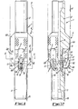
- Fig. 1 is a side view of a tool for enlarging
- well bores in accordance with the invention;
- Fig. 2 is a part-sectional angled side view of
- the tool of Fig. 1; and
- Fig. 3 is a sectional view on the line A-A
- of Fig. 1.
- Referring to the drawings, the tool of this embodiment of the invention has a housing generally indicated at 1 of which top and bottom cylindrical sections 2, 3 of 241 mm outside diameter and a middle cylindrical section 4 is of 444 mm outside diameter at its
upper portion 4A. The housing 1 has an overall length of 2121 mm. - A
lower portion 4B of the middle section is of reduced outside diameter and has threeequispaced slots 5 cut into it, theslots receiving cutters 6 havingcutting edges outermost cutting edges 6C describe a circle having a diameter of 444 mm, i.e. the same as the diameter of theupper portion 4A of the housing middle section. - Each
cutter 6 is secured within itsslot 5 by means of twoscrewed pins 12 passing through thecutter 6 and screwing into theportion 4B of the housing 1 (see Fig. 3) which forces thecutter 6 against a side face of theslot 5, thereby preventing vibration of thecutter 6 in the slot. Each screwed pin is prevented from loosening by means of aneccentric locking disc 12A. - At their lower portion the
cutters 6 are forked at 11, thecutting edges 6 being provided on each fork. - A through bore 8 extends axially through the housing and apertures 9, 10 open from the bore 8 radially outwardly into the
slots 5 between theforks 11 of eachcutter 6. The apertures 9, 10 are disposed at the same level on the housing 1 as thecutting edges - The apertures 10 are directed along the
cutting edges 6A. - Located within the apertures 9, 10 are
removable sleeves 14 which are aligned with the bore 8 by dowel pins 13.Nozzles 15 are disposed within thesleeves 14 and sealed against their inner faces to provide a reducing cross- sectional area for the apertures 9, 10 as they emerge from the bore 8. Thenozzles 15 are removable and interchangeable, and their total area at their outer ends is 0.9 cm2. - In use, the tool of this embodiment of the invention is screwed at its upper and lower ends into a drill string, so that the bore 8 communicates with fluid passageways above and below it. The string carries at its lower end a drill bit (not shown) which forms a pilot hole 16 (Fig. 2) in the sea bed on rotation of the string, or a bullnose which will follow an existing pilot hole.
- Drilling fluid is pumped through the drill string and passes through the bore 8 to the drill bit and, being under pressure, is forced in part through the
nozzles 15, emerging from them at a velocity of 60-100 metres per sec. The pressure drop across thenozzles 15 is around 70 kg per cm2. The rate of fluid flow through the nozzles is 5455 litres per minute. - As the fluid is jetted through the
nozzles 15 it forces debris away from thecutting edges edge 6A. Cuttings are then entrained in the upward flow of fluid from the drill bit, which is joined by the fluid from thenozzles 15. Further, the high velocity of the fluid from thenozzles 15 against the wall of the well bore assists the cutting action of the cutters by causing initial weakening and breakage of the wall; as the fluid flow from the nozzles is lateral of the well bore it acts directly against the bore wall generally in the plane of rock strata, thus producing a disruptive effect on the wall. The localised high pressure created by the fluid from the nozzles also reduces the "chip hold-down" effect of a substantially downwardly-directed jet, thus reducing wear on thecutting edges - Thus the
pilot hole 16 is opened to a wider diameter by thecutters 6, providing a drill hole 17 (Fig. 2) of about 444 mm diameter. As the tool rotates, therefore, theupper portion 4A of the housing's middle section bears against the wall of the drill hole 17, providing stabilisation for the tool. The face of the newly-formed drill hole 17 is smoother and has more integrity than that of thepilot hole 16, and therefore provides better stabilisation for the tool than conventional arrangements in which the stabilisation is effected against the pilot hole. - There are several reasons for the high level of performance achieved by the tool of this embodiment:
- 1) The impact of the high velocity jet was breaking down the ledge.
- 2) The lateral jet was carrying away the cutting effectively as it only had to turn 90° to be travelling up the hole as opposed to 180° as in normal jet nozzle bits or hole openers.
- 3) Creating a wash-out situation relieved the cutters of much of their work.
- 4) Creating localised high formation pressure reduced the chip hold down effect.
- It is a well-known fact that chip hold down is affected greatly by over-balance and if the lateral jetting is causing formation pressure to be increased to a level above the hydrostatic pressure of the mud column, then a substantial increase in rate of penetration will certainly take place.
- This now remains to be proved under laboratory conditions.
- Increases in ROP have been achieved in the past using nozzles to reduce bottom hole pressure but this method of increasing the ROP has been accompanied with the increased risk of causing an influx by reducing or removing the over-balance excited by the mud column. In the case of lateral jetting in the present invention this is not the case as the formation pressure is being increased locally at the point of cutting which would effectively reduce the risk of an influx but still reduce or remove the over-balance exerted by the mud column.
- Modifications and improvements may be made without departing from the scope of the invention.
Claims (8)
Applications Claiming Priority (4)
| Application Number | Priority Date | Filing Date | Title |
|---|---|---|---|
| US634956 | 1984-07-27 | ||
| US06/634,956 US4589504A (en) | 1984-07-27 | 1984-07-27 | Well bore enlarger |
| GB8510911 | 1985-04-30 | ||
| GB858510911A GB8510911D0 (en) | 1985-04-30 | 1985-04-30 | Hole opener |
Publications (2)
| Publication Number | Publication Date |
|---|---|
| EP0176180A1 true EP0176180A1 (en) | 1986-04-02 |
| EP0176180B1 EP0176180B1 (en) | 1988-11-30 |
Family
ID=26289185
Family Applications (1)
| Application Number | Title | Priority Date | Filing Date |
|---|---|---|---|
| EP85305111A Expired EP0176180B1 (en) | 1984-07-27 | 1985-07-18 | Hole opener |
Country Status (3)
| Country | Link |
|---|---|
| EP (1) | EP0176180B1 (en) |
| DE (1) | DE3566564D1 (en) |
| NO (1) | NO169609C (en) |
Cited By (4)
| Publication number | Priority date | Publication date | Assignee | Title |
|---|---|---|---|---|
| EP0257944A2 (en) * | 1986-08-21 | 1988-03-02 | Smith International (North Sea) Limited | Milling tool |
| DE4012222A1 (en) * | 1990-04-14 | 1991-10-17 | Gerhard Bihler | Deep boring drill assembly - has quick tool-changing mechanism to substitute roller chisels and fixed chisels |
| WO1993025794A1 (en) * | 1992-06-05 | 1993-12-23 | Panther Oil Tools (Uk) Limited | Well drilling tools |
| GB2389132A (en) * | 2002-05-28 | 2003-12-03 | Smith International | Fixed blade symmetrical hole opener |
Families Citing this family (1)
| Publication number | Priority date | Publication date | Assignee | Title |
|---|---|---|---|---|
| SE506342C2 (en) * | 1996-04-09 | 1997-12-08 | Sandvik Ab | Clearing tools for rock drilling and ancillary part for this |
Citations (10)
| Publication number | Priority date | Publication date | Assignee | Title |
|---|---|---|---|---|
| US2028910A (en) * | 1934-02-03 | 1936-01-28 | John W Macclatchie | Reamer |
| US2140417A (en) * | 1937-12-28 | 1938-12-13 | Conklin Ancil Brooks | Core taker for rotary drills |
| US2149798A (en) * | 1936-06-27 | 1939-03-07 | Arthur E Krick | Well-drilling bit |
| US2249732A (en) * | 1939-09-22 | 1941-07-22 | Paul F Green | Off center reamer |
| US2607562A (en) * | 1951-03-19 | 1952-08-19 | Phipps Orville | Self-piloted rotary drill bit |
| GB788104A (en) * | 1954-10-01 | 1957-12-23 | Modern Hardmetals Ltd | Improvements in or relating to rock drilling bits |
| US3237705A (en) * | 1963-11-13 | 1966-03-01 | Williams Joseph W | Reamer for enlarging and straightening bore holes |
| US3324957A (en) * | 1963-09-24 | 1967-06-13 | Gulf Research Development Co | Hydraulic jet method of drilling a well through hard formations |
| US3908771A (en) * | 1974-03-01 | 1975-09-30 | Wylie P Garrett | Drill collar incorporating device for jetting drilling fluid transversely into bore hole |
| US4445580A (en) * | 1979-06-19 | 1984-05-01 | Syndrill Carbide Diamond Company | Deep hole rock drill bit |
-
1985
- 1985-07-18 EP EP85305111A patent/EP0176180B1/en not_active Expired
- 1985-07-18 DE DE8585305111T patent/DE3566564D1/en not_active Expired
- 1985-07-26 NO NO852975A patent/NO169609C/en not_active IP Right Cessation
Patent Citations (10)
| Publication number | Priority date | Publication date | Assignee | Title |
|---|---|---|---|---|
| US2028910A (en) * | 1934-02-03 | 1936-01-28 | John W Macclatchie | Reamer |
| US2149798A (en) * | 1936-06-27 | 1939-03-07 | Arthur E Krick | Well-drilling bit |
| US2140417A (en) * | 1937-12-28 | 1938-12-13 | Conklin Ancil Brooks | Core taker for rotary drills |
| US2249732A (en) * | 1939-09-22 | 1941-07-22 | Paul F Green | Off center reamer |
| US2607562A (en) * | 1951-03-19 | 1952-08-19 | Phipps Orville | Self-piloted rotary drill bit |
| GB788104A (en) * | 1954-10-01 | 1957-12-23 | Modern Hardmetals Ltd | Improvements in or relating to rock drilling bits |
| US3324957A (en) * | 1963-09-24 | 1967-06-13 | Gulf Research Development Co | Hydraulic jet method of drilling a well through hard formations |
| US3237705A (en) * | 1963-11-13 | 1966-03-01 | Williams Joseph W | Reamer for enlarging and straightening bore holes |
| US3908771A (en) * | 1974-03-01 | 1975-09-30 | Wylie P Garrett | Drill collar incorporating device for jetting drilling fluid transversely into bore hole |
| US4445580A (en) * | 1979-06-19 | 1984-05-01 | Syndrill Carbide Diamond Company | Deep hole rock drill bit |
Cited By (7)
| Publication number | Priority date | Publication date | Assignee | Title |
|---|---|---|---|---|
| EP0257944A2 (en) * | 1986-08-21 | 1988-03-02 | Smith International (North Sea) Limited | Milling tool |
| EP0257944A3 (en) * | 1986-08-21 | 1989-05-24 | Smith International (North Sea) Limited | Milling tool |
| DE4012222A1 (en) * | 1990-04-14 | 1991-10-17 | Gerhard Bihler | Deep boring drill assembly - has quick tool-changing mechanism to substitute roller chisels and fixed chisels |
| WO1993025794A1 (en) * | 1992-06-05 | 1993-12-23 | Panther Oil Tools (Uk) Limited | Well drilling tools |
| GB2389132A (en) * | 2002-05-28 | 2003-12-03 | Smith International | Fixed blade symmetrical hole opener |
| US6742607B2 (en) | 2002-05-28 | 2004-06-01 | Smith International, Inc. | Fixed blade fixed cutter hole opener |
| GB2389132B (en) * | 2002-05-28 | 2005-04-20 | Smith International | Fixed blade fixed cutter hole opener |
Also Published As
| Publication number | Publication date |
|---|---|
| NO169609B (en) | 1992-04-06 |
| NO169609C (en) | 1992-07-15 |
| DE3566564D1 (en) | 1989-01-05 |
| EP0176180B1 (en) | 1988-11-30 |
| NO852975L (en) | 1986-01-28 |
Similar Documents
| Publication | Publication Date | Title |
|---|---|---|
| US4640374A (en) | Rotary drill bit | |
| US4408671A (en) | Roller cone drill bit | |
| US5775443A (en) | Jet pump drilling apparatus and method | |
| US4618010A (en) | Hole opener | |
| US6338390B1 (en) | Method and apparatus for drilling a subterranean formation employing drill bit oscillation | |
| CA1202955A (en) | Drill bit for jet assisted rotary drilling | |
| US3727704A (en) | Diamond drill bit | |
| US5836404A (en) | Drill bits with enhanced hydraulic flow characteristics | |
| GB2385618A (en) | Device for drilling a subterranean formation with variable depth of cut | |
| CA2008567A1 (en) | Combination drill bit | |
| CA1263109A (en) | Integral blade hole opener | |
| NO810521L (en) | MOUNTAIN DRILL FOR DRILLING DEEP HOLES. | |
| US6926099B2 (en) | Drill out bi-center bit and method for using same | |
| US7886851B2 (en) | Drill bit nozzle | |
| US3433331A (en) | Diamond drill bit | |
| US3199617A (en) | Drilling bit | |
| EP0058061A2 (en) | Tools for underground formations | |
| CN100458097C (en) | Percussive drill bit, drilling system comprising such a drill bit and method of drilling a bore hole | |
| EP0176180A1 (en) | Hole opener | |
| US4911729A (en) | Overburden eliminator rock drill bit | |
| US5740873A (en) | Rotary bit with gageless waist | |
| US3548960A (en) | Drill bit having rotating stand-off elements | |
| US7373994B2 (en) | Self cleaning coring bit | |
| US3283837A (en) | Drill bit | |
| US20100276206A1 (en) | Rotary Drill Bit |
Legal Events
| Date | Code | Title | Description |
|---|---|---|---|
| PUAI | Public reference made under article 153(3) epc to a published international application that has entered the european phase |
Free format text: ORIGINAL CODE: 0009012 |
|
| AK | Designated contracting states |
Kind code of ref document: A1 Designated state(s): DE FR GB NL |
|
| 17P | Request for examination filed |
Effective date: 19860818 |
|
| 17Q | First examination report despatched |
Effective date: 19871006 |
|
| GRAA | (expected) grant |
Free format text: ORIGINAL CODE: 0009210 |
|
| AK | Designated contracting states |
Kind code of ref document: B1 Designated state(s): DE FR GB NL |
|
| REF | Corresponds to: |
Ref document number: 3566564 Country of ref document: DE Date of ref document: 19890105 |
|
| EN | Fr: translation not filed | ||
| PLBE | No opposition filed within time limit |
Free format text: ORIGINAL CODE: 0009261 |
|
| STAA | Information on the status of an ep patent application or granted ep patent |
Free format text: STATUS: NO OPPOSITION FILED WITHIN TIME LIMIT |
|
| 26N | No opposition filed | ||
| PGFP | Annual fee paid to national office [announced via postgrant information from national office to epo] |
Ref country code: FR Payment date: 19910731 Year of fee payment: 7 |
|
| PG25 | Lapsed in a contracting state [announced via postgrant information from national office to epo] |
Ref country code: FR Free format text: LAPSE BECAUSE OF FAILURE TO SUBMIT A TRANSLATION OF THE DESCRIPTION OR TO PAY THE FEE WITHIN THE PRESCRIBED TIME-LIMIT Effective date: 20000731 |
|
| REG | Reference to a national code |
Ref country code: GB Ref legal event code: IF02 |
|
| PGFP | Annual fee paid to national office [announced via postgrant information from national office to epo] |
Ref country code: GB Payment date: 20030612 Year of fee payment: 19 |
|
| PGFP | Annual fee paid to national office [announced via postgrant information from national office to epo] |
Ref country code: NL Payment date: 20030619 Year of fee payment: 19 |
|
| PGFP | Annual fee paid to national office [announced via postgrant information from national office to epo] |
Ref country code: DE Payment date: 20030731 Year of fee payment: 19 |
|
| PG25 | Lapsed in a contracting state [announced via postgrant information from national office to epo] |
Ref country code: GB Free format text: LAPSE BECAUSE OF NON-PAYMENT OF DUE FEES Effective date: 20040718 |
|
| PG25 | Lapsed in a contracting state [announced via postgrant information from national office to epo] |
Ref country code: NL Free format text: LAPSE BECAUSE OF NON-PAYMENT OF DUE FEES Effective date: 20050201 Ref country code: DE Free format text: LAPSE BECAUSE OF NON-PAYMENT OF DUE FEES Effective date: 20050201 |
|
| GBPC | Gb: european patent ceased through non-payment of renewal fee |
Effective date: 20040718 |
|
| NLV4 | Nl: lapsed or anulled due to non-payment of the annual fee |
Effective date: 20050201 |
|
| PG25 | Lapsed in a contracting state [announced via postgrant information from national office to epo] |
Ref country code: FR Free format text: LAPSE BECAUSE OF FAILURE TO SUBMIT A TRANSLATION OF THE DESCRIPTION OR TO PAY THE FEE WITHIN THE PRESCRIBED TIME-LIMIT Effective date: 19920731 |
|
| PG25 | Lapsed in a contracting state [announced via postgrant information from national office to epo] |
Ref country code: FR Free format text: LAPSE BECAUSE OF FAILURE TO SUBMIT A TRANSLATION OF THE DESCRIPTION OR TO PAY THE FEE WITHIN THE PRESCRIBED TIME-LIMIT Effective date: 19910731 |
|
| PG25 | Lapsed in a contracting state [announced via postgrant information from national office to epo] |
Ref country code: FR Free format text: LAPSE BECAUSE OF FAILURE TO SUBMIT A TRANSLATION OF THE DESCRIPTION OR TO PAY THE FEE WITHIN THE PRESCRIBED TIME-LIMIT Effective date: 19890731 |